WO2012119314A1 - 干扰协调方法、基站和用户设备 - Google Patents
干扰协调方法、基站和用户设备 Download PDFInfo
- Publication number
- WO2012119314A1 WO2012119314A1 PCT/CN2011/071677 CN2011071677W WO2012119314A1 WO 2012119314 A1 WO2012119314 A1 WO 2012119314A1 CN 2011071677 W CN2011071677 W CN 2011071677W WO 2012119314 A1 WO2012119314 A1 WO 2012119314A1
- Authority
- WO
- WIPO (PCT)
- Prior art keywords
- signal
- user equipment
- macro cell
- base station
- macro
- Prior art date
- Legal status (The legal status is an assumption and is not a legal conclusion. Google has not performed a legal analysis and makes no representation as to the accuracy of the status listed.)
- Ceased
Links
Classifications
-
- H—ELECTRICITY
- H04—ELECTRIC COMMUNICATION TECHNIQUE
- H04L—TRANSMISSION OF DIGITAL INFORMATION, e.g. TELEGRAPHIC COMMUNICATION
- H04L5/00—Arrangements affording multiple use of the transmission path
- H04L5/003—Arrangements for allocating sub-channels of the transmission path
- H04L5/0032—Distributed allocation, i.e. involving a plurality of allocating devices, each making partial allocation
-
- H—ELECTRICITY
- H04—ELECTRIC COMMUNICATION TECHNIQUE
- H04W—WIRELESS COMMUNICATION NETWORKS
- H04W16/00—Network planning, e.g. coverage or traffic planning tools; Network deployment, e.g. resource partitioning or cells structures
- H04W16/24—Cell structures
- H04W16/32—Hierarchical cell structures
-
- H—ELECTRICITY
- H04—ELECTRIC COMMUNICATION TECHNIQUE
- H04B—TRANSMISSION
- H04B7/00—Radio transmission systems, i.e. using radiation field
- H04B7/02—Diversity systems; Multi-antenna system, i.e. transmission or reception using multiple antennas
- H04B7/04—Diversity systems; Multi-antenna system, i.e. transmission or reception using multiple antennas using two or more spaced independent antennas
- H04B7/0413—MIMO systems
- H04B7/0456—Selection of precoding matrices or codebooks, e.g. using matrices antenna weighting
-
- H—ELECTRICITY
- H04—ELECTRIC COMMUNICATION TECHNIQUE
- H04B—TRANSMISSION
- H04B7/00—Radio transmission systems, i.e. using radiation field
- H04B7/02—Diversity systems; Multi-antenna system, i.e. transmission or reception using multiple antennas
- H04B7/04—Diversity systems; Multi-antenna system, i.e. transmission or reception using multiple antennas using two or more spaced independent antennas
- H04B7/06—Diversity systems; Multi-antenna system, i.e. transmission or reception using multiple antennas using two or more spaced independent antennas at the transmitting station
- H04B7/0613—Diversity systems; Multi-antenna system, i.e. transmission or reception using multiple antennas using two or more spaced independent antennas at the transmitting station using simultaneous transmission
- H04B7/0615—Diversity systems; Multi-antenna system, i.e. transmission or reception using multiple antennas using two or more spaced independent antennas at the transmitting station using simultaneous transmission of weighted versions of same signal
- H04B7/0617—Diversity systems; Multi-antenna system, i.e. transmission or reception using multiple antennas using two or more spaced independent antennas at the transmitting station using simultaneous transmission of weighted versions of same signal for beam forming
-
- H—ELECTRICITY
- H04—ELECTRIC COMMUNICATION TECHNIQUE
- H04J—MULTIPLEX COMMUNICATION
- H04J11/00—Orthogonal multiplex systems, e.g. using WALSH codes
- H04J11/0023—Interference mitigation or co-ordination
- H04J11/0026—Interference mitigation or co-ordination of multi-user interference
- H04J11/003—Interference mitigation or co-ordination of multi-user interference at the transmitter
- H04J11/0033—Interference mitigation or co-ordination of multi-user interference at the transmitter by pre-cancellation of known interference, e.g. using a matched filter, dirty paper coder or Thomlinson-Harashima precoder
-
- H—ELECTRICITY
- H04—ELECTRIC COMMUNICATION TECHNIQUE
- H04J—MULTIPLEX COMMUNICATION
- H04J11/00—Orthogonal multiplex systems, e.g. using WALSH codes
- H04J11/0023—Interference mitigation or co-ordination
- H04J11/005—Interference mitigation or co-ordination of intercell interference
- H04J11/0056—Inter-base station aspects
-
- H—ELECTRICITY
- H04—ELECTRIC COMMUNICATION TECHNIQUE
- H04L—TRANSMISSION OF DIGITAL INFORMATION, e.g. TELEGRAPHIC COMMUNICATION
- H04L25/00—Baseband systems
- H04L25/02—Details ; arrangements for supplying electrical power along data transmission lines
- H04L25/03—Shaping networks in transmitter or receiver, e.g. adaptive shaping networks
- H04L25/03891—Spatial equalizers
- H04L25/03898—Spatial equalizers codebook-based design
- H04L25/03904—Spatial equalizers codebook-based design cooperative design, e.g. exchanging of codebook information between base stations
-
- H—ELECTRICITY
- H04—ELECTRIC COMMUNICATION TECHNIQUE
- H04W—WIRELESS COMMUNICATION NETWORKS
- H04W24/00—Supervisory, monitoring or testing arrangements
- H04W24/02—Arrangements for optimising operational condition
-
- H—ELECTRICITY
- H04—ELECTRIC COMMUNICATION TECHNIQUE
- H04W—WIRELESS COMMUNICATION NETWORKS
- H04W52/00—Power management, e.g. Transmission Power Control [TPC] or power classes
- H04W52/02—Power saving arrangements
- H04W52/0209—Power saving arrangements in terminal devices
- H04W52/0212—Power saving arrangements in terminal devices managed by the network, e.g. network or access point is leader and terminal is follower
- H04W52/0216—Power saving arrangements in terminal devices managed by the network, e.g. network or access point is leader and terminal is follower using a pre-established activity schedule, e.g. traffic indication frame
-
- H—ELECTRICITY
- H04—ELECTRIC COMMUNICATION TECHNIQUE
- H04B—TRANSMISSION
- H04B7/00—Radio transmission systems, i.e. using radiation field
- H04B7/02—Diversity systems; Multi-antenna system, i.e. transmission or reception using multiple antennas
- H04B7/04—Diversity systems; Multi-antenna system, i.e. transmission or reception using multiple antennas using two or more spaced independent antennas
- H04B7/0413—MIMO systems
-
- Y—GENERAL TAGGING OF NEW TECHNOLOGICAL DEVELOPMENTS; GENERAL TAGGING OF CROSS-SECTIONAL TECHNOLOGIES SPANNING OVER SEVERAL SECTIONS OF THE IPC; TECHNICAL SUBJECTS COVERED BY FORMER USPC CROSS-REFERENCE ART COLLECTIONS [XRACs] AND DIGESTS
- Y02—TECHNOLOGIES OR APPLICATIONS FOR MITIGATION OR ADAPTATION AGAINST CLIMATE CHANGE
- Y02D—CLIMATE CHANGE MITIGATION TECHNOLOGIES IN INFORMATION AND COMMUNICATION TECHNOLOGIES [ICT], I.E. INFORMATION AND COMMUNICATION TECHNOLOGIES AIMING AT THE REDUCTION OF THEIR OWN ENERGY USE
- Y02D30/00—Reducing energy consumption in communication networks
- Y02D30/70—Reducing energy consumption in communication networks in wireless communication networks
Definitions
- the present invention relates to the field of wireless communications, and in particular, to an interference coordination method, a base station, and a user equipment. Background technique
- LTE-A Long-term Evolution-Advanced
- Figure 1 is a schematic diagram of a typical heterogeneous network system. As shown in Figure 1, in a heterogeneous network of a typical Macro cell + Pico cell, a user equipment that accepts the micro-area B service at the edge of the micro-area B
- the downlink signal interference from the macro cell A indicates that the line is disturbed.
- the downlink control channel PDCCH is transmitted in the form of a broadcast, so that the micro cell Pico cell is interfered by the physical downlink control channel PDCCH of the macro cell Macro cell, and therefore, the heterogeneity is solved.
- Downlink interference in the network an almost blank subframe (ABS: Almost Blank Subframe) scheme is adopted in the LTE-A heterogeneous network. Certain subframes are selected as the ABS in the macro cell, and no control signaling for scheduling data transmission by any user equipment UE is sent in the ABS subframe, and data corresponding to any user equipment UE is not sent.
- the Pico cell may send control signaling and corresponding data for scheduling user equipment UE data in the Pico cell, thereby suppressing interference from the macro cell.
- An object of the embodiments of the present invention is to provide an interference coordination method, a base station, and a user equipment, by which the physical downlink control channel PDCCH of the macro cell Macro cell is substantially eliminated from the micro cell Pico cell, and the performance of the macro cell is not It will have an impact and solve the problems in the prior art.
- An aspect of the present invention provides an interference coordination method, where the method includes: a macro base station precoding a signal of a downlink control channel of a scheduled macro cell user equipment by using a precoding matrix obtained in advance, so as to pass The nulling space of the precoded signal is aligned to the microcell, and/or the strong power direction or feature value of the signal is spatially aligned to the macrocell user equipment.
- Another aspect of an embodiment of the present invention provides an interference coordination method, the method comprising:
- the macro cell user equipment detects a signal of the downlink control channel, and the signal of the downlink control channel is precoded by the macro base station, so that the nulling space of the signal formed by the precoding is aligned with the micro cell, and/or the strong power of the signal is
- the direction or feature value is spatially aligned to the macro cell user equipment; the macro cell user equipment decodes the signal according to a channel estimation result or according to a previously obtained related information including a precoding matrix.
- a macro base station includes: a first signal processing unit, configured to use, by using a precoding matrix obtained in advance, a downlink control channel of the scheduled macro cell user equipment. The signal is precoded;
- An antenna unit for transmitting a precoded signal, aligning the nulling space of the signal formed by the precoding with the microcell, and/or spatially aligning the strong power direction or characteristic value of the signal with the macrocell user equipment.
- a user equipment is provided, where the user equipment includes:
- a signal detecting unit configured to detect a signal of a downlink control channel, where the downlink control channel The signal is precoded by the macro base station to align the null space of the signal formed by the precoding to the micro cell, and/or to spatially align the strong power direction/feature value of the signal to the macro cell user equipment; And a unit, configured to decode the signal detected by the signal detecting unit according to the channel estimation result or according to the related information including the precoding matrix obtained in advance.
- a computer readable program wherein when the program is executed in a macro base station, the program causes a computer to execute the interference coordination method in the macro base station.
- a storage medium storing a computer readable program, wherein the computer readable program causes a computer to execute the interference coordination method described above in a macro base station.
- a computer readable program wherein when the program is executed in a user device, the program causes a computer to execute the interference coordination method in the user equipment.
- a storage medium storing a computer readable program, wherein the computer readable program causes a computer to execute the interference coordination method described above in a user equipment.
- the beneficial effects of the embodiment of the present invention are as follows: precoding the signal of the downlink control channel, so that the null space (nul l space ) formed by the precoding is aligned with the micro cell, thereby substantially eliminating the macro cell of the macro cell.
- the physical downlink control channel PDCCH interferes with the micro cell Pico cell and does not affect the performance of the macro cell, and solves the problems in the prior art; in addition, by aligning the strong power direction/feature value of the signal
- the macro cell user equipment can further improve the receiving performance of the macro cell user equipment, and further reduce the interference of the macro base station micro area.
- Figure 1 is a schematic diagram of a typical heterogeneous network system
- FIG. 2 is a flowchart of a method for configuring related information on a macro base station side in Embodiment 1 of the present invention
- FIG. 3 is a flowchart of an interference coordination method according to Embodiment 2 of the present invention
- FIG. 5 is a flowchart of a method for an interference system according to Embodiment 4 of the present invention.
- FIG. 6 is a schematic diagram showing the structure of a macro base station according to Embodiment 5 of the present invention.
- Figure 7 is a block diagram showing the structure of a macro base station according to Embodiment 6 of the present invention.
- FIG. 8 is a block diagram showing the structure of a user equipment according to Embodiment 7 of the present invention. detailed description
- the embodiments of the present invention are coordinated by interference in a heterogeneous network system of LTE-A (Long Term Evaluation Advanced).
- LTE-A Long Term Evaluation Advanced
- the description will be made, but it will be understood that the present invention is not limited to the above system and is applicable to other systems involving interference coordination between cells.
- An embodiment of the present invention provides an interference coordination method, where the method includes: a macro base station precoding a signal of a downlink control channel of a scheduled macro cell user equipment by using a precoding matrix obtained in advance, so that a signal formed by precoding is zero.
- the null space is aligned with the microcell, and/or the strong power direction/feature value of the signal is spatially aligned to the macrocell user equipment.
- the signal of the PDCCH may be pre-coded, and the null space (nul l space ) formed by precoding may be aligned with the micro cell, or the strong power direction of the signal, such as a feature value space pair. Quasi-macro cell user equipment;
- the signal of the PDCCH may be pre-coded such that the signal null space (nul l space) formed by pre-coding is aligned with the micro cell, and the signal feature value is spatially aligned with the macro cell user equipment. Different interference coordination methods can be adopted according to actual conditions.
- the downlink control channel PDCCH is transmitted in the form of a broadcast, so that the Pico cell is interfered by the physical downlink control channel PDCCH of the macro cell, and therefore, in order to eliminate the downlink interference, the present invention
- the signal of the downlink control channel PDCCH is pre-coded, so that the null space formed by the precoding is aligned with the micro cell, thereby substantially eliminating the physical downlink control of the macro cell.
- the channel PDCCH interferes with the micro cell Pico cell and does not affect the performance of the macro cell, which solves the problems in the prior art.
- the receiving performance of the macro cell user equipment can be further improved, and the interference of the macro base station to the micro area is further reduced.
- the macro base station may multiply the signal of the downlink control channel by the precoding matrix. Aligning the signal nullization space formed by precoding with the microcell, and/or spatially aligning the strong power direction/feature value of the signal with the macro cell user equipment.
- the signal of the PDCCH may be processed by using any precoding processing manner similar to the prior art, and finally, the zero space of the signal is aligned with the micro area, and/or the feature value space of the signal is made. Quasi-macro cell user equipment.
- the precoding matrix may also be generated in such a manner that the macro base station generates the precoding matrix according to the channel information of the micro cell or according to the channel information of the micro cell and the channel information of the macro cell user equipment.
- the precoding matrix can be generated by using location information or phase information included in the channel information. Different generation methods can be used for different antenna deployments. The following examples are given.
- the macro base station is based on channel information of a micro cell (Pico cel l ) to a macro base station (Macro cel eNB), or based on channel information of a micro cell to a macro base station, and based on a macro cell user equipment (Macro cel l UE )
- the channel information of the macro base station generates a precoding matrix for precoding the PDCCH of the macro cell (Macro cel 1 ) on the macro base station side.
- the required channel information may be based on the location information of the micro cell relative to the macro base station, or The direction location information of the macro cell user equipment relative to the macro base station; may also be obtained based on the channel information measured and fed back to the macro base station by the macro cell user equipment.
- the macro base station may obtain the amplitude and phase of each array element according to the location of the micro cell or according to the location of the micro cell and the location of the macro cell user equipment, and generate beamforming according to certain criteria.
- the array factor i.e., equivalent to the precoding matrix
- the array factor is such that the 'zero point' (or 'zero limit') containing zero radiated power is aligned to the microcell while the lobe of the maximum radiated power direction is aligned with the macrocell user equipment.
- it is also a method of precoding, which forms a zero point, that is, a zeroing interval is aligned with the micro cell.
- the microcell is aligned in the null space of the beam formed by the antenna, and the interference of the physical downlink control channel PDCCH of the macro cell to the pico cell of the micro cell is eliminated, and the precoding is performed by the foregoing.
- the processing is performed to align the direction of the strong power lobes with the macro cell user equipment, so that not only the interference of the macro cell to the micro cell but also the receiving performance of the macro cell user equipment can be improved.
- the antenna array can simultaneously generate multiple 'zero points'.
- a 'zero point' can be formed in M-2 directions, thereby avoiding interference to M-2 micro-cells at the same time, where M is Natural number.
- M is Natural number.
- Example 3 For a less relevant antenna configuration, such as a polarized antenna, the channel information of the macro cell user to the macro base station and the relative position information of the macro cell and the micro interval fed back by the macro cell user equipment may be selected to select a corresponding precoding.
- a matrix such that the precoding matrix and the channel of the macro base station to the micro cell user equipment (Pico cel l UE) are orthogonal to each other, and simultaneously communicate with the macro base station (Macro cel l eNB ) to the macro cell user equipment (Macro cel l UE ) Match.
- the foregoing method for generating the precoding matrix is only an embodiment. In addition to the foregoing manner, other manners may be used, which are not described here.
- the PDCCH is precoded by using the precoding matrix.
- the signal nulling interval formed by the precoding is aligned with the micro cell, thereby eliminating the interference of the macro cell to the micro cell, and the method does not affect the performance of the macro cell.
- the strong power direction of the signal can be aligned with the macro cell user equipment, which not only eliminates the interference of the macro cell to the micro cell, but also improves the receiving performance of the macro cell user equipment.
- the macro base station may store matrix element information of the precoding matrix, where the user equipment may generate information by using the matrix element information.
- the corresponding matrix may include the value of each element in the matrix, or may only include a certain information, for example, for the antenna array, only the phase information ⁇ is included, so that all element values f ( e ) in the matrix can be derived.
- the matrix elements of the precoding matrix may be stored corresponding to the matrix index, so that the matrix elements of the precoding matrix can be found by the matrix index, thereby obtaining the precoding matrix.
- the method may further include: configuring whether to indicate that the macro cell user equipment is pre-coded such that the signal nullification space formed by precoding is aligned with the micro cell, and/or the strong power direction or characteristic value of the signal is made.
- the space is aligned with the subframe information of the macro cell user equipment, and the above information may also be stored.
- bit value For example, for subframes 1-10, the number of bits of each subframe can be matched.
- the generated pre- The coding matrix pre-codes the signal of the downlink control channel, so that the signal nullization space formed by the pre-coding is aligned with the micro-region, and/or the strong power direction or the feature value of the signal is spatially aligned with the macro-cell user equipment;
- the bit value corresponding to the subframe is "0" it means that the signal of the downlink control channel is not precoded by using the generated precoding matrix, and other multi-antenna processing methods configured by the system, such as the transmit diversity method, are used for precoding.
- Table 1 it is a mapping table (subframe information) of a subframe and a bit value.
- the method may further include: determining, according to the subframe information, the current Whether the subframe is pre-coded for the signal of the downlink control channel, the signal nullization space formed by the pre-coding is aligned with the micro-region, and/or the strong power direction or the feature value of the signal is spatially aligned with the sub-cell user equipment. frame;
- the macro base station determines to precode the signal of the downlink control channel of the scheduled macro cell user equipment, so that the signal nullification space formed by precoding is aligned with the micro area, and/or the signal is made.
- the strong power direction or feature value space is aligned with the macro cell user equipment.
- the macro base station may generate a precoding matrix according to an actual situation, and generate a pre- When the matrix is encoded, the precoding matrix of at least one macro cell user equipment may be different from the precoding matrix of other macro cell user equipments.
- the precoding matrices of the user equipments 1 and 5 generated by the macro base station are the same, and the precoding matrices corresponding to the other user equipments are different, wherein the precoding matrix is represented by a matrix index, on the base station side or the user equipment side.
- the matrix element information of the precoding matrix corresponding to the matrix index is stored.
- Precoding matrix for the same macro cell user equipment, in different situations, for example, different precoding matrices corresponding to different subframes or different subframes, different subframes corresponding to different users are used differently. Precoding matrix.
- the precoding matrix corresponding to at least one subframe is different from the precoding matrix corresponding to other subframes, as shown in Table 3.
- Table 3 As shown in Table 3, for the subframes of subframe numbers 5 and 10, the matrix index of the corresponding precoding matrix is 5, and the index of the precoding matrix corresponding to the remaining subframes is 1.
- different information is configured for different user equipments, for example, because the location of each user equipment is different, the related information corresponding to at least one macro cell user equipment and related information of other user equipments, that is, subframes.
- Information and precoding matrix are different, as shown in Table 4-Guang 4-3.
- Table 4-3 User equipment 3 As shown in Table 4-1, for user equipment 1, the subframe number is 10, and the precoding matrix index number is 5, which means that the signal of the PDCCH is precoded when the subframe number is 10, and the index number of the matrix used is used. 5; as shown in Table 4-2, for user equipment 2, the subframe number is 5, the precoding matrix index number is 2, as shown in Table 4-3, and for user equipment 3, the subframe number is 10, the precoding matrix. The index number is 8.
- the macro base station may further configure information related to the PDCCH transmission power, such as the power value of each step and the power adjustment step size information, for example, assuming that each step corresponds to a power value of 2 dB,
- the power modulation step size information that is, the step index '3' indicates 6 dB, and this parameter can also be the value of the power adjustment.
- the macro base station may configure information according to requirements, where only part or all of the foregoing information, such as subframe information, information related to PDCCH transmission power, may be included, and other information may be included as needed. Guarantee the reception performance of the PDCCH.
- the macro base station may further determine whether to send the generated precoding matrix or the related information such as the precoding matrix and the configured subframe information to the macro cell user equipment.
- the macro base station does not need to notify the macro cell user equipment that the precoding matrix, the subframe information, and the PDCCH transmit power are related information. . And this information is only used on the macro base station side. In this case, regardless of whether the macro base station precodes the signal of the PDCCH, the macro cell user equipment performs blind detection on the PDCCH, that is, performs multi-antenna decoding according to the channel estimation result.
- DM-RS Demodulation Reference Signal
- the macro base station can also notify the macro cell user equipment of the above related information.
- the macro base station precodes the signal of the PDCCH
- the nulling space of the beam formed by the antenna is aligned with the micro cell, and/or the direction of the lobe is aligned with the macro cell user equipment, in the macro cell.
- the PDCCH signal may be decoded according to the obtained related information.
- the macro base station may separately notify the user equipment of the generated precoding matrix, or the configured subframe information, and the related information, and may also pass the related information.
- the high-level signaling such as the radio resource control (RRC) signaling, notifies the macro cell user equipment, so that when the macro cell user equipment detects the signal of the PDCCH, the PDCCH signal can be correctly decoded according to the obtained related information.
- RRC radio resource control
- the following is an example in which the macro base station dynamically configures related information through high layer signaling and notifies the user equipment as an example.
- Fig. 2 is a flow chart showing the configuration information of the macro base station side in the first embodiment of the present invention. As shown in Figure 2, the following steps are included:
- Step 201 The macro base station generates a precoding matrix according to channel information of the micro cell or according to channel information of the micro cell and channel information of the macro cell user equipment.
- the manner of generating the precoding matrix may be any one of the existing methods, and the foregoing manners of the embodiments of the present invention may be used, and details are not described herein; wherein, the location information included in the channel information may be used or Phase information is generated.
- Step 202 The macro base station generates a high layer that includes at least the related information of the foregoing precoding matrix, where the high layer signaling may be RRC signaling;
- the related information may further include a PDCCH transmit power in addition to the foregoing information.
- the related information may further include using subframe information, where the subframe information may indicate which subframe is in the subframe.
- the signal of the PDCCH is precoded, that is, the subframe information used to indicate whether the macro cell user equipment is precoded;
- the related information is as shown in Table 5. It should be noted that the macro base station may include only some or all of the related information according to requirements, and may also include other information as needed to ensure the receiving performance of the PDCCH.
- Step 203 The macro base station sends the high layer signaling to the corresponding macro cell user equipment, so that The user equipment obtains related information included in the high layer signaling;
- the macro base station may send the high layer signaling to the macro cell user equipment by using the PDSCH, but the method is not limited to this manner, and the high layer signaling may be transmitted in other manners.
- the above step 203 can also be omitted.
- the macro base station may use different indication manners to indicate the related information, which is exemplified below with reference to Table 5:
- the "precoding matrix matrix” may be used to indicate the "precoding matrix matrix” by means of a matrix index. If such an indication mode is adopted, the macro needs to store the same matrix on both the base station side and the macro cell user equipment side. a one-to-one correspondence between the element and the matrix index, and the macro base station notifies the macro cell user equipment of the matrix index;
- the "precoding matrix matrix” may also be matrix element information, and the matrix element information is notified to the corresponding macro cell user equipment, so that the user equipment can generate a corresponding matrix by using the matrix element information;
- the matrix element information may include the value of each element in the matrix, or may only include a certain information.
- the phase information ⁇ may be included, so that all element values f ( e ) in the matrix may be derived. .
- the "PDCCH transmit power" may be power adjustment step information. For example, if the power corresponding to each step is 2 dB, the step index '3' indicates 6 dB; or it may be the value of the power adjustment.
- the subframe may be indicated by using a mapping manner of a subframe and a bit value. For example, as shown in Table 1, a total of 10 bits are used to represent 10 subframes, such as Subframe wide subframe 10. If the bit value is 1, it indicates that the corresponding subframe decodes the signal of the PDCCH according to the "precoding matrix", in this embodiment, the subframe with the subframe number is 10; and the bit value is 0, indicating the corresponding subframe.
- the processing of the signal of the PDCCH is not based on the high layer signaling, but is based on the transmission mode PDCCH of the cell uniform configuration. Taking the LTE system as an example, the PDCCHs of these subframes are not precoded, but transmit diversity.
- the macro base station can configure related information required for precoding by the macro base station by using high layer signaling, such as RRC signaling, and the related information may include a precoding matrix matrix, which may be The actual situation determines whether the related information is notified to the macro cell user equipment through high layer signaling.
- the macro base station can use the related information to adjust The signal of the downlink control channel (PDCCH) of the macro cell user equipment is precoded, and in the case that the macro cell user equipment needs to use the related information, the related information may also be used to correctly correct the signal of the PDCCH subjected to precoding processing. Decoding.
- PDCCH downlink control channel
- Embodiment 2 of the present invention will be described below with reference to the drawings.
- the process of precoding the signal of the PDCCH by using the related information configured by the macro base station by using the high layer signaling as an example is described in detail.
- FIG. 3 is a flow chart of an interference coordination method according to Embodiment 2 of the present invention. As shown in Figure 3, the method includes:
- Step 301 The macro base station generates a precoding matrix according to channel information of the micro cell or according to channel information of the micro cell and channel information of the macro cell user equipment.
- the macro base station generates the related information based on the location information of the micro cell and the location information of the macro cell user equipment, and the channel information may include the location information or the phase information, and the method for generating is as described in Embodiment 1, and details are not described herein. .
- Step 302 The macro base station generates high-level signaling of the related information including at least the foregoing precoding matrix, so that the macro cell user equipment can correctly decode the detected PDCCH according to the related information.
- the related information includes, in addition to the foregoing information, subframe information, where the subframe information indicates, in which subframe, the signal of the PDCCH is pre-coded, that is, a subframe for indicating whether to pre-encode the macro cell user equipment.
- subframe information indicates, in which subframe, the signal of the PDCCH is pre-coded, that is, a subframe for indicating whether to pre-encode the macro cell user equipment.
- the corresponding matrices may be the same or different, and the corresponding subframe information may be the same or different;
- the macro base station may further include other information as needed to ensure the receiving performance of the PDCCH according to requirements.
- Step 303 The macro base station notifies the corresponding macro cell user equipment of the high layer signaling, so that the user equipment obtains related information included in the high layer signaling.
- the information of the notification is as shown in Table 3, wherein the matrix is indicated by a matrix index, so that the microcell needs to notify the user equipment of the correspondence between the matrix element and the matrix index, and the macro base station and the macro cell user equipment. Side storage.
- the macro base station can input the signal of the PDCCH according to the foregoing information configured by the high layer signaling. Multi-antenna processing.
- Step 304 When the macro base station schedules multiple user equipments of the macro cell, the macro base station generates a signal of the downlink control channel of the scheduled macro cell user equipment.
- the process of generating is similar to the prior art, wherein the macro base station may generate corresponding downlink control information DCI according to a transmission mode of each user; perform modulation coding and multiplexing scrambling on the DCI.
- Step 305 The macro base station determines, according to the high layer signaling configured in step 30 above, whether to precode the signal of the downlink control channel of the scheduled macro cell user equipment, so that the signal nullification space pair formed by precoding The quasi-micro cell, and/or the spatial direction or the feature value of the signal is spatially aligned with the macro cell user equipment; if the determination result is yes, step 306 is performed, otherwise step 307 is performed;
- the macro base station may perform the determining according to the configured subframe information of the table 3, and specifically, if: determining, according to the subframe information, that the current subframe is a subframe for precoding the signal of the PDCCH, the macro base station determines to use the generated
- the precoding matrix pre-codes the signal of the downlink control channel of the scheduled macro cell user equipment, so that the signal nullization space formed by precoding is aligned with the micro cell, and/or the strong power direction or feature value space of the signal is made. Align the macro cell user equipment; otherwise, the precoding is not performed, and the signal of the PDCCH is transmitted and diversity by using the multi-antenna method configured by the system;
- the current subframe number is the fifth subframe, it may be determined that the signal of the PDCCH is not processed by using the configured high layer signaling, and step 307 is performed; If the current subframe number is 10, the configured high-level information is used to process the signal of the PDCCH, and then step 306 is performed;
- Step 306 when the determination result in step 305 is YES, the macro base station may perform precoding processing on the signal of the PDCCH according to the generated precoding matrix, so that the signal nullification space formed by precoding is aligned with the micro cell, and/or Aligning a strong power direction or a feature value of the signal with the macro cell user equipment;
- the nulling space of the beam formed by the antenna is aligned with the micro cell, and/or the direction of the lobe is aligned with the macro cell user equipment;
- the matrix is represented by a matrix index, such as a matrix index 5, so that the macro base station can find a corresponding matrix according to the matrix index number 5, and the PDCCH of the user equipment 1
- the signal is processed such that the signal nullification space formed by the precoding is aligned with the microcell, and/or the strong power direction or feature value of the signal is spatially aligned with the macrocell user equipment.
- Step 307 in step 305, if the determination result is no, the signal of the PDCCH is transmitted and diversity according to the multi-antenna mode configured by the system;
- the macro base station performs transmission diversity on the PDCCH signal of the user equipment 1 according to the multi-antenna mode configured by the system.
- the determining step 305 is performed. If the information configured by the macro base station through the high layer signaling is otherwise, if the precoding processing is performed for all the user equipments, the step 305 and the step 307 may be omitted. It is an embodiment of the present invention.
- the macro cell eNB can configure related information required for precoding by the macro base station by using high layer signaling, such as RRC signaling, and notify the macro cell user equipment of the related information.
- the macro base station can use the related information to precode the downlink control channel (PDCCH) signal of the scheduled macro cell user equipment, so that the signal nullification space formed by precoding is aligned with the micro cell, and/or Aligning the strong power direction or the eigenvalue of the signal with the macro cell user equipment, thereby eliminating the interference of the PDCCH signal of the macro base station to the micro cell, avoiding the degradation of the performance of the base station, and solving the problems in the prior art; or Not only improving the receiving performance of the macro cell user equipment, but also further eliminating the interference of the macro cell to the micro cell.
- PDCCH downlink control channel
- An embodiment of the present invention provides an interference coordination method.
- the method includes: Step 401: A macro cell user equipment detects a downlink control channel signal, where a signal of the downlink control channel is precoded by a macro base station to enable The pre-coding formed signal nulling space is aligned with the micro cell, and/or the strong power direction or the feature value of the signal is spatially aligned with the macro cell user equipment; wherein the macro cell user equipment blindly detects the signal of the PDCCH in each subframe;
- Step 402 The macro cell user equipment decodes the signal according to a channel estimation result or according to related information including a precoding matrix obtained in advance.
- the related information may include other information in addition to the precoding matrix, as described in Embodiments 1 and 2, and details are not described herein again.
- the user equipment is not required to learn the related information in some cases, and the corresponding information is used to perform corresponding decoding, as described in Embodiment 1, and details are not described herein.
- the macro cell user equipment can perform multi-antenna decoding based on the channel estimation result in step 402.
- the macro cell user equipment can decode the signal of the PDCCH according to the related information.
- step 402 the following steps may also be included:
- the macro cell user equipment can perform corresponding descrambling, demodulation, channel decoding, and CRC check on the decoded signal, and finally obtain corresponding information; wherein, any existing manner can be used for processing I won't go into details here.
- the macro cell user equipment can correctly process the detected PDCCH signal according to the related information configured by the macro base station.
- the method may further include: receiving related information notified by the macro base station, and further storing the related information.
- the content of the related information is as described in Embodiment 2, and details are not described herein again.
- the method may further include: determining whether to decode the signal of the downlink control channel according to the matrix configured by the macro base station; As shown in Table 1, if the macro cell user equipment determines that the current subframe is a subframe corresponding to the precoding process performed by the macro base station using the matrix configured by the high layer signaling, the user equipment may determine the PDCCH according to the matrix configured by the macro base station. The signal is decoded; otherwise, the signal of the PDCCH is multi-antenna decoded according to the multi-antenna mode configured by the system.
- An embodiment of the present invention provides an interference coordination method.
- the method includes: Step 501: A macro cell user equipment receives related information notified by a macro base station, and further stores the related information.
- the configuration process of the related information is as described in Embodiment 1 and FIG. 2, and details are not described herein. For example, information as shown in Table 1 to Table 5 can be configured.
- Step 502 The macro cell user equipment blindly detects the signal of the PDCCH in each subframe.
- Step 503 Determine whether the current subframe is a subframe corresponding to the precoding process performed by the macro base station by using the precoding matrix configured by the high layer signaling; If yes, go to step 504; otherwise, go to step 507;
- Step 504 The macro cell user equipment decodes the signal according to a precoding matrix matrix in the related information notified by the macro base station.
- Step 505 Perform descrambling and channel decoding on the decoded signal.
- Step 506 Perform a CRC check on the channel decoded signal, and finally obtain the downlink control information.
- Step 507 If the result of the determination is no in step 503, the macro base station performs multi-antenna decoding on the signal of the PDCCH according to the multi-antenna configuration configured by the system;
- steps 508 to 509 are performed to perform descrambling and channel decoding on the decoded signal, and perform CRC check on the channel decoded signal to finally obtain downlink control information.
- processing of the steps 508 to 509 is similar to the processing of the steps 505 to 506, and may be performed by any existing method, and details are not described herein again.
- the macro cell eNB can configure related information required for precoding by the macro base station by using high layer signaling, such as RRC signaling, and notify the macro cell user equipment of the related information.
- the macro base station can use the related information to precode the downlink control channel (PDCCH) signal of the scheduled macro cell user equipment, so that the signal nullification space formed by precoding is aligned with the micro cell, and/or The strong power direction or the eigenvalue of the signal is spatially aligned with the macro cell user equipment, so that the macro cell user equipment can correctly process the detected PDCCH signal according to the related information configured by the macro base station.
- PDCCH downlink control channel
- the embodiment of the present invention further provides a macro base station and a user equipment, as in the following embodiment 4.
- the principle of solving the problem between the macro base station and the user equipment is similar to the interference coordination method based on the macro base station and the user equipment in the foregoing embodiment 1-3. Therefore, the implementation of the macro base station and the user equipment can refer to the implementation of the method, and the repetition is not Let me repeat.
- An embodiment of the present invention provides a macro base station. As shown in FIG. 6, the base station includes a first signal. Processing unit 601 and antenna unit 602; wherein
- the first signal processing unit 601 is configured to precode the signal of the downlink control channel of the scheduled macro cell user equipment by using a precoding matrix obtained in advance;
- the antenna unit 602 is configured to transmit the pre-coded signal, align the signal nullization space formed by the pre-coding with the micro-region, and/or align the strong power mode/feature value of the signal to the macro-cell user equipment.
- the antenna unit 602 can be an adaptive antenna array with strong correlation, or a polarized antenna with weak correlation.
- the macro base station can pre-code the downlink control channel (PDCCH) signal of the scheduled macro cell user equipment by using the obtained precoding matrix, so that the signal formed by precoding is spatially aligned.
- the micro cell, and/or the direction of the strong power direction/eigenvalue space of the signal is aligned with the macro cell user equipment to eliminate the interference of the macro cell to the micro cell, and the performance of the macro cell is not affected; Receive performance of the device.
- PDCCH downlink control channel
- the macro base station may further include a control information generating unit (not shown), where the control information generating unit is configured to generate a signal of the downlink control channel of the scheduled macro cell user equipment, where the process and the embodiment of generating the PDCCH signal Step 304 is similar in 2, and will not be described here.
- the first signal processing unit 601 can perform precoding processing on the signal of the PDCCH generated by the control information generating unit, and then multiply the signal of the PDCCH by the precoding matrix, and then transmit the signal through the antenna unit 602 to enable precoding.
- the resulting signal nulling space is aligned with the microcell, and/or the strong power direction or feature value of the signal is spatially aligned with the macrocell user equipment.
- the macro base station may further generate a precoding matrix, and may also configure related information including subframe information, that is, may be used by the macro base station, and may be needed by the user equipment.
- related information including subframe information, that is, may be used by the macro base station, and may be needed by the user equipment.
- high-level signaling such as RRC signaling
- the macro cell user equipment is notified together.
- the macro base station can use the related information to precode the downlink control channel (PDCCH) signal of the scheduled macro cell user equipment, and the macro cell user equipment can also use the related information to perform precoding processing on the PDCCH.
- the signal is correctly decoded.
- the macro base station includes a control information generating unit 701, a first signal processing unit 702, and an antenna unit 703, which are used in the fourth embodiment, and are not described herein again.
- the method may further include: a matrix generating unit 704 and a storage unit 705;
- the matrix generating unit 704 is configured to generate a precoding matrix according to channel information of the micro cell, or according to channel information of the micro cell and channel information of the macro cell user equipment, where the specific generating process is as described in Embodiment 1. .
- the storage unit 705 is configured to store matrix element information of the precoding matrix, or store the matrix elements of the precoding matrix in association with the matrix cable.
- the macro base station may further configure whether to indicate that the macro cell user equipment is pre-coded so that the signal nullization space formed by precoding is aligned with the micro cell, and/or the strong power direction or the feature value of the signal is spatially aligned with the macro cell. Subframe information of the user equipment.
- the macro base station may further include: an information configuration unit 706 and a first determining unit 707;
- the information configuration unit 706 is configured to: configure whether to perform precoding on the macro cell user equipment, align the signal nullization space formed by the precoding with the micro cell, and/or spatially align the strong power direction or the feature value of the signal with the macro cell.
- Subframe information of the user equipment; and the storage unit 705 may also store the subframe information;
- the first determining unit 707 is configured to determine, according to the subframe information, whether the current subframe is a pair, before the first signal processing unit 702 pre-codes the signal of the downlink control channel of the scheduled macro cell user equipment by the macro base station.
- the signals of the downlink control channel are precoded, so that the signal nullization space formed by the precoding is aligned with the micro cell, and/or the strong power direction or the feature value of the signal is spatially aligned with the subframe of the macro cell user equipment;
- the first signal processing unit 702 is configured to pre-code the signal of the downlink control channel of the scheduled macro cell user equipment when the determination result of the first determining unit 707 is YES, so that the signal formed by the pre-coding is zeroed out.
- the micro cell is aligned, and/or the strong power direction or feature value of the signal is spatially aligned to the macro cell user equipment.
- Other information may be configured, as described in Embodiment 1-4, and details are not described herein.
- the macro base station may further notify the macro cell user equipment by using the above-mentioned information and the generated precoding matrix through high layer control signaling.
- high layer control signaling it is not limited to high-level control signaling, and other signaling may be used for notification.
- the macro base station may further include an information notification unit 708 for notifying the macro cell user equipment of the related information; and, in this case, the first signal processing unit 702 uses the related information to control information.
- the signal generated by the generating unit 701 is precoded.
- the user equipment includes: a signal detecting unit 801, configured to detect a signal of a downlink control channel, where a signal of the downlink control channel is precoded by a macro base station to enable The pre-coded signal nulling space is aligned with the micro cell, and/or the strong power direction or feature value of the signal is spatially aligned with the macro cell user equipment; the second signal processing unit 802 is configured to use the channel estimation result, or according to the pre- The obtained related information including the precoding matrix decodes the signal detected by the signal detecting unit.
- a signal processing unit (not shown) may be further included for performing corresponding processing on the decoded signals, that is, descrambling, signal decoding, and CRC check, to finally obtain downlink control information.
- the macro base station may further determine, according to the manner in which the macro cell user equipment demodulates the PDCCH, whether to generate the precoding matrix, or notify the macro cell of related information such as the precoding matrix and the configured subframe information. User equipment.
- DM-RS Demodulation Reference
- the macro base station does not need to notify the macro cell user equipment to include related information of the precoding matrix, the subframe information, and the PDCCH transmission power. And this information is only used on the macro base station side. In this case, regardless of whether the macro base station pre-codes the signal of the PDCCH, the macro cell user equipment performs blind detection on the PDCCH, that is, performs multi-antenna decoding according to the channel estimation result. In addition to the above, the macro base station can also notify the macro cell user equipment of the above related information.
- the macro base station when the macro base station precodes the signal of the PDCCH, the signal nullification space formed by the precoding is aligned with the micro cell, and/or the strong power direction or the feature value of the signal is spatially aligned with the macro cell user.
- the device when the macro cell user equipment detects the signal of the PDCCH, may perform decoding processing on the PDCCH signal according to the obtained related information.
- the macro base station may separately notify the user equipment of the generated precoding matrix, or the configured subframe information, and the related information, and may also pass the related information.
- the high-level signaling such as the radio resource control (RRC) signaling, notifies the macro cell user equipment, so that when the macro cell user equipment detects the signal of the PDCCH, the PDCCH signal can be correctly decoded according to the obtained related information.
- RRC radio resource control
- the user equipment may further include: an information receiving unit 803, configured to receive related information that is notified by the macro base station, where the content of the related information is as described in Embodiment 2. , will not repeat them here.
- the user equipment may further include a storage unit 804 for storing the received related information for use by the second signal processing unit 802.
- the second signal processing unit 802 needs to according to the current subframe and the child before decoding the detected signal.
- the frame information is used to determine whether the detected signal is decoded according to the high layer signaling configured by the macro base station. The specific manner of determining is as described above, and details are not described herein again.
- the user equipment may further include a second determining unit (not shown) for determining whether to decode the signal of the detected PDCCH according to the high layer signaling configured by the macro base station.
- the macro cell user equipment is not limited to a mobile phone, but may relate to any type of suitable electronic device, examples of which include a media player, a game device, a desktop or laptop computer, a pager, a communicator All devices that send data and receive feedback on the transmitted data, such as personal digital assistants (PDAs), smart phones, etc.
- PDAs personal digital assistants
- the macro cell eNB can configure related information required for precoding by the macro base station by using high layer signaling, such as RRC signaling, and the related information is Zhihong cell user equipment.
- the macro base station can use the related information to precode the downlink control channel (PDCCH) signal of the scheduled macro cell user equipment, so that the signal nullification space formed by precoding is aligned with the micro cell, and even
- the physical downlink control channel PDCCH of the macro cell is eliminated from the Pico cell; and/or the feature value of the signal is spatially aligned with the macro cell user equipment, which can improve the receiving performance of the user equipment.
- the interference coordination can be performed; and the macro cell user equipment can also correctly process the detected PDCCH signal according to the related information configured by the macro base station.
- the embodiment of the present invention further provides a computer readable program, wherein when the program is executed in a macro base station, the program causes the computer to execute the interference coordination method as in Embodiment 1 or 2 in the macro base station.
- the embodiment of the invention further provides a storage medium storing a computer readable program, wherein the computer readable program causes the computer to perform the interference coordination method as in Embodiment 1 or 2 in the macro base station.
- the embodiment of the present invention further provides a computer readable program, wherein when the program is executed in a user equipment, the program causes the computer to perform an interference coordination method as in Embodiment 3 or 4 in the user equipment.
- the embodiment of the present invention further provides a storage medium storing a computer readable program, wherein the computer readable program causes the computer to perform the interference coordination method as in Embodiment 3 or 4 in the user equipment.
- the above apparatus and method of the present invention may be implemented by hardware or by hardware in combination with software.
- the present invention relates to a computer readable program that, when executed by a logic component, enables the logic component to implement the apparatus or components described above, or to cause the logic component to implement the various methods described above Or steps.
- the present invention also relates to a storage medium for storing the above program, such as a hard disk, a magnetic disk, an optical disk, a DVD, a flash memory, or the like.
Landscapes
- Engineering & Computer Science (AREA)
- Signal Processing (AREA)
- Computer Networks & Wireless Communication (AREA)
- Physics & Mathematics (AREA)
- Mathematical Physics (AREA)
- Power Engineering (AREA)
- Mobile Radio Communication Systems (AREA)
- Radio Transmission System (AREA)
Description
干扰协调方法、 基站和用户设备 技术领域
本发明涉及一种无线通信领域, 特别涉及一种干扰协调方法、 基站 和用户设备。 背景技术
增强的长期演进 (LTE-A: Long-term Evolution-Advanced ) 异构网 络 (Heterogeneous Network) 系统由宏小区 (Macro Cell), 毫微微蜂窝
(Femto Cell) , 微蜂窝 (Pico Cell), 远端无线头 (RRH: Remote Radio Head), 中继器(Relay)组成。 虽然该系统通过部署新的无线节点(如家 庭基站 Home eNodeB、 微基站 Pico eNodeB、 RRH) 可提高系统的容量、 为特殊区域的用户提供更好的服务并优化系统性能, 但是该新部署的节 点会对原来部署的小区的用户设备带来干扰, 甚至造成某些覆盖孔洞。
图 1是典型的异构网络系统示意图。如图 1所示,在典型的 Macro cell + Pico cell的异构网络中,微小区 B边缘的接受微小区 B服务的用户设备
(UE: User Equipment) 受到来自宏小区 A的下行信号干扰图中虚线表 示受到干扰。
目前, 在 LTE-A异构网络系统中, 下行控制信道 PDCCH采用广播 的形式发送,使得微小区 Pico cell受到宏小区 Macro cell的物理下行控制 信道 PDCCH的干扰无方向性, 因此, 为了解决异构网络中的下行干扰, 在 LTE-A异构网络中采用几乎空子帧 (ABS : Almost Blank Subframe)的 方案。 其中, 在 Macro cell中选择某些子帧作为 ABS , 在该 ABS子帧中 不发送调度任何用户设备 UE进行数据发送的控制信令,也不发送对应任 何用户设备 UE的数据。 对应 ABS子帧的时间位置, Pico cell可以发送 调度该 Pico cell中用户设备 UE数据的控制信令和对应的数据,从而抑制 了来自宏小区 (Macro cell) 的干扰。
但是在实现本发明的过程中发明人发现现有技术中存在如下问题: 采用 ABS的方式进行干扰协调时, 会导致 Macro cell的吞吐量下降, 不 能高效利用资源, 目前还没有解决上述问题的方法。
应该注意, 上面对技术背景的介绍只是为了方便对本发明的技术方 案进行清楚、 完整的说明, 并方便本领域技术人员的理解而阐述的。 不 能仅仅因为这些方案在本发明的背景技术部分进行了阐述而认为上述技 术方案为本领域技术人员所公知。 发明内容
本发明实施例的目的在于提供一种干扰协调方法、基站和用户设备, 通过该方法几乎消除了宏小区 Macro cell 的物理下行控制信道 PDCCH 对微小区 Pico cell的干扰, 并且对宏小区的性能不会产生影响, 解决了 现有技术中存在的问题。
根据本发明实施例的一个方面提供了一种干扰协调方法, 所述方法 包括: 宏基站利用预先获得的预编码矩阵对所调度的宏小区用户设备的 下行控制信道的信号进行预编码, 使通过预编码形成的信号的零化空间 对准微小区、 和 /或使信号的强功率方向或特征值空间对准所述宏小区用 户设备。
根据本发明实施例的另一个方面提供了一种干扰协调方法, 所述方 法包括:
宏小区用户设备检测下行控制信道的信号, 所述下行控制信道的信 号由宏基站进行预编码, 使通过预编码形成的信号的零化空间对准微小 区、 和 /或使信号的的强功率方向或特征值空间对准所述宏小区用户设备; 所述宏小区用户设备根据信道估计结果, 或者根据预先获得的包括 预编码矩阵在内的相关信息对所述信号进行译码。
根据本发明实施例的另一个方面提供了一种宏基站,所述宏基站包括: 第一信号处理单元, 用于利用预先获得的预编码矩阵对所调度的宏 小区用户设备的下行控制信道的信号进行预编码;
天线单元, 用于发射进行预编码的信号, 使通过预编码形成信号的 零化空间对准微小区、 和 /或使信号的强功率方向或特征值空间对准宏小 区用户设备。
根据本发明实施例的另一个方面提供了一种用户设备, 所述用户设 备包括:
信号检测单元, 用于检测下行控制信道的信号, 所述下行控制信道
的信号由宏基站进行预编码, 使通过预编码形成信号的零化空间对准微 小区、 和 /或使信号的的强功率方向 /特征值空间对准该宏小区用户设备; 第二信号处理单元, 用于根据信道估计结果, 或者根据预先获得的 包括预编码矩阵在内的相关信息对所述信号检测单元检测到的信号进行 译码。
根据本发明实施例的另一个方面提供了一种计算机可读程序, 其中 当在宏基站中执行所述程序时, 所述程序使得计算机在所述宏基站中执 行上述干扰协调方法。
根据本发明实施例的另一个方面提供了一种存储有计算机可读程序 的存储介质, 其中所述计算机可读程序使得计算机在宏基站中执行上述 干扰协调方法。
根据本发明实施例的另一个方面提供了一种计算机可读程序, 其中 当在用户设备中执行所述程序时, 所述程序使得计算机在所述用户设备 中执行上述干扰协调方法。
根据本发明实施例的一个方面提供了一种存储有计算机可读程序的 存储介质, 其中所述计算机可读程序使得计算机在用户设备中执行上述 干扰协调方法。
本发明实施例的有益效果在于: 通过对下行控制信道的信号进行预 编码处理, 使得通过预编码形成的信号零化空间 (nul l space ) 对准微 小区,从而几乎消除了宏小区 Macro cell的物理下行控制信道 PDCCH对 微小区 Pico cell的干扰, 并且对宏小区的性能不会产生影响, 解决了现 有技术中存在的问题; 此外, 通过使信号的的强功率方向 /特征值空间对 准宏小区用户设备, 还可进一步提高宏小区用户设备的接收性能, 并且 更进一步减轻宏基站微小区的干扰。
参照后文的说明和附图, 详细公开了本发明的特定实施方式, 指明 了本发明的原理可以被采用的方式。 应该理解, 本发明的实施方式在范 围上并不因而受到限制。 在所附权利要求的精神和条款的范围内, 本发 明的实施方式包括许多改变、 修改和等同。
针对一种实施方式描述和 /或示出的特征可以以相同或类似的方式在 一个或更多个其它实施方式中使用, 与其它实施方式中的特征相组合,
或替代其它实施方式中的特征。
应该强调, 术语 "包括 /包含"在本文使用时指特征、 整件、 步骤或 组件的存在, 但并不排除一个或更多个其它特征、 整件、 步骤或组件的 存在或附加。 附图说明
参照以下的附图可以更好地理解本发明实施例的很多方面。在附图中: 图 1是典型的异构网络系统示意图;
图 2是本发明实施例 1中宏基站侧配置相关信息的方法流程图; 图 3是本发明实施例 2的干扰协调方法流程图;
图 4是本发明实施例 3的干扰协调方法流程图;
图 5是本发明实施例 4的干扰系统方法流程图;
图 6是本发明实施例 5的宏基站构成示意图;
图 7是本发明实施例 6的宏基站构成示意图;
图 8是本发明实施例 7的用户设备构成示意图。 具体实施方式
参照附图, 通过下面的说明书, 本发明实施例的前述以及其它特征 将变得明显。 这些实施方式只是示例性的, 不是对本发明的限制。 为了 使本领域的技术人员能够容易地理解本发明的原理和实施方式, 本发明 的实施方式以在增强的长期演进 (LTE-A : Long Term Evaluation Advanced) 的异构网络系统中的干扰协调为例进行说明, 但可以理解, 本发明并不限于上述系统,对于涉及小区之间干扰协调的其他系统均适用。
实施例 1
本发明实施例提供一种干扰协调方法, 该方法包括: 宏基站利用预 先获得的预编码矩阵对所调度的宏小区用户设备的下行控制信道的信号 进行预编码, 使通过预编码形成的信号零化空间 (nul l space ) 对准微 小区、 和 /或使信号的强功率方向 /特征值空间对准该宏小区用户设备。
在本实施例中, 可对上述 PDCCH的信号进行预编码, 可以使通过预 编码形成的信号零化空间 (nul l space ) 对准微小区, 或者使信号的强 功率方向, 如特征值空间对准宏小区用户设备;
此外, 也可对上述 PDCCH的信号进行预编码, 使得通过预编码形成 的信号零化空间 (nul l space ) 对准微小区, 并且使信号特征值空间对 准宏小区用户设备。 可根据实际情况采用不同的干扰协调方式。
目前, 由于下行控制信道 PDCCH采用广播的形式发送, 使得微小 区 (Pico cell)受到宏小区(Macro cell) 的物理下行控制信道 PDCCH的 干扰无方向性, 因此, 为了消除该下行干扰, 在本发明实施例中, 对下 行控制信道 PDCCH 的信号进行预编码处理, 使得通过预编码形成的信号 零化空间(nul l space )对准微小区,从而几乎消除了宏小区(Macro cell) 的物理下行控制信道 PDCCH对微小区 Pico cell的干扰, 并且对宏小区 的性能不会产生影响, 解决了现有技术中存在的问题。 此外, 通过上述 预编码处理, 通过使信号的强功率方向, 如特征值空间对准宏小区用户 设备, 还可进一步提高宏小区用户设备的接收性能, 并且更进一步减轻 宏基站对微小区的干扰。 在本实施例中, 在宏基站利用预先获得的预编 码矩阵对所调度的宏小区用户设备的下行控制信道的信号进行预编码处 理时, 宏基站可将下行控制信道的信号乘以预编码矩阵, 使通过预编码 形成的信号零化空间对准微小区、 和 /或使信号的强功率方向 /特征值空 间对准宏小区用户设备。
在本实施例中, 可采用与现有技术类似的任何一种预编码处理方式 对 PDCCH的信号进行处理, 最终使得信号的零化空间对准微小区、 和 /或 使信号的特征值空间对准宏小区用户设备。
也可采用如下方式生成预编码矩阵, 即宏基站根据微小区的信道信 息, 或者根据微小区的信道信息以及宏小区用户设备的信道信息生成该 预编码矩阵。 其中, 可利用包含在该信道信息中的位置信息或相位信息 生成该预编码矩阵。 对于不同的天线部署, 可采用不同的生成方式。 以 下举例进行说明。
例 1, 宏基站基于微小区 (Pico cel l ) 到宏基站 (Macro cel l eNB) 的信道信息, 或者基于微小区到宏基站的信道信息、 以及基于宏小区用 户设备 (Macro cel l UE ) 到宏基站的信道信息, 在宏基站侧生成用于对 宏小区 (Macro cel l ) 的 PDCCH进行预编码的预编码矩阵。 其中, 所需 的信道信息, 可基于微小区相对于宏基站的方向位置信息, 或者还需基
于宏小区用户设备相对于宏基站的方向位置信息; 还可基于宏小区用户 设备通过测量并反馈给宏基站的信道信息获得。
例 2, 对于天线阵列的情况, 宏基站可根据微小区的位置, 或者根据 微小区的位置和宏小区用户设备的位置, 且基于一定的准则, 得到各阵 元的幅度和相位, 产生波束赋形的阵列因子 (即相当于预编码矩阵), 使 得包含零辐射功率的 '零点' (或称为 '零限') 对准微小区, 同时最大 辐射功率方向的波瓣对准宏小区用户设备。 对于天线阵列的情况, 也属 于预编码的一种方式, 其形成的零点, 即零化区间对准微小区。 因此, 在通过天线形成的波束的零化空间 (nul l space ) 对准微小区, 消除了 宏小区 (Macro cell) 的物理下行控制信道 PDCCH对微小区 Pico cell的 干扰的同时, 通过上述预编码处理, 使强功率的波瓣的方向对准宏小区 用户设备, 这样, 不仅可消除宏小区对微小区的干扰, 还可提高宏小区 用户设备的接收性能。
其中, 天线阵列可同时产生多个 '零点', 例如对于 M元天线阵列, 可在 M-2个方向上形成 '零点', 即可同时避免对 M-2个微小区的干扰, 其中 M为自然数。 在实际系统中, 零点位置也许会存在少量的功率泄漏, 导致宏小区对微小区依然存在干扰, 但干扰微弱, 是可接受的范围。
例 3, 对于相关性较弱的天线配置, 如极化天线, 可以通过宏小区用 户设备反馈的宏小区用户到宏基站的信道信息及宏小区与微小区间的相 对位置信息, 选取相应的预编码矩阵, 使得预编码矩阵与宏基站到微小 区用户设备 (Pico cel l UE) 的信道相互正交, 并同时与宏基站 (Macro cel l eNB ) 到宏小区用户设备 (Macro cel l UE ) 的信道相匹配。
以上生成预编码矩阵的方式仅为实施例而已, 除了上述方式以外, 还可采用其他方式生成, 此处不再一一说明, 总之, 最终使得利用该预 编码矩阵对 PDCCH进行预编码后, 通过预编码形成的信号零化区间对准 微小区, 从而消除了宏小区对微小区的干扰, 并且该方法不会影响宏小 区的性能。 此外, 还可使信号的强功率方向对准宏小区用户设备, 不仅 可消除宏小区对微小区的干扰, 而且还可提高宏小区用户设备的接收性能。
在本发明实施例中, 当生成上述预编码矩阵后, 宏基站可储存该预 编码矩阵的矩阵元素信息; 其中, 用户设备可通过该矩阵元素信息产生
相应的矩阵。 该矩阵元素信息, 可包括矩阵中每个元素的值, 也可仅包 括某一信息, 例如对天线阵列, 仅需包含相位信息 Θ , 从而可推导出矩 阵中所有元素数值 f ( e )。
或者, 在本实施例中, 可将该预编码矩阵的矩阵元素与矩阵索引对 应储存, 这样可通过矩阵索引来查找到预编码矩阵的矩阵元素, 从而获 得预编码矩阵。
在本实施例中, 该方法还可包括: 配置指示是否对宏小区用户设备 进行预编码使通过预编码形成的信号零化空间对准微小区、 和 /或使信号 的强功率方向或特征值空间对准宏小区用户设备的子帧信息, 此外还可 储存上述信息。
其中可以用 bit值来指示, 例如, 对于子帧 1-10, 可配每一个子帧 的 bit数, 其中, 当某一个子帧对应的 bit值为 " 1 "时, 可表示利用生 成的预编码矩阵对下行控制信道的信号进行预编码, 使通过预编码形成 的信号零化空间对准微小区、 和 /或使信号的强功率方向或特征值空间对 准宏小区用户设备; 当某一个子帧对应的 bit值为 "0" 时, 表示不利用 生成的预编码矩阵对下行控制信道的信号进行预编码, 而采用系统配置 的其他多天线处理方式, 如发送分集方式进行预编码。 如表 1 所示, 为 子帧与 bit值的映射关系表 (子帧信息)。
表 1
 在配置了如表 1所示的子帧信息后, 在该宏基站对所调度的宏小区 用户设备的下行控制信道的信号进行预编码之前, 该方法还可包括: 根据该子帧信息确定当前子帧是否为对下行控制信道的信号进行预 编码, 使通过预编码形成的信号零化空间对准微小区、 和 /或使信号的强 功率方向或特征值空间对准宏小区用户设备的子帧;
若确定结果为是, 则该宏基站确定对所调度的宏小区用户设备的下 行控制信道的信号进行预编码, 使通过预编码形成的信号零化空间对准 微小区、 和 /或使信号的强功率方向或特征值空间对准宏小区用户设备。
在本实施例中, 宏基站可根据实际情况生成预编码矩阵, 在生成预
编码矩阵时, 可以至少有一个宏小区用户设备的预编码矩阵与其他宏小 区用户设备的预编码矩阵不同。
表 2
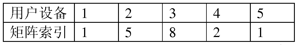
如表 2所示, 宏基站生成的用户设备 1和 5的预编码矩阵相同, 其 他的用户设备对应的预编码矩阵均不同, 其中, 预编码矩阵采用矩阵索 引表示, 在基站侧或用户设备侧均储存有该矩阵索引对应的预编码矩阵 的矩阵元素信息。
在本实施例中, 对于同一个宏小区用户设备, 在不同的情况下, 例 如在不同的位置或不同的子帧下对应不同的预编码矩阵, 对于同一个用 户对应不同的子帧采用不同的预编码矩阵。
在本实施例中, 至少有一个子帧对应的预编码矩阵与其他子帧对应 的预编码矩阵不同, 如表 3所示。
表 3
 如表 3所示, 对于子帧号位 5和 10的子帧, 对应的预编码矩阵的矩 阵索引为 5, 其余子帧对应的预编码矩阵的索引为 1。
在本实施例中, 对于不同的用户设备, 配置不同的信息, 例如由于 各个用户设备的位置不同, 使得至少有一个宏小区用户设备对应的相关 信息与其他用户设备对应的相关信息, 即子帧信息和预编码矩阵等信息 不同, 分别如表 4-广 4-3所示。 表 4-1 用户设备 1


在本实施例中, 宏基站还可根据实际需要配置与 PDCCH发送功率有 关的信息, 如每个步长的功率值和功率调整步长信息, 例如假定每个步 长对应功率值为 2dB, 则功率调制步长信息, 即步长索引 '3 ' 表示 6dB, 该参数也可以为功率调整的值。
此外, 需要说明的是, 该宏基站可以根据需求配置信息, 其中可仅 包含上述部分或全部信息, 如子帧信息、 与 PDCCH发送功率有关的信息 中, 并且还可根据需要包括其他信息, 以保证 PDCCH的接收性能。
在本实施例中, 宏基站还可决定是否将生成的预编码矩阵、 或者将 预编码矩阵以及配置的上述子帧信息等相关信息通知宏小区用户设备。
例如, 若对于基于调制参考信号 (DM-RS, Demodulation Reference Signal )解调的 PDCCH, 宏基站不需要通知宏小区用户设备包括上述预编 码矩阵、 子帧信息、 PDCCH发射功率其中之几的相关信息。 而这些信息只 是在宏基站侧使用。 在这种情况下, 无论宏基站是否对 PDCCH 的信号进 行预编码, 宏小区用户设备对 PDCCH进行盲检测, 即根据信道估计结果, 进行多天线译码。
除了上述情况, 宏基站还可通知宏小区用户设备上述相关信息。 在 这种情况下, 当宏基站是对 PDCCH 的信号进行预编码使通过天线形成的 波束的零化空间对准微小区, 和 /或使波瓣的方向对准宏小区用户设备、 在宏小区用户设备检测到 PDCCH 的信号时, 可根据获得的相关信息对该 PDCCH信号进行译码处理。
在本实施例中, 若需要通知用户设备上述相关信息时, 该宏基站可 分别将生成的预编码矩阵、 或配置的子帧信息等相关信息通知用户设备, 此外, 也可将上述相关信息通过高层信令, 如无线资源控制(RRC, Radio Resource Control ) 信令一起通知宏小区用户设备, 使得宏小区用户设 备检测到 PDCCH的信号时, 可根据获得的相关信息对该 PDCCH信号进行 正确译码。
以下以宏基站通过高层信令动态配置相关信息并通知用户设备为例 进行说明。
图 2是本发明实施例 1 中宏基站侧配置相关信息的流程图。 如图 2 所示, 包括以下步骤:
步骤 201,宏基站根据微小区的信道信息,或者根据该微小区的信道 信息以及宏小区用户设备的信道信息生成预编码矩阵;
其中, 生成预编码矩阵的方式可采用与现有类似的任一种方式, 也 可采用本发明实施例的上述方式, 此处不再赘述; 其中, 可根据包括在 信道信息中的位置信息或相位信息生成。
步骤 202,该宏基站生成至少包含上述预编码矩阵的相关信息的高层 其中, 该高层信令可为 RRC信令;
该相关信息除了包括上述信息外, 还可包括 PDCCH发射功率; 此外, 还可包括采用子帧信息, 该子帧信息可表示在哪个子帧上对
PDCCH的信号进行预编码,即用于指示是否对宏小区用户设备进行预编码 的子帧信息;
上述相关信息如表 5所示, 需要说明的是, 该宏基站可以根据需求, 仅包含其中部分或全部相关信息, 并且还可根据需要包括其他信息, 以 保证 PDCCH的接收性能。
表 5
 步骤 203,该宏基站将该高层信令向相应的宏小区用户设备,使得用
户设备获得该高层信令中包含的相关信息;
步骤 203,该宏基站将该高层信令向相应的宏小区用户设备,使得用
户设备获得该高层信令中包含的相关信息;
其中, 该宏基站可通过 PDSCH将该高层信令向宏小区用户设备发送, 但不限于此种方式, 还可采用其他方式传送高层信令。
在本实施例中, 如上所述, 上述步骤 203也可省略。
在本实施例中, 如表 5所示, 该宏基站可采用不同的指示方式来指 示上述相关信息, 以下参照表 5举例说明:
例 1, 对于 "预编码矩阵矩阵"可采用矩阵索引的方式来指示该 "预 编码矩阵矩阵", 若采用这种指示方式, 则需宏在基站侧与宏小区用户设 备侧均存储相同的矩阵元素与该矩阵索引的一一对应关系, 并且该宏基 站向宏小区用户设备通知该矩阵索引即可;
例 2, 对于"预编码矩阵矩阵"也可以为矩阵元素信息, 将该矩阵元 素信息通知相应的宏小区用户设备, 使得该用户设备可通过该矩阵元素 信息产生相应的矩阵;
其中, 该矩阵元素信息, 可包含矩阵中每个元素的值, 也可仅包括某 一信息, 例如, 对于天线阵列, 可包含相位信息 Θ , 从而可推导出矩阵 中所有元素数值 f ( e )。
例 3, 对于 "PDCCH发送功率"可以为功率调整步长信息, 例如, 假 定每个步长对应功率 2dB, 则步长索引 ' 3 ' 表示 6dB; 或者也可以为功 率调整的值。
例 4,对于"子帧信息",可以采用子帧与比特值的映射关系(bitmap ) 的方式来指示子帧, 例如, 如表 1所示, 共 10比特, 来表示对应 10个 子帧, 如子帧广子帧 10。 若比特值为 1, 表示对应的子帧根据 "预编码 矩阵"对 PDCCH的信号进行译码, 本实施例中为子帧号为 10的子帧; 而 比特值为 0, 表示对应的子帧的 PDCCH的信号的处理不基于该高层信令, 而基于小区统一配置的发送方式 PDCCH。 以 LTE系统为例, 这些子帧的 PDCCH不进行预编码处理, 而是发送分集。
由上述实施例可知, 该宏基站 (Macro cell eNB ) 可通过高层信令, 如 RRC信令来配置该宏基站进行预编码所需要的相关信息, 该相关信息 可包括预编码矩阵矩阵, 可根据实际情况确定是否将该相关信息通过高 层信令通知宏小区用户设备。 这样, 该宏基站可利用该相关信息对所调
度的宏小区用户设备的下行控制信道 (PDCCH ) 的信号进行预编码, 并且 在宏小区用户设备需要利用该相关信息的情况, 也可利用该相关信息对 进行预编码处理的 PDCCH的信号进行正确译码。
实施例 2
以下参照附图对本发明实施例 2 的干扰协调方法进行说明。 其中, 以宏基站通过高层信令配置的相关信息为例对 PDCCH 的信号进行预编码 的过程进行详细说明。
图 3是本发明实施例 2的干扰协调方法流程图。 如图 3所示, 该方 法包括:
步骤 301,宏基站根据微小区的信道信息,或者根据该微小区的信道 信息以及宏小区用户设备的信道信息生成预编码矩阵;
其中, 宏基站基于该微小区的位置信息以及宏小区用户设备的位置 信息生成该相关信息, 该信道信息可包括位置信息或相位信息, 生成的 方法如实施例 1所述, 此处不再赘述。
步骤 302,该宏基站生成至少包含上述预编码矩阵在内的相关信息的 高层信令, 使得宏小区用户设备可根据上述相关信息对检测到的 PDCCH 进行正确译码;
该相关信息除了包括上述信息外, 还包括子帧信息, 该子帧信息可 表示在哪个子帧上对 PDCCH 的信号进行预编码, 即用于指示是否对宏小 区用户设备进行预编码的子帧信息;
例如, 如表 4-广表 4-3所示, 对于不同的用户设备, 其对应的矩阵 可相同或不同, 对应的子帧信息可相同或不同;
需要说明的是, 该宏基站可以根据需求, 还可根据需要包括其他信 息, 以保证 PDCCH的接收性能。
步骤 303,该宏基站将该高层信令通知相应的宏小区用户设备,使得 用户设备获得该高层信令中包含的相关信息;
例如, 通知的信息如表 3所示, 其中矩阵采用矩阵索引的方式指示, 这样, 该微小区还需要将该矩阵元素与矩阵索引的对应关系通知用户设 备, 并在该宏基站和宏小区用户设备侧储存。
这样, 该宏基站可根据高层信令配置的上述信息对 PDCCH的信号进
行多天线处理。
步骤 304,在宏基站调度宏小区的多个用户设备时,宏基站生成所调 度的宏小区用户设备的下行控制信道的信号;
其中, 生成的过程与现有技术类似, 其中, 该宏基站可根据各个用 户的传输模式生成相应的下行控制信息 DCI ; 对该 DCI进行调制编码、 复 用加扰。
步骤 305,该宏基站根据上述步骤 30广 302配置的高层信令,判断是 否对所调度的宏小区用户设备的下行控制信道的信号进行预编码, 以使 通过预编码形成的信号零化空间对准微小区、 和 /或使信号的强功率方向 或特征值空间对准宏小区用户设备; 若判断结果为是, 则执行步骤 306, 否则执行步骤 307;
其中, 该宏基站可根据表 3的配置的子帧信息进行判断, 具体包括: 若根据该子帧信息确定当前子帧为对 PDCCH的信号进行预编码的子 帧, 则该宏基站确定利用生成的预编码矩阵对所调度的宏小区用户设备 的下行控制信道的信号进行预编码, 使通过预编码形成的信号零化空间 对准微小区、 和 /或使信号的强功率方向或特征值空间对准宏小区用户设 备; 否则不进行预编码, 而采用系统配置的多天线方式对 PDCCH 的信号 进行发送分集;
其中, 如表 4-1所示, 对于宏小区的用户设备 1, 若当前子帧号为第 5个子帧, 则可确定不采用配置的高层信令对 PDCCH的信号进行处理, 执 行步骤 307; 若当前子帧号为 10, 则采用配置的高层信息对 PDCCH的信 号进行处理, 则执行步骤 306;
类似, 如表 4-2, 表 4-3所示, 可根据当前子帧信息来判断是否采用 配置的高层信令对 PDCCH的信号进行处理, 此处不再赘述。
步骤 306,在步骤 305的判断结果为是时,该宏基站可根据生成的预 编码矩阵对 PDCCH 的信号进行预编码处理, 使得通过预编码形成的信号 零化空间对准微小区、 和 /或使信号的强功率方向或特征值空间对准宏小 区用户设备;
在使用阵列天线的情况下, 使得通过天线形成的波束的零化空间对 准微小区、 和 /或使波瓣的方向对准宏小区用户设备;
其中, 如表 4-1, 对于用户设备 1, 矩阵以矩阵索引的方式表示, 如 矩阵索引 5, 这样, 宏基站可根据该矩阵索引号 5找到相应的矩阵, 对该 用户设备 1 的 PDCCH的信号进行处理, 使得通过预编码形成的信号零化 空间对准微小区、 和 /或使信号的强功率方向或特征值空间对准宏小区用 户设备。
步骤 307, 在步骤 305中, 若判断结果为否, 则按照系统配置的多天 线方式对 PDCCH的信号进行发送分集;
其中, 如表 4-1, 对于用户设备 1, 若当前子帧号为 5, 则宏基站按 照系统配置的多天线方式对该用户设备 1的 PDCCH的信号进行发送分集。
在上述实施例中, 是以表 4-广 4-3为例进行了说明, 这样需要在对
PDCCH的信号进行处理之前执行判断步骤 305, 若宏基站通过高层信令配 置的信息为其他情况时, 如对于所有的用户设备均进行预编码处理, 则 可省略该步骤 305和步骤 307, 上述仅为本发明实施例而已。
由上述实施例可知, 该宏基站 (Macro cell eNB ) 可通过高层信令, 如 RRC信令来配置该宏基站进行预编码所需要的相关信息, 将该相关信 息通知宏小区用户设备。 这样, 该宏基站可利用该相关信息对所调度的 宏小区用户设备的下行控制信道 (PDCCH ) 的信号进行预编码, 以使通过 预编码形成的信号零化空间对准微小区、 和 /或使信号的强功率方向或特 征值空间对准宏小区用户设备, 从而消除了宏基站的 PDCCH 的信号对微 小区的干扰, 避免了基站性能的下降, 解决了现有技术中存在的问题; 或者不仅提高宏小区用户设备的接收性能, 还能进一步消除宏小区对微 小区的干扰。
实施例 3
本发明实施例提供一种干扰协调方法, 如图 4所示, 该方法包括: 步骤 401,宏小区用户设备检测下行控制信道的信号,该下行控制信 道的信号由宏基站进行预编码, 使通过预编码形成的信号零化空间对准 微小区、 和 /或使信号的强功率方向或特征值空间对准宏小区用户设备; 其中, 宏小区用户设备在每个子帧中盲检测 PDCCH的信号; 步骤 402,该宏小区用户设备根据信道估计结果,或者根据预先获得 的包括预编码矩阵在内的相关信息对该信号进行译码。
在本实施例中, 该相关信息除了包括预编码矩阵外, 还可包括其他 信息, 如实施例 1和 2所述, 此处不再赘述。
在本实施例中, 在某些情况下不需要用户设备获知上述相关信息, 并利用上述相关信息进行相应的译码, 如实施例 1 中所述, 此处不再赘 述。 在这种情况下, 在步骤 402 中该宏小区用户设备即可根据信道估计 结果进行多天线译码。
此外, 在需要用到该相关信息的情况下, 该宏小区用户设备可根据 该相关信息对该 PDCCH的信号进行译码。
在本实施例中, 在步骤 402之后, 还可包括以下步骤:
该宏小区用户设备可对该译码后的信号进行相应的解扰、 解调和信 道译码、 CRC校验, 最终获得相应的信息; 其中, 可采用现有的任意一种 方式进行处理此处不再赘述。
由上述实施例可知, 宏小区用户设备可根据宏基站配置的相关信息 对检测到的 PDCCH的信号进行正确处理。
在本实施例中, 在该宏小区用户设备盲检测之前, 还可包括步骤: 接收宏基站通知的相关信息, 此外还将该相关信息进行储存。 其中, 该 相关信息的内容如实施例 2所述, 此处不再赘述。
这样, 若该相关信息包括子帧信息时, 如表 1 所示, 则在步骤 402 之前还可包括步骤: 确定是否根据宏基站配置的矩阵对该下行控制信道 的信号进行译码; 其中, 例如如表 1 所示, 若宏小区用户设备确定当前 子帧为宏基站采用高层信令配置的矩阵进行预编码处理所对应的子帧, 则该用户设备可确定根据宏基站配置的矩阵对 PDCCH 的信号进行译码; 否则按照系统配置的多天线方式对 PDCCH的信号进行多天线译码。
实施例 4
以下结合附图 5、表 1和 2的信息对宏小区的用户设备 UE接收 PDCCH 的流程进行说明。 其中, 以用户设备需要利用宏基站配置的相关信息为 例进行说明。
本发明实施例提供一种干扰协调方法, 如图 5所示, 该方法包括: 步骤 501,宏小区用户设备接收宏基站通知的相关信息,此外还将该 相关信息进行储存;
其中, 该相关信息的配置过程如实施例 1和图 2所述, 此处不再赘 述, 例如可配置如表 1-表 5所示的信息。
步骤 502, 宏小区用户设备在每个子帧中盲检测 PDCCH的信号; 步骤 503,判断当前子帧是否为宏基站采用高层信令配置的预编码矩 阵进行预编码处理所对应的子帧; 若判断结果为是则执行步骤 504; 否则 执行步骤 507;
步骤 504,该宏小区用户设备根据该宏基站通知的相关信息中的预编 码矩阵矩阵对该信号进行译码;
步骤 505, 对进行译码后的信号进行解扰、 信道译码;
步骤 506,对信道译码后的信号进行 CRC校验,最终获得该下行控制 信息。
步骤 507, 若在步骤 503中, 判断结果为否, 则该宏基站按照系统配 置的多天线方式对 PDCCH的信号进行多天线译码;
然后执行步骤 508〜509, 对译码后的信号进行解扰、信道译码, 并且 对信道译码后的信号进行 CRC校验, 最终获得下行控制信息。
在本实施例中, 该步骤 508〜509的处理过程与步骤 505〜506的过程 类似, 可采用现有的任何一种方式进行处理, 此处不再赘述。
由上述实施例可知, 该宏基站 (Macro cell eNB ) 可通过高层信令, 如 RRC信令来配置该宏基站进行预编码所需要的相关信息, 将该相关信 息通知宏小区用户设备。 这样, 该宏基站可利用该相关信息对所调度的 宏小区用户设备的下行控制信道 (PDCCH ) 的信号进行预编码, 以使通过 预编码形成的信号零化空间对准微小区、 和 /或使信号的强功率方向或特 征值空间对准宏小区用户设备, 从而使得宏小区用户设备可根据宏基站 配置的相关信息对检测到的 PDCCH的信号进行正确处理。
本发明实施例还提供了一种宏基站和用户设备, 如下面的实施例 4、
5和 6所述。 由于该宏基站和用户设备解决问题的原理与上述实施例 1-3 的基于宏基站和用户设备的干扰协调方法相似, 因此该宏基站和用户设 备的实施可以参见方法的实施, 重复之处不再赘述。
实施例 5
本发明实施例提供一种宏基站, 如图 6所示, 该基站包括第一信号
处理单元 601和天线单元 602 ; 其中,
第一信号处理单元 601用于利用预先获得的预编码矩阵对所调度的 宏小区用户设备的下行控制信道的信号进行预编码;
天线单元 602,用于发射进行预编码的信号,使通过预编码形成的信 号零化空间对准微小区、 和 /或使信号的强功率方式 /特征值空间方向对 准宏小区用户设备。
其中, 该天线单元 602可为强相关性的自适应天线阵列, 也可为相 关性较弱的极化天线等。
由上述实施例可知, 该宏基站可利用获得的预编码矩阵对所调度的 宏小区用户设备的下行控制信道 (PDCCH ) 的信号进行预编码, 以使通过 预编码形成的信号零化空间对准微小区、 和 /或使信号的强功率方向 /特 征值空间的方向对准宏小区用户设备, 以消除宏小区对微小区的干扰, 并且宏小区的性能不会受到影响; 此外还可提高用户设备的接收性能。
此外, 该宏基站还可包括控制信息生成单元(未示出), 该控制信息 生成单元用于生成所调度的宏小区用户设备的下行控制信道的信号; 其 中, 生成 PDCCH信号的过程与实施例 2中步骤 304类似, 此处不再赘述。 并且第一信号处理单元 601可对该控制信息生成单元生成的 PDCCH的信 号进行预编码处理, 即可将该 PDCCH 的信号与预编码矩阵相乘, 然后通 过天线单元 602 发射出去, 使通过预编码形成的信号零化空间对准微小 区、 和 /或使信号的强功率方向或特征值空间对准宏小区用户设备。
由上述实施例可知, 通过上述预编码处理, 通过使信号的零化空间 对准为小区, 可避免, 甚至消除了宏小区 (Macro cell) 的物理下行控制 信道 PDCCH对微小区 Pico cell的干扰, 并且对宏小区的性能不会产生 影响, 解决了现有技术中存在的问题。 此外, 通过上述预编码处理, 通 过使信号的强功率方向对准宏小区用户设备, 还可进一步提高宏小区用 户设备的接收性能, 并且更进一步减轻宏基站微小区的干扰。
实施例 6
基于实施例 5, 在本发明实施例中, 该宏基站还可生成预编码矩阵, 并且还可配置包括子帧信息在内的相关信息, 即可供该宏基站使用, 有 可在用户设备需要的情况下, 通过高层信令, 如 RRC信令将上述相关信
息一起通知宏小区用户设备。 这样, 该宏基站可利用该相关信息对所调 度的宏小区用户设备的下行控制信道 (PDCCH ) 的信号进行预编码, 并且 宏小区用户设备也可利用该相关信息对进行预编码处理的 PDCCH 的信号 进行正确译码。
这样, 在本实施例中, 如图 7所示, 该宏基站包括控制信息生成单 元 701、第一信号处理单元 702和天线单元 703,其作用于实施例 4类此, 此处不再赘述。
此外, 还可包括: 矩阵生成单元 704和储存单元 705;
其中, 矩阵生成单元 704用于在根据该微小区的信道信息, 或者根 据该微小区的信道信息以及宏小区用户设备的信道信息生成预编码矩 阵; 其中, 具体的生成过程如实施例 1所述。
储存单元 705,用于储存该预编码矩阵的矩阵元素信息,或者将该预 编码矩阵的矩阵元素与矩阵索弓 I对应储存。
此外, 该宏基站还可配置指示是否对宏小区用户设备进行预编码使 通过预编码形成的信号零化空间对准微小区、 和 /或使信号的强功率方向 或特征值空间对准宏小区用户设备的子帧信息。 这样, 该宏基站还可包 括: 信息配置单元 706和第一确定单元 707 ; 其中,
信息配置单元 706,用于配置指示是否对宏小区用户设备进行预编码 使通过预编码形成的信号零化空间对准微小区、 和 /或使信号的强功率方 向或特征值空间对准宏小区用户设备的子帧信息; 并且存储单元 705 也 可存储该子帧信息;
并且第一确定单元 707,用于在第一信号处理单元 702对该宏基站对 所调度的宏小区用户设备的下行控制信道的信号进行预编码之前, 根据 子帧信息确定当前子帧是否为对下行控制信道的信号进行预编码, 使通 过预编码形成的信号零化空间对准微小区、 和 /或使信号的强功率方向或 特征值空间对准宏小区用户设备的子帧;
并且第一信号处理单元 702用于在第一确定单元 707的确定结果为 是时, 对所调度的宏小区用户设备的下行控制信道的信号进行预编码, 使通过预编码形成的信号零化空间对准微小区、 和 /或使信号的强功率方 向或特征值空间对准宏小区用户设备。
除了配置上述子帧信息外, 还可配置其他信息, 如实施例 1-4所述, 此处不再赘述。
在本实施例中, 在需要的情况下, 即实施例 1 中所述的情况, 该宏 基站还可将配置的上述信息、 以及生成的预编码矩阵通过高层控制信令 通知宏小区用户设备, 但不限于高层控制信令, 还可采用其他信令进行 通知。
如图 7所示,该宏基站还可包括信息通知单元 708,用于将该相关信 息通知宏小区用户设备; 并且, 在这种情况下, 第一信号处理单元 702 利用该相关信息对控制信息生成单元 701产生的信号进行预编码。
在上述实施例中, 该宏基站的解决问题的原理与实施例 1和 2类似, 此处不再赘述。
实施例 7
本发明实施例提供一种用户设备, 如图 8所示, 该用户设备包括: 信号检测单元 801,用于检测下行控制信道的信号,该下行控制信道 的信号由宏基站进行预编码, 使通过预编码形成的信号零化空间对准微 小区、 和 /或使信号的强功率方向或特征值空间对准宏小区用户设备; 第二信号处理单元 802,用于根据信道估计结果,或者根据预先获得 的包括预编码矩阵在内的相关信息对所述信号检测单元检测到的信号进 行译码。
此外, 还可包括信号处理单元(未示出), 用于对译码后的信号进行 相应的处理, 即解扰、 信号译码和 CRC校验, 以最终获得下行控制信息。
在本实施例中, 宏基站还可根据宏小区用户设备对 PDCCH进行解调 的方式来决定是否将生成的预编码矩阵、 或者将预编码矩阵以及配置的 上述子帧信息等相关信息通知宏小区用户设备。
例如, 若对于基于调制参考信号 (DM-RS, Demodulation Reference
Signal )解调的 PDCCH, 宏基站不需要通知宏小区用户设备包括上述预编 码矩阵、 子帧信息、 PDCCH发射功率其中之几的相关信息。 而这些信息只 是在宏基站侧使用。 在这种情况下, 无论宏基站是否对 PDCCH 的信号进 行预编码, 宏小区用户设备对 PDCCH进行盲检测, 即根据信道估计结果, 进行多天线译码。
除了上述情况, 宏基站还可通知宏小区用户设备上述相关信息。 在 这种情况下, 当宏基站是对 PDCCH 的信号进行预编码使通过预编码形成 的信号零化空间对准微小区、 和 /或使信号的强功率方向或特征值空间对 准宏小区用户设备, 当宏小区用户设备检测到 PDCCH 的信号, 可根据获 得的相关信息对该 PDCCH信号进行解码处理。
在本实施例中, 若需要通知用户设备上述相关信息时, 该宏基站可 分别将生成的预编码矩阵、 或配置的子帧信息等相关信息通知用户设备, 此外, 也可将上述相关信息通过高层信令, 如无线资源控制(RRC, Radio Resource Control ) 信令一起通知宏小区用户设备, 使得宏小区用户设 备检测到 PDCCH的信号时, 可根据获得的相关信息对该 PDCCH信号进行 正确译码。
在本发明实施例中, 如图 8所示, 该用户设备还可包括: 信息接收 单元 803, 用于接收该宏基站通知的相关信息, 其中, 该相关信息的内容 如实施例 2中所述, 此处不再赘述。
此外,该用户设备还可包括存储单元 804,用于储存接收到的相关信 息, 以供第二信号处理单元 802利用。
在本实施例中, 若相关信息包含如表 1或表 3中的子帧信息, 则该 第二信号处理单元 802 在对检测到的信号进行译码之前, 还需要根据当 前子帧和该子帧信息判断是否对检测到的信号按照宏基站配置的高层信 令进行译码, 具体的判断方式如上所述, 此处不再赘述。 这样, 该用户 设备还可包括第二确定单元 (未示出), 用于确定是否对检测到的 PDCCH 的信号按照宏基站配置的高层信令进行译码。
在上述实施例中, 该用户设备的解决问题的原理与实施例 3类似, 此处不再赘述。
在本实施例中, 该宏小区用户设备不限于移动电话, 而可以涉及任 何类型的适当的电子设备, 其示例包括媒体播放器、 游戏设备、 桌上型 或膝上型计算机, 寻呼机、 通信器、 个人数字助理 (PDA)、 智能电话等 发送数据并接收对所发送的数据的反馈的所有设备。
通过上述实施例, 该宏基站 (Macro cell eNB ) 可通过高层信令, 如 RRC信令来配置该宏基站进行预编码所需要的相关信息,将该相关信息通
知宏小区用户设备。 这样, 该宏基站可利用该相关信息对所调度的宏小 区用户设备的下行控制信道 (PDCCH) 的信号进行预编码, 以使通过预编 码形成的信号零化空间对准微小区可避免, 甚至消除了宏小区 (Macro cell) 的物理下行控制信道 PDCCH对微小区 (Pico cell) 的干扰;、 和 / 或使信号的特征值空间对准宏小区用户设备, 既可提高用户设备的接收 性能有可进行干扰协调; 并且还使得宏小区用户设备可根据宏基站配置 的相关信息对检测到的 PDCCH的信号进行正确处理。
本发明实施例还提供一种计算机可读程序, 其中当在宏基站中执行 该程序时, 该程序使得计算机在该宏基站中执行如实施例 1或 2的干扰 协调方法。
本发明实施例还提供一种存储有计算机可读程序的存储介质, 其中 该计算机可读程序使得计算机在宏基站中执行如实施例 1或 2的干扰协 调方法。
本发明实施例还提供一种计算机可读程序, 其中当在用户设备中执 行所述程序时, 该程序使得计算机在该用户设备中执行如实施例 3 或 4 的干扰协调方法。
本发明实施例还提供一种存储有计算机可读程序的存储介质, 其中 该计算机可读程序使得计算机在用户设备中执行如实施例 3或 4的干扰 协调方法。
本发明以上的装置和方法可以由硬件实现, 也可以由硬件结合软件 实现。 本发明涉及这样的计算机可读程序, 当该程序被逻辑部件所执行 时, 能够使该逻辑部件实现上文所述的装置或构成部件, 或使该逻辑部 件实现上文所述的各种方法或步骤。 本发明还涉及用于存储以上程序的 存储介质, 如硬盘、 磁盘、 光盘、 DVD、 flash存储器等。
以上结合具体的实施方式对本发明进行了描述, 但本领域技术人员 应该清楚, 这些描述都是示例性的, 并不是对本发明保护范围的限制。 本领域技术人员可以根据本发明的精神和原理对本发明做出各种变型和 修改, 这些变型和修改也在本发明的范围内。
Claims
1、 一种干扰协调方法, 所述方法包括:
宏基站利用预先获得的预编码矩阵对所调度的宏小区用户设备的下 行控制信道的信号进行预编码, 使通过预编码形成的信号零化空间对准 微小区、和 /或使信号的强功率方向 /特征值空间对准所述宏小区用户设备。
2、 根据权利要求 1所述的方法, 其中, 在宏基站对所调度的宏小区 用户设备的下行控制信道的信号进行预编码之前, 所述方法还包括: 所述宏基站根据所述微小区的信道信息, 或者根据所述微小区的信 道信息以及宏小区用户设备的信道信息生成所述预编码矩阵;
储存所述预编码矩阵的矩阵元素信息, 或者将所述预编码矩阵的矩 阵元素与矩阵索引对应储存。
3、 根据权利要求 1所述的方法, 其中, 所述方法还包括:
配置指示是否对宏小区用户设备进行预编码使通过预编码形成的信 号零化空间对准微小区、 和 /或使信号的强功率方向 /特征值空间对准所 述宏小区用户设备的子帧信息;
并且在所述宏基站对所调度的宏小区用户设备的下行控制信道的信 号进行预编码之前, 所述方法还包括:
根据所述子帧信息确定当前子帧是否为对下行控制信道的信号进行 预编码, 使通过预编码形成的信号零化空间对准微小区、 和 /或使信号的 强功率方向 /特征值空间对准所述宏小区用户设备的子帧;
若确定结果为是, 则所述宏基站确定对所调度的宏小区用户设备的 下行控制信道的信号进行预编码, 使通过预编码形成的信号零化空间对 准微小区、 和 /或使信号的强功率方向 /特征值空间对准所述宏小区用户 设备。
4、 根据权利要求 1所述的方法, 其中, 至少有一个宏小区用户设备 的预编码矩阵与其他宏小区用户设备的预编码矩阵不同; 或者
对于同一个宏小区用户设备, 在不同的情况下对应不同的预编码矩 阵; 或者
至少有一个子帧对应的预编码矩阵与其他子帧对应的预编码矩阵不同。
5、根据权利要求权利要求 2或 3所述的方法,其中,所述方法还包括: 将所述预编码矩阵的矩阵元素信息, 或者将所述矩阵索引通知相应 的宏小区用户设备; 将配置的所述子帧信息通知相应的宏小区用户设备。
6、 一种干扰协调方法, 所述方法包括:
宏小区用户设备检测下行控制信道的信号, 所述下行控制信道的信 号由宏基站进行预编码, 使通过预编码形成的信号零化空间对准微小区、 和 /或使信号的强功率方向 /特征值空间对准所述宏小区用户设备;
所述宏小区用户设备根据信道估计结果, 或者根据预先获得的包括 预编码矩阵在内的相关信息对所述信号进行译码。
7、 根据权利要求 6所述的方法, 其中, 所述方法还包括: 接收所述 宏基站通知的所述相关信息。
8、 根据权利要求 6所述的方法, 其中, 所述相关信息还包括指示是 否对宏小区用户设备进行预编码使通过预编码形成的信号零化空间对准 微小区、 和 /或使信号的强功率方向 /特征值空间对准所述宏小区用户设 备的子帧信息;
并且在根据预先获得的包括预编码矩阵在内的相关信息对所述信号 进行译码之前, 所述方法还包括:
根据所述子帧信息确定是否根据所述相关信息对所述下行控制信道 的信号进行译码。
9、 一种宏基站, 所述宏基站包括:
第一信号处理单元, 用于利用预先获得的预编码矩阵对所调度的宏 小区用户设备的下行控制信道的信号进行预编码;
天线单元, 用于发射进行预编码的信号, 使通过所述天线单元形成 的信号的零化空间对准微小区、 和 /或使信号的强功率方向 /特征值空间 对准所述宏小区用户设备。
10、 根据权利要求 9所述的宏基站, 其中, 所述宏基站还包括: 矩阵生成单元, 用于在根据所述微小区的信道信息, 或者根据所述 微小区的信道信息以及宏小区用户设备的信道信息生成所述预编码矩阵; 储存单元, 用于储存所述预编码矩阵的矩阵元素信息, 或者将所述 预编码矩阵的矩阵元素与矩阵索弓 I对应储存。
11、 根据权利要求 9所述的宏基站, 其中, 所述宏基站还包括: 信息配置单元, 用于配置指示是否对宏小区用户设备进行预编码使 通过预编码形成的信号零化空间对准微小区、 和 /或使信号的强功率方向 /特征值空间对准所述宏小区用户设备的子帧信息;
并且所述宏基站还包括:
第一确定单元, 用于在所述宏基站对所调度的宏小区用户设备的下 行控制信道的信号进行预编码之前, 根据所述子帧信息确定当前子帧是 否为对下行控制信道的信号进行预编码, 使通过预编码形成的信号零化 空间对准微小区、 和 /或使信号的强功率方向 /特征值空间对准所述宏小 区用户设备的子帧;
并且所述第一信号处理单元用于在所述第一确定单元的确定结果为 是时, 对所调度的宏小区用户设备的下行控制信道的信号进行预编码, 使通过预编码形成的信号零化空间对准微小区、 和 /或使信号的强功率方 向 /特征值空间对准所述宏小区用户设备。
12、 根据权利要求 9所述的宏基站, 其中, 至少有一个宏小区用户 设备的预编码矩阵与其他宏小区用户设备的预编码矩阵不同; 或者对于 同一个宏小区用户设备, 在不同的情况下对应不同的预编码矩阵; 或者 至少有一个子帧对应的预编码矩阵与其他子帧对应的预编码矩阵不同。
13、 一种用户设备, 所述用户设备包括:
信号检测单元, 用于检测下行控制信道的信号, 所述下行控制信道 的信号由宏基站进行预编码, 使通过预编码形成的信号零化空间对准微 小区、 和 /或使信号的强功率方向 /特征值空间对准所述宏小区用户设备; 第二信号处理单元, 用于根据信道估计结果, 或者根据预先获得的 包括预编码矩阵在内的相关信息对所述信号检测单元检测到的信号进行 译码。
14、 根据权利要求 13所述的用户设备, 其中, 所述相关信息还包括 指示是否对宏小区用户设备进行预编码使通过预编码形成的信号零化空 间对准微小区、 和 /或使信号的强功率方向 /特征值空间对准所述宏小区 用户设备的子帧信息;
所述用户设备还包括:
第二确定单元, 所述第二确定单元用于根据所述子帧信息确定是否 根据所述相关信息对所述下行控制信道的信号进行译码。
15、 一种计算机可读程序, 其中当在宏基站中执行所述程序时, 所 述程序使得计算机在所述宏基站中执行如权利要求 1至 5的任一项权利 要求所述的干扰协调方法。
16、 一种存储有计算机可读程序的存储介质, 其中所述计算机可读 程序使得计算机在宏基站中执行如权利要求 1至 5的任一项权利要求所 述的干扰协调方法。
17、 一种计算机可读程序, 其中当在用户设备中执行所述程序时, 所述程序使得计算机在所述用户设备中执行如权利要求 6至 8的任一项 权利要求所述的干扰协调方法。
18、 一种存储有计算机可读程序的存储介质, 其中所述计算机可读 程序使得计算机在用户设备中执行如权利要求 6至 8的任一项权利要求 所述的干扰协调方法。
Priority Applications (6)
| Application Number | Priority Date | Filing Date | Title |
|---|---|---|---|
| EP11860151.7A EP2685643A4 (en) | 2011-03-10 | 2011-03-10 | INTERFERENCE COORDINATION PROCEDURE, BASIC STATION AND USER DEVICE |
| PCT/CN2011/071677 WO2012119314A1 (zh) | 2011-03-10 | 2011-03-10 | 干扰协调方法、基站和用户设备 |
| KR1020137026025A KR101610452B1 (ko) | 2011-03-10 | 2011-03-10 | 간섭 조정 방법, 기지국 및 사용자 단말기 |
| JP2013556945A JP5780316B2 (ja) | 2011-03-10 | 2011-03-10 | 干渉協調方法、基地局及びユーザー機器 |
| CN201180069022.8A CN103404052B (zh) | 2011-03-10 | 2011-03-10 | 干扰协调方法、基站和用户设备 |
| US14/022,841 US9225484B2 (en) | 2011-03-10 | 2013-09-10 | Interference coordinating method, base station and user equipment |
Applications Claiming Priority (1)
| Application Number | Priority Date | Filing Date | Title |
|---|---|---|---|
| PCT/CN2011/071677 WO2012119314A1 (zh) | 2011-03-10 | 2011-03-10 | 干扰协调方法、基站和用户设备 |
Related Child Applications (1)
| Application Number | Title | Priority Date | Filing Date |
|---|---|---|---|
| US14/022,841 Continuation US9225484B2 (en) | 2011-03-10 | 2013-09-10 | Interference coordinating method, base station and user equipment |
Publications (1)
| Publication Number | Publication Date |
|---|---|
| WO2012119314A1 true WO2012119314A1 (zh) | 2012-09-13 |
Family
ID=46797421
Family Applications (1)
| Application Number | Title | Priority Date | Filing Date |
|---|---|---|---|
| PCT/CN2011/071677 Ceased WO2012119314A1 (zh) | 2011-03-10 | 2011-03-10 | 干扰协调方法、基站和用户设备 |
Country Status (6)
| Country | Link |
|---|---|
| US (1) | US9225484B2 (zh) |
| EP (1) | EP2685643A4 (zh) |
| JP (1) | JP5780316B2 (zh) |
| KR (1) | KR101610452B1 (zh) |
| CN (1) | CN103404052B (zh) |
| WO (1) | WO2012119314A1 (zh) |
Cited By (3)
| Publication number | Priority date | Publication date | Assignee | Title |
|---|---|---|---|---|
| CN103701570A (zh) * | 2013-11-29 | 2014-04-02 | 北京邮电大学 | 异构网络下收发机的设计方法 |
| CN104469688A (zh) * | 2013-09-22 | 2015-03-25 | 中国移动通信集团公司 | 一种预编码的方法、设备和系统 |
| WO2016026107A1 (zh) * | 2014-08-20 | 2016-02-25 | 华为技术有限公司 | 一种无线通信方法、装置及基站 |
Families Citing this family (19)
| Publication number | Priority date | Publication date | Assignee | Title |
|---|---|---|---|---|
| US11394436B2 (en) | 2004-04-02 | 2022-07-19 | Rearden, Llc | System and method for distributed antenna wireless communications |
| US11451275B2 (en) | 2004-04-02 | 2022-09-20 | Rearden, Llc | System and method for distributed antenna wireless communications |
| US11190947B2 (en) | 2014-04-16 | 2021-11-30 | Rearden, Llc | Systems and methods for concurrent spectrum usage within actively used spectrum |
| US10194346B2 (en) | 2012-11-26 | 2019-01-29 | Rearden, Llc | Systems and methods for exploiting inter-cell multiplexing gain in wireless cellular systems via distributed input distributed output technology |
| US11189917B2 (en) | 2014-04-16 | 2021-11-30 | Rearden, Llc | Systems and methods for distributing radioheads |
| US11050468B2 (en) * | 2014-04-16 | 2021-06-29 | Rearden, Llc | Systems and methods for mitigating interference within actively used spectrum |
| US10164698B2 (en) | 2013-03-12 | 2018-12-25 | Rearden, Llc | Systems and methods for exploiting inter-cell multiplexing gain in wireless cellular systems via distributed input distributed output technology |
| US10547358B2 (en) | 2013-03-15 | 2020-01-28 | Rearden, Llc | Systems and methods for radio frequency calibration exploiting channel reciprocity in distributed input distributed output wireless communications |
| CN103929781B (zh) * | 2014-04-09 | 2017-02-15 | 东南大学 | 超密集异构网络下跨层干扰协调优化方法 |
| US11290162B2 (en) | 2014-04-16 | 2022-03-29 | Rearden, Llc | Systems and methods for mitigating interference within actively used spectrum |
| CN103957529B (zh) * | 2014-04-17 | 2017-08-01 | 北京理工大学 | 一种基于学习的无定形小区的多准则用户选择方法 |
| CN104410977B (zh) * | 2014-12-02 | 2018-01-30 | 华中科技大学 | 一种基于认知学习的同频异构网络广播信道干扰管理方法 |
| WO2017107002A1 (en) * | 2015-12-21 | 2017-06-29 | Orange | Method and device for beamforming |
| KR102511694B1 (ko) * | 2016-07-13 | 2023-03-20 | 삼성전자 주식회사 | 무선 통신 시스템에서 슬라이딩 윈도우 중첩 코딩 전송을 위한 시그널링 방법 및 장치 |
| CN107070581B (zh) * | 2016-12-29 | 2019-10-25 | 上海华为技术有限公司 | 一种干扰消除方法以及基站 |
| CN109819523B (zh) * | 2017-11-20 | 2022-03-29 | 中国电信股份有限公司 | 通信方法以及通信系统 |
| EP3881443A4 (en) * | 2018-11-16 | 2022-07-20 | CommScope Technologies LLC | INTERFERENCE SUPPRESSION FOR MU-MIMO PRE-CODERS (MULTI-INPUT/MULTI-USER MULTI-OUTPUT) USING COORDINATION BETWEEN ONE OR MORE RADIO POINTS |
| FI129139B (en) * | 2020-01-15 | 2021-08-13 | Nokia Technologies Oy | Wireless location detection |
| US11611379B2 (en) * | 2020-05-13 | 2023-03-21 | Qualcomm Incorporated | Precoding techniques for wireless communications |
Citations (3)
| Publication number | Priority date | Publication date | Assignee | Title |
|---|---|---|---|---|
| WO2010019015A2 (en) * | 2008-08-14 | 2010-02-18 | Electronics And Telecommunications Research Institute | Method to generate beamforming vector and provide the information for generating beamforming vector |
| CN101662320A (zh) * | 2008-08-25 | 2010-03-03 | 华为技术有限公司 | 一种预编码方法、装置及通信系统 |
| CN101908948A (zh) * | 2010-07-15 | 2010-12-08 | 中国科学技术大学 | 一种基于特征子信道的干扰对齐预编码矩阵优化方法 |
Family Cites Families (4)
| Publication number | Priority date | Publication date | Assignee | Title |
|---|---|---|---|---|
| US8447236B2 (en) * | 2008-05-15 | 2013-05-21 | Qualcomm Incorporated | Spatial interference mitigation schemes for wireless communication |
| JP5244631B2 (ja) * | 2009-01-22 | 2013-07-24 | 京セラ株式会社 | 無線装置および無線通信方法 |
| US8938247B2 (en) * | 2009-04-23 | 2015-01-20 | Qualcomm Incorporated | Sounding reference signal for coordinated multi-point operation |
| JP5581230B2 (ja) * | 2011-01-07 | 2014-08-27 | 株式会社Nttドコモ | 無線基地局装置及び無線通信方法 |
-
2011
- 2011-03-10 EP EP11860151.7A patent/EP2685643A4/en not_active Withdrawn
- 2011-03-10 JP JP2013556945A patent/JP5780316B2/ja not_active Expired - Fee Related
- 2011-03-10 CN CN201180069022.8A patent/CN103404052B/zh not_active Expired - Fee Related
- 2011-03-10 WO PCT/CN2011/071677 patent/WO2012119314A1/zh not_active Ceased
- 2011-03-10 KR KR1020137026025A patent/KR101610452B1/ko not_active Expired - Fee Related
-
2013
- 2013-09-10 US US14/022,841 patent/US9225484B2/en not_active Expired - Fee Related
Patent Citations (3)
| Publication number | Priority date | Publication date | Assignee | Title |
|---|---|---|---|---|
| WO2010019015A2 (en) * | 2008-08-14 | 2010-02-18 | Electronics And Telecommunications Research Institute | Method to generate beamforming vector and provide the information for generating beamforming vector |
| CN101662320A (zh) * | 2008-08-25 | 2010-03-03 | 华为技术有限公司 | 一种预编码方法、装置及通信系统 |
| CN101908948A (zh) * | 2010-07-15 | 2010-12-08 | 中国科学技术大学 | 一种基于特征子信道的干扰对齐预编码矩阵优化方法 |
Non-Patent Citations (1)
| Title |
|---|
| VIVECK R. CADAMBE ET AL.: "Interference Alignment and Spatial Degrees of Freedom for the K User Interference Channel", IEEE TRANSACTION INFORMATION THEORY, vol. 54, no. IS.8, August 2008 (2008-08-01), pages 3425 - 3441, XP011231331 * |
Cited By (7)
| Publication number | Priority date | Publication date | Assignee | Title |
|---|---|---|---|---|
| CN104469688A (zh) * | 2013-09-22 | 2015-03-25 | 中国移动通信集团公司 | 一种预编码的方法、设备和系统 |
| CN104469688B (zh) * | 2013-09-22 | 2018-10-26 | 中国移动通信集团公司 | 一种预编码的方法、设备和系统 |
| CN103701570A (zh) * | 2013-11-29 | 2014-04-02 | 北京邮电大学 | 异构网络下收发机的设计方法 |
| CN103701570B (zh) * | 2013-11-29 | 2019-01-22 | 北京邮电大学 | 异构网络下收发机的设计方法 |
| WO2016026107A1 (zh) * | 2014-08-20 | 2016-02-25 | 华为技术有限公司 | 一种无线通信方法、装置及基站 |
| CN106576328A (zh) * | 2014-08-20 | 2017-04-19 | 华为技术有限公司 | 一种无线通信方法、装置及基站 |
| CN106576328B (zh) * | 2014-08-20 | 2019-12-24 | 华为技术有限公司 | 一种无线通信方法、装置及基站 |
Also Published As
| Publication number | Publication date |
|---|---|
| EP2685643A4 (en) | 2014-08-27 |
| CN103404052A (zh) | 2013-11-20 |
| KR101610452B1 (ko) | 2016-04-07 |
| EP2685643A1 (en) | 2014-01-15 |
| US9225484B2 (en) | 2015-12-29 |
| US20140010197A1 (en) | 2014-01-09 |
| JP5780316B2 (ja) | 2015-09-16 |
| CN103404052B (zh) | 2015-09-23 |
| JP2014514795A (ja) | 2014-06-19 |
| KR20130143708A (ko) | 2013-12-31 |
Similar Documents
| Publication | Publication Date | Title |
|---|---|---|
| US11936584B2 (en) | System and method for control signaling | |
| WO2012119314A1 (zh) | 干扰协调方法、基站和用户设备 | |
| EP3547745B1 (en) | Channel state information processing method, apparatus and system | |
| KR101605326B1 (ko) | 신호 송수신 방법 및, 그를 위한 기지국 및 사용자기기 | |
| EP3557932A1 (en) | Communication method, apparatus and system | |
| US11653312B1 (en) | Power adaptation for synchronization signal blocks | |
| US11102783B2 (en) | System and method for supporting beamformed sounding reference signals | |
| WO2017057655A1 (ja) | 無線基地局、ユーザ端末及び無線通信方法 | |
| US20150003343A1 (en) | Network assisted interference mitigation | |
| US12289632B2 (en) | Reciprocity-based beamforming for architecture-aware user equipment | |
| EP3075194A1 (en) | A method, base station and computer-readable storage media for downlink power allocation in a wireless communication system | |
| WO2021086507A1 (en) | Antenna correlation feedback for partial reciprocity | |
| WO2021147682A1 (en) | Sounding reference signal configuration | |
| WO2021242483A1 (en) | Techniques for processing digital post distortion using additional reference symbols | |
| US11916844B2 (en) | Channel state information reporting for multiple panel user equipment | |
| US20220400495A1 (en) | Virtual multi-transmission reception point/panel transmission for urllc | |
| US20240236866A9 (en) | Downlink power control recommendation for cross link interference reduction in full duplex networks | |
| WO2023077508A1 (en) | Uplink codebook and signaling design |
Legal Events
| Date | Code | Title | Description |
|---|---|---|---|
| 121 | Ep: the epo has been informed by wipo that ep was designated in this application |
Ref document number: 11860151 Country of ref document: EP Kind code of ref document: A1 |
|
| ENP | Entry into the national phase |
Ref document number: 2013556945 Country of ref document: JP Kind code of ref document: A |
|
| NENP | Non-entry into the national phase |
Ref country code: DE |
|
| ENP | Entry into the national phase |
Ref document number: 20137026025 Country of ref document: KR Kind code of ref document: A |