WO2012120643A1 - モータ製造方法 - Google Patents
モータ製造方法 Download PDFInfo
- Publication number
- WO2012120643A1 WO2012120643A1 PCT/JP2011/055385 JP2011055385W WO2012120643A1 WO 2012120643 A1 WO2012120643 A1 WO 2012120643A1 JP 2011055385 W JP2011055385 W JP 2011055385W WO 2012120643 A1 WO2012120643 A1 WO 2012120643A1
- Authority
- WO
- WIPO (PCT)
- Prior art keywords
- coil
- rod
- semi
- annular
- motor
- Prior art date
- Legal status (The legal status is an assumption and is not a legal conclusion. Google has not performed a legal analysis and makes no representation as to the accuracy of the status listed.)
- Ceased
Links
Images




Classifications
-
- H—ELECTRICITY
- H02—GENERATION; CONVERSION OR DISTRIBUTION OF ELECTRIC POWER
- H02K—DYNAMO-ELECTRIC MACHINES
- H02K15/00—Processes or apparatus specially adapted for manufacturing, assembling, maintaining or repairing of dynamo-electric machines
- H02K15/06—Embedding prefabricated windings in the machines
- H02K15/062—Windings in slots; Salient pole windings
- H02K15/065—Windings consisting of complete sections, e.g. coils or waves
- H02K15/067—Windings consisting of complete sections, e.g. coils or waves inserted in parallel to the axis of the slots or inter-polar channels
-
- H—ELECTRICITY
- H02—GENERATION; CONVERSION OR DISTRIBUTION OF ELECTRIC POWER
- H02K—DYNAMO-ELECTRIC MACHINES
- H02K3/00—Details of windings
- H02K3/04—Windings characterised by the conductor shape, form or construction, e.g. with bar conductors
- H02K3/12—Windings characterised by the conductor shape, form or construction, e.g. with bar conductors arranged in slots
Definitions
- the present invention relates to a motor manufacturing technique, and more specifically to a technique in which coils used in a stator are arranged in an annular shape and assembled to a stator core.
- a coil using a flat conductor becomes difficult to be deformed by increasing the cross-sectional area, and it is difficult to apply the assembly method that has been adopted for the conventionally used round wire coil. Even when a round wire coil is used, attention has been paid to the damage and disconnection of the coil. However, when a coil using a flat conductor is assembled to a motor, another difficulty arises.
- Patent Document 1 discloses a technique related to a stator coil insertion device.
- the stator core is inserted and held up to a predetermined position of a plurality of blades arranged at predetermined intervals on the same circumference.
- a plurality of blades are provided with coils at predetermined positions.
- the core guide that contacts the upper end of the fixed blade and the upper alignment also move upward as the fixed blade supported by the first stage movable part among the plurality of blades rises. Slide.
- the second stage movable part is raised to a predetermined position, the movable blade supported by the second stage movable part among the plurality of blades rises, and the aligned coils can be inserted into the slots of the stator core.
- Patent Document 2 discloses a technique related to an alignment method and alignment apparatus for segment conductors.
- a plurality of segment conductors including a pair of parallel insertion portions and a roof-type turn portion that joins one ends of both insertion portions are inserted into predetermined positions from predetermined slots of the stator core from one insertion portion and the other insertion portion, respectively. This is a method of aligning them.
- a positioning step of arranging a plurality of segment conductors in a radial pattern in a plan view, and moving one insertion portion of each segment conductor in a direction substantially perpendicular to the radiation direction in a plan view, more radiation direction than one insertion portion An alignment step of swinging the other insertion portion located on the outside around the one insertion portion and moving the insertion portion radially inward.
- Patent Document 3 discloses a technique related to a method for manufacturing a stator coil.
- the turn part of the built-in body is turned into a winding radius with respect to the core member in the course of feeding the built-in body into the core member.
- It is a built-in body in which the turn part is bent and formed into a staircase shape by plastic deformation into a bend R shape having substantially the same bend R radius, and the alignment accuracy and pitch accuracy in the layer part are improved. This technique improves the alignment accuracy in the staircase.
- Patent Document 4 discloses a technique related to an annular alignment jig and an annular alignment method for coil segments.
- the applicant has proposed a motor using a rectangular conductor coil with improved assemblability in an invention that has been separately filed.
- This rectangular conductor coil is a type in which a plurality of concentric winding coils are stacked and connected, and when the coil is assembled, one end of the coil protruding from the stator coil end is bent to the inner peripheral side of the stator. As a result, the assembly of the stator is improved.
- the coil having the shape of the present invention it seems that it is not appropriate to perform assembly using the techniques of the conventional Patent Documents 1 to 4.
- an object of the present invention is to provide a motor manufacturing method in which coils using flat conductors are aligned and assembled to a stator in order to solve such problems.
- a motor manufacturing method has the following characteristics.
- a motor having a distributed winding coil using a rectangular conductor and a stator core and a motor having a rotor having a central axis is combined with the distributed winding coil to form a coil rod, and the coil rod is pivoted on the stator core.
- a coil end portion at one end of the coil is formed by being bent toward the rotor side with respect to the in-slot conductor portion of the stator core, and the coil is overlapped.
- first semi-annular coil rod and a second semi-annular coil rod Arranged in a semi-annular form, forming a first semi-annular coil rod and a second semi-annular coil rod, and perpendicular to the first semi-annular coil rod with the second semi-annular coil rod as an axis
- the coil rod formed by the first semi-annular coil rod and the second semi-annular coil rod is moved close to the surface to be moved, and the coil at one end of the coil By command portion is inserted from the side is bent on the rotor side to the stator core, characterized by producing the motor.
- a motor having a distributed winding coil using a rectangular conductor and a stator core and a rotor having a central axis is combined with the distributed winding coil to form a coil cage.
- the motor manufacturing method for manufacturing the motor by inserting the coil rod into the stator core from the axial direction, the coil end portion at one end of the coil is formed by being bent toward the rotor side with respect to the in-slot conductor portion of the stator core, The coils are overlapped and arranged in a semi-annular shape to form a first semi-annular coil rod and a second semi-annular coil rod, and the second semi-annular coil rod is pivoted with respect to the first semi-annular coil rod.
- the coil rod formed by the first semi-annular coil rod and the second semi-circular coil rod is moved close to the surface perpendicular to the coil, and the coil end portion at one end of the coil is the rotor. By inserting from the side is bent in the stator core, it is intended to produce a motor.
- the coil used for the stator has an advantage that it is easy to insert the coil cage into the stator core because one end of the coil is bent.
- the coil cage there is a part that interferes depending on the direction in which the coils are overlapped, and thus a device is required.
- the bent portions interfere with each other except when the coils are assembled from the circumferential direction.
- a large assembly space is required.
- FIG. 1 shows a cross-sectional view of the motor 100 of the present embodiment.
- the motor 100 includes a rotor 40 having a shaft 41 and a rotor core 43, and a stator 10 having a stator core 13 into which a coil rod 12 is inserted. As shown in FIG. 1, one end of the coil rod 12 is bent in the axial direction of the motor 100.
- FIG. 3 shows a perspective view of the coil 11.
- FIG. 4 shows a front view of the coil 11.
- FIG. 5 shows a top view of the coil 11.
- FIG. 6 shows a side view of the coil 11.
- the coil 11 used for the coil cage 12 is a concentric coil 11 formed by winding a flat conductor D.
- the flat rectangular conductor D is obtained by applying an insulating coating around a highly conductive metal such as copper having a rectangular cross section.
- the coil 11 includes an in-slot conductor part SA and an in-slot conductor part SB disposed in the slot.
- the in-slot conductor portion SA is obtained by overlapping the five flat conductors D with the long side surfaces (flatwise surfaces) formed by the long sides of the rectangular cross section being in contact with each other. This is an assembly of the in-slot conductor part SA1, the second slot conductor part SA2, the third slot conductor part SA3, the fourth slot conductor part SA4, and the fifth slot conductor part SA5.
- the in-slot conductor portion SB is obtained by superimposing five flat rectangular conductors D in contact with long side surfaces (flatwise surfaces) constituted by long sides of a rectangular cross section.
- This is an assembly of the in-slot conductor SB1, the second slot conductor SB2, the third slot conductor SB3, the fourth slot conductor SB4, and the fifth slot conductor SB5.
- An upper concentric circle part G is formed at the center of the coil end part located on the upper side of the coil rod 12.
- the upper concentric circle part G is an aggregate of four rectangular conductors D including a second concentric circle part G2, a third concentric circle part G3, a fourth concentric circle part G4, and a fifth concentric circle part G5.
- the reason why the first concentric circle portion is not included is that a first inclined portion EA1 described later projects as a terminal M to the outer peripheral side of the coil rod 12.
- a bent part IA is formed at the upper end of the in-slot conductor part SA.
- the flat conductor D is bent by edgewise bending in the direction of the upper concentric circle G at the bent portion IA.
- An inclined portion EA is formed between the upper concentric circle portion G and the in-slot conductor portion SA.
- the bent portion IA is an aggregate of the first bent portion IA1, the second bent portion IA2, the third bent portion IA3, the fourth bent portion IA4, and the fifth bent portion IA5.
- the inclined portion EA is an aggregate of the first inclined portion EA1, the second inclined portion EA2, the third inclined portion EA3, the fourth inclined portion EA4, and the fifth inclined portion EA5.
- five rectangular conductors D are overlapped in the radial direction of the coil rod 12 (left and right direction in FIG. 6), as in the in-slot conductor portion SA, as shown in FIG.
- the bent portion IB is an aggregate of the first bent portion IB1, the second bent portion IB2, the third bent portion IB3, the fourth bent portion IB4, and the fifth bent portion IB5.
- the inclined portion EB is an aggregate of the first inclined portion EB1, the second inclined portion EB2, the third inclined portion EB3, the fourth inclined portion EB4, and the fifth inclined portion EB5.
- the inclined portion EB five flat conductors D are overlapped in the radial direction of the coil rod 12 (left and right direction in FIG. 6), as in the in-slot conductor portion SB, as shown in FIG. Further, as shown in FIG. 6, the terminal M of the first inclined portion EA1 located at the innermost peripheral portion of the inclined portion EA is bent and protrudes toward the outer peripheral side of the coil rod 12. Further, the terminal N of the fifth inclined portion EB5 located on the outermost periphery of the inclined portion EB is bent and protrudes to the outside.
- a bent portion JA is formed at the lower end of the in-slot conductor portion SA.
- the bent portion JA is an aggregate of the first bent portion JA1, the second bent portion JA2, the third bent portion JA3, the fourth bent portion JA4, and the fifth bent portion JA5.
- a bent portion JB is formed at the lower end of the in-slot conductor SB.
- the flat conductor D is bent 90 degrees on the inner peripheral side (left direction in FIG. 6) at the bent portion JB.
- the bent portions JB are the first bent portion JB1, the second bent portion JB2, the third bent portion JB3, the fourth bent portion JB4, and the fifth bent portion JB5 of the five flat conductors D. Is a collection of
- a lower concentric circle H is formed at the inner circumferential end. As shown in FIG. 4, a horizontal portion FA is formed between the bent portion JA and the lower concentric circle portion H. A horizontal part FB is formed between the bent part JB and the lower concentric part H. As shown in FIG. 6, the lower concentric part H includes a first lower concentric part H1, a second lower concentric part H2, a third lower concentric part H3, a fourth lower concentric part H4, and a fifth lower part. This is an assembly of side concentric circles H5.
- the horizontal portion FA is an aggregate of the first horizontal portion FA1, the second horizontal portion FA2, the third horizontal portion FA3, the fourth horizontal portion FA4, and the fifth horizontal portion FA5.
- the horizontal portion FA the horizontal portions of the five flat rectangular conductors D are overlapped in the axial direction of the coil rod 12 (vertical direction in FIG. 4) as shown in FIG.
- the horizontal portion FB is an aggregate of the first horizontal portion FB1, the second horizontal portion FB2, the third horizontal portion FB3, the fourth horizontal portion FB4, and the fifth horizontal portion FB5.
- the horizontal portions of the five flat conductors D are overlapped in the axial direction of the coil rod 12 (up and down direction in FIG. 4) as shown in FIG.
- the coils 11 are formed in the configuration shown in FIGS. 3 to 6 and described above, and the coil rod 12 is formed by arranging 48 of these in an annular shape.
- FIG. 7 the top view showing a mode that semi-annular coil cage
- FIG. 8 the perspective view showing a mode that the semicircle coil cage
- FIG. 9 the top view showing a mode that the semi-annular coil cage
- FIG. 10 the perspective view showing a mode that the semi-annular coils were piled up is shown.
- FIG. 11 the top view of the coil cage
- FIG. 12 shows a perspective view of the coil cage 12.
- first semi-annular coil rod 20A and a second semi-annular coil rod 20B are prepared, a first semi-annular coil rod 20A and a second semi-annular coil rod 20B.
- the first semi-annular coil rod 20A and the second semi-annular coil rod 20B are obtained by combining 24 pairs of coils 11 and have the same shape.
- the first semicircular coil rod 20A and the second semicircular coil rod 20B are arranged face to face as shown in FIGS.
- the first semicircular coil rod 20A is formed on the plane 25 formed by the terminals M of the first semicircular coil rod 20A and the second semicircular coil rod 20B.
- the second semi-annular coil rod 20B is moved and assembled with respect to.
- the plane 25 is a plane orthogonal to the axis 21A or the axis 21B.
- the second semi-annular coil rod 20B is slid obliquely and assembled to the first semi-annular coil rod 20A as shown in FIGS. Form.
- the motor 100 is formed by assembling the coil rod 12 thus formed to the stator core 13 and inserting the rotor 40.
- stator core 13 is not shown and described as a single unit, the stator core 13 is formed by laminating electromagnetic steel sheets punched out into a donut shape by press working, and teeth protrude from the inner peripheral side of the stator core 13, and adjacent teeth are formed. A slot into which the in-slot conductor part SA or the in-slot conductor part SB is inserted is prepared between them. The number of teeth is 48, and the same number of slots as the teeth are prepared.
- the stator 10 is formed by inserting the coil cage 12 into the stator core 13 from the axial direction.
- the motor 100 is formed by inserting the rotor 40 from the one coil end side of the stator 10 and the opposite side of the side where the lower concentric part H of the coil rod 12 is disposed.
- a shaft 41 provided in the rotor 40 is rotatably held by a bearing (not shown), and a casing to which the bearing is fixed is fixed to the stator core 13.
- the manufacturing method of the motor 100 of the present embodiment has the above configuration, the following operations and effects are achieved.
- the assembly process can be simplified.
- the coil end portion at one end of the coil 11 is formed by being bent toward the rotor 40 with respect to the in-slot conductor portion SA or the in-slot conductor portion SB of the stator core 13.
- the motor 100 is manufactured by being inserted into the stator core 13.
- FIG. 13 is a schematic diagram for explaining the axial interference between the coils 11.
- FIG. 14 is a schematic diagram for explaining the radial interference between the coils 11.
- the coil 11 on the side held without moving will be described as being close to the first coil 11A and the first coil 11A, and the coil 11 on the assembly side will be described as the second coil 11B.
- the horizontal portion of the first coil 11A FA and the inclined portion EB of the second coil 11B interfere with each other.
- the inclined portion EB has a shape that is disposed on the outer peripheral side (upper side in FIG. 5) of the coil rod 12 with respect to the horizontal portion FA. The horizontal portion FA and the inclined portion EB interfere with each other.
- FIG. 15 shows how the coils 11 are assembled in the circumferential direction.
- FIG. 16 the perspective view of the coil cage
- a coil rod 12 in a state where 42 coils 11 are assembled is shown in FIG. 16. Due to the shape of the coil 11, the 37th slot internal conductor SA37 to the 42th slot internal conductor SA42 are provided in the first slot. It arrange
- a first semicircular coil rod 20A and a second semicircular coil rod 20B are formed, and the first semicircular coil rod 20A and the second semicircular coil rod 20B are formed.
- the coil 11 can be assembled in the same state as that assembled from the circumferential direction, and 48 coils 11 can be assembled to the coil cage 12.
- the shape of the coil 11 is formed such that the inclined portion EA and the inclined portion EB are bent toward the inner circumferential direction of the coil rod 12 (downward in the drawing in FIG. 5).
- the in-slot conductor portion SA of the first coil 11 of the first semi-annular coil cage 20A and the in-slot conductor portion SB of the 24th coil 11 of the second semi-annular coil cage 20B do not interfere with each other.
- the in-slot conductor SB of the 24th coil 11 of the first semi-annular coil cage 20A does not interfere with the in-slot conductor SA of the first coil 11 of the second semi-annular coil cage 20B. It is necessary to do so. Therefore, at the time of assembly, as shown in FIGS. 7 to 10, it is necessary to approach the first semi-annular coil rod 20B from the oblique direction with respect to the first semi-annular coil rod 20A.
- the first center line 21Aa that intersects the axis 21A of the first semicircular coil rod 20A and passes through the center of the lower concentric part H of the twelfth coil 11 A line that intersects the second center line 21Ab that passes through the center of the lower concentric part H of the 24th coil 11 and the shaft 21B of the second semicircular coil rod 20B, and the lower concentric circle of the twelfth coil 11 It is assumed that a first center line 21Ba passing through the center of the part H and a second center line 21Bb passing through the center of the lower concentric part H of the 24th coil 11 are drawn.
- the second semi-annular coil rod 20B is placed on the first center line 21Aa of the first semi-annular coil rod 20A from the position where the second center line 21Bb of the second semi-annular coil rod 20B does not overlap. It will be close.
- the coil 11 that is a concentric winding coil can be easily assembled to the coil cage 12, and as a result, the motor 100 using the coil 11 can be formed. As a result, it is possible to improve the assemblability.
- the materials exemplified in this embodiment are not prevented from being replaced as appropriate, and the number of turns of the coil 11, the number of slots in the stator core 13, or the number of coils 11 used in the coil rod 12 is prevented from being changed depending on the design specifications. Absent.
Landscapes
- Engineering & Computer Science (AREA)
- Power Engineering (AREA)
- Manufacturing & Machinery (AREA)
- Manufacture Of Motors, Generators (AREA)
- Windings For Motors And Generators (AREA)
Abstract
コイル(11)の一端のコイルエンド部が、ステータコア(13)のスロット内導線部(SA)又はスロット内導線部(SB)に対してロータ(40)側に折り曲げられて形成され、コイル(11)を重ねて半円環状に配置し、第1半円環状コイル籠(20A)と第2半円環状コイル籠(20B)とを形成し、第1半円環状コイル籠(20A)に対して第2半円環状コイル籠(20B)を近接させ、第1半円環状コイル籠(20A)と第2半円環状コイル籠(20B)とで形成されたコイル籠(12)を、コイル(11)の一端のコイルエンド部がロータ(40)側に折り曲げられている側からステータコア(13)に挿入する。
Description
本発明は、モータの製造技術に関し、具体的にはステータに用いるコイルを円環状に配列し、ステータコアに組み付ける技術に関するものである。
近年、自動車の駆動力にモータを用いる需要が増加している。自動車の駆動力に用いるモータは小型化及び高出力化が求められており、その1つの方策としてコイルに平角導体を用いる方法が検討されている。これは、コイルに平角導体を用いることで、断面積を向上させると共に占積率を向上させる効果が見込めるためである。モータにコイルを用いる場合、ステータの有するスロットにコイルを挿入する必要がある。スロットは台形形状であることが多く、幾何学的に考えると円形断面より矩形断面の方が空隙率を低く設定できる。したがって、矩形断面を有する平角導体を用いた方が断面積を広くとることができ、占積率の向上が期待出来る。
しかしながら、平角導体を用いたコイルは、断面積を増やすことで変形しにくくなり、従来用いてきた丸線コイルに採用してきた組み付け方法を適用することは難しくなる。丸線コイルを用いた場合であっても、コイルの損傷や断線には注意が払われてきたが、平角導体を用いたコイルをモータに組み付ける場合は別の困難性が生じる。
特許文献1には、固定子コイル挿入装置に関する技術が開示されている。上側アライメントと下側アライメントとからなるアライメントツールを案内として、ステータコアを同一円周上に所定間隔に配置された複数ブレードの所定位置まで挿入保持する。複数ブレードには所定位置にコイルが装着されている。そして、第1段可動部を所定位置まで上昇させると、複数ブレードのうち第1段可動部に支持された固定ブレードの上昇に伴い、固定ブレードの上端に当接するコアガイドと上側アライメントも上方に摺動する。第2段可動部を所定位置まで上昇させると、複数ブレードのうち第2段可動部に支持された可動ブレードが上昇し、整列されたコイルをステータコアのスロット内に挿入することができる。
特許文献2には、セグメント導体の整列方法及び整列装置に関する技術が開示されている。一対の平行な挿入部及び両挿入部の一端同士を結合する屋根型ターン部等を含む複数のセグメント導体を、一方挿入部及び他方挿入部からステータコアのそれぞれ所定のスロットから所定の位置に挿入される様に整列させる方法である。このため、複数のセグメント導体を平面視で放射線状に配置する位置決め工程と、平面視で各セグメント導体の一方挿入部を放射線方向とほぼ直交する方向に移動させつつ、一方挿入部よりも放射方向外側に位置する他方挿入部を一方挿入部の廻りに揺動させ、放射方向内向きに移動させる整列工程とを有している。
特許文献3には、固定子コイルの製造方法に関する技術が開示されている。連続巻き線よりなる各相巻き線が巻回されてなる固定子コアを巻き取り製造する際に、組み込み体を芯部材に送り込む搬送途中で、組み込み体のターン部を芯部材に対する巻き取り半径とほぼ同じ曲げR半径の曲げR形状に塑性変形させて曲げ成形して、ターン部が階段形状に曲げ成形された組み込み体であって層部における整列精度やピッチ精度を向上させると共に、ターン部の階段部における整列精度を向上させる技術である。
特許文献4には、コイルセグメントの環状整列治具及び環状整列方法に関する技術が開示されている。ハット形状の環状整列治具の挿入凹部に略U字状のコイルセグメントを一周分セットする際、コイルセグメントの一方の直行部を挿置し、他方の直行部が外周面にあたるまで一周分のコイルセグメントを一緒に回動させ、一周分のコイルセグメントを円環状に整列させ、ついでハット状の中間整列治具をかぶせ、コイルセグメント一式が崩れないようにしたうえで、同様の手順を繰り返し、多数層のセグメント型コイルに相当する複数周のコイルセグメントを形成して、この組体ごとそっくり固定子コアのスロットに挿入する。
しかしながら、特許文献1乃至特許文献4に記載の技術を用いて、出願人が提案するコイルを用いたステータを形成する際には以下に説明する課題があると考えられる。
出願人は、別途出願した発明において、組み付け性を改善した平角導体コイルを用いたモータを提案している。この平角導体コイルは、同芯巻きのコイルを複数重ね、接続して用いるタイプのものであり、コイルを組み付けた際に、ステータのコイルエンドに突出するコイルの一端をステータの内周側に折り曲げた形状とすることで、ステータの組み付け性を改善している。しかしながら、この発明の形状のコイルを用いる場合、従来の特許文献1乃至特許文献4の技術を用いて組み付けを行うことは適当でないと思われる。
これは、特許文献1において用いるコイルについては、具体的な言及はないものの、組み付け時に用いるアライメントツールの動きに沿ってコイルが変形していると考えられる。したがって、該発明の平角導体コイルのように断面積が広く変形しにくいコイルに適用させることは適当でないと思われる。また、特許文献2や特許文献4において用いるコイルはセグメントコイルであり、特許文献3において用いるコイルは波巻きコイルであるので、該発明の平角導体コイルの組み付けに単純に適用することは困難である。
そこで、本発明はこのような課題を解決するために、平角導体を用いたコイルを整列させステータに組み付けるモータ製造方法を提供することを目的とする。
前記目的を達成するために、本発明の一態様によるモータ製造方法は以下のような特徴を有する。
(1)平角導体を用いた分布巻きコイルとステータコアとを備えるステータと、中心軸を備えるロータとを有するモータを、前記分布巻きコイルを組み合わせてコイル籠を形成し、前記コイル籠をステータコアに軸方向から挿入することでモータを製造するモータ製造方法において、前記コイルの一端のコイルエンド部が、前記ステータコアのスロット内導線部に対して前記ロータ側に折り曲げられて形成され、前記コイルを重ねて半円環状に配置し、第1半円環状コイル籠と第2半円環状コイル籠とを形成し、前記第1半円環状コイル籠に対して前記第2半円環状コイル籠を軸に直行する面上を移動させるように近接させ、前記第1半円環状コイル籠と前記第2半円環状コイル籠とで形成された前記コイル籠を、前記コイルの一端のコイルエンド部がロータ側に折り曲げられている側から前記ステータコアに挿入することで、前記モータを製造することを特徴とする。
このような特徴を有する本発明の一態様によるモータ製造方法により、以下のような作用、効果が得られる。
上記(1)に記載される発明の態様は、平角導体を用いた分布巻きコイルとステータコアとを備えるステータと、中心軸を備えるロータとを有するモータを、分布巻きコイルを組み合わせてコイル籠を形成し、コイル籠をステータコアに軸方向から挿入することでモータを製造するモータ製造方法において、コイルの一端のコイルエンド部が、ステータコアのスロット内導線部に対してロータ側に折り曲げられて形成され、コイルを重ねて半円環状に配置し、第1半円環状コイル籠と第2半円環状コイル籠とを形成し、第1半円環状コイル籠に対して第2半円環状コイル籠を軸に直行する面上を移動させるように近接させ、第1半円環状コイル籠と第2半円環状コイル籠とで形成されたコイル籠を、コイルの一端のコイルエンド部がロータ側に折り曲げられている側からステータコアに挿入することで、モータを製造するものである。
該ステータに用いるコイルは、コイルの一端が曲げられていることで、コイル籠をステータコアに挿入し易くなるメリットがある。しかし、コイル籠を形成する際にはコイルを重ねる方向によって干渉する部分があるため、工夫が必要である。具体的にはコイルエンド部がロータ側に折り曲げられて形成されているので、この折り曲げ部分同士がコイル同士を周方向から組み付ける場合以外は干渉してしまう。しかしながら、全てのコイルを干渉しない位置から軸方向に向けて移動させて同時に組み付けるとすると、大きな組み付けスペースを要する。
このため、干渉を避けられるよう半円環状にコイル籠を作成し、第1半円環状コイル籠と第2半円環状コイル籠とを組み合わせる手法で、この点を解決している。なお、第1半円環状コイル籠に対して第2半円環状コイル籠を近接させて組み付けることで、第1半円環状コイル籠と第2半円環状コイル籠との干渉を回避している。よって、省スペースでコイル籠の形成が可能であり、組み付け性も向上させることができる。
まず、本発明の実施形態について図面を用いて説明を行う。
図1に、本実施形態のモータ100の断面図を示す。図2に、コイル籠12の斜視図を示す。モータ100は、シャフト41とロータコア43とを有するロータ40と、コイル籠12が挿入されたステータコア13とを有するステータ10とを備えている。コイル籠12は、図1に示すように一方のコイルエンドがモータ100の軸方向に曲げられている。
図3に、コイル11の斜視図を示す。図4に、コイル11の正面図を示す。図5に、コイル11の上面視図を示す。図6に、コイル11の側面図を示す。コイル籠12に用いるコイル11は、平角導体Dを巻回して形成した同芯巻きのコイル11である。平角導体Dは矩形断面を有する銅等の導電性の高い金属の周囲に絶縁被覆を施したものである。
コイル11は、スロット内に配置されるスロット内導線部SA、スロット内導線部SBを備える。図3に示すように、スロット内導線部SAは、5本の平角導体Dが矩形断面の長辺で構成される長辺面(フラットワイズ面)を接触させて重ね合わされたもので、第1スロット内導線部SA1、第2スロット内導線部SA2、第3スロット内導線部SA3、第4スロット内導線部SA4、及び第5スロット内導線部SA5の集合体である。
また、図6に示すように、スロット内導線部SBは5本の平角導体Dが矩形断面の長辺で構成される長辺面(フラットワイズ面)を接触させて重ね合わされたもので、第1スロット内導線部SB1、第2スロット内導線部SB2、第3スロット内導線部SB3、第4スロット内導線部SB4、及び第5スロット内導線部SB5の集合体である。コイル籠12の上側の位置するコイルエンド部の中央には、上側同心円部Gが形成されている。
上側同心円部Gは、図6に示すように、第2同心円部G2、第3同心円部G3、第4同心円部G4、及び第5同心円部G5の4本の平角導体Dの集合体である。第1同心円部が含まれていないのには、後に説明する第1傾斜部EA1が端子Mとして、コイル籠12の外周側に突出しているためである。
スロット内導線部SAの上端には、折り曲げ部IAが形成されている。図4に示すように、平角導体Dは折り曲げ部IAで上側同心円部Gの方向にエッジワイズ曲げ加工して折り曲げられている。上側同心円部Gとスロット内導線部SAとの間には傾斜部EAが形成されている。
折り曲げ部IAは、図5に示すように、第1折り曲げ部IA1、第2折り曲げ部IA2、第3折り曲げ部IA3、第4折り曲げ部IA4、及び第5折り曲げ部IA5の集合体である。傾斜部EAは、図3及び図6に示すように、第1傾斜部EA1、第2傾斜部EA2、第3傾斜部EA3、第4傾斜部EA4、及び第5傾斜部EA5の集合体である。傾斜部EAにおいては、5本の平角導体Dが図6に示すようにスロット内導線部SAと同様に、コイル籠12の径方向(図6の左右方向)に重ね合わされている。
スロット内導線部SBの上端には、折り曲げ部IB及び傾斜部EBが形成されている。折り曲げ部IBは、図5に示すように、第1折り曲げ部IB1、第2折り曲げ部IB2、第3折り曲げ部IB3、第4折り曲げ部IB4、及び第5折り曲げ部IB5の集合体である。傾斜部EBは、図6に示すように、第1傾斜部EB1、第2傾斜部EB2、第3傾斜部EB3、第4傾斜部EB4、及び第5傾斜部EB5の集合体である。
傾斜部EBにおいては、5本の平角導体Dが、図6に示すように、スロット内導線部SBと同様に、コイル籠12の径方向(図6の左右方向)に重ね合わされている。又、図6に示すように、傾斜部EAの最内周部に位置する第1傾斜部EA1の端子Mは、折り曲げられてコイル籠12の外周側に向けて突出している。また、傾斜部EBの最外周に位置する第5傾斜部EB5の端子Nは、折り曲げられて外部に突出している。
スロット内導線部SAの下端には、折り曲げ部JAが形成されている。折り曲げ部JAは、図6に示すように、第1折り曲げ部JA1、第2折り曲げ部JA2、第3折り曲げ部JA3、第4折り曲げ部JA4、及び第5折り曲げ部JA5の集合体である。また、スロット内導線部SBの下端には、折り曲げ部JBが形成されている。平角導体Dは、折り曲げ部JBで、図6に示すように、90度内周側(図6の左方向)に折り曲げられている。又、折り曲げ部JBは図6に示すように、5本の平角導体Dの第1折り曲げ部JB1、第2折り曲げ部JB2、第3折り曲げ部JB3、第4折り曲げ部JB4、及び第5折り曲げ部JB5の集合体である。
内周側端部には、下側同心円部Hが形成されている。図4に示すように、折り曲げ部JAと下側同心円部Hとの間には、水平部FAが形成されている。折り曲げ部JBと下側同心円部Hの間には、水平部FBが形成されている。下側同心円部Hは、図6に示すように、第1下側同心円部H1、第2下側同心円部H2、第3下側同心円部H3、第4下側同心円部H4、及び第5下側同心円部H5の集合体である。
水平部FAは、図4に示すように、第1水平部FA1、第2水平部FA2、第3水平部FA3、第4水平部FA4、及び第5水平部FA5の集合体である。ここで、水平部FAにおいては、5本の平角導体Dの水平部は、図4に示すように、コイル籠12の軸芯方向(図4の上下方向)に重ね合わされている。水平部FBは、図4に示すように、第1水平部FB1、第2水平部FB2、第3水平部FB3、第4水平部FB4、及び第5水平部FB5の集合体である。ここで、水平部FBにおいては、5本の平角導体Dの水平部は、図4に示すように、コイル籠12の軸芯方向(図4の上下方向)に重ね合わされている。
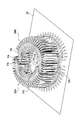
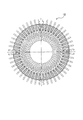
コイル11は、図3乃至図6に示され上記に説明する構成に形成されており、これを円環状に48個配置することでコイル籠12を形成する。図7に、半円環状コイル籠20同士を組み付ける様子を表す平面図を示す。図8に、半円環状コイル籠20同士を組み付ける様子を表す斜視図を示す。図9に、半円環状コイル籠20同士を重ねた様子を表す平面図を示す。図10に、半円環状コイル同士を重ねた様子を表す斜視図を示す。図11に、コイル籠12の平面図を示す。図12にコイル籠12の斜視図を示す。半円環状コイル籠20は、コイル籠12を形成する為に第1半円環状コイル籠20Aと第2半円環状コイル籠20Bの2つ用意される。第1半円環状コイル籠20A及び第2半円環状コイル籠20Bは、コイル11を24対組み合わせたもので、同様の形状である。コイル籠12として組み付けるには、第1半円環状コイル籠20Aと第2半円環状コイル籠20Bを図8及び図9に示すように向かい合わせに配置する。
この際、図7乃至図10に示すように、第1半円環状コイル籠20A及び第2半円環状コイル籠20Bの有する端子Mが形成する平面25上を、第1半円環状コイル籠20Aに対して第2半円環状コイル籠20Bを移動させて組み付ける。なお平面25は軸21A又は軸21Bに対して直行する面である。また、干渉を避けるために第1半円環状コイル籠20Aに対して第2半円環状コイル籠20Bを図7乃至図10に示すように、斜めにスライドさせて組み付けることで、コイル籠12を形成する。こうして形成されたコイル籠12をステータコア13に組み付け、ロータ40を挿入することでモータ100が形成されることになる。
ステータコア13は特に単体で図示して説明はしていないが、プレス加工でドーナツ状に打ち抜いた電磁鋼板を積層して形成されており、ステータコア13の内周側にティースが突出し、隣り合うティースの間にはスロット内導線部SA又はスロット内導線部SBが挿入されるスロットが用意されている。ティースの数は48本であり、スロットもティースと同数用意されている。このステータコア13にコイル籠12を軸方向から挿入することで、ステータ10が形成される。そして、ステータ10の一方のコイルエンド側であり、コイル籠12の下側同心円部Hが配置される側の反対側からロータ40を挿入することで、モータ100が形成される。なお、ロータ40に備えられるシャフト41は図示しないベアリングに回動可能に保持され、ベアリングが固定されるケーシングはステータコア13に固定される。
本実施形態のモータ100の製造方法は上記構成であるので、以下に説明する作用及び効果を奏する。まず、組み付け工程が簡略化することができる点が挙げられる。本実施形態のモータ100の製造方法は、コイル11の一端のコイルエンド部が、ステータコア13のスロット内導線部SA又はスロット内導線部SBに対してロータ40側に折り曲げられて形成され、コイル11を重ねて半円環状に配置し、第1半円環状コイル籠20Aと第2半円環状コイル籠20Bとを形成し、第1半円環状コイル籠20Aに対して第2半円環状コイル籠20Bを近接させ、第1半円環状コイル籠20Aと第2半円環状コイル籠20Bとで形成されたコイル籠12を、コイル11の一端のコイルエンド部がロータ40側に折り曲げられている側からステータコア13に挿入することで、モータ100を製造するものである。
コイル籠12を形成する為にコイル11を単純に重ねていくだけでは部分的に干渉してしまう。図13に、コイル11同士の軸方向の干渉を解説するための模式図を示す。図14に、コイル11同士の径方向の干渉を解説するための模式図を示す。便宜的に動かさずに保持している側のコイル11を、第1コイル11A、第1コイル11Aに対して近接させ、組み付ける側のコイル11を第2コイル11Bとして説明する。
第1コイル11Aに対して第2コイル11Bを、コイル籠12として組み付けられた時の軸の方向から近接する、すなわち軸方向に組み付けるとすると、図13に示す通り、第1コイル11Aの水平部FAと第2コイル11Bの傾斜部EBとが干渉してしまう。これは、図5に示されるように、傾斜部EBが水平部FAよりもコイル籠12の外周側(図5では上側)に配置される形状となっている為であり、軸方向に重ねる際には水平部FAと傾斜部EBはお互いに干渉し合う。
一方、第1コイル11Aと第2コイル11Bとをコイル籠12の径方向に重ねる図14の様な組み合わせ方を行うと、第1コイル11Aの水平部FAと第2コイル11Bの水平部FAとが干渉してしまう。したがって、コイル11同士が干渉しない為にはコイル籠12の周方向に組み付ける必要がある。図15に、コイル11同士を周方向に組み付ける様子を図に示す。第1コイル11Aに対して第2コイル11Bを横方向に、すなわちコイル籠12の周方向に組み付けることで、コイル11同士の干渉を抑えることが可能となる。
ただし、単純にコイル11をコイル籠12の周方向に組み付けていくと、42個までは順に組み付けることが可能だが、残り6つを組み付けることが出来ない問題が生じる。図16に、組み付け途中のコイル籠12の斜視図を示す。コイル11を42個組み付けた状況のコイル籠12が図16に示すものであり、コイル11の形状の特性上、第37スロット内導線部SA37乃至第42スロット内導線部SA42が、第1スロット内導線部SB1と第42スロット内導線部SB42との間に配置される。この状態で、コイル籠12の全周が埋め尽くされてしまうので、コイル11をこれ以上挿入することが出来ない。
そこで、図7乃至図10に示すように、第1半円環状コイル籠20Aと第2半円環状コイル籠20Bを形成し、第1半円環状コイル籠20Aと第2半円環状コイル籠20Bを対面させて組み付けることで、結果的にコイル11を周方向から組み付ける状態と同じ状態とし、48個のコイル11をコイル籠12に組み付けることが可能となる。
なお、図5に示すようにコイル11の形状は、傾斜部EA及び傾斜部EBがコイル籠12の内周方向(図5においては図面下方向)に向かって曲がった形状に形成されている。また、第1半円環状コイル籠20Aの1番目のコイル11の有するスロット内導線部SAと第2半円環状コイル籠20Bの24番目のコイル11の有するスロット内導線部SBとが干渉しないように、あるいは第1半円環状コイル籠20Aの24番目のコイル11の有するスロット内導線部SBと第2半円環状コイル籠20Bの1番目のコイル11が有するスロット内導線部SAとが干渉しないようにする必要がある。このため、組み付けの際には図7乃至図10に示されるように、第1半円環状コイル籠20Aに対して第2半円環状コイル籠20Bを斜め方向からアプローチさせる必要がある。
すなわち、図7に示すように、第1半円環状コイル籠20Aの軸21Aと交わる線であって、12番目のコイル11の下側同心円部Hの中心を通過する第1中心線21Aaと、24番目のコイル11の下側同心円部Hの中心を通過する第2中心線21Abと、第2半円環状コイル籠20Bの軸21Bと交わる線であって、12番目のコイル11の下側同心円部Hの中心を通過する第1中心線21Baと、24番目のコイル11の下側同心円部Hの中心を通過する第2中心線21Bbとが描かれるとする。この場合において、第1半円環状コイル籠20Aの第1中心線21Aaの上を、第2半円環状コイル籠20Bの第2中心線21Bbが重ならない位置から第2半円環状コイル籠20Bを近接させることとなる。
こうして、同芯巻きコイルであるコイル11を無理なくコイル籠12に組み付けることが可能となり、その結果、コイル11を用いたモータ100を形成可能であるので、コイル11を用いたモータ100の製造方法において、組み付け性を改善させることが可能である。
以上、本実施形態に則して発明を説明したが、この発明は前記実施形態に限定されるものではなく、発明の趣旨を逸脱することのない範囲で構成の一部を適宜変更することにより実施することもできる。
例えば、本実施形態で例示した材質は適宜置き換えることを妨げないし、コイル11の巻き数やステータコア13のスロットの数或いはコイル籠12に用いるコイル11の数なども設計仕様によって変更されることを妨げない。
10 ステータ
11 コイル
11A 第1コイル
11B 第2コイル
12 コイル籠
13 ステータコア
20 半円環状コイル
20A 第1半円環状コイル
20B 第2半円環状コイル
40 ロータ
41 シャフト
43 ロータコア
100 モータ
EA 傾斜部
EB 傾斜部
FA 水平部
FB 水平部
G 上側同心円部
H 下側同心円部
IA 折り曲げ部
IB 折り曲げ部
JA 折り曲げ部
JB 折り曲げ部
M 端子
N 端子
SA スロット内導線部
SB スロット内導線部
11 コイル
11A 第1コイル
11B 第2コイル
12 コイル籠
13 ステータコア
20 半円環状コイル
20A 第1半円環状コイル
20B 第2半円環状コイル
40 ロータ
41 シャフト
43 ロータコア
100 モータ
EA 傾斜部
EB 傾斜部
FA 水平部
FB 水平部
G 上側同心円部
H 下側同心円部
IA 折り曲げ部
IB 折り曲げ部
JA 折り曲げ部
JB 折り曲げ部
M 端子
N 端子
SA スロット内導線部
SB スロット内導線部
Claims (1)
- 平角導体を用いた分布巻きコイルとステータコアとを備えるステータと、中心軸を備えるロータとを有するモータを、前記分布巻きコイルを組み合わせてコイル籠を形成し、前記コイル籠をステータコアに軸方向から挿入することでモータを製造するモータ製造方法において、
前記コイルの一端のコイルエンド部が、前記ステータコアのスロット内導線部に対して前記ロータ側に折り曲げられて形成され、
前記コイルを重ねて半円環状に配置し、第1半円環状コイル籠と第2半円環状コイル籠とを形成し、
前記第1半円環状コイル籠に対して前記第2半円環状コイル籠を軸に直行する面上を移動させるように近接させ、
前記第1半円環状コイル籠と前記第2半円環状コイル籠とで形成された前記コイル籠を、前記コイルの一端のコイルエンド部がロータ側に折り曲げられている側から前記ステータコアに挿入することで、前記モータを製造することを特徴とするモータ製造方法。
Priority Applications (2)
| Application Number | Priority Date | Filing Date | Title |
|---|---|---|---|
| PCT/JP2011/055385 WO2012120643A1 (ja) | 2011-03-08 | 2011-03-08 | モータ製造方法 |
| JP2011536683A JP5278555B2 (ja) | 2011-03-08 | 2011-03-08 | モータ製造方法 |
Applications Claiming Priority (1)
| Application Number | Priority Date | Filing Date | Title |
|---|---|---|---|
| PCT/JP2011/055385 WO2012120643A1 (ja) | 2011-03-08 | 2011-03-08 | モータ製造方法 |
Publications (1)
| Publication Number | Publication Date |
|---|---|
| WO2012120643A1 true WO2012120643A1 (ja) | 2012-09-13 |
Family
ID=46797646
Family Applications (1)
| Application Number | Title | Priority Date | Filing Date |
|---|---|---|---|
| PCT/JP2011/055385 Ceased WO2012120643A1 (ja) | 2011-03-08 | 2011-03-08 | モータ製造方法 |
Country Status (2)
| Country | Link |
|---|---|
| JP (1) | JP5278555B2 (ja) |
| WO (1) | WO2012120643A1 (ja) |
Cited By (6)
| Publication number | Priority date | Publication date | Assignee | Title |
|---|---|---|---|---|
| JP2018164402A (ja) * | 2018-07-26 | 2018-10-18 | 本田技研工業株式会社 | 電気導体の整列方法及びその装置 |
| WO2020022338A1 (ja) * | 2018-07-23 | 2020-01-30 | 株式会社小田原エンジニアリング | コイルの端子接続方法、ツイスト治具及び回転電機のステータ |
| US10923993B2 (en) | 2017-02-14 | 2021-02-16 | Honda Motor Co., Ltd. | Alignment method and apparatus for electric conductors |
| JP2022137412A (ja) * | 2021-03-09 | 2022-09-22 | 三菱電機株式会社 | ステーター、ステーターの製造方法、交流回転電機の製造方法、誘導電動機および送風機 |
| JP2023145164A (ja) * | 2022-03-28 | 2023-10-11 | 株式会社アイシン | ステータ |
| WO2024023533A1 (en) * | 2022-07-28 | 2024-02-01 | Saietta Group PLC | Method and apparatus for forming a coil pack |
Families Citing this family (2)
| Publication number | Priority date | Publication date | Assignee | Title |
|---|---|---|---|---|
| DE102021126719A1 (de) | 2021-10-14 | 2023-04-20 | Gehring Technologies Gmbh + Co. Kg | Vorrichtung, Maschine und Verfahren zur Erzeugung einer Endkonfiguration von Leiterstücken |
| DE102022114610B4 (de) * | 2022-06-10 | 2025-11-27 | Schaeffler Technologies AG & Co. KG | Stator, elektrische Maschine und Verfahren zur Herstellung eines Stators |
Citations (3)
| Publication number | Priority date | Publication date | Assignee | Title |
|---|---|---|---|---|
| JPS5149042B1 (ja) * | 1969-01-16 | 1976-12-24 | ||
| JPS5619363A (en) * | 1979-07-19 | 1981-02-24 | Matsushita Electric Ind Co Ltd | Inserting method for coil winding and inserting device for coil winding |
| JP2010226862A (ja) * | 2009-03-23 | 2010-10-07 | Aisin Aw Co Ltd | ステータの製造装置 |
Family Cites Families (3)
| Publication number | Priority date | Publication date | Assignee | Title |
|---|---|---|---|---|
| JP5055937B2 (ja) * | 2006-10-12 | 2012-10-24 | 株式会社明電舎 | 回転電機の巻線絶縁構造 |
| JP5363403B2 (ja) * | 2010-04-19 | 2013-12-11 | トヨタ自動車株式会社 | モータ |
| JP5292360B2 (ja) * | 2010-06-10 | 2013-09-18 | トヨタ自動車株式会社 | モータ |
-
2011
- 2011-03-08 JP JP2011536683A patent/JP5278555B2/ja not_active Expired - Fee Related
- 2011-03-08 WO PCT/JP2011/055385 patent/WO2012120643A1/ja not_active Ceased
Patent Citations (3)
| Publication number | Priority date | Publication date | Assignee | Title |
|---|---|---|---|---|
| JPS5149042B1 (ja) * | 1969-01-16 | 1976-12-24 | ||
| JPS5619363A (en) * | 1979-07-19 | 1981-02-24 | Matsushita Electric Ind Co Ltd | Inserting method for coil winding and inserting device for coil winding |
| JP2010226862A (ja) * | 2009-03-23 | 2010-10-07 | Aisin Aw Co Ltd | ステータの製造装置 |
Cited By (8)
| Publication number | Priority date | Publication date | Assignee | Title |
|---|---|---|---|---|
| US10923993B2 (en) | 2017-02-14 | 2021-02-16 | Honda Motor Co., Ltd. | Alignment method and apparatus for electric conductors |
| WO2020022338A1 (ja) * | 2018-07-23 | 2020-01-30 | 株式会社小田原エンジニアリング | コイルの端子接続方法、ツイスト治具及び回転電機のステータ |
| JP6685572B1 (ja) * | 2018-07-23 | 2020-04-22 | 株式会社小田原エンジニアリング | コイルの端子接続方法、ツイスト治具及び回転電機のステータ |
| JP2018164402A (ja) * | 2018-07-26 | 2018-10-18 | 本田技研工業株式会社 | 電気導体の整列方法及びその装置 |
| JP2022137412A (ja) * | 2021-03-09 | 2022-09-22 | 三菱電機株式会社 | ステーター、ステーターの製造方法、交流回転電機の製造方法、誘導電動機および送風機 |
| JP7630308B2 (ja) | 2021-03-09 | 2025-02-17 | 三菱電機株式会社 | ステーター、ステーターの製造方法、交流回転電機の製造方法、誘導電動機および送風機 |
| JP2023145164A (ja) * | 2022-03-28 | 2023-10-11 | 株式会社アイシン | ステータ |
| WO2024023533A1 (en) * | 2022-07-28 | 2024-02-01 | Saietta Group PLC | Method and apparatus for forming a coil pack |
Also Published As
| Publication number | Publication date |
|---|---|
| JPWO2012120643A1 (ja) | 2014-07-07 |
| JP5278555B2 (ja) | 2013-09-04 |
Similar Documents
| Publication | Publication Date | Title |
|---|---|---|
| JP5278555B2 (ja) | モータ製造方法 | |
| KR101326477B1 (ko) | 모터 및 모터 제조 방법 | |
| JP5292360B2 (ja) | モータ | |
| JP5278546B2 (ja) | ステータ | |
| JP5167939B2 (ja) | 回転電機のコイル組立体製造方法 | |
| JP5560176B2 (ja) | モータ及びモータ製造方法 | |
| JP5278553B2 (ja) | モータ製造方法 | |
| JP5370491B2 (ja) | ステータ及びステータ製造方法 | |
| JP6261809B2 (ja) | 固定子および回転電機 | |
| US20170141632A1 (en) | Stator manufacturing method and stator | |
| CN102812620A (zh) | 旋转电机的定子、定子的制造方法、以及定子的线圈的制造方法 | |
| US9009948B2 (en) | Method of manufacturing stator coil for electric rotating machine | |
| WO2015162643A1 (ja) | 回転電機の固定子及びこの固定子を用いた回転電機 | |
| US20180212498A1 (en) | Coil unit arrangement device | |
| JP2014050180A (ja) | 回転電機のステータコイル構造 | |
| JP4443286B2 (ja) | 回転電動機の固定子、回転電動機のコイル装着方法、コイル巻線機 | |
| JP2013251996A (ja) | コイルの製造方法 | |
| JP2012235544A (ja) | モータ製造方法、モータ | |
| JP2019205230A (ja) | 回転電機の固定子の製造方法 | |
| JP2019176589A (ja) | 巻きコイル、回転電機用のコイル、回転電機、巻きコイルの製造方法及び装置 | |
| JP2012235573A (ja) | モータ、及びモータ製造方法 | |
| JP2013021858A (ja) | モータ製造方法 | |
| WO2005064768A1 (ja) | スロットレスモータ及びその製造方法 |
Legal Events
| Date | Code | Title | Description |
|---|---|---|---|
| ENP | Entry into the national phase |
Ref document number: 2011536683 Country of ref document: JP Kind code of ref document: A |
|
| 121 | Ep: the epo has been informed by wipo that ep was designated in this application |
Ref document number: 11860338 Country of ref document: EP Kind code of ref document: A1 |
|
| NENP | Non-entry into the national phase |
Ref country code: DE |
|
| 122 | Ep: pct application non-entry in european phase |
Ref document number: 11860338 Country of ref document: EP Kind code of ref document: A1 |