WO2012120649A1 - 電気自動車用駆動装置 - Google Patents
電気自動車用駆動装置 Download PDFInfo
- Publication number
- WO2012120649A1 WO2012120649A1 PCT/JP2011/055397 JP2011055397W WO2012120649A1 WO 2012120649 A1 WO2012120649 A1 WO 2012120649A1 JP 2011055397 W JP2011055397 W JP 2011055397W WO 2012120649 A1 WO2012120649 A1 WO 2012120649A1
- Authority
- WO
- WIPO (PCT)
- Prior art keywords
- housing
- electric motor
- reduction unit
- drive device
- speed reduction
- Prior art date
- Legal status (The legal status is an assumption and is not a legal conclusion. Google has not performed a legal analysis and makes no representation as to the accuracy of the status listed.)
- Ceased
Links
Images


Classifications
-
- H—ELECTRICITY
- H02—GENERATION; CONVERSION OR DISTRIBUTION OF ELECTRIC POWER
- H02K—DYNAMO-ELECTRIC MACHINES
- H02K11/00—Structural association of dynamo-electric machines with electric components or with devices for shielding, monitoring or protection
- H02K11/0094—Structural association with other electrical or electronic devices
-
- H—ELECTRICITY
- H02—GENERATION; CONVERSION OR DISTRIBUTION OF ELECTRIC POWER
- H02K—DYNAMO-ELECTRIC MACHINES
- H02K11/00—Structural association of dynamo-electric machines with electric components or with devices for shielding, monitoring or protection
- H02K11/20—Structural association of dynamo-electric machines with electric components or with devices for shielding, monitoring or protection for measuring, monitoring, testing, protecting or switching
- H02K11/21—Devices for sensing speed or position, or actuated thereby
- H02K11/225—Detecting coils
-
- H—ELECTRICITY
- H02—GENERATION; CONVERSION OR DISTRIBUTION OF ELECTRIC POWER
- H02K—DYNAMO-ELECTRIC MACHINES
- H02K5/00—Casings; Enclosures; Supports
- H02K5/04—Casings or enclosures characterised by the shape, form or construction thereof
- H02K5/16—Means for supporting bearings, e.g. insulating supports or means for fitting bearings in the bearing-shields
- H02K5/173—Means for supporting bearings, e.g. insulating supports or means for fitting bearings in the bearing-shields using bearings with rolling contact, e.g. ball bearings
- H02K5/1732—Means for supporting bearings, e.g. insulating supports or means for fitting bearings in the bearing-shields using bearings with rolling contact, e.g. ball bearings radially supporting the rotary shaft at both ends of the rotor
-
- H—ELECTRICITY
- H02—GENERATION; CONVERSION OR DISTRIBUTION OF ELECTRIC POWER
- H02K—DYNAMO-ELECTRIC MACHINES
- H02K5/00—Casings; Enclosures; Supports
- H02K5/04—Casings or enclosures characterised by the shape, form or construction thereof
- H02K5/22—Auxiliary parts of casings not covered by groups H02K5/06-H02K5/20, e.g. shaped to form connection boxes or terminal boxes
- H02K5/225—Terminal boxes or connection arrangements
-
- H—ELECTRICITY
- H02—GENERATION; CONVERSION OR DISTRIBUTION OF ELECTRIC POWER
- H02K—DYNAMO-ELECTRIC MACHINES
- H02K7/00—Arrangements for handling mechanical energy structurally associated with dynamo-electric machines, e.g. structural association with mechanical driving motors or auxiliary dynamo-electric machines
- H02K7/08—Structural association with bearings
- H02K7/083—Structural association with bearings radially supporting the rotary shaft at both ends of the rotor
-
- H—ELECTRICITY
- H02—GENERATION; CONVERSION OR DISTRIBUTION OF ELECTRIC POWER
- H02K—DYNAMO-ELECTRIC MACHINES
- H02K7/00—Arrangements for handling mechanical energy structurally associated with dynamo-electric machines, e.g. structural association with mechanical driving motors or auxiliary dynamo-electric machines
- H02K7/10—Structural association with clutches, brakes, gears, pulleys or mechanical starters
- H02K7/116—Structural association with clutches, brakes, gears, pulleys or mechanical starters with gears
-
- H—ELECTRICITY
- H02—GENERATION; CONVERSION OR DISTRIBUTION OF ELECTRIC POWER
- H02K—DYNAMO-ELECTRIC MACHINES
- H02K5/00—Casings; Enclosures; Supports
- H02K5/04—Casings or enclosures characterised by the shape, form or construction thereof
- H02K5/18—Casings or enclosures characterised by the shape, form or construction thereof with ribs or fins for improving heat transfer
-
- Y—GENERAL TAGGING OF NEW TECHNOLOGICAL DEVELOPMENTS; GENERAL TAGGING OF CROSS-SECTIONAL TECHNOLOGIES SPANNING OVER SEVERAL SECTIONS OF THE IPC; TECHNICAL SUBJECTS COVERED BY FORMER USPC CROSS-REFERENCE ART COLLECTIONS [XRACs] AND DIGESTS
- Y02—TECHNOLOGIES OR APPLICATIONS FOR MITIGATION OR ADAPTATION AGAINST CLIMATE CHANGE
- Y02T—CLIMATE CHANGE MITIGATION TECHNOLOGIES RELATED TO TRANSPORTATION
- Y02T10/00—Road transport of goods or passengers
- Y02T10/60—Other road transportation technologies with climate change mitigation effect
- Y02T10/64—Electric machine technologies in electromobility
Definitions
- the present invention relates to an electric vehicle drive device using an electric motor as a drive source, and more particularly to an in-wheel motor drive device for an electric vehicle.
- a conventionally known in-wheel motor drive device for an electric vehicle includes an electric motor, a reduction unit that receives the motor output, and a hub unit that is rotated by the reduction output of the reduction unit ( Patent Document 1).
- an electric motor is arranged on the radially outer side of the reduction unit, and the reduction unit is a planetary gear type arranged in two stages in the axial direction.
- the reason why the reduction units are arranged in two stages is to increase the reduction ratio.
- the general configuration of a planetary gear type reduction unit is that a sun gear is coaxially provided on an input shaft, and a ring gear is fixed coaxially around the input shaft.
- a plurality of pinion gears are interposed between the sun gear and the ring gear, and pinion pins that support the pinion gears are connected to a common carrier.
- the carrier is integrated with the output member.
- the deceleration unit revolves while the pinion gear rotates as the input shaft rotates.
- the rotational speed of the revolution is decelerated from the rotational speed of the input shaft, and the decelerated rotation is transmitted to the output member through the carrier.
- the reduction ratio in this case is Zs / (Zs + Zr).
- Zs is the number of teeth of the sun gear
- Zr is the number of teeth of the ring gear.
- the input shaft of the deceleration unit is supported by two bearings arranged in the axial direction, that is, an inboard side bearing and an outboard side bearing.
- the inboard side bearing is attached to the housing of the reduction unit, and the outboard side bearing is attached to the output member of the reduction unit.
- the housing is supported by the vehicle body via the suspension, and the output member is coupled and integrated with the inner member of the hub unit to drive the wheel.
- the load acting on the input shaft of the speed reduction unit is supported by the housing on the inboard side via the inboard side bearing, and on the outboard side via the outboard side bearing. Supported by the output member of the deceleration unit.
- Patent Document 1 as a power supply means for an electric motor, a power connector connected to a power cable through a seal ring is inserted into a mounting hole provided in a rear cover of the housing, and a lead wire on the electric motor side is connected to the connector. It is designed to be connected to and energized. (Patent Document 1).
- the structure of the housing is complicated, and a power connector that is an independent component is required, which increases the number of components and hinders the compactness of the apparatus.
- the power connector may fall off due to vibration or impact transmitted from the wheels.
- the present invention eliminates the need for a power connector as an independent component as a power supply means for the electric motor, thereby reducing costs and reducing the size of the electric motor, and is mechanically affected by vibrations and the like.
- Another object of the present invention is to provide a drive device for an electric vehicle provided with a stable power supply means.
- the present invention provides an electric motor, a reduction unit including an input shaft driven by an output of the electric motor, a hub unit rotated by an output member of the reduction unit, and the electric motor And a housing housing the speed reduction unit, the rear end of the housing portion of the electric motor and the speed reduction unit of the housing is opened, the open portion is closed by a rear cover, and the power supply means for the electric motor includes the power supply means
- the power supply means includes a storage recess provided in a rear end surface of the housing, a power terminal provided in the storage recess, a storage recess, and the housing interior.
- It consists of a power supply terminal box consisting of a communication hole leading to , Leads of the electric motor is connected to the power supply terminal through the communication holes, in which through holes of the connection terminals of the power cable to the power supply terminal box has a configuration provided.
- the power terminal box is provided using the storage recess provided in the housing, it is possible to energize the electric motor from the power cable without using an independent connector part. Compared with what is provided in the rear cover of a housing, the structure of the rear cover is simplified.
- the housing is provided with a partition wall for partitioning the storage portion of the electric motor and the storage portion of the reduction unit, and an axial gap type or radial gap type rotation sensor is provided between the partition wall and the rotor support member of the electric motor.
- the lead wire terminal of the rotation sensor can be configured to be provided in a connector insertion portion provided in the casing.
- the signal detected by the rotation sensor is input to the control device via a signal cable connected at the connector insertion portion.
- This configuration simplifies the structure of the rear cover compared to those who provide a rotation sensor between the center hole of the rear cover and the input shaft.
- an oil seal member may be interposed between the output member and the outer member of the hub unit.
- the output member has flanges arranged on both sides in the axial direction of the reduction rotation member such as a pinion gear, and both end portions of the support pins of the reduction rotation member are fixed to the flanges. It is possible to adopt a configuration in which the flanges are coupled and integrated, and the respective bearings are interposed between the inner diameter surface of each flange and the input shaft.
- the “deceleration rotating member” and the “support pin” correspond to a pinion gear and a pinion pin, respectively.
- the above-described speed reduction unit can be interposed between the flanges because the flanges on both sides are coupled and integrated by the support pins.
- ⁇ A configuration in which the flanges are coupled by a bridge can be adopted, and the flanges can be firmly coupled and integrated by the bridge.
- the support rigidity of the support pins such as pinion pins whose both ends are coupled to the both flanges is improved. Further, by providing the bridges at a plurality of positions in the circumferentially equidistant position, the output member can be smoothly rotated, and the rotational accuracy of the input shaft and the rotor of the electric motor fitted and fixed thereto is improved.
- the power terminal box is configured using the storage recess provided in the housing, a connector as an independent component is not required, and the number of components can be reduced. Further, the configuration of the rear cover of the housing can be simplified.
- the rear cover is further simplified, and a thin metal plate or resin is further developed. It can be composed of a plate or the like.
- FIG. 1 is a cross-sectional view of Embodiment 1.
- FIG. FIG. 3 is a partially enlarged cross-sectional view of the first embodiment.
- FIG. 3 is an enlarged sectional view taken along line X1-X1 of FIG. It is a perspective view of the spacer shown in FIG.
- FIG. 2 is a cross-sectional view taken along line X2-X2 of FIG. It is sectional drawing of the modification of the deceleration unit part. It is sectional drawing of the X3-X3 line
- FIG. 7 is a cross-sectional view showing a part of the second embodiment.
- FIG. 8 is a cross-sectional view of the third embodiment.
- FIG. 9 is a side view of the third embodiment.
- FIG. 10 is a partial cross-sectional view of a modification of the third embodiment.
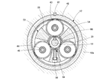
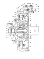
- the electric vehicle drive device includes an electric motor 11, a speed reduction unit 12 driven by the output of the electric motor 11, and an output member coaxial with the input shaft 13 of the speed reduction unit 12.
- the main unit is a hub unit 15 that is rotated by the motor 14 and a housing 16 that houses the electric motor 11 and the speed reduction unit 12.
- the housing 16 has a cylindrical portion 17 and a front end 18 in the radial direction provided at the front end thereof (the end on the outboard side, the left end in the figure).
- the front end 18 is opened at the center, the rear end of the outer member 21 of the hub unit 15 is fitted into the open portion 19, and the flange 22 is fixed to the front end 18 by a bolt 23.
- a partition wall base 18a having a larger diameter than that of the opening hole 19 is provided on the inner side of the front end 18 of the housing 16.
- a dish-shaped partition member 20 is fixed to the partition base 18a by bolts 20a.
- a center hole 25 is provided at the center of the partition member 20. The center hole 25 faces the outer diameter surface of the input shaft 13 with a radial gap.
- a partition wall 24 is formed by the partition base 18a and the partition member 20 connected and fixed thereto. The partition wall 24 has a function of partitioning the housing 16 into a housing space for the electric motor 11 on the outer diameter side and a housing space for the reduction unit 12 on the inner diameter side.
- Suspension connecting portions 27 protruding in the axial direction are provided at two positions symmetrical with respect to the rear end edge of the cylindrical portion 17 of the housing 16.
- the hub unit 15 is connected to the suspension via the knuckle of the vehicle body.
- the suspension unit 27 which is a part of the housing 16 is connected to the suspension on the vehicle body side. Can be directly linked.
- the housing 16 functions as a knuckle, it can be said that the housing 16 has a structure in which the knuckle is integrated. In this case, when the outer member 21 of the hub unit 15 needs to be replaced, it is not necessary to remove the housing 16 from the suspension, and the replacement can be performed by simply removing the bolt 23.
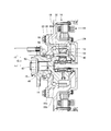
- the electric motor 11 is a brushless DC motor of a radial gap type, and is arranged with a stator 28 fixed to the inner surface of the cylindrical portion 17 of the housing 16 and a radial gap on the inner surface of the stator 28. And the rotor 29.
- the rotor 29 is fitted and fixed to the input shaft 13 by a rotor support member 31.
- the rotor support member 31 includes a support member cylindrical portion 31a (see FIG. 2) fitted to the inner diameter portion of the rotor 29, and a support member disk portion 31b extending rearward along the partition wall 24 and bent in the inner diameter direction. Composed.
- a boss portion 31 c is provided on the inner diameter portion of the support member disk portion 31 b, the boss portion 31 c is fitted to the input shaft 13, and is fixed to the input shaft 13 by the key stopper 35.
- the boss portion 31c is inserted on the inner diameter side of the center hole 25 of the partition wall 24, and an oil seal member 36 is interposed between the center hole 25 and the boss portion 31c (see FIG. 2).
- the partition wall 24 and the oil seal member 36 By the partition wall 24 and the oil seal member 36, the storage portion of the electric motor 11 and the storage portion of the speed reduction unit 12 are partitioned and oil-sealed.
- the lubricating oil on the speed reduction unit 12 side is prevented from moving to the electric motor 11 side, the electric motor 11 side is kept dry, and the problem that the lubricating oil hinders the rotation of the rotor 29 is eliminated.
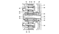
- the reduction gear unit 12 is of a planetary gear type. As shown in FIG. 2, the input shaft 13, the output member 14, a sun gear 39 attached to the outer diameter surface of the input shaft by a key stopper 38, and the sun gear 39.
- the ring gear 42 is disposed along the inner surface of the boundary portion between the partition wall base 18a and the partition wall member 20 and is attached by the key stopper 41.
- the ring gear 42 and the sun gear 39 are equally spaced in the circumferential direction.
- pinion gears 43 provided at three locations. The pinion gear 43 is supported by a pinion pin 45 through a needle roller bearing 44.
- the output member 14 has a coupling shaft portion 47 at the end portion on the outboard side.
- the coupling shaft portion 47 is splined to the inner member 46 of the hub unit 15 and fixed by the nut 50.
- a bearing support portion 49 On the inner end side of the coupling shaft portion 47, a bearing support portion 49 that is formed to have a larger diameter than that is provided.
- a pair of flanges 52 and 53 facing in the axial direction are provided on the inboard side of the output member 14 with an interval slightly larger than the width of the pinion gear 43 in the axial direction.
- Bridges 54 for connecting the flanges 52 and 53 to each other in the axial direction are provided at three circumferentially equidistant positions.
- the flanges 52 and 53 have a carrier function in the planetary gear type reduction unit 12.
- the output member 14 is smoothly rotated, and as a result, the rotational accuracy of the rotor 29 of the electric motor 11 is improved through the output member 14 and the input shaft 13.
- a shaft hole 51 is provided at the center of the end surface of the flange 53 on the inboard side at the center coaxial with the coupling shaft portion 47.
- the shaft hole 51 has a length that reaches the bearing support portion 49.
- Three pinion gear storage portions 55 partitioned in the circumferential direction are provided by a pair of flanges 52 and 53 opposed in the axial direction and three bridges 54 in the circumferential direction (see FIG. 3).
- the pinion gear 43 is housed in each pinion gear housing portion 55, and both end portions of the pinion pin 45 are inserted into the flanges 52 and 53 and fixed by set screws 56. It can be said that both the flanges 52 and 53 are coupled and integrated not only by the bridge 54 but also by the pinion pin 45.
- a thrust plate 57 is interposed between both side surfaces of each pinion gear 43 and each flange 52, 53 in order to ensure smooth rotation of the pinion gear 43.
- a pair of rolling bearings 58 and 59 for supporting the input shaft 13 are provided on both sides of the sun gear 39 between the inner diameter surfaces of the flanges 52 and 53 and the outer diameter surface of the input shaft 13 facing the inner diameter surfaces. Provided. By adopting this configuration, the rolling bearings 58 and 59 are both supported by the same output member 14.
- the positional relationship in the axial direction of the rolling bearings 58 and 59 and the fitting portion between the support member disk portion 31 b and the input shaft 13 is the same for each rolling bearing 58 and 59.
- the support structure for the input shaft 13 disposed on the board side is a so-called cantilever support structure.
- the bearing on the outboard side is disposed on the outboard side from the fitting portion between the support member disk portion and the input shaft, whereas the bearing on the inboard side is arranged. Since the bearing is attached to the housing, it is on the inboard side from the fitting portion. Therefore, the support structure of the input shaft is a so-called both-end support structure.
- the cantilevered support structure has a feature that the structure is simplified as compared with the both-end supported structure.
- the above-mentioned rolling bearing 58 on the outboard side is engaged with the stepped portion 61 provided on the input shaft 13 on the inner ring and the stepped portion 62 provided on the inner diameter surface of the shaft hole 51 on the outer ring.
- the inboard side rolling bearing 59 has its inner ring engaged with the boss 31c and the key stopper 35 of the rotor support member 31, and the outer ring engaged with the retaining ring 63.
- a sun gear 39 is interposed between the inner rings of the rolling bearings 58 and 59, and a spacer 64 is interposed between the outer rings.
- the spacer 64 prevents both rolling bearings 58, 59 from being displaced in a direction approaching each other.
- the spacer 64 is formed in a cylindrical state, and is provided with window holes 65 that match the shape of the pinion gear storage portion 55 at three locations in the circumferential direction.
- the 65 closed portions 66 are formed in a shape that follows the shape of the bottom surface of the bridge 54.
- the spacer 64 is interposed between the rolling bearings 58 and 59 on the inner diameter surface of the shaft hole 51 in a posture in which each window hole 65 matches the pinion gear housing portion 55 (see FIG. 3).
- the screw 67 is screwed into the positioning hole 60 (see FIG. 4) for positioning.
- the spacer 64 can control the bearing preload applied to both the rolling bearings 58 and 59 by appropriately setting the length in the axial direction, and has a simple fixed position preload structure.
- the deceleration unit 12 When viewed in the radial direction, the deceleration unit 12 is disposed in the radial direction accommodated on the inner diameter side of the electric motor 11 with the partition wall 24 interposed therebetween, so that the axial direction can be made compact as compared with the axial direction.
- the partition wall 24 will be described in more detail.
- the partition wall cylindrical portion 24b is interposed between the electric motor 11 arranged in the radial direction and the speed reduction unit 12, and the partition disk portion 24a is connected to the speed reduction unit 12.
- the support member disk portion 31b The peripheral edge of the center hole 25 faces the outer diameter surface of the boss 31c of the rotor support member 31 with a predetermined interval.
- the ring gear 42 of the speed reduction unit 12 is fixed to the inner diameter surface of the partition base 18a by the key stopper 41.
- An oil seal member 36 is interposed between the peripheral edge portion of the center hole 25 and the boss portion 31c. Due to the presence of the oil seal member 36 and the partition wall 24, the storage space for the electric motor 11 in the casing 16 and the storage space for the speed reduction unit 12 are partitioned. As a result, the lubricating oil on the speed reduction unit 12 side is prevented from moving to the electric motor 11 side, and the electric motor 11 side is kept dry, thereby preventing the lubricating oil from obstructing the rotation of the rotor 29.
- both the flanges 52 and 53 of the output member 14 are coupled and integrated by both the bridge 53 and the pinion pin 45.
- FIGS. 14 can be configured separately and combined and integrated by a pinion pin 45.
- the oil supply port 68 and the oil discharge port 69 for lubricating the inside of the speed reduction unit 12 are provided at the front end of the housing 16, respectively.
- the lubricating oil is sealed on the electric motor 11 side by the oil seal member 36, and the hub unit 15 side is interposed between the bearing support portion 49 of the output member 14 and the outer member 21 and is sealed by the oil seal member 70. Sealed.
- the oil supply port 68 and the oil discharge port 69 are each closed by a closing screw 72.
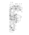
- the electric motor 11 and the speed reduction unit 12 are within the range of the axial length of the cylindrical portion 17 of the housing 16 except for the rear end portion (inboard side end portion) of the input shaft 13. Therefore, the rear cover 73 is fitted to the rear end portion of the cylindrical portion 17 via the seal member 60.
- a heat dissipation fin 74 is provided on the outer surface of the rear cover 73 so as to dissipate heat of the electric motor 11 to the outside.
- a rotation sensor 75 is provided between the center hole of the rear cover 73 and the input shaft 13 passing through the center hole, and the portion is closed by the sensor cover 77.
- the illustrated rotation sensor 75 is a resolver, and its sensor stator 75 a is fixed to the center hole of the rear cover 73, and the sensor rotor 75 b is attached to the input shaft 13.
- the lead wire 79 of the sensor stator 75 a is connected to a connector insertion part 78 provided outside the sensor cover 77.
- a Hall element or the like can be used in addition to the resolver.
- a connector (not shown) of a signal line cable is inserted into the connector insertion portion 78.
- the rotation angle of the input shaft 13 detected by the rotation sensor 75 is input to a control circuit (not shown) via the signal line cable and used for rotation control of the electric motor 11.
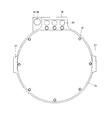
- a power supply terminal box 76 for supplying power to the stator 28 of the electric motor 11 is provided at a position eccentric to the outer peripheral edge of the rear cover 73 and at a 90-degree position different from that of the suspension connecting portion 27 ( (See FIG. 5).
- the power terminal box 76 is formed in a cylindrical shape penetrating the rear cover 73, and a work hole 80 is provided in the outer peripheral portion.
- the work hole 80 is normally closed by a lid 81.
- a power supply terminal 82 is provided at a position facing the work hole 80.
- a lead wire 83 connected to the winding of the stator 28 is connected to the power terminal 82, and a connection terminal of the power cable 84 is connected to the same power terminal 82. These are fixed by a tightening screw 85.
- a cable hole 84a is provided at the rear end of the power terminal box 76, and the power cable 84 is inserted through the cable hole 84a.
- the hub unit 15 includes the inner member 46 in which the hub 86 is integrated, a pair of inner rings 87 fitted to the outer diameter surface of the inner member 46, and the flange 22. , An outer ring 88 fitted to the inner diameter surface of the outer member 21 and having a double-row track, and a double-row ball 89 to be interposed between the inner ring 87 and the outer ring 88. Is done.
- the wheels are attached to the hub 86 by hub bolts 90.
- the connecting shaft portion 47 of the output member 14 is splined to the inner diameter surface of the inner member 46, and the distal end portion of the connecting shaft portion 47 protruding outward from the inner member 46 is fixed by the nut 50 as described above.
- fixing means such as press-cut joining, diameter expansion caulking, or rocking caulking can be employed.
- the hub unit 15 has a so-called first generation format, but a second generation or third generation format can be used.
- the electric vehicle drive device of Embodiment 1 is configured as described above, and the operation thereof will be described next.
- the input shaft 13 is rotated integrally with the rotation of the rotor 29, and the motor output is input to the speed reduction unit 12.
- the reduction unit 12 revolves while the pinion gear 43 rotates.
- the output member 14 is rotated at the deceleration output indicated by the reduction ratio.
- the inner member 46 of the hub unit 15 is rotated integrally with the connecting shaft portion 47 of the output member 14, and the wheel attached to the hub 86 is driven.
- the input shaft 13 is rotated on both sides of the pinion gear 43 by being supported by a rolling bearing 58 on the outboard side and a rolling bearing 59 on the inboard side, respectively.
- These rolling bearings 58 and 59 are attached to the flanges 52 and 53 integrated with the output member 14 (in the case of FIGS. 6A and 6B, the flanges 52 and 53 integrated with the pinion pin 45). Therefore, the radial vibration and impact transmitted from the wheel to the output member 14 via the hub unit 15 are simultaneously applied to both rolling bearings 58 and 59 in the same manner.
- any rolling bearings 58 and 59 can be prevented from applying an unbalanced load, so that the rotational accuracy and durability can be improved, and the noise of the rotating sound can be suppressed.
- the rolling bearings 58 and 59 are arranged on the outboard side of the fitting portion between the support member 31 of the rotor 29 and the input shaft 13, that is, the keying portion 35, and compared to the conventional case arranged on both sides thereof.
- the support structure is simple and easy to assemble.
- the lubricating oil in the speed reduction unit 12 is sealed to the electric motor 11 side by the oil seal member 36 and to the hub unit 15 side by the oil seal member 70, the lubricating oil is supplied to the electric motor 11 side and the hub unit side. Leakage is prevented. As a result, the rotation of the rotor 29 is not hindered on the electric motor 11 side, and the lubricating oil is prevented from leaking outside through the hub unit 15 on the hub unit 15 side.
- the heat generated as the electric motor 11 is driven is effectively dissipated by the fins 74 of the rear cover 73.
- the second embodiment shown in FIG. 7 is different from the first embodiment in the configuration of the hub unit 15. That is, the flange 22 of the outer ring member 21 of the hub unit 15 in this case is formed with a larger diameter than the flange 22 (see FIG. 1) of the first embodiment.
- a flange cylindrical portion 32 protruding in the axial direction is provided on the inner surface of the large-diameter flange 22.
- the flange cylindrical portion 32 extends on the outer diameter surface of the flange 53 on the outboard side of the output member 14.
- the flange cylindrical portion 32 is fitted to the inner diameter surface of the open hole 19 in the front end portion 18 of the housing 16.
- the partition wall 24 integral with the front end portion 18 in the second embodiment. For this reason, in the case of this Embodiment 2, the partition member 20 (refer FIG. 1) of another member is not used.
- the ball of the hub bearing 89a on the outboard side is interposed between the raceway groove formed on the outer diameter surface of the inner member 46 and the raceway groove formed on the inner diameter surface of the outer member 21.
- the balls of the hub bearing 89b on the inboard side are interposed between the raceway surface formed on the outer diameter surface of the flange 52 and the raceway groove formed on the inner diameter surface of the flange cylindrical portion 32.
- the bearing rigidity of the hub unit 15 is improved.
- the hub unit 15 in this case can be said to be a so-called third generation modified form.
- the balls of the hub bearings 89a and 89b are configured to directly contact the raceway grooves.
- bearings provided with raceway grooves in the inner ring and the outer ring are used, and these race rings are fitted to the facing members. Configuration can be taken.
- the configuration of the hub unit 15, the rotation sensor 75, the power supply terminal box 76 and the connector insertion portion 78 is different from that of the first embodiment.
- the flange 22 of the outer member 21 is formed with a larger diameter than in the case of the first embodiment. For this reason, it is not necessary to employ the auxiliary casing 16b as in the first embodiment, and the single casing 16 having the same structure as the main casing 16a is used.
- the large-diameter flange 22 is fixed to the casing 16 by bolts 23.
- the ball 89a on the outboard side constituting the hub bearing is interposed between the raceway groove provided on the outer diameter surface of the inner member 46 and the raceway groove provided on the inner diameter surface of the outer member 21.
- the inboard-side ball 89b is interposed between the raceway groove provided on the outer diameter surface of the output member 14 and the raceway groove provided on the inner diameter surface of the outer member 21. It can be said to be a so-called third generation deformation type.
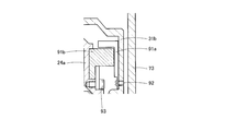
- the rotation sensor 75 is provided between the support member disk part 31b of the rotor support member 31 and the axially opposed surfaces of the partition disk part 24a.
- the sensor rotor 91a is composed of a magnet attached to the support member disk portion 31b with screws 92.
- the sensor stator 91b is constituted by a Hall element attached to the opposing surface of the partition disk portion 24a by screws 93. Both face each other through an axial gap.
- the sensor rotor 91b may have a reverse L-shaped cross section, and a radial gap may be formed between the horizontal portion of the sensor rotor 91b and the sensor stator 91a.
- Both the power terminal box 76 and the connector insertion part 78 are provided in the housing 16 (see FIG. 9).
- the power terminal box 76 is provided with a storage recess 94 within the thickness range of the rear end surface of the housing 16, and a power terminal 82 is provided inside the storage recess 94.
- a communication hole 95 communicating with the inside of the housing 16 is provided in the back of the storage recess 94.
- the open surface of the storage recess 94 is closed by the lid member 96.
- the lid member 96 is provided with a cable hole 97 through which the power cable 84 is passed.
- a work hole 80 is provided in the wall surface of the housing 16. This working hole 80 is normally closed by a lid 81.
- the lead wire 83 on the electric motor 11 side is connected to the power supply terminal 82 through the communication hole 95, and the power supply cable 84 is drawn through the cable hole 97, and the connection terminal is connected to the power supply terminal 82. Both are coupled to the power terminal 82 by a fastening screw 85.
- the connector insertion portion 78 is provided side by side with the power supply terminal box 76 on the rear end surface of the housing 16.
- the connector insertion portion 78 is provided with a concave portion 99 on the rear end surface of the housing 16, and a lead wire hole 100 (see FIG. 8) that communicates the interior of the concave portion 99 with the inside of the housing 16.
- the lead wire 101 of the rotation sensor 84 is connected to the inside of the recess 99 through the lead wire hole 100.
- a signal cable connector (not shown) is inserted into the connector insertion portion 78.
- the configuration in which both the power terminal box 76 and the connector insertion portion 78 are provided in the housing 16 simplifies the configuration of the rear cover 73 and can be configured by a thin metal plate, a resin plate, or the like.
Landscapes
- Engineering & Computer Science (AREA)
- Power Engineering (AREA)
- Microelectronics & Electronic Packaging (AREA)
- Arrangement Or Mounting Of Propulsion Units For Vehicles (AREA)
- Retarders (AREA)
- General Details Of Gearings (AREA)
Abstract
Description
[実施形態1]
[実施形態2]
なお、この場合のハブユニット15は、いわゆる第3世代の変形形式ということができる。
[実施形態3]
12 減速ユニット
13 入力軸
14 出力部材
15 ハブユニット
16 ハウジング
17 円筒部
18 前端部
19 突出部
20 隔壁部材
20a ボルト
21 外方部材
22 フランジ
23 ボルト
24 隔壁
24a 隔壁円板部
24b 隔壁円筒部
25 センター穴
26 フィン
27 サスペンション連結部
28 ステータ
29 ロータ
31 ロータ支持部材
31a 支持部材円筒部
31b 支持部材円板部
31c ボス部
32 フランジ円筒部
35 キー止め部
36 オイルシール部材
38 キー止め
39 サンギヤ
41 キー止め部
42 リングギヤ
43 ピニオンギヤ
44 針状ころ軸受
45 ピニオンピン
46 内方部材
47 結合軸部
48 転がり軸受
49 軸受支持部
50 ナット
51 軸穴
52 、53 フランジ
54 ブリッジ
55 ピニオンギヤ収納部
56 止めネジ
57 スラスト板
58、59 転がり軸受
60 位置決め穴
61、62 段差部
63 止め輪
64 間座
65 窓穴
66 閉鎖部
67 止めネジ
68 給油口
69 排油口
70 オイルシール部材
71 溝
72 閉塞ネジ
73 リヤカバー
74 フィン
75 回転センサー
75a センサーステータ
75b センサーロータ
76 電源端子ボックス
76a 電源端子
77 センサーカバー
78 コネクタ差込部
79 挿通穴
80 作業用穴
81 蓋
82 電源端子
83 リード線
84 電源ケーブル
84a ケーブル穴
85 締付けネジ
86 ハブ
87 内輪
88 外輪
89 ボール
89a、89b ハブ軸受
90 ハブボルト
91a センサーロータ
91b センサーステータ
92、93 ビス
94 収納凹部
95 連通穴
96 蓋部材
97 ケーブル穴
99 凹部
100 リード線穴
Claims (12)
- 電動モータ、前記電動モータの出力によって駆動される入力軸を備えた減速ユニット、前記減速ユニットの出力部材によって回転駆動されるハブユニット及び前記電動モータと前記減速ユニットを収納したハウジングとから構成され、前記ハウジング内において前記電動モータは減速ユニットの外径側に配置され、前記ハウジングの電動モータ及び減速ユニットの収納部分の後端部が開放され、その開放部分がリヤカバーによって閉鎖され、前記電動モータに対する電源供給手段が前記ハウジングに設けられた電気自動車用駆動装置において、前記電源供給手段が、前記ハウジングの後端面に設けられた収納凹部と、その収納凹部の内部に設けられた電源端子と、収納凹部とハウジング内部とに通じた連通穴と、収納凹部の蓋部材とからなる電源端子ボックスによって構成され、電動モータのリード線が前記連通穴を通って電源端子に接続され、前記電源端子ボックスに電源ケーブルの接続端子の挿通穴が設けられたことを特徴とする電気自動車用駆動装置。
- 前記ハウジングに前記電動モータの収納部と減速ユニットの収納部を仕切る隔壁が設けられ、その隔壁と前記電動モータのロータ支持部材との間にアキシャルギャップ形又はラジアルギャップ形の回転センサーが設けられ、前記回転センサーのリード線端子が前記ケーシングに設けたコネクタ差込部に設けられたことを特徴とする請求項2に記載の電気自動車用駆動装置。
- 前記一対の軸受が共に前記の出力部材によって支持されたことを特徴とする請求項1又は2に記載の電気自動車用駆動装置。
- 前記入力軸を支持する一対の軸受は、いずれも前記入力軸と電動モータのロータ支持部材との嵌合部よりもアウトボード側に配置される支持構造をとることを特徴とする請求項3に記載の電気自動車用駆動装置。
- 前記出力部材が、前記減速ユニットの減速回転部材の軸方向両側に配置された一対のフランジを有し、前記減速回転部材の支持ピンの両端部が各フランジに固定されることによって前記フランジ相互が結合一体化され、各フランジの内径面と前記入力軸との間にそれぞれ前記の各軸受が介在されたことを特徴とする請求項3又は4に記載の電気自動車用駆動装置。
- 前記減速ユニットが、入力軸に同軸状に設けられるサンギヤ及びリングギヤ、前記サンギヤとリングギヤの間に円周方向等配に設けられる複数のピニオンギヤ、前記ピニオンギヤを保持するキャリヤとからなる遊星ギヤ形式であることを特徴とする請求項5に記載の電気自動車用駆動装置。
- 前記減速ユニットが、遊星ギヤ形式であり、前記フランジ相互が周方向に所要の間隔をおいて設けられたブリッジによって一体化され、そのブリッジ相互間にピニオンギヤが収納され、そのピニオンピンの両端部が前記のフランジによってそれぞれ支持されたことを特徴とする請求項6に記載の電気自動車用駆動装置。
- 前記一対の軸受がそれぞれ転がり軸受によって構成され、一対の転がり軸受の外輪相互間に環状の間座が介在され、前記間座は前記減速回転部材と対向する部分において干渉回避のための窓穴が設けられ、前記間座の固定ビスが前記ブリッジ部外径面からねじ込まれたことを特徴とする請求項3から7のいずれかに記載の電気自動車用駆動装置。
- 前記減速ユニットが、前記電動モータの内径側に配置され、減速ユニットと電動モータの収納部がハウジングに設けた隔壁によって区画されたたことを特徴とする請求項3から8のいずれかに記載の電気自動車用駆動装置。
- 前記隔壁が、ハウジングに設けた隔壁基部と、その隔壁基部に連結固定された隔壁部材とにより構成されたことを特徴とする請求項9に記載の電気自動車用駆動装置。
- 前記電動モータのステータが、前記減速ユニットの外径側においてハウジングに固定され、ロータが前記ステータと前記隔壁の間に配置され、前記ロータの支持部材が前記入力軸に嵌合一体化されたことを特徴とする請求項10に記載の電気自動車用駆動装置。
- 前記電動モータ及び減速ユニットを収納したハウジングに前記ハブユニットの外方部材のフランジを固定したことを特徴とする請求項3から11のいずれかに記載の電気自動車用駆動装置。
Priority Applications (3)
| Application Number | Priority Date | Filing Date | Title |
|---|---|---|---|
| US14/003,694 US9362804B2 (en) | 2011-03-07 | 2011-03-08 | Drive device for electric vehicle |
| CN201180000159.8A CN102792565B (zh) | 2011-03-07 | 2011-03-08 | 电动车用驱动装置 |
| EP11860210.1A EP2685613B1 (en) | 2011-03-07 | 2011-03-08 | Drive device for electric vehicle |
Applications Claiming Priority (2)
| Application Number | Priority Date | Filing Date | Title |
|---|---|---|---|
| JP2011-049189 | 2011-03-07 | ||
| JP2011049189A JP5676314B2 (ja) | 2011-03-07 | 2011-03-07 | 電気自動車用駆動装置 |
Publications (1)
| Publication Number | Publication Date |
|---|---|
| WO2012120649A1 true WO2012120649A1 (ja) | 2012-09-13 |
Family
ID=46797652
Family Applications (1)
| Application Number | Title | Priority Date | Filing Date |
|---|---|---|---|
| PCT/JP2011/055397 Ceased WO2012120649A1 (ja) | 2011-03-07 | 2011-03-08 | 電気自動車用駆動装置 |
Country Status (5)
| Country | Link |
|---|---|
| US (1) | US9362804B2 (ja) |
| EP (1) | EP2685613B1 (ja) |
| JP (1) | JP5676314B2 (ja) |
| CN (1) | CN102792565B (ja) |
| WO (1) | WO2012120649A1 (ja) |
Families Citing this family (11)
| Publication number | Priority date | Publication date | Assignee | Title |
|---|---|---|---|---|
| JP5509288B2 (ja) * | 2012-10-05 | 2014-06-04 | 本田技研工業株式会社 | 車両用駆動装置 |
| DE102013204784B4 (de) * | 2013-03-19 | 2018-01-11 | Robert Bosch Gmbh | Elektrische Fahrzeugachsenvorrichtung |
| KR101441813B1 (ko) | 2013-06-25 | 2014-09-18 | 현대위아 주식회사 | 전기자동차의 후륜 구동장치 |
| CN103762776B (zh) * | 2014-01-29 | 2017-04-26 | 江苏雷利电机股份有限公司 | 引线连接装置、应用其的小型电机及小型电机的装配方法 |
| JP6790947B2 (ja) * | 2017-03-21 | 2020-11-25 | トヨタ自動車株式会社 | インホイールモータユニット |
| US20190028008A1 (en) * | 2017-07-18 | 2019-01-24 | Hyundai Mobis Co., Ltd | In-wheel working device |
| EP3457542A1 (en) * | 2017-09-15 | 2019-03-20 | Nidec Corporation | Drive device |
| JP2020132037A (ja) * | 2019-02-22 | 2020-08-31 | Ntn株式会社 | インホイールモータ駆動装置 |
| EP3719352A1 (de) * | 2019-04-05 | 2020-10-07 | Flender GmbH | Getriebegehäuse, sensormontagekit und getriebe |
| JP2025504250A (ja) * | 2022-02-14 | 2025-02-06 | ビーテミア インク. | モータ内変速機を伴う高密度アクチュエータ |
| JP7758084B2 (ja) * | 2024-03-19 | 2025-10-22 | 株式会社明電舎 | 回転機 |
Citations (5)
| Publication number | Priority date | Publication date | Assignee | Title |
|---|---|---|---|---|
| JP2000052788A (ja) * | 1998-08-06 | 2000-02-22 | Araco Corp | 電動車両 |
| JP2001032888A (ja) | 1999-07-23 | 2001-02-06 | Aisin Aw Co Ltd | 電気自動車用ドライブユニット |
| JP2006282158A (ja) * | 2005-03-08 | 2006-10-19 | Honda Motor Co Ltd | 車両用ホイール駆動装置 |
| JP2007191035A (ja) * | 2006-01-19 | 2007-08-02 | Bridgestone Corp | インホイールモータシステム |
| JP2010105476A (ja) * | 2008-10-29 | 2010-05-13 | Aisin Aw Co Ltd | 車両用駆動装置 |
Family Cites Families (19)
| Publication number | Priority date | Publication date | Assignee | Title |
|---|---|---|---|---|
| CN2052983U (zh) * | 1989-09-01 | 1990-02-14 | 李灵健 | 带减速器的永磁直流无刷电机 |
| US6590306B2 (en) * | 2001-02-26 | 2003-07-08 | Yamaha Hatsudoki Kabushiki Kaisha | Electric motor driven wheel |
| CN2534092Y (zh) * | 2002-03-29 | 2003-02-05 | 潘若望 | 电动自行车驱动装置 |
| JP2004120909A (ja) * | 2002-09-26 | 2004-04-15 | Mitsubishi Motors Corp | インホイールモータの配線構造 |
| JP4173345B2 (ja) | 2002-10-03 | 2008-10-29 | 本田技研工業株式会社 | 車両の駆動装置 |
| TWI283103B (en) * | 2004-02-06 | 2007-06-21 | Yamaha Motor Co Ltd | Rotating electric machine and electrically driven vehicle |
| JP2005231564A (ja) * | 2004-02-23 | 2005-09-02 | Ntn Corp | 電動式車輪駆動装置 |
| JP2007022386A (ja) * | 2005-07-19 | 2007-02-01 | Ntn Corp | 電動式車輪駆動装置 |
| JP2007068340A (ja) * | 2005-08-31 | 2007-03-15 | Toyota Motor Corp | 車両の電源装置 |
| JP4894215B2 (ja) * | 2005-10-05 | 2012-03-14 | 日産自動車株式会社 | インホイールドライブユニット |
| JP4337803B2 (ja) * | 2005-10-28 | 2009-09-30 | トヨタ自動車株式会社 | ハイブリッド車両の駆動装置 |
| JP3960553B1 (ja) * | 2006-03-31 | 2007-08-15 | 本田技研工業株式会社 | インホイールモータ車のホイール回転装置 |
| CN101490929B (zh) * | 2006-07-12 | 2011-08-31 | 丰田自动车株式会社 | 马达组件 |
| JP2008044587A (ja) * | 2006-08-18 | 2008-02-28 | Junichi Yoshimori | ハイブリット機能を可能にしたオーバーランニングクラッチと減速ギャーを組み込んだ発電機兼用駆動モーター |
| JP2009219271A (ja) * | 2008-03-11 | 2009-09-24 | Ntn Corp | モータ駆動装置およびインホイールモータ駆動装置 |
| JP4873264B2 (ja) * | 2008-05-30 | 2012-02-08 | アイシン・エィ・ダブリュ株式会社 | 駆動装置 |
| JP5383340B2 (ja) * | 2009-06-18 | 2014-01-08 | アイシン精機株式会社 | 電動機の結線構造および結線方法 |
| JP5407581B2 (ja) * | 2009-06-18 | 2014-02-05 | アイシン精機株式会社 | インホイールモータ |
| JP5509713B2 (ja) | 2009-08-04 | 2014-06-04 | 日産自動車株式会社 | インホイールモータユニット |
-
2011
- 2011-03-07 JP JP2011049189A patent/JP5676314B2/ja not_active Expired - Fee Related
- 2011-03-08 WO PCT/JP2011/055397 patent/WO2012120649A1/ja not_active Ceased
- 2011-03-08 US US14/003,694 patent/US9362804B2/en not_active Expired - Fee Related
- 2011-03-08 EP EP11860210.1A patent/EP2685613B1/en active Active
- 2011-03-08 CN CN201180000159.8A patent/CN102792565B/zh not_active Expired - Fee Related
Patent Citations (5)
| Publication number | Priority date | Publication date | Assignee | Title |
|---|---|---|---|---|
| JP2000052788A (ja) * | 1998-08-06 | 2000-02-22 | Araco Corp | 電動車両 |
| JP2001032888A (ja) | 1999-07-23 | 2001-02-06 | Aisin Aw Co Ltd | 電気自動車用ドライブユニット |
| JP2006282158A (ja) * | 2005-03-08 | 2006-10-19 | Honda Motor Co Ltd | 車両用ホイール駆動装置 |
| JP2007191035A (ja) * | 2006-01-19 | 2007-08-02 | Bridgestone Corp | インホイールモータシステム |
| JP2010105476A (ja) * | 2008-10-29 | 2010-05-13 | Aisin Aw Co Ltd | 車両用駆動装置 |
Also Published As
| Publication number | Publication date |
|---|---|
| EP2685613A1 (en) | 2014-01-15 |
| US20130342056A1 (en) | 2013-12-26 |
| EP2685613A4 (en) | 2016-01-27 |
| CN102792565A (zh) | 2012-11-21 |
| JP2012183946A (ja) | 2012-09-27 |
| CN102792565B (zh) | 2017-02-08 |
| US9362804B2 (en) | 2016-06-07 |
| EP2685613B1 (en) | 2020-01-22 |
| JP5676314B2 (ja) | 2015-02-25 |
Similar Documents
| Publication | Publication Date | Title |
|---|---|---|
| JP5685113B2 (ja) | 電気自動車用駆動装置 | |
| JP5685111B2 (ja) | 電気自動車用駆動装置 | |
| JP5685112B2 (ja) | 電気自動車用駆動装置 | |
| JP5676314B2 (ja) | 電気自動車用駆動装置 | |
| JP5604338B2 (ja) | 電気自動車用駆動装置 | |
| JP2013071698A (ja) | 電気自動車用駆動装置 | |
| JP5956552B2 (ja) | 電気自動車用駆動装置 | |
| JP2013040659A (ja) | 電気自動車用駆動装置 | |
| JP2006254570A (ja) | ハイブリッド駆動装置 | |
| JP2007104764A (ja) | ハイブリッド車両の駆動装置 |
Legal Events
| Date | Code | Title | Description |
|---|---|---|---|
| WWE | Wipo information: entry into national phase |
Ref document number: 201180000159.8 Country of ref document: CN |
|
| 121 | Ep: the epo has been informed by wipo that ep was designated in this application |
Ref document number: 11860210 Country of ref document: EP Kind code of ref document: A1 |
|
| WWE | Wipo information: entry into national phase |
Ref document number: 14003694 Country of ref document: US |
|
| NENP | Non-entry into the national phase |
Ref country code: DE |
|
| REEP | Request for entry into the european phase |
Ref document number: 2011860210 Country of ref document: EP |
|
| WWE | Wipo information: entry into national phase |
Ref document number: 2011860210 Country of ref document: EP |