WO2012120727A1 - 防水構造、電子機器、及び防水構造の製造方法 - Google Patents
防水構造、電子機器、及び防水構造の製造方法 Download PDFInfo
- Publication number
- WO2012120727A1 WO2012120727A1 PCT/JP2011/075318 JP2011075318W WO2012120727A1 WO 2012120727 A1 WO2012120727 A1 WO 2012120727A1 JP 2011075318 W JP2011075318 W JP 2011075318W WO 2012120727 A1 WO2012120727 A1 WO 2012120727A1
- Authority
- WO
- WIPO (PCT)
- Prior art keywords
- opening
- closing member
- waterproof structure
- disposed
- outer casing
- Prior art date
- Legal status (The legal status is an assumption and is not a legal conclusion. Google has not performed a legal analysis and makes no representation as to the accuracy of the status listed.)
- Ceased
Links
Images




Classifications
-
- H—ELECTRICITY
- H04—ELECTRIC COMMUNICATION TECHNIQUE
- H04M—TELEPHONIC COMMUNICATION
- H04M1/00—Substation equipment, e.g. for use by subscribers
- H04M1/02—Constructional features of telephone sets
- H04M1/18—Telephone sets specially adapted for use in ships, mines, or other places exposed to adverse environment
-
- G—PHYSICS
- G06—COMPUTING OR CALCULATING; COUNTING
- G06F—ELECTRIC DIGITAL DATA PROCESSING
- G06F1/00—Details not covered by groups G06F3/00 - G06F13/00 and G06F21/00
- G06F1/16—Constructional details or arrangements
- G06F1/1613—Constructional details or arrangements for portable computers
- G06F1/1633—Constructional details or arrangements of portable computers not specific to the type of enclosures covered by groups G06F1/1615 - G06F1/1626
- G06F1/1656—Details related to functional adaptations of the enclosure, e.g. to provide protection against EMI, shock, water, or to host detachable peripherals like a mouse or removable expansions units like PCMCIA cards, or to provide access to internal components for maintenance or to removable storage supports like CDs or DVDs, or to mechanically mount accessories
-
- H—ELECTRICITY
- H05—ELECTRIC TECHNIQUES NOT OTHERWISE PROVIDED FOR
- H05K—PRINTED CIRCUITS; CASINGS OR CONSTRUCTIONAL DETAILS OF ELECTRIC APPARATUS; MANUFACTURE OF ASSEMBLAGES OF ELECTRICAL COMPONENTS
- H05K13/00—Apparatus or processes specially adapted for manufacturing or adjusting assemblages of electric components
-
- H—ELECTRICITY
- H05—ELECTRIC TECHNIQUES NOT OTHERWISE PROVIDED FOR
- H05K—PRINTED CIRCUITS; CASINGS OR CONSTRUCTIONAL DETAILS OF ELECTRIC APPARATUS; MANUFACTURE OF ASSEMBLAGES OF ELECTRICAL COMPONENTS
- H05K5/00—Casings, cabinets or drawers for electric apparatus
- H05K5/06—Hermetically-sealed casings
-
- Y—GENERAL TAGGING OF NEW TECHNOLOGICAL DEVELOPMENTS; GENERAL TAGGING OF CROSS-SECTIONAL TECHNOLOGIES SPANNING OVER SEVERAL SECTIONS OF THE IPC; TECHNICAL SUBJECTS COVERED BY FORMER USPC CROSS-REFERENCE ART COLLECTIONS [XRACs] AND DIGESTS
- Y10—TECHNICAL SUBJECTS COVERED BY FORMER USPC
- Y10T—TECHNICAL SUBJECTS COVERED BY FORMER US CLASSIFICATION
- Y10T29/00—Metal working
- Y10T29/49—Method of mechanical manufacture
- Y10T29/49826—Assembling or joining
Definitions
- the present invention relates to a waterproof structure in an opening of a casing of an electronic device, an electronic device including the waterproof structure, and a method for manufacturing the waterproof structure.
- An electronic device such as a portable terminal provided with a display panel is generally configured such that a display panel is disposed to face an opening of a housing, and the opening is closed by a protective panel. And such an electronic device has the waterproof structure for airtightly closing an opening with a protection panel.
- this type of waterproof structure for example, configurations described in Patent Documents 1 and 2 are known.
- FIG. 1 shows a cross-sectional view of an example of a waterproof structure related to the present invention.
- a waterproof structure 101 related to the present invention includes a casing 107 having an opening 108, a liquid crystal display panel 110 disposed inside the casing 107 so as to face the opening 108, and a casing 107. And a protection panel 111 that closes the opening 108.
- the protection panel 111 is disposed so as to protect the display surface of the liquid crystal display panel 110.
- the casing 107 is configured by engaging a first outer casing 107a and a second outer casing 107b.
- An O-ring 113 is sandwiched between the engaging portions of the first outer casing 107a and the second outer casing 107b, and airtightness is ensured.
- the protective panel 111 is disposed outside the first outer casing 107a, and the opening 108 is closed by being adhered to the peripheral portion of the opening 108 with a double-sided adhesive tape 116.
- the waterproof structure related to the present invention has the following problems.
- the protective panel is directly fixed to the opening of the housing with an adhesive member, there is a possibility that the protective panel may be directly damaged by being subjected to an impact applied when the electronic device is dropped.
- the third problem is that the protection panel in the above-described waterproof structure is attached to the opening of the housing by an adhesive member, so that the protection panel that faces the liquid crystal display panel according to variations in the attachment position of the protection panel The position of the center of the opposite surface is displaced from the center of the opening. As a result, the center of the display surface of the liquid crystal display panel and the center of the opposing surface of the protective panel are shifted, resulting in a problem of assembly failure.
- an object of the present invention is to provide a waterproof structure, an electronic device, and a method for manufacturing a waterproof structure that can solve any of the above-described technical problems and can improve waterproofness and impact resistance.
- a waterproof structure includes a housing having an opening, a closing member disposed inside the housing and closing the opening, and a closing member in a direction orthogonal to the opening surface of the opening.
- a waterproof member disposed on one surface and a holding member disposed on the other surface of the closing member in a direction orthogonal to the opening surface of the opening and slidably holding the closing member in a direction parallel to the opening surface of the opening and an elastic member that is disposed in contact with the end of the closing member and supports the closing member so as to be displaceable in a direction parallel to the opening surface of the opening.
- the closing member is sandwiched between the waterproof member and the holding member and supported by the housing.
- the electronic device according to the present invention includes the waterproof structure of the present invention.
- the waterproof structure manufacturing method includes a waterproof member disposed on one surface of the closing member in a direction orthogonal to the opening surface of the opening, the blocking member disposed inside the housing closing the opening of the housing.
- the closing member is sandwiched between the member and the holding member disposed on the other surface of the closing member in the direction orthogonal to the opening surface of the opening, and the closing member is opened by the holding member abutted on the end of the closing member. It is supported so that it can be displaced in a direction parallel to the opening surface.
- the closing member is movably supported by the sliding member and the elastic member is in contact with the closing member, it is possible to improve waterproofness and impact resistance.
- FIG. 2 is a perspective view of the electronic apparatus according to the first embodiment.
- FIG. 3 is a cross-sectional view of the main part of the waterproof structure provided in the electronic device of the first embodiment.
- the electronic device of the first embodiment includes a waterproof structure 1 that prevents liquid from entering the inside of the housing 7 from the outside.
- the waterproof structure 1 includes a housing 7 having an opening 8, a liquid crystal display panel 10 as a display element disposed inside the housing 7 so as to face the opening 8, A protective panel 11 as a blocking member disposed inside to close the opening 8, an O-ring 12 as a waterproof member disposed on one surface of the protective panel 11 in a direction orthogonal to the opening surface of the opening 8, and the opening 8 A sliding plate 13 as a holding member which is disposed on the other surface of the protective panel 11 in a direction perpendicular to the opening surface of the opening and which holds the protective panel 11 in a direction parallel to the opening surface of the opening 8; A spring member 14 as an elastic member that is disposed in contact with an end portion of the protective panel 11 in a direction parallel to the opening surface of 8 and supports the protective panel 11 so as to be displaceable in a direction parallel to the opening surface of the opening 8; Is provided.
- the opening surface of the opening 8 refers to a virtual surface including the periphery of the opening 8.
- the housing 7 includes a first outer housing 7 a disposed on the outer surface side of the protective panel 11 in the direction orthogonal to the opening surface of the opening 8, and the protective panel 11 in the direction orthogonal to the opening surface of the opening 8. And a second outer casing 7b disposed on the inner surface side.
- the first outer casing 7 a has an opening 8 a, and a facing surface 16 a that faces one surface of the protective panel 11 is formed at the peripheral portion of the opening 8 a.
- the second outer casing 7 b has an opening 8 b, and a facing surface 16 b that faces the other surface of the protective panel 11 is formed at the periphery of the opening 8 b.
- the opening 8a of the first outer casing 7a is formed smaller than the opening 8b of the second outer casing 7b.
- the first outer casing 7a and the second outer casing 7b are fixed by screws 17 with the opposing surfaces 16a and 16b facing each other, and between the first outer casing 7a and the second outer casing 7b.
- a protective panel 11 is arranged.
- the liquid crystal display panel 10 is provided in the opening 8b of the second outer casing 7b, and the display surface of the liquid crystal display panel 10 is disposed to face the protective panel 11.
- a display element it is not limited to a liquid crystal display panel,
- other display elements such as an organic electroluminescent (EL) panel, may be used.
- EL organic electroluminescent
- the protective panel 11 is formed in a flat plate shape from a light-transmitting material, and the display surface of the liquid crystal display panel 10 can be viewed from the outside of the housing 7.
- the protection panel 11 has a larger area than the display surface of the liquid crystal display panel 10.
- the protective panel 11 is sandwiched between the O-ring 12 and the sliding plate 13 and supported by the housing 7.
- the O-ring 12 is engaged with a groove 18 provided on the facing surface 16a of the first outer casing 7a, and is disposed along the entire circumference of the protective panel 11.
- first outer casing 7a is formed with an engaging recess 20a that engages with the second outer casing 7b.
- the second outer casing 7b is formed with an engaging convex portion 20b that engages with the engaging concave portion 20a of the first outer casing 7a.
- another O-ring 21 is provided between the engaging concave portion 20a and the engaging convex portion 20b. The engaging part with the part 20b is airtightly closed.
- FIG. 4 is a perspective view of the sliding plate 13 of the waterproof structure 1 according to the first embodiment.
- the sliding plate 13 is made of, for example, a resin material such as POM (polyacetal) having excellent slidability, or silicon rubber.
- a tape material made of tetrafluoroethylene joined to a cushion material may be used.
- the sliding plate 13 is formed in an annular plate shape such as a quadrangular frame shape, and the protection plate 11 is positioned on the opposite side of the O-ring 12 with respect to the protection panel 11. It is arranged along the entire circumference. For this reason, the opening 8 of the housing 7 is hermetically closed by the protective panel 11 and the O-ring 12.
- the material excellent in waterproofness such as a polymeric material, as a sliding plate.
- a holding recess 23 that holds the spring member 14 is formed at a position facing the end surface of the protection panel 11, and the spring member 14 is held in the holding recess 23.
- the spring member 14 is made of a resin material such as a metal material or an elastomer, and has an elastic deformation piece 14 a that abuts against the end surface of the protection panel 11.
- the spring member 14 holds the protection panel 11 so as to be displaceable in the direction of arrow a in FIG. 3 parallel to the opening surface of the opening 8 by elastically displacing the elastic deformation piece 14a abutted against the end surface of the protection panel 11. To do. Although not shown, the spring member 14 is disposed along each side of the outer peripheral portion of the protection panel 11.
- FIG. 5 sectional drawing for demonstrating operation
- movement of the waterproof structure 1 in 1st Embodiment is shown.
- the electronic device when an external device is subjected to an impact when the electric device is dropped, the electronic device operates in the same manner as described above, and a relative displacement occurs between the protective panel 11 and the housing 7.
- the elastic deformation piece 14 a of the spring member 14 is elastically deformed, so that the displacement amount of the protective panel 11 and the housing 7 is absorbed, and the protective panel 11 is It slides while being supported by the sliding plate 13. Accordingly, since the airtightness is maintained with the O-ring 12 being sandwiched between the protective panel 11 and the first outer casing 7a slid in the direction parallel to the opening surface of the opening 8, the waterproof property is maintained. Well kept.
- the protection panel 11 is slidably supported by the sliding plate 13, and the spring member 14 is in contact with the protection panel 11. Even when the outer dimensions of the protective panel 11 or the casing 7 are deformed or an external impact is applied, the airtightness can be maintained. As a result, according to the present embodiment, it is possible to improve waterproofness, prevent damage to the protective panel 11 and the housing 7 due to impact, and improve impact resistance.
- the restriction on the linear expansion coefficient of the material that can be used for the constituent member is relaxed, and the degree of freedom of the combination of the materials that can be used as the constituent member is increased. It becomes possible to do.
- the outer peripheral portion of the protection panel 11 is held by the elastic deformation pieces 14 a of the spring member 14 arranged along each side of the protection panel 11. For this reason, it becomes easy to assemble so that the center of the facing surface of the protection panel 11 facing the liquid crystal display panel 10 and the center of the display surface of the liquid crystal display panel 10 coincide with each other, thereby reducing the occurrence of defective assembly. Is possible.
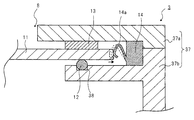
- FIG. 6 sectional drawing of the waterproof structure in 2nd Embodiment is shown.
- the waterproof structure in the second embodiment simplifies the configuration of the casing, and includes a screw 17 for connecting the first outer casing 7a and the second outer casing 7b constituting the casing 7, and the first outer casing 7b.
- the difference from the first embodiment is that the O-ring 21 arranged between the casing 7a and the second outer casing 7b is omitted.
- the waterproof structure 2 in the second embodiment includes a casing 27 that is a combination of a first outer casing 27 a and a second outer casing 27 b, and the first outer casing 27 a
- the second outer casing 27b is joined by, for example, an adhesive.
- the first outer casing 27a and the second outer casing 27b may be joined by welding instead of using an adhesive.
- the present embodiment may be configured such that a component such as a liquid crystal display panel is not disposed at a position corresponding to the opening 8, and as in the first embodiment described above,
- the liquid crystal display panel 10 and various components may be arranged at positions corresponding to the openings 8 of the housing 7.
- the waterproofness and impact resistance can be improved as in the first embodiment.
- the shapes of the first outer casing 27a and the second outer casing 27b are simplified and configured. Can be simplified.
- FIG. 7 sectional drawing of the waterproof structure in 3rd Embodiment is shown.
- the waterproof structure in the third embodiment is that the sliding plate 13 is disposed outside the housing 7 with the protective panel 11 interposed therebetween, and the O-ring 12 is disposed inside the housing 7.
- This is different from the second embodiment. That is, in the third embodiment, the arrangement of the sliding plate 13 and the O-ring 12 in the second embodiment is reversed.
- the waterproof structure 3 in the third embodiment includes a casing 37 that is a combination of a first outer casing 37 a and a second outer casing 37 b.
- the sliding plate 13 is disposed in contact with the outer surface of the protective panel 11 disposed in the opening 8.
- the second outer casing 37b is provided with a groove 38 with which the O-ring 12 is engaged.
- the O-ring 12 is disposed in contact with the inner surface of the protective panel 11 disposed in the opening 8.
- the waterproofness and impact resistance can be improved as in the first embodiment.
- the third embodiment can increase the degree of freedom of assembly of the electronic device by changing the arrangement of the sliding plate 13 and the O-ring 12 as necessary.
- FIG. 8 sectional drawing of the waterproof structure in 4th Embodiment is shown.
- the waterproof structure in the fourth embodiment is different from that in the first embodiment in that the liquid crystal display panel is fixed to the protective panel.
- the periphery of the display surface of the liquid crystal display panel 10 is bonded to the protective panel 11 using an adhesive (not shown). 10 is fixed to the inner surface of the protective panel 11.
- a predetermined gap is provided between the outer peripheral portion of the liquid crystal display panel 10 and the opening 8b of the second outer casing 7b, and the liquid crystal display panel 10 that moves together with the protective panel 11 is connected to the second outer casing. It is comprised so that it may not contact
- the protection panel 11 slidably held in the direction parallel to the opening surface of the opening 8 by the sliding plate 13 and the spring member 14 and the liquid crystal display panel 10 move integrally.
- the liquid crystal display panel 10 that moves together with the protective panel 11 is prevented from being damaged by impact by providing a predetermined gap so that the liquid crystal display panel 10 does not contact the opening 8b of the second outer casing 7b. Is done. For this reason, by positioning and fixing the liquid crystal display panel 10 with respect to the protection panel 11, it becomes possible to accurately position the relative position between the protection panel 11 and the liquid crystal display panel 10.
- the waterproofness and impact resistance can be improved as in the first embodiment.
- the liquid crystal display panel 10 is provided by providing a predetermined gap between the liquid crystal display panel 10 fixed to the protective panel 11 and the opening 8b of the second outer casing 7b. Can be prevented from being damaged by impact. Further, according to the fourth embodiment, it is possible to prevent relative displacement between the protective panel 11 and the liquid crystal display panel 10 in the manufacturing process as compared with the first embodiment.
- FIG. 9 sectional drawing of the waterproof structure in 5th Embodiment is shown.
- the waterproof structure in the fifth embodiment is different from the first embodiment in that a bumper member made of an elastic body is provided instead of the spring member 14.
- a bumper member 51 is provided in the holding recess 23 of the housing 7 so that one end is in contact with the end surface of the protective panel 11.
- the bumper member 51 is formed in a rectangular frame shape by, for example, an elastomer, and the protective panel 11 is fitted and held in an inner peripheral portion of the frame shape.
- the waterproofness and impact resistance can be improved as in the first embodiment.
- the bumper member 51 by using the bumper member 51, it is possible to omit a portion that may be buckled, such as an elastic deformation piece. It is possible to increase the reliability of the operation for supporting the displacement.
- the waterproof structure according to the present invention can be preferably applied to an electronic device including a display panel such as a portable music player, a portable television, and a portable disk player.
- a display panel such as a portable music player, a portable television, and a portable disk player.
- the present invention is not limited to the portable electronic device described above, and may be applied to other electronic devices such as a notebook personal computer (PC), a desktop PC, a camera, and a watch.
- PC notebook personal computer
- desktop PC a notebook personal computer
- camera a camera
- watch a watch
Landscapes
- Engineering & Computer Science (AREA)
- Computer Hardware Design (AREA)
- General Engineering & Computer Science (AREA)
- Theoretical Computer Science (AREA)
- Microelectronics & Electronic Packaging (AREA)
- Signal Processing (AREA)
- Human Computer Interaction (AREA)
- Physics & Mathematics (AREA)
- General Physics & Mathematics (AREA)
- Manufacturing & Machinery (AREA)
- Casings For Electric Apparatus (AREA)
- Telephone Set Structure (AREA)
Abstract
Description
図2に、第1の実施形態の電子機器の斜視図を示す。図3に、第1の実施形態の電子機器が備える防水構造の要部の断面図を示す。
図6に、第2の実施形態における防水構造の断面図を示す。第2の実施形態における防水構造は、筐体の構成の簡素化を図り、筐体7を構成する第1の外筐7aと第2の外筐7bとを結合するネジ17、第1の外筐7aと第2の外筐7bとの間に配置されたOリング21が省かれた点が、第1の実施形態と異なっている。
図7に、第3の実施形態における防水構造の断面図を示す。第3の実施形態における防水構造は、保護パネル11を間に挟んで、筐体7の外側に摺動プレート13が配置されると共に、筐体7の内側にOリング12が配置された点が、第2の実施形態と異なっている。つまり、第3の実施形態では、第2の実施形態における摺動プレート13とOリング12の配置が逆にされている。
図8に、第4の実施形態における防水構造の断面図を示す。第4の実施形態における防水構造は、液晶表示パネルが保護パネルに固定されている点が、第1の実施形態と異なっている。
図9に、第5の実施形態における防水構造の断面図を示す。第5の実施形態における防水構造は、バネ部材14の代わりに、弾性体からなるバンパー部材を備える点が、第1の実施形態と異なっている。
7 筐体
7a 第1の外筐
7b 第2の外筐
8(8a,8b) 開口
11 保護パネル
12 Oリング
13 摺動プレート
14 バネ部材
Claims (8)
- 開口を有する筐体と、
前記筐体の内部に配置され、前記開口を塞ぐ閉塞部材と、
前記開口の開口面に直交する方向における前記閉塞部材の一方の面に配置された防水部材と、
前記開口の開口面に直交する方向における前記閉塞部材の他方の面に配置され、前記閉塞部材を前記開口の開口面に平行な方向に摺動可能に保持する保持部材と、
前記閉塞部材の端部に当接して配置され、前記閉塞部材を前記開口の開口面に平行な方向に変位可能に支持する弾性部材と、を備え、
前記閉塞部材は、前記防水部材と前記保持部材との間に挟まれて前記筐体に支持されている、防水構造。 - 表示面が前記閉塞部材に対向して配置された表示素子を備える、請求項1に記載の防水構造。
- 前記表示素子は、前記閉塞部材に固定されている、請求項2に記載の防水構造。
- 前記保持部材は、前記閉塞部材の全周に沿って環状に設けられている、請求項1ないし3のいずれか1項に記載の防水構造。
- 前記筐体は、前記開口の開口面に直交する方向における前記閉塞部材の一方の面側に配置される第1の外筐と、前記開口の開口面に直交する方向における前記閉塞部材の他方の面側に配置される第2の外筐と、を有し、
前記第1の外筐と前記第2の外筐との間に、別の防水部材が配置されている、請求項1ないし4のいずれか1項に記載の防水構造。 - 前記弾性部材は、前記閉塞部材の端部に当接する弾性変形片を有している、請求項1ないし5のいずれか1項に記載の防水構造。
- 請求項1ないし6のいずれか1項に記載の防水構造を備える電子機器。
- 前記筐体の内部に配置され前記筐体の開口を塞ぐ閉塞部材を、前記開口の開口面に直交する方向における前記閉塞部材の一方の面に配置された防水部材と、前記開口の開口面に直交する方向における前記閉塞部材の他方の面に配置された保持部材との間に挟むと共に、前記閉塞部材の端部に当接された前記保持部材によって、前記閉塞部材を前記開口の開口面に平行な方向に変位可能に支持する、防水構造の製造方法。
Priority Applications (4)
| Application Number | Priority Date | Filing Date | Title |
|---|---|---|---|
| US13/981,638 US9338909B2 (en) | 2011-03-04 | 2011-11-02 | Waterproof structure, electronic device, and method for manufacturing the waterproof structure |
| CN201180068975.2A CN103404247B (zh) | 2011-03-04 | 2011-11-02 | 防水结构、电子设备和制造防水结构的方法 |
| EP11860172.3A EP2683226A4 (en) | 2011-03-04 | 2011-11-02 | WATERPROOF STRUCTURE, ELECTRONIC DEVICE AND METHOD FOR PRODUCING A WATERPROOF STRUCTURE |
| JP2013503332A JP5817825B2 (ja) | 2011-03-04 | 2011-11-02 | 防水構造、電子機器、及び防水構造の製造方法 |
Applications Claiming Priority (2)
| Application Number | Priority Date | Filing Date | Title |
|---|---|---|---|
| JP2011047738 | 2011-03-04 | ||
| JP2011-047738 | 2011-03-04 |
Publications (1)
| Publication Number | Publication Date |
|---|---|
| WO2012120727A1 true WO2012120727A1 (ja) | 2012-09-13 |
Family
ID=46797711
Family Applications (1)
| Application Number | Title | Priority Date | Filing Date |
|---|---|---|---|
| PCT/JP2011/075318 Ceased WO2012120727A1 (ja) | 2011-03-04 | 2011-11-02 | 防水構造、電子機器、及び防水構造の製造方法 |
Country Status (5)
| Country | Link |
|---|---|
| US (1) | US9338909B2 (ja) |
| EP (1) | EP2683226A4 (ja) |
| JP (1) | JP5817825B2 (ja) |
| CN (1) | CN103404247B (ja) |
| WO (1) | WO2012120727A1 (ja) |
Cited By (4)
| Publication number | Priority date | Publication date | Assignee | Title |
|---|---|---|---|---|
| JP2014106425A (ja) * | 2012-11-28 | 2014-06-09 | Sharp Corp | 携帯端末及びその製造方法 |
| JP2015534485A (ja) * | 2012-09-26 | 2015-12-03 | エクシエル・インコーポレーテッドXciel, Inc. | 耐圧防爆構造の組立品 |
| TWI576036B (zh) * | 2014-01-20 | 2017-03-21 | 鴻海精密工業股份有限公司 | 移動終端殼體 |
| WO2018051751A1 (ja) * | 2016-09-14 | 2018-03-22 | 株式会社デンソー | 表示装置 |
Families Citing this family (17)
| Publication number | Priority date | Publication date | Assignee | Title |
|---|---|---|---|---|
| KR101349784B1 (ko) * | 2012-05-08 | 2014-01-16 | 엘지디스플레이 주식회사 | 기능성 패널 합착용 지지부재, 이를 구비한 표시소자 및 표시소자 제조방법 |
| CN103857235A (zh) * | 2012-12-07 | 2014-06-11 | 富泰华工业(深圳)有限公司 | 防水的电子装置 |
| JP6028654B2 (ja) * | 2013-03-27 | 2016-11-16 | 富士通株式会社 | 充電端子付筺体及び該筺体を備える電子装置 |
| CN104661470A (zh) * | 2013-11-22 | 2015-05-27 | 富泰华工业(深圳)有限公司 | 移动终端壳体 |
| US9668555B2 (en) * | 2014-05-22 | 2017-06-06 | Griffin Technology, Llc | Water resistant protective device case |
| US9374922B1 (en) * | 2014-12-31 | 2016-06-21 | Avalue Technology Inc. | Waterproof structure for use in display device |
| US10148000B2 (en) | 2015-09-04 | 2018-12-04 | Apple Inc. | Coupling structures for electronic device housings |
| WO2017059116A1 (en) | 2015-09-30 | 2017-04-06 | Apple Inc. | Multi-part electronic device housing having contiguous filled surface |
| US10372166B2 (en) * | 2016-07-15 | 2019-08-06 | Apple Inc. | Coupling structures for electronic device housings |
| TWI647990B (zh) * | 2017-12-19 | 2019-01-11 | 英研智能移動股份有限公司 | Y型防水結構 |
| KR102509085B1 (ko) * | 2018-08-08 | 2023-03-13 | 삼성전자주식회사 | 메탈 물질을 포함하는 전자 장치 |
| KR102642314B1 (ko) * | 2018-12-06 | 2024-03-04 | 삼성전자주식회사 | 방수구조를 갖는 전자장치 |
| US11632448B2 (en) | 2019-12-03 | 2023-04-18 | Apple Inc. | Handheld electronic device |
| US11784673B2 (en) | 2020-09-16 | 2023-10-10 | Apple Inc. | Electronic device housing having a radio-frequency transmissive component |
| US11769940B2 (en) | 2021-09-09 | 2023-09-26 | Apple Inc. | Electronic device housing with integrated antenna |
| US12388168B2 (en) | 2021-09-23 | 2025-08-12 | Apple Inc. | Portable electronic device having integrated antenna elements |
| US12581003B2 (en) | 2022-01-10 | 2026-03-17 | Apple Inc. | Handheld electronic device |
Citations (5)
| Publication number | Priority date | Publication date | Assignee | Title |
|---|---|---|---|---|
| JPS5878685U (ja) | 1981-11-20 | 1983-05-27 | カシオ計算機株式会社 | 小型電子機器ケ−スの表示部構造 |
| JPH11298157A (ja) * | 1998-04-09 | 1999-10-29 | Seiko Epson Corp | 電子機器 |
| JP2005333290A (ja) | 2004-05-19 | 2005-12-02 | Casio Comput Co Ltd | 表示装置の防水構造 |
| JP2005340683A (ja) * | 2004-05-31 | 2005-12-08 | Casio Comput Co Ltd | 携帯型電子機器のケース構造。 |
| JP2009239784A (ja) * | 2008-03-28 | 2009-10-15 | Kyocera Corp | ディスプレイを具えた携帯端末機器 |
Family Cites Families (9)
| Publication number | Priority date | Publication date | Assignee | Title |
|---|---|---|---|---|
| JPS5910820B2 (ja) | 1981-11-04 | 1984-03-12 | 昌徳 米田 | 盲人用囲碁盤セット |
| JPS61254884A (ja) | 1985-05-08 | 1986-11-12 | Seiko Epson Corp | ガラス部高圧防水装置 |
| JP3581078B2 (ja) | 2000-05-31 | 2004-10-27 | タケチ工業ゴム株式会社 | 電子機器のシール構造 |
| JP2002081975A (ja) | 2000-09-08 | 2002-03-22 | Aichi Tokei Denki Co Ltd | 無線検針用電子式水道メータ |
| WO2003103356A1 (ja) * | 2002-06-03 | 2003-12-11 | 富士通株式会社 | 内蔵ユニット用緩衝装置 |
| JP4911983B2 (ja) | 2006-02-08 | 2012-04-04 | 株式会社 日立ディスプレイズ | 表示装置 |
| JP4538483B2 (ja) | 2007-10-23 | 2010-09-08 | 株式会社カシオ日立モバイルコミュニケーションズ | 防水構造及び電子機器 |
| JP4930499B2 (ja) | 2008-03-31 | 2012-05-16 | ウシオ電機株式会社 | 光センサ |
| CN201726626U (zh) * | 2010-03-31 | 2011-01-26 | 深圳富泰宏精密工业有限公司 | 盖体保护结构 |
-
2011
- 2011-11-02 WO PCT/JP2011/075318 patent/WO2012120727A1/ja not_active Ceased
- 2011-11-02 JP JP2013503332A patent/JP5817825B2/ja not_active Expired - Fee Related
- 2011-11-02 US US13/981,638 patent/US9338909B2/en not_active Expired - Fee Related
- 2011-11-02 EP EP11860172.3A patent/EP2683226A4/en not_active Ceased
- 2011-11-02 CN CN201180068975.2A patent/CN103404247B/zh not_active Expired - Fee Related
Patent Citations (5)
| Publication number | Priority date | Publication date | Assignee | Title |
|---|---|---|---|---|
| JPS5878685U (ja) | 1981-11-20 | 1983-05-27 | カシオ計算機株式会社 | 小型電子機器ケ−スの表示部構造 |
| JPH11298157A (ja) * | 1998-04-09 | 1999-10-29 | Seiko Epson Corp | 電子機器 |
| JP2005333290A (ja) | 2004-05-19 | 2005-12-02 | Casio Comput Co Ltd | 表示装置の防水構造 |
| JP2005340683A (ja) * | 2004-05-31 | 2005-12-08 | Casio Comput Co Ltd | 携帯型電子機器のケース構造。 |
| JP2009239784A (ja) * | 2008-03-28 | 2009-10-15 | Kyocera Corp | ディスプレイを具えた携帯端末機器 |
Non-Patent Citations (1)
| Title |
|---|
| See also references of EP2683226A4 |
Cited By (4)
| Publication number | Priority date | Publication date | Assignee | Title |
|---|---|---|---|---|
| JP2015534485A (ja) * | 2012-09-26 | 2015-12-03 | エクシエル・インコーポレーテッドXciel, Inc. | 耐圧防爆構造の組立品 |
| JP2014106425A (ja) * | 2012-11-28 | 2014-06-09 | Sharp Corp | 携帯端末及びその製造方法 |
| TWI576036B (zh) * | 2014-01-20 | 2017-03-21 | 鴻海精密工業股份有限公司 | 移動終端殼體 |
| WO2018051751A1 (ja) * | 2016-09-14 | 2018-03-22 | 株式会社デンソー | 表示装置 |
Also Published As
| Publication number | Publication date |
|---|---|
| JP5817825B2 (ja) | 2015-11-18 |
| US20130314863A1 (en) | 2013-11-28 |
| EP2683226A4 (en) | 2015-01-21 |
| CN103404247B (zh) | 2016-08-17 |
| JPWO2012120727A1 (ja) | 2014-07-07 |
| US9338909B2 (en) | 2016-05-10 |
| EP2683226A1 (en) | 2014-01-08 |
| CN103404247A (zh) | 2013-11-20 |
Similar Documents
| Publication | Publication Date | Title |
|---|---|---|
| JP5817825B2 (ja) | 防水構造、電子機器、及び防水構造の製造方法 | |
| US20150198977A1 (en) | Electronic device | |
| JP5909655B2 (ja) | 電子機器 | |
| CN102548304B (zh) | 具有摄像头遮挡结构的电子装置 | |
| JP5950258B2 (ja) | 電子機器 | |
| JP2009238735A5 (ja) | ||
| US7505215B2 (en) | Camera module and electronic apparatus | |
| TW201305781A (zh) | 耐衝擊的電子裝置 | |
| JP5034628B2 (ja) | 携帯情報機器 | |
| US9040818B2 (en) | Dust-proof mechanism and electronic device using the same | |
| JP5613515B2 (ja) | 電子機器 | |
| TWI466622B (zh) | 手持電子裝置 | |
| WO2013080669A1 (ja) | 防塵構造及び電子機器 | |
| US20110170254A1 (en) | Laptop computer display | |
| JPWO2010073298A1 (ja) | パネル構造体および電子機器の筐体 | |
| JP4985552B2 (ja) | 防水窓構造、及び電子機器 | |
| US20080025533A1 (en) | Loudspeaker | |
| CN113114875B (zh) | 摄像组件 | |
| TWI723709B (zh) | 攝像組件 | |
| CN112637384A (zh) | 一种电子设备 | |
| TW201500171A (zh) | 熱熔組裝結構及其組裝方法 | |
| JP5457589B2 (ja) | スライド式小型電子機器 | |
| TW201423803A (zh) | 電子裝置 | |
| JP2013058941A (ja) | 電子機器及び取付部品ユニット | |
| JP2016059079A (ja) | 電子機器及び取付部品ユニット |
Legal Events
| Date | Code | Title | Description |
|---|---|---|---|
| 121 | Ep: the epo has been informed by wipo that ep was designated in this application |
Ref document number: 11860172 Country of ref document: EP Kind code of ref document: A1 |
|
| WWE | Wipo information: entry into national phase |
Ref document number: 13981638 Country of ref document: US |
|
| REEP | Request for entry into the european phase |
Ref document number: 2011860172 Country of ref document: EP |
|
| ENP | Entry into the national phase |
Ref document number: 2013503332 Country of ref document: JP Kind code of ref document: A |
|
| NENP | Non-entry into the national phase |
Ref country code: DE |