WO2012120761A1 - ネットワークシステム - Google Patents
ネットワークシステム Download PDFInfo
- Publication number
- WO2012120761A1 WO2012120761A1 PCT/JP2012/000299 JP2012000299W WO2012120761A1 WO 2012120761 A1 WO2012120761 A1 WO 2012120761A1 JP 2012000299 W JP2012000299 W JP 2012000299W WO 2012120761 A1 WO2012120761 A1 WO 2012120761A1
- Authority
- WO
- WIPO (PCT)
- Prior art keywords
- network
- control
- computer
- data
- packet
- Prior art date
- Legal status (The legal status is an assumption and is not a legal conclusion. Google has not performed a legal analysis and makes no representation as to the accuracy of the status listed.)
- Ceased
Links
Images






Classifications
-
- H—ELECTRICITY
- H04—ELECTRIC COMMUNICATION TECHNIQUE
- H04L—TRANSMISSION OF DIGITAL INFORMATION, e.g. TELEGRAPHIC COMMUNICATION
- H04L12/00—Data switching networks
- H04L12/28—Data switching networks characterised by path configuration, e.g. LAN [Local Area Networks] or WAN [Wide Area Networks]
- H04L12/40—Bus networks
-
- G—PHYSICS
- G06—COMPUTING OR CALCULATING; COUNTING
- G06F—ELECTRIC DIGITAL DATA PROCESSING
- G06F13/00—Interconnection of, or transfer of information or other signals between, memories, input/output devices or central processing units
- G06F13/38—Information transfer, e.g. on bus
- G06F13/382—Information transfer, e.g. on bus using universal interface adapter
- G06F13/385—Information transfer, e.g. on bus using universal interface adapter for adaptation of a particular data processing system to different peripheral devices
-
- H—ELECTRICITY
- H04—ELECTRIC COMMUNICATION TECHNIQUE
- H04L—TRANSMISSION OF DIGITAL INFORMATION, e.g. TELEGRAPHIC COMMUNICATION
- H04L43/00—Arrangements for monitoring or testing data switching networks
- H04L43/08—Monitoring or testing based on specific metrics, e.g. QoS, energy consumption or environmental parameters
- H04L43/0805—Monitoring or testing based on specific metrics, e.g. QoS, energy consumption or environmental parameters by checking availability
- H04L43/0817—Monitoring or testing based on specific metrics, e.g. QoS, energy consumption or environmental parameters by checking availability by checking functioning
-
- G—PHYSICS
- G06—COMPUTING OR CALCULATING; COUNTING
- G06F—ELECTRIC DIGITAL DATA PROCESSING
- G06F2213/00—Indexing scheme relating to interconnection of, or transfer of information or other signals between, memories, input/output devices or central processing units
- G06F2213/0026—PCI express
-
- G—PHYSICS
- G06—COMPUTING OR CALCULATING; COUNTING
- G06F—ELECTRIC DIGITAL DATA PROCESSING
- G06F2213/00—Indexing scheme relating to interconnection of, or transfer of information or other signals between, memories, input/output devices or central processing units
- G06F2213/38—Universal adapter
- G06F2213/3808—Network interface controller
Definitions
- the present invention relates to a network system, and more particularly to a network system in which a computer and a device capable of transmitting and receiving data to each other are connected via a network.
- this I / O bus network expansion system comprises computers 8a and 8b, a system manager 30, and an I / O device enclosure 9 connected via a network 2. Has been.
- the computer 8a includes a CPU 81a for operating a program, a memory 83a for storing the program and data, and a computer-side I / O bus-network bridge 84a that encapsulates I / O packets into network packets and transmits / receives them to / from the network 2. And a bridge 82a for connecting the CPU 81a, the memory 83a, and the computer side I / O bus-network bridge 84a to each other.
- the bridge 82a and the computer side I / O bus-network bridge 84a are connected by an I / O bus.
- the configuration of the computer 8b is the same as the configuration of the computer 8a described above, and includes the respective configurations 81b to 84b similar to the configurations 81a to 84a described above. Therefore, detailed description of each of the configurations 81b to 84b is omitted.
- the network 2 transmits the network packet in which the I / O packet is encapsulated to the target node. For example, the network 2 transmits a network packet from the computer 8a to the I / O device 92 or from the I / O device 92 to the computer 8a.
- the I / O device enclosure 9 includes an enclosure side I / O bus-network bridge 91 that encapsulates I / O packets into network packets and transmits / receives them to / from the network 2, and an I / O device 92. .
- the enclosure side I / O bus-network bridge 91 and the I / O device 92 are connected by an I / O bus.
- Examples of the I / O device 92 include a network interface conforming to PCI Express (PCIe), and a combination of a storage controller and a hard disk.
- PCIe PCI Express
- the system manager 30 controls the allocation of the I / O device 92 between the computers 8a and 8b. Specifically, the system manager 30 switches the computer to which the I / O device 92 is assigned by issuing a control packet to the enclosure side I / O bus-network bridge 91.
- the enclosure-side I / O bus-network bridge 91 is connected to the computer-side I / O bus-network bridge 84a of the computer 8a by issuing a control packet to the enclosure-side I / O bus-network bridge 91. Is newly connected to the computer side I / O bus-network bridge 84b of the computer 8b.
- the I / O bus network expansion system configured as described above operates as follows. Hereinafter, a case where the I / O device 92 is assigned to the computer 8a will be described.
- the computer-side I / O bus-network bridge 84a encapsulates the received I / O packet into a network packet, and sends the network packet to the network 2 with the network address of the enclosure-side I / O bus-network bridge 91 as the destination. Send.
- the network 2 transmits the network packet in which the I / O packet is encapsulated to the enclosure side I / O bus-network bridge 91.
- the enclosure side I / O bus-network bridge 91 receives the network packet in which the I / O packet is encapsulated, decapsulates the I / O packet, and transmits the I / O packet to the I / O device 92. .
- the operation when an I / O packet is transmitted from the I / O device 92 to the computer 8a is similar to the operation when an I / O packet is transmitted from the computer 8a to the I / O device 92. Encapsulation into a network packet. Then, the I / O packet received by the bridge 82a is transmitted to the CPU 81a or accessed to the memory 83a by DMA.
- the network expansion system having the above-described configuration has the following problems.
- the first problem is that the I / O device 92 cannot be controlled from the computers 8a and 8b. This is because the network packet transmitted from the computers 8a and 8b to the network 2 is a network packet in which the I / O packet is encapsulated, so that control of I / O devices other than those defined in the I / O packet is possible. This is because it cannot be done.
- the second problem is that the computer cannot be controlled from the I / O device. This is because the network packet transmitted from the I / O device 92 to the computers 8a and 8b is a network packet in which the I / O packet is encapsulated.
- an object of the present invention is to solve the above-described problem that the control between the computer and the I / O device connected via the network cannot be performed.
- a network system provides: A computer and a device connected via a network so that data can be transmitted and received between each other, and a system management device for controlling the state of a system configured by the computer and the device are provided via the network.
- the computer and the device each include a bridge that encapsulates transmission / reception data to be transmitted / received to / from each other and transmits / receives to / from each other via a network, Each of the bridges generates control data for controlling the state of the system based on auxiliary control data used for controlling the state of the system issued from the computer or the device to generate the system via a network.
- the system management device includes system control means for controlling the state of the system according to the received control data. Take the configuration.
- a computer that can send and receive data to and from devices connected via a network, A bridge for encapsulating transmission / reception data to be transmitted / received to / from the device and transmitting / receiving to / from the device via a network; The bridge generates control data for controlling the state of a system configured by being connected to the device via a network based on control auxiliary data issued by the computer, and the control data is generated in the system. Control data transmission means for transmitting to the system management device for controlling the state of the network via the network, Take the configuration.
- the program which is the other form of this invention is: To a computer that can send and receive data to and from devices connected via a network, Realizing a bridge for encapsulating transmission / reception data to be transmitted / received to / from the device and transmitting / receiving data to / from each other via a network;
- the bridge generates control data for controlling the state of a system configured by being connected to the device via a network based on control auxiliary data issued by the computer, and the control data is generated in the system.
- Control data transmission means for transmitting to the system management device for controlling the state of the network via the network, It is a program for realizing this.
- a network system control method includes: A bridge installed on a computer that can send and receive data to and from devices connected via a network. Encapsulating transmission / reception data transmitted / received to / from the device and transmitting / receiving data via the network, Based on the control auxiliary data issued by its own computer, it generates control data for controlling the state of the system configured by being connected to the device via the network, and controls the state of the system using the control data. Send to the system management device over the network, Take the configuration.
- a device which is another embodiment of the present invention is A device capable of sending and receiving data to and from a computer connected via a network, Comprising a bridge for encapsulating transmission / reception data transmitted / received to / from the computer and transmitting / receiving data via a network;
- the bridge generates control data for controlling a state of a system configured by being connected to the computer via a network based on control auxiliary data issued by the device, and the control data is generated in the system.
- the program which is the other form of this invention is: To devices that can send and receive data to and from computers connected via a network, Realizing a bridge that encapsulates transmission / reception data transmitted / received to / from the computer and transmits / receives data via a network; The bridge generates control data for controlling a state of a system configured by being connected to the computer via a network based on control auxiliary data issued by the device, and the control data is generated in the system. Control data transmission means for transmitting to the system management device for controlling the state of the network via the network, It is a program for realizing this.
- a network system control method includes: A bridge equipped on a device that can send and receive data to and from computers connected via a network. Encapsulating transmission / reception data transmitted / received to / from the computer and transmitting / receiving data via a network, Based on the control auxiliary data issued by the device itself, it generates control data for controlling the state of the system configured by being connected to the computer via the network, and the control data is used to control the state of the system. Send to the system management device over the network, Take the configuration.
- a network system control method includes: A computer and a device connected via a network so that data can be transmitted and received between each other, and a system management device for controlling the state of a system configured by the computer and the device are provided via the network
- a network system control method in a network system Each bridge provided in each of the computer and the device encapsulates transmission / reception data to be transmitted / received to / from each other via the network, and controls the state of the system issued from the computer or the device.
- the system management device controls the state of the system according to the received control data; Take the configuration.
- the present invention realizes control over the other of the computer and the I / O device connected via the network while suppressing the complexity of the system configuration and the increase in cost. be able to.
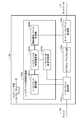
- FIG. 2 is a functional block diagram showing a configuration of a computer side I / O bus-network bridge disclosed in FIG. 1.
- FIG. 2 is a functional block diagram showing a configuration of an enclosure side I / O bus-network bridge disclosed in FIG. 1.
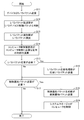
- movement of the network system disclosed in FIG. It is a flowchart which shows operation
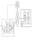
- FIG. 7 is a functional block diagram showing a configuration of a computer side I / O bus-network bridge disclosed in FIG. 6.
- FIGS. 1 to 3 are diagrams for explaining the configuration of the network expansion system according to the present invention
- FIGS. 4 to 5 are diagrams for explaining the operation thereof.
- the network expansion system (network system) according to the first embodiment of the present invention includes two computers 1a and 1b connected via a network 2, a system manager 3, and an I / O device enclosure. 4.
- the computer 1a includes a CPU 11a that operates a program, a memory 13a that stores programs and data, and a computer-side I / O bus-network bridge 14a that encapsulates I / O packets into network packets and transmits / receives them to / from the network 2. And a bridge 12a that connects the CPU 11a, the memory 13a, and the computer side I / O bus-network bridge 14a to each other.
- the bridge 12a and the computer side I / O bus-network bridge 14a are connected by an I / O bus.
- the configuration of the computer 1b is the same as the configuration of the computer 1a described above, and includes the same configurations 11b to 14b as the above-described configurations 11a to 14a. Therefore, detailed description of each of the configurations 11b to 14b is omitted.
- a case where two computers 1a and 1b are installed will be described.
- the number of computers is not limited, and three or more computers are installed. Also good.
- the I / O device enclosure 4 (device) includes an enclosure-side I / O bus-network bridge 41 that encapsulates an I / O packet into a network packet and transmits / receives data to / from the network 2, and an I / O device 42.
- I have.
- the enclosure side I / O bus-network bridge 41 and the I / O device 42 are connected by an I / O bus. Accordingly, the I / O device enclosure 4 including the I / O device 42 connected by the I / O bus and the enclosure side I / O bus-network bridge 41 constitutes an integral device.
- examples of the I / O device 42 include a network interface conforming to PCI Express (PCIe), and a combination of a storage controller and a hard disk. Accordingly, as described later, the I / O packet transmitted / received between the computers 1a and 1b and the I / O device 42 is an I / O packet conforming to PCI Express.
- PCIe PCI Express
- the above-described I / O device 42 is assigned to the computer 1a, and hereinafter, the computer-side I / O bus-network bridge 14a included in the computer 1a,
- the configuration of the enclosure side I / O bus-network bridge 41 included in the O device enclosure 4 will be described in detail. Since the configuration of the computer 1b is the same as that of the computer 1a, the computer side I / O bus-network bridge 14b included in the computer 1b has the same configuration as that included in the computer 1a.
- the computer-side I / O bus-network bridge 14a (bridge) includes an I / O packet transfer unit 141a, an I / O device control processing unit 142a, a capsule / decapsulation unit 143a, a network A packet transfer unit 144a.
- the I / O packet is transmitted from the computer 1a to the I / O device 42, the I / O packet issued by the bridge 12a is received by the I / O packet transfer unit 141a (data determination unit), and the I / O packet is received.
- the I / O packet transfer unit 141a If it is determined that the I / O packet received by the O packet transfer unit 141a is a transfer packet (transmission / reception data) to the I / O device 42, the I / O packet is transferred to the capsule / decapsulation unit 143a.
- the I / O packet issued by the bridge 12a determines whether to control a transfer packet (transmission / reception data) to be transmitted to the I / O device 42 and an I / O device 42 described later, that is, a system state.
- the I / O packet transfer unit 141a sends an I / O packet identification unit 1421a included in the I / O device control processing unit 142a described later. hand over.
- the I / O packet transfer unit 141a determines that the received I / O packet is a transfer packet or an I / O device control packet by the following method, for example.
- the computer side I / O bus-network bridge 14a is mapped to the memory space of the computer 1a, and a packet addressed to a specific memory of the computer side I / O bus-network bridge 14a is determined as an I / O device control packet.
- Others are determined to be transfer packets.
- it is determined whether the packet is an I / O device control packet or a transfer packet according to a predetermined value of a specific area of the I / O packet.
- the method for identifying the I / O packet is not limited to the method described above.
- the capsule decapsulation unit 143a (capsule decapsulation means) encapsulates the I / O packet (transfer packet) transferred from the I / O packet transfer unit 141a into a network packet and passes it to the network packet transfer unit 144a. . Then, the network packet transfer unit 144a transmits the network packet to the network 2 with the network address of the enclosure side I / O bus-network bridge 41 as a destination.
- the network 2 transmits a network packet in which an I / O packet is encapsulated to a target node.
- the network packet from the computer 1 a is transmitted to the enclosure side I / O bus-network bridge 41 of the I / O device enclosure 4.
- the network 2 conversely transmits the network packet from the enclosure side I / O bus-network bridge 41 of the I / O device enclosure 4 to the computer side I / O bus-network bridge 14a of the computer 1a.
- the network packet transfer unit 144a, the capsule / decapsulation unit 143a, and the I / O packet transfer unit 141a described above each encapsulate an I / O packet (transfer packet) transmitted from the I / O device 42 via the network 2.
- the reverse processing to the above is performed on the converted network packet. That is, when the network packet transfer unit 144a receives a network packet from the network 2, the capsule / decapsulation unit 143a performs decapsulation for releasing the encapsulation of the network packet. Then, the I / O packet transfer unit 141a passes the decapsulated I / O packet (transfer packet) to the CPU 11a and the memory 13a via the bridge 12a.
- the I / O device control processing unit 142a included in the computer-side I / O bus-network bridge 14a includes an I / O packet identification unit 1421a that identifies a received I / O packet, and a reception unit.
- I / O device control arithmetic unit 1422a that performs I / O control processing according to the I / O packet that has been performed, and an I / O packet that creates and transmits a response packet of the I / O packet received from the program operating on the computer 1a
- a response processing unit 1423a and a control notification packet generation unit 1424a that performs an I / O control process according to the calculation result of the received I / O packet are provided.
- the I / O packet identification unit 1421a (control content identification unit) issues an I / O device control packet (control auxiliary data) issued to determine whether or not the CPU 11a controls the system state.
- the I / O packet (I / O device control packet) determined to be) is received.
- the I / O packet identification unit identifies the type of control of the I / O device indicated by the received I / O packet, and notifies the I / O device control calculation unit 1422a.
- the I / O device control calculation unit 1422a performs an operation necessary for controlling the I / O device 42 by using the received I / O device control packet (control auxiliary data). An operation is performed to determine whether or not.
- the I / O device control calculation unit 1422a notifies the I / O packet response processing unit 1423a when a response to the received I / O packet is required.
- the I / O packet response processing unit 1423a (response data transmission unit) receives the notification of the calculation result from the I / O device control calculation unit 1422a, and sends the response I / O packet to the I / O packet transfer unit. It transmits to the program which operate
- the I / O device control operation unit 1422a performs an operation necessary for controlling the I / O device 42 based on the I / O device control packet (control auxiliary data) issued from the computer 1a. If it is determined that the I / O device 42 needs to be controlled as a result of the calculation to determine whether or not, the control notification packet generator 1424a is notified of this.
- the control notification packet generation unit 1424a (control data generation unit) generates a control notification packet that is information for controlling the state of the system, that is, the state of the I / O device 42, and sends the control notification packet to the system manager 3 To the network packet transfer unit 144a.
- the system manager 3 receives a control notification packet from the computer-side I / O bus-network bridge 14a and controls the I / O device 42.
- the I / O device 42 is controlled by transmitting a control notification packet from the system manager 3 to the enclosure-side I / O bus-network bridge 41.
- control of the I / O device 42 includes, for example, processing for switching the assignment of the I / O device 42 from the computer 1a to 1b, resetting the I / O device 42, and changing the operation mode of the I / O device 42. ,and so on.
- control contents of the I / O device 42 are not limited to those described above.
- the enclosure-side I / O bus-network bridge 41 includes a network packet transfer unit 411 that transfers network packets, a computer control processing unit 412 that controls the computer 1a, and encapsulation and decapsulation of I / O packets into network packets.
- the computer control processing unit 412 further includes an I / O packet identification unit 1421 for identifying the received I / O packet, and computer control for determining whether to perform computer control processing according to the received I / O packet.
- the calculation unit 4122, the I / O packet response processing unit 4123 that generates and transmits the response packet of the received I / O packet to the I / O device 42, and the network packet that notifies the control of the computer 1a are generated and transmitted.
- a control notification packet generator 4124 a control notification packet generator 4124.
- the I / O packet transfer unit 414 receives the I / O packet issued by the I / O device 42. If the I / O packet transfer unit 414 determines that the I / O packet transfer unit 414 is a transfer depacket (transmission / reception data) to the computer 1 a, the I / O packet is transferred to the capsule decapsulation unit 413.
- the I / O packet issued by the I / O device 42 is issued in order to determine whether or not to control the transfer packet (transmission / reception data) transmitted to the computer 1a and the state of the computer 1a, as described above.
- Computer control packet (control auxiliary data). Therefore, the I / O packet transfer unit 414 passes the received I / O packet to the capsule / decapsulation unit 413 when the received I / O packet is a transfer packet.
- the I / O packet transfer unit 414 passes it to the I / O packet 4124.
- the method for determining whether the I / O packet is a transfer packet or a computer control packet in the I / O packet transfer unit 414 is the same as described above, or the data in the I / O packet is changed. This can be done in various ways, for example.
- the capsule / decapsulation unit 413 (capsule / decapsulation means) encapsulates the I / O packet (transfer packet) transferred from the I / O packet transfer unit 414 into a network packet and passes it to the network packet transfer unit 411. . Then, the network packet transfer unit 411 transmits the network packet to the network 2 with the network address of the computer side I / O bus-network bridge 14a as the destination.
- the network packet transfer unit 411, the capsule / decapsulation unit 413, and the I / O packet transfer unit 414 described above perform processing opposite to that described above.
- the network packet transfer unit 411 receives a network packet from the network 2
- the capsule / decapsulation unit 413 performs decapsulation to release the encapsulation of the network packet.
- the I / O packet transfer unit 414 passes the decapsulated I / O packet (transfer packet) to the I / O device 42.
- the I / O packet identification unit 4121 (control content identification unit) issued by the I / O packet transfer unit 414 to determine whether to control the system state as described above. An I / O packet determined to be a packet (control auxiliary data) is received. Then, the I / O packet identification unit 4121 identifies the type of control of the I / O device indicated by the received I / O packet, and notifies the computer control calculation unit 4122 of it.
- the I / O device control operation unit 4122 uses the received computer control packet (control auxiliary data) to perform an operation for determining whether or not to perform an operation necessary for control of the computer 1a. Do.
- the computer control operation unit 4122 notifies the I / O packet response processing unit 4123 when a response to the received I / O packet is required.
- the I / O packet response processing unit 4123 receives the notification of the calculation result from the computer control calculation unit 4122 as described above, and sends the response I / O packet via the I / O packet transfer unit 414. To send.
- the computer control calculation unit 4122 calculates a determination as to whether or not an operation necessary for control of the computer 1a is necessary based on a computer control packet (control auxiliary data) issued from the I / O device 42. If it is determined that control of the computer 1a is necessary, the control notification packet generator 4121 is notified of this.
- the control notification packet generation unit 4121 (control data generation unit) generates a control notification packet which is information for controlling the state of the system, that is, the state of the computer 1a, and sends it to the system manager 3 via the network packet transfer unit 411. To send.
- the system manager 3 receives the control notification packet from the enclosure side I / O bus-network bridge 41 and controls the computer 1a.
- the control of the computer 1a includes, for example, power stop and restart of the computer 1a, but is not limited thereto.
- a transfer packet which is an I / O packet transmitted / received between the computer 1a and the I / O device 42, is encapsulated and transmitted / received as described above, but the description of this operation is omitted.
- the bridge 12a of the computer 1a issues an I / O packet for controlling the I / O device 42 under the control of a program operating on the CPU 11a (step S1).
- the I / O packet transfer unit 141a determines that the received I / O packet is an I / O device control packet
- the I / O packet transfer unit 141a transfers the I / O packet transfer unit 141a to the I / O packet identification unit 1421a (step S2).
- the I / O packet transfer unit 141a determines, for example, a packet addressed to a specific memory of the computer-side I / O bus-network bridge 14a as an I / O device control packet, or a specific area of the I / O packet.
- the I / O device control packet is determined based on the value.
- the I / O packet identification unit 1421a identifies the type of control of the I / O device 42 indicated by the received I / O packet (step S3), and notifies the I / O device control calculation unit 1422a. .
- the I / O device control operation unit 1422a performs an operation for determining whether or not to perform an operation necessary for controlling the I / O device 42 (step S4).
- the I / O packet response processing unit 1423a is notified.
- the I / O packet response processing unit 1423a transmits a response I / O packet to the program operating on the CPU 11a via the I / O packet transfer unit 141a (step S6).
- step S7 when the I / O device control operation unit 1422a needs to transmit a control notification packet to the system manager 3 for controlling the I / O device 42 as a result of the operation in step S4 described above (step S7). Yes), this is notified to the control notification packet generator 1424a. Then, the control notification packet generation unit 1424a transmits the control notification packet to the system manager 3 via the network packet transfer unit 144a (step S8).
- the system manager 3 receives the control notification packet and controls the I / O device 42 (step S9).
- the I / O device 42 is controlled by transmitting a control packet from the system manager 3 to the enclosure-side I / O bus-network bridge 41.
- a transfer packet which is an I / O packet transmitted / received between the I / O device 42 and the computer 1a, is encapsulated and transmitted / received as described above, but the description of this operation is omitted.
- the I / O device 42 issues an I / O packet for controlling the computer 1a by an input from a keyboard or the like (step S11). Then, the I / O packet transfer unit 414 determines that the received I / O packet is a computer control packet, and transfers it to the I / O packet identification unit 4124 (step S12).
- the I / O packet transfer unit 4124 for example, the enclosure side I / O bus-network bridge 41 is mapped to the memory space of the computer 1a, and the packet addressed to the memory is identified as a computer control packet, It is identified as a computer control packet according to the value of a specific area of a defined I / O packet.
- the I / O packet identification unit 4124 identifies the type of control of the computer 1a indicated by the received I / O packet (step S13), and notifies the computer control arithmetic unit 4122 of it.
- the computer control operation unit 4122 performs an operation for determining an operation necessary for controlling the computer 1a (step S14).
- the I / O packet response processing unit 4123 is notified.
- the I / O packet response processing unit 4123 transmits a response I / O packet to the I / O device 42 via the I / O packet transfer unit 414 (step S16).
- step S14 determines whether the control notification packet needs to be transmitted to the system manager 3 for the control of the computer 1a (Yes in step S17).
- the computer control calculation unit 4122 The packet generation unit 4121 is notified. Then, the control notification packet generation unit 4121 transmits a control notification packet to the system manager 3 via the network packet transfer unit 411 (step S18).
- the system manager 3 receives the control notification packet and controls the computer 1a (step S19).
- the computer 1a is controlled by transmitting a control packet from the system manager 3 to the computer-side I / O bus-network bridge 14a or by connecting a computer 1a and the system manager 3 in a separate system (not shown). Do through.
- the number of I / O devices 42 is one has been described.
- the number of I / O devices held by the system is not limited to the above-described number.
- an I / O packet defined as a control packet in advance is received by the I / O bus-network bridge, and is not encapsulated and is sent to the system manager by a computer or I / O device. It is sent as a network packet to notify the control of The system manager 3 controls the computer and the I / O device by receiving this packet.
- functions such as stopping and restarting a computer that are not defined on the I / O bus and changing the assignment of the I / O device to the computer can be realized using communication via the I / O bus. .
- the network expansion system is similar to the first embodiment described above in that two computers 5a and 5b, an I / O device enclosure 6, and a system manager 3 are connected via a network. And are connected.
- Each of the computers 5a and 5b has the same configuration 51a to 54a and 51b to 54b as the computer in the first embodiment.
- the system manager 3 in this embodiment has the same configuration as that described in the first embodiment.
- the I / O device enclosure 6 in the present embodiment includes an enclosure side I / O bus-network bridge as in the first embodiment, and also includes a disk controller 62 and the disk controller 62 as the I / O device 42. And a hard disk 63 controlled by the computer.
- FIG. 7 shows a detailed configuration of the computer-side I / O bus-network bridge 54a included in the computer 5a.
- the computer side I / O bus-network bridge 54a includes an I / O packet transfer unit 541a, an I / O device control processing unit 542a, a capsule / decapsulation unit 543a, and a network packet.
- the I / O device control processing unit 542a includes an I / O packet identification unit 5421a, a storage device control calculation unit 5422a, and a control notification packet generation unit 5424a.
- the storage device control calculation unit 5422a has the same function as the I / O device control calculation unit 1422 in the first embodiment.
- the network system configured as described above operates as follows. First, a set of the disk controller 62 and the hard disk 63 is assigned to the computer 5a. The program that operates on the CPU 11a operates while writing data to be taken over to the computer 5b, which is a standby system, when a failure occurs in the computer 5a.
- the I / O device control program operating on the CPU 11a transmits a life / death monitoring I / O packet (control auxiliary data) to the computer-side I / O bus-network bridge 54a at regular intervals. Then, the computer side I / O bus-network bridge 54a determines that the I / O packet received by the I / O packet transfer unit 541a is an I / O device control packet, and the I / O packet identification unit 5421a. Forward to. The I / O packet identification unit 5421a identifies that the received I / O packet is a life / death monitoring packet, and notifies the storage device control calculation unit 5422a.
- the storage device control arithmetic unit 5422a drives a timer for I / O device switching control, and resets the timer upon receipt of a life / death monitoring packet.
- the timer driven by the storage device control calculation unit 5422a times out and the control notification packet for switching the I / O device allocation switching is transmitted.
- Notification packet generation unit 5424a is notified.
- the control notification packet generator 5424a notifies the system manager 3 to change the assignment of the set of the disco controller 62 and the hard disk 63 from the computer 5a to the computer 5b by this notification.
- the system manager 3 switches the assignment of the I / O device by transmitting a control packet to the enclosure side I / O bus-network bridge 41. By this operation, the data stored in the hard disk 63 is taken over from the computer 5a in which the failure has occurred in the software to the standby computer 5b.
- the system in the present embodiment has basically the same configuration as that of the first embodiment described above.
- a keyboard 72 is held as a specific example of the I / O device 42 of the first embodiment.
- the system manager 3 and the computer 1 a are connected by a management network 8.
- the detailed configuration of the enclosure side I / O bus-network bridge 71 is as shown in FIG.
- the system in this embodiment operates as follows.
- a case is considered in which the computer 1a is stopped or restarted by a predetermined keyboard 72 input.
- the keyboard 72 transmits an I / O packet to the enclosure-side I / O bus-network bridge 71. Then, the I / O packet transfer unit 414 determines that the received I / O packet is a computer control packet, and transfers the I / O packet to the I / O packet identification unit 4124. The I / O packet identification unit 4124 identifies whether the received I / O packet indicates the stop or restart of the computer 1 a and notifies the computer control arithmetic unit 4122.
- the computer control operation unit 4122 notifies the system manager 3 to transmit a control notification packet corresponding to the control identified by the control notification packet generation unit 4121.
- the control notification packet generation unit 4121 creates a control notification packet and transmits it to the system manager 3.
- the system manager 3 receives the control notification packet, and stops or restarts the computer 5 a instructed using the management network 8.
- the stop and restart of the computer 5a have been described above, but other operations of the computer 5a are possible.
- the control of the computer 5 a by the system manager 3 may be performed via the network 2.
- a computer and a device connected via a network so that data can be transmitted and received between each other, and a system management device for controlling the state of a system configured by the computer and the device are provided via the network.
- the computer and the device each include a bridge that encapsulates transmission / reception data to be transmitted / received to / from each other and transmits / receives to / from each other via a network, Each of the bridges generates control data for controlling the state of the system based on auxiliary control data used for controlling the state of the system issued from the computer or the device to generate the system via a network.
- the system management device includes system control means for controlling the state of the system according to the received control data.
- Network system
- Each bridge includes capsule decapsulation means for encapsulating the transmission / reception data to be transmitted and decapsulating the received transmission / reception data,
- the control data transmission means included in each bridge transmits the control data to the system management apparatus without being encapsulated by the capsule decapsulation means.
- Each bridge includes data determination means for determining whether data transmitted from the computer or the device is the transmission / reception data or the control auxiliary data.
- the data discriminating unit passes the transmission / reception data to the capsule / decapsulation unit, and passes the control auxiliary data to the control data transmission unit.
- control data transmitting means controls the control content identified by the control content identifying unit based on the control auxiliary data and the control content identifying unit for identifying the control content of the system corresponding to the control auxiliary data
- a control determination unit that determines whether or not
- a control data generation unit that generates the control data according to the determination by the control determination unit and transmits the control data to the system management device, Network system.
- control data transmission means includes a response data transmission unit that transmits response data to the computer or the device that is the source of the control auxiliary data in accordance with the determination by the control determination unit.
- Network system
- the control data transmission means generates the control data for controlling assignment of the computer to the device based on the control auxiliary data issued from the computer.
- Network system The control data transmission means generates the control data for controlling assignment of the computer to the device based on the control auxiliary data issued from the computer.
- control determination unit included in the control data transmission means determines whether or not the control auxiliary data issued from the computer has been received for a preset time
- the control data generation unit included in the control data transmission unit is configured to change the assignment to the device to another computer when the control auxiliary data issued from the computer is not received for a preset time or more. Generating the control data for controlling the state of Network system.
- the control data transmission means generates the control data for controlling stop or restart of the computer based on the control auxiliary data issued from the device. Network system.
- the network system according to any one of appendices 1 to 8,
- the device is a PCI Express compatible device, and the data generated from the computer or the device is an I / O packet conforming to PCI Express. Network system.
- a computer that can send and receive data to and from devices connected via a network, A bridge for encapsulating transmission / reception data to be transmitted / received to / from the device and transmitting / receiving to / from the device via a network;
- the bridge generates control data for controlling the state of a system configured by being connected to the device via a network based on control auxiliary data issued by the computer, and the control data is generated in the system.
- Control data transmission means for transmitting to the system management device for controlling the state of the network via the network, Computer.
- the computer according to appendix 10, wherein The bridge includes capsule decapsulation means for encapsulating the transmission / reception data to be transmitted to the device and decapsulating the transmission / reception data received from the device,
- the control data transmission means included in the bridge transmits the control data to the system management apparatus without being encapsulated by the capsule / decapsulation means.
- the control data transmission means included in the bridge transmits the control data to the system management apparatus without being encapsulated by the capsule / decapsulation means.
- a bridge installed on a computer that can send and receive data to and from devices connected via a network. Encapsulating transmission / reception data transmitted / received to / from the device and transmitting / receiving data via the network, Based on the control auxiliary data issued by its own computer, it generates control data for controlling the state of the system configured by being connected to the device via the network, and controls the state of the system using the control data. Send to the system management device over the network, Network system control method.
- Appendix 15 A network system control method according to appendix 14, wherein The bridge encapsulates the transmission / reception data transmitted to the device, releases the encapsulation of the transmission / reception data received from the device, and transmits the control data to the system management apparatus without encapsulating the control data. , Network system control method.
- a device capable of sending and receiving data to and from a computer connected via a network, Comprising a bridge for encapsulating transmission / reception data transmitted / received to / from the computer and transmitting / receiving data via a network;
- the bridge generates control data for controlling a state of a system configured by being connected to the computer via a network based on control auxiliary data issued by the device, and the control data is generated in the system.
- Control data transmission means for transmitting to the system management device for controlling the state of the network via the network, device.
- the device (Appendix 17) The device according to appendix 16, wherein The bridge includes capsule decapsulation means for encapsulating the transmission / reception data to be transmitted to the computer and for decapsulating the transmission / reception data received from the computer,
- the control data transmission means included in the bridge transmits the control data to the system management apparatus without being encapsulated by the capsule / decapsulation means. device.
- a computer and a device connected via a network so that data can be transmitted and received between each other, and a system management device for controlling the state of a system configured by the computer and the device are provided via the network
- a network system control method in a network system Each bridge provided in each of the computer and the device encapsulates transmission / reception data to be transmitted / received to / from each other via the network, and controls the state of the system issued from the computer or the device.
- the system management device controls the state of the system according to the received control data; Network control method.
- the program is stored in a storage device or recorded on a computer-readable recording medium.
- the recording medium is a portable medium such as a flexible disk, an optical disk, a magneto-optical disk, and a semiconductor memory.
Landscapes
- Engineering & Computer Science (AREA)
- Theoretical Computer Science (AREA)
- Computer Networks & Wireless Communication (AREA)
- Signal Processing (AREA)
- Physics & Mathematics (AREA)
- General Engineering & Computer Science (AREA)
- General Physics & Mathematics (AREA)
- Environmental & Geological Engineering (AREA)
- Small-Scale Networks (AREA)
- Computer And Data Communications (AREA)
Abstract
Description
相互にデータの送受信が可能なようネットワークを介して接続されたコンピュータとデバイスとを備えると共に、前記コンピュータと前記デバイスとにより構成されたシステムの状態を制御するシステム管理装置をネットワークを介して備え、
前記コンピュータと前記デバイスとは、相互に送受信する送受信データをカプセル化してネットワークを介して相互に送受信するブリッジをそれぞれ備えると共に、
前記各ブリッジは、前記コンピュータあるいは前記デバイスから発行される前記システムの状態を制御するために用いられる制御補助データに基づいて前記システムの状態を制御する制御データを生成してネットワークを介して前記システム管理装置に送信する制御データ送信手段を備え、
前記システム管理装置は、受信した前記制御データに従って前記システムの状態を制御するシステム制御手段を備えた、
という構成を取る。
ネットワークを介して接続されたデバイスと相互にデータの送受信が可能なコンピュータであって、
前記デバイスと相互に送受信する送受信データをカプセル化してネットワークを介して相互に送受信するブリッジを備え、
前記ブリッジは、自コンピュータが発行した制御補助データに基づいて、前記デバイスとネットワークを介して接続されることにより構成されたシステムの状態を制御する制御データを生成して、当該制御データを前記システムの状態を制御するシステム管理装置にネットワークを介して送信する制御データ送信手段を備えた、
という構成を取る。
ネットワークを介して接続されたデバイスと相互にデータの送受信が可能なコンピュータに、
前記デバイスと相互に送受信する送受信データをカプセル化してネットワークを介して相互に送受信するブリッジを実現させると共に、
前記ブリッジは、自コンピュータが発行した制御補助データに基づいて、前記デバイスとネットワークを介して接続されることにより構成されたシステムの状態を制御する制御データを生成して、当該制御データを前記システムの状態を制御するシステム管理装置にネットワークを介して送信する制御データ送信手段を備えた、
ことを実現させるためのプログラムである。
ネットワークを介して接続されたデバイスと相互にデータの送受信が可能なコンピュータに装備されたブリッジが、
前記デバイスと相互に送受信する送受信データをカプセル化してネットワークを介して相互に送受信すると共に、
自コンピュータが発行した制御補助データに基づいて、前記デバイスとネットワークを介して接続されることにより構成されたシステムの状態を制御する制御データを生成して、当該制御データを前記システムの状態を制御するシステム管理装置にネットワークを介して送信する、
という構成を取る。
ネットワークを介して接続されたコンピュータと相互にデータの送受信が可能なデバイスであって、
前記コンピュータと相互に送受信する送受信データをカプセル化してネットワークを介して相互に送受信するブリッジを備え、
前記ブリッジは、自デバイスが発行した制御補助データに基づいて、前記コンピュータとネットワークを介して接続されることにより構成されたシステムの状態を制御する制御データを生成して、当該制御データを前記システムの状態を制御するシステム管理装置にネットワークを介して送信する制御データ送信手段を備えた、
という構成を取る。
ネットワークを介して接続されたコンピュータと相互にデータの送受信が可能なデバイスに、
前記コンピュータと相互に送受信する送受信データをカプセル化してネットワークを介して相互に送受信するブリッジを実現させると共に、
前記ブリッジは、自デバイスが発行した制御補助データに基づいて、前記コンピュータとネットワークを介して接続されることにより構成されたシステムの状態を制御する制御データを生成して、当該制御データを前記システムの状態を制御するシステム管理装置にネットワークを介して送信する制御データ送信手段を備えた、
ことを実現させるためのプログラムである。
ネットワークを介して接続されたコンピュータと相互にデータの送受信が可能なデバイスに装備されたブリッジが、
前記コンピュータと相互に送受信する送受信データをカプセル化してネットワークを介して相互に送受信すると共に、
自デバイスが発行した制御補助データに基づいて、前記コンピュータとネットワークを介して接続されることにより構成されたシステムの状態を制御する制御データを生成して、当該制御データを前記システムの状態を制御するシステム管理装置にネットワークを介して送信する、
という構成を取る。
相互にデータの送受信が可能なようネットワークを介して接続されたコンピュータとデバイスとを備えると共に、前記コンピュータと前記デバイスとにより構成されたシステムの状態を制御するシステム管理装置をネットワークを介して備えたネットワークシステムにおけるネットワークシステム制御方法であって、
前記コンピュータと前記デバイスとにそれぞれ装備された各ブリッジが、相互に送受信する送受信データをカプセル化してネットワークを介して相互に送受信すると共に、前記コンピュータあるいは前記デバイスから発行される前記システムの状態を制御するために用いられる制御補助データに基づいて前記システムの状態を制御する制御データを生成してネットワークを介して前記システム管理装置に送信し、
前記システム管理装置が、受信した前記制御データに従って前記システムの状態を制御する、
という構成を取る。
図1に示すように、本発明の実施形態1におけるネットワーク拡張システム(ネットワークシステム)は、ネットワーク2を介して接続された2台のコンピュータ1a,1bと、システムマネージャ3と、I/Oデバイスエンクロージャ4と、を備えて構成されている。
次に、図1,2と図4のフローチャートを参照して、コンピュータ1aからI/Oデバイス42を制御する動作を説明する。なお、コンピュータ1aとI/Oデバイス42との間で送受信されるI/Oパケットである転送パケットは、上述したようにカプセル化されて送受信されるが、かかる動作の説明は省略する。
次に、本発明の第2の実施形態を、図6乃至図7を参照して説明する。なお、本実施形態は、上述した実施形態1の具体的な一例を示すものである。
次に、本発明の第3の実施形態を、図8を参照して説明する。なお、本実施形態は、上述した実施形態1の具体的な一例を示すものである。
上記実施形態の一部又は全部は、以下の付記のようにも記載されうる。以下、本発明におけるネットワークシステムの概略を説明する。但し、本発明は、以下の構成に限定されない。
相互にデータの送受信が可能なようネットワークを介して接続されたコンピュータとデバイスとを備えると共に、前記コンピュータと前記デバイスとにより構成されたシステムの状態を制御するシステム管理装置をネットワークを介して備え、
前記コンピュータと前記デバイスとは、相互に送受信する送受信データをカプセル化してネットワークを介して相互に送受信するブリッジをそれぞれ備えると共に、
前記各ブリッジは、前記コンピュータあるいは前記デバイスから発行される前記システムの状態を制御するために用いられる制御補助データに基づいて前記システムの状態を制御する制御データを生成してネットワークを介して前記システム管理装置に送信する制御データ送信手段を備え、
前記システム管理装置は、受信した前記制御データに従って前記システムの状態を制御するシステム制御手段を備えた、
ネットワークシステム。
付記1に記載のネットワークシステムであって、
前記各ブリッジは、送信する前記送受信データをカプセル化すると共に受信した前記送受信データのカプセル化を解除するカプセル・デカプセル手段を備え、
前記各ブリッジが有する前記制御データ送信手段は、前記制御データを前記カプセル・デカプセル手段にてカプセル化せずに前記システム管理装置に送信する、
ネットワークシステム。
付記2に記載のネットワークシステムであって、
前記各ブリッジは、前記コンピュータあるいは前記デバイスから発せられたデータが前記送受信データであるか前記制御補助データであるかを判別するデータ判別手段を備え、
前記データ判別手段は、前記送受信データを前記カプセル・デカプセル手段に渡し、前記制御補助データを前記制御データ送信手段に渡す、
ネットワークシステム。
付記3に記載のネットワークシステムであって、
前記制御データ送信手段は、前記制御補助データに対応する前記システムの制御内容を識別する制御内容識別部と、前記制御補助データに基づいて前記制御内容識別部にて識別した制御内容の制御を行うか否かを判断する制御判断部と、前記制御判断部による判断に応じて前記制御データを生成して前記システム管理装置に送信する制御データ生成部と、を備えた、
ネットワークシステム。
付記4に記載のネットワークシステムであって、
前記制御データ送信手段は、前記前記制御判断部による判断に応じて、前記制御補助データの発行元となる前記コンピュータあるいは前記デバイスに対して応答データを送信する応答データ送信部を備えた、
ネットワークシステム。
付記1乃至5のいずれかに記載のネットワークシステムであって、
前記制御データ送信手段は、前記コンピュータから発行された前記制御補助データに基づいて前記デバイスに対する前記コンピュータの割り当てを制御する前記制御データを生成する、
ネットワークシステム。
付記4に記載のネットワークシステムであって、
前記制御データ送信手段が有する前記制御判断部は、前記コンピュータから発行された前記制御補助データを予め設定された時間以上受信していないかどうかを判断し、
前記制御データ送信手段が有する前記制御データ生成部は、前記コンピュータから発行された前記制御補助データを予め設定された時間以上受信しない場合に、前記デバイスに対する割り当てを他のコンピュータに変更するよう前記システムの状態を制御する前記制御データを生成する、
ネットワークシステム。
付記1乃至5のいずれかに記載のネットワークシステムであって、
前記制御データ送信手段は、前記デバイスから発行された前記制御補助データに基づいて前記コンピュータの停止あるいは再起動を制御する前記制御データを生成する、
ネットワークシステム。
付記1乃至8のいずれかに記載のネットワークシステムであって、
前記デバイスは、PCI Express対応機器であり、前記コンピュータあるいは前記デバイスから発せられたデータは、PCI Expressに準拠するI/Oパケットである、
ネットワークシステム。
ネットワークを介して接続されたデバイスと相互にデータの送受信が可能なコンピュータであって、
前記デバイスと相互に送受信する送受信データをカプセル化してネットワークを介して相互に送受信するブリッジを備え、
前記ブリッジは、自コンピュータが発行した制御補助データに基づいて、前記デバイスとネットワークを介して接続されることにより構成されたシステムの状態を制御する制御データを生成して、当該制御データを前記システムの状態を制御するシステム管理装置にネットワークを介して送信する制御データ送信手段を備えた、
コンピュータ。
付記10に記載のコンピュータであって、
前記ブリッジは、前記デバイスに対して送信する前記送受信データをカプセル化すると共に前記デバイスから受信した前記送受信データのカプセル化を解除するカプセル・デカプセル手段を備え、
前記ブリッジが有する前記制御データ送信手段は、前記制御データを前記カプセル・デカプセル手段にてカプセル化せずに前記システム管理装置に送信する、
コンピュータ。
ネットワークを介して接続されたデバイスと相互にデータの送受信が可能なコンピュータに、
前記デバイスと相互に送受信する送受信データをカプセル化してネットワークを介して相互に送受信するブリッジを実現させると共に、
前記ブリッジは、自コンピュータが発行した制御補助データに基づいて、前記デバイスとネットワークを介して接続されることにより構成されたシステムの状態を制御する制御データを生成して、当該制御データを前記システムの状態を制御するシステム管理装置にネットワークを介して送信する制御データ送信手段を備えた、
ことを実現させるためのプログラム。
付記11に記載のプログラムであって、
前記ブリッジは、前記デバイスに対して送信する前記送受信データをカプセル化すると共に前記デバイスから受信した前記送受信データのカプセル化を解除するカプセル・デカプセル手段を備えると共に、
前記ブリッジが有する前記制御データ送信手段は、前記制御データを前記カプセル・デカプセル手段にてカプセル化せずに前記システム管理装置に送信する、
ことを実現させるためのプログラム。
ネットワークを介して接続されたデバイスと相互にデータの送受信が可能なコンピュータに装備されたブリッジが、
前記デバイスと相互に送受信する送受信データをカプセル化してネットワークを介して相互に送受信すると共に、
自コンピュータが発行した制御補助データに基づいて、前記デバイスとネットワークを介して接続されることにより構成されたシステムの状態を制御する制御データを生成して、当該制御データを前記システムの状態を制御するシステム管理装置にネットワークを介して送信する、
ネットワークシステム制御方法。
付記14に記載のネットワークシステム制御方法であって、
前記ブリッジが、前記デバイスに対して送信する前記送受信データをカプセル化し、前記デバイスから受信した前記送受信データのカプセル化を解除すると共に、前記制御データをカプセル化せずに前記システム管理装置に送信する、
ネットワークシステム制御方法。
ネットワークを介して接続されたコンピュータと相互にデータの送受信が可能なデバイスであって、
前記コンピュータと相互に送受信する送受信データをカプセル化してネットワークを介して相互に送受信するブリッジを備え、
前記ブリッジは、自デバイスが発行した制御補助データに基づいて、前記コンピュータとネットワークを介して接続されることにより構成されたシステムの状態を制御する制御データを生成して、当該制御データを前記システムの状態を制御するシステム管理装置にネットワークを介して送信する制御データ送信手段を備えた、
デバイス。
付記16に記載のデバイスであって、
前記ブリッジは、前記コンピュータに対して送信する前記送受信データをカプセル化すると共に前記コンピュータから受信した前記送受信データのカプセル化を解除するカプセル・デカプセル手段を備え、
前記ブリッジが有する前記制御データ送信手段は、前記制御データを前記カプセル・デカプセル手段にてカプセル化せずに前記システム管理装置に送信する、
デバイス。
ネットワークを介して接続されたコンピュータと相互にデータの送受信が可能なデバイスに、
前記コンピュータと相互に送受信する送受信データをカプセル化してネットワークを介して相互に送受信するブリッジを実現させると共に、
前記ブリッジは、自デバイスが発行した制御補助データに基づいて、前記コンピュータとネットワークを介して接続されることにより構成されたシステムの状態を制御する制御データを生成して、当該制御データを前記システムの状態を制御するシステム管理装置にネットワークを介して送信する制御データ送信手段を備えた、
ことを実現させるためのプログラム。
付記18に記載のプログラムであって、
前記ブリッジは、前記コンピュータに対して送信する前記送受信データをカプセル化すると共に前記コンピュータから受信した前記送受信データのカプセル化を解除するカプセル・デカプセル手段を備え、
前記ブリッジが有する前記制御データ送信手段は、前記制御データを前記カプセル・デカプセル手段にてカプセル化せずに前記システム管理装置に送信する、
ことを実現させるためのプログラム。
ネットワークを介して接続されたコンピュータと相互にデータの送受信が可能なデバイスに装備されたブリッジが、
前記コンピュータと相互に送受信する送受信データをカプセル化してネットワークを介して相互に送受信すると共に、
自デバイスが発行した制御補助データに基づいて、前記コンピュータとネットワークを介して接続されることにより構成されたシステムの状態を制御する制御データを生成して、当該制御データを前記システムの状態を制御するシステム管理装置にネットワークを介して送信する、
ネットワークシステム制御方法。
付記20に記載のネットワークシステム制御方法であって、
前記ブリッジが、前記コンピュータに対して送信する前記送受信データをカプセル化し、前記コンピュータから受信した前記送受信データのカプセル化を解除すると共に、前記制御データをカプセル化せずに前記システム管理装置に送信する、
ネットワークシステム制御方法。
相互にデータの送受信が可能なようネットワークを介して接続されたコンピュータとデバイスとを備えると共に、前記コンピュータと前記デバイスとにより構成されたシステムの状態を制御するシステム管理装置をネットワークを介して備えたネットワークシステムにおけるネットワークシステム制御方法であって、
前記コンピュータと前記デバイスとにそれぞれ装備された各ブリッジが、相互に送受信する送受信データをカプセル化してネットワークを介して相互に送受信すると共に、前記コンピュータあるいは前記デバイスから発行される前記システムの状態を制御するために用いられる制御補助データに基づいて前記システムの状態を制御する制御データを生成してネットワークを介して前記システム管理装置に送信し、
前記システム管理装置が、受信した前記制御データに従って前記システムの状態を制御する、
ネットワーク制御方法。
付記22に記載のネットワーク制御方法であって、
前記各ブリッジが、送信する前記送受信データをカプセル化し、受信した前記送受信データのカプセル化を解除すると共に、前記制御データをカプセル化せずに前記システム管理装置に送信する、
ネットワーク制御方法。
11a,11b CPU
12a,12b ブリッジ
13a,13b メモリ
14a,14b コンピュータ側I/Oバス-ネットワークブリッジ
141a I/Oパケット転送部
142a I/Oデバイス制御処理部
1421a I/Oパケット識別部
1422a I/Oデバイス制御演算部
1423a I/Oパケット応答処理部
1424a 制御通知パケット生成部
143a カプセル・デカプセル部
144a ネットワークパケット転送部
2 ネットワーク
3 システムマネージャ
4 I/Oデバイスエンクロージャ
41 エンクロージャ側I/Oバス-ネットワークブリッジ
411 ネットワークパケット転送部
412 コンピュータ制御処理部
4121 制御通知パケット生成部
4122 コンピュータ制御演算部
4123 I/Oパケット応答処理部
4124 I/Oパケット識別部
413 カプセル・デカプセル部
414 I/Oパケット転送部
42 I/Oデバイス
5a,5b コンピュータ
51a,51b CPU
52a,52b ブリッジ
53a,53b メモリ
54a,54b コンピュータ側I/Oバス-ネットワークブリッジ
541a I/Oパケット転送部
542a I/Oデバイス制御処理部
5421a I/Oパケット識別部
5422a ストレージデバイス制御演算部
5424a 制御通知パケット生成部
543a カプセル・デカプセル部
544a ネットワークパケット転送部
6 I/Oデバイスエンクロージャ
61 エンクロージャ側I/Oバス-ネットワークブリッジ
62 ディスクコントローラ
63 ハードディスク
7 I/Oデバイスエンクロージャ
71 エンクロージャ側I/Oバス-ネットワークブリッジ
72 キーボード
8a,8b コンピュータ
81a,81b CPU
82a,82b ブリッジ
83a,83b メモリ
84a,84b コンピュータ側I/Oバス-ネットワークブリッジ
9 I/Oデバイスエンクロージャ
91 エンクロージャ側I/Oバス-ネットワークブリッジ
92 I/Oデバイス
30 システムマネージャ
Claims (11)
- 相互にデータの送受信が可能なようネットワークを介して接続されたコンピュータとデバイスとを備えると共に、前記コンピュータと前記デバイスとにより構成されたシステムの状態を制御するシステム管理装置をネットワークを介して備え、
前記コンピュータと前記デバイスとは、相互に送受信する送受信データをカプセル化してネットワークを介して相互に送受信するブリッジをそれぞれ備えると共に、
前記各ブリッジは、前記コンピュータあるいは前記デバイスから発行される前記システムの状態を制御するために用いられる制御補助データに基づいて前記システムの状態を制御する制御データを生成してネットワークを介して前記システム管理装置に送信する制御データ送信手段を備え、
前記システム管理装置は、受信した前記制御データに従って前記システムの状態を制御するシステム制御手段を備えた、
ネットワークシステム。 - 請求項1に記載のネットワークシステムであって、
前記各ブリッジは、送信する前記送受信データをカプセル化すると共に受信した前記送受信データのカプセル化を解除するカプセル・デカプセル手段を備え、
前記各ブリッジが有する前記制御データ送信手段は、前記制御データを前記カプセル・デカプセル手段にてカプセル化せずに前記システム管理装置に送信する、
ネットワークシステム。 - 請求項2に記載のネットワークシステムであって、
前記各ブリッジは、前記コンピュータあるいは前記デバイスから発せられたデータが前記送受信データであるか前記制御補助データであるかを判別するデータ判別手段を備え、
前記データ判別手段は、前記送受信データを前記カプセル・デカプセル手段に渡し、前記制御補助データを前記制御データ送信手段に渡す、
ネットワークシステム。 - 請求項3に記載のネットワークシステムであって、
前記制御データ送信手段は、前記制御補助データに対応する前記システムの制御内容を識別する制御内容識別部と、前記制御補助データに基づいて前記制御内容識別部にて識別した制御内容の制御を行うか否かを判断する制御判断部と、前記制御判断部による判断に応じて前記制御データを生成して前記システム管理装置に送信する制御データ生成部と、を備えた、
ネットワークシステム。 - 請求項4に記載のネットワークシステムであって、
前記制御データ送信手段は、前記前記制御判断部による判断に応じて、前記制御補助データの発行元となる前記コンピュータあるいは前記デバイスに対して応答データを送信する応答データ送信部を備えた、
ネットワークシステム。 - 請求項1乃至5のいずれかに記載のネットワークシステムであって、
前記制御データ送信手段は、前記コンピュータから発行された前記制御補助データに基づいて前記デバイスに対する前記コンピュータの割り当てを制御する前記制御データを生成する、
ネットワークシステム。 - 請求項4に記載のネットワークシステムであって、
前記制御データ送信手段が有する前記制御判断部は、前記コンピュータから発行された前記制御補助データを予め設定された時間以上受信していないかどうかを判断し、
前記制御データ送信手段が有する前記制御データ生成部は、前記コンピュータから発行された前記制御補助データを予め設定された時間以上受信しない場合に、前記デバイスに対する割り当てを他のコンピュータに変更するよう前記システムの状態を制御する前記制御データを生成する、
ネットワークシステム。 - 請求項1乃至5のいずれかに記載のネットワークシステムであって、
前記制御データ送信手段は、前記デバイスから発行された前記制御補助データに基づいて前記コンピュータの停止あるいは再起動を制御する前記制御データを生成する、
ネットワークシステム。 - ネットワークを介して接続されたデバイスと相互にデータの送受信が可能なコンピュータであって、
前記デバイスと相互に送受信する送受信データをカプセル化してネットワークを介して相互に送受信するブリッジを備え、
前記ブリッジは、自コンピュータが発行した制御補助データに基づいて、前記デバイスとネットワークを介して接続されることにより構成されたシステムの状態を制御する制御データを生成して、当該制御データを前記システムの状態を制御するシステム管理装置にネットワークを介して送信する制御データ送信手段を備えた、
コンピュータ。 - ネットワークを介して接続されたコンピュータと相互にデータの送受信が可能なデバイスであって、
前記コンピュータと相互に送受信する送受信データをカプセル化してネットワークを介して相互に送受信するブリッジを備え、
前記ブリッジは、自デバイスが発行した制御補助データに基づいて、前記コンピュータとネットワークを介して接続されることにより構成されたシステムの状態を制御する制御データを生成して、当該制御データを前記システムの状態を制御するシステム管理装置にネットワークを介して送信する制御データ送信手段を備えた、
デバイス。 - 相互にデータの送受信が可能なようネットワークを介して接続されたコンピュータとデバイスとを備えると共に、前記コンピュータと前記デバイスとにより構成されたシステムの状態を制御するシステム管理装置をネットワークを介して備えたネットワークシステムにおけるネットワークシステム制御方法であって、
前記コンピュータと前記デバイスとにそれぞれ装備された各ブリッジが、相互に送受信する送受信データをカプセル化してネットワークを介して相互に送受信すると共に、前記コンピュータあるいは前記デバイスから発行される前記システムの状態を制御するために用いられる制御補助データに基づいて前記システムの状態を制御する制御データを生成してネットワークを介して前記システム管理装置に送信し、
前記システム管理装置が、受信した前記制御データに従って前記システムの状態を制御する、
ネットワーク制御方法。
Priority Applications (4)
| Application Number | Priority Date | Filing Date | Title |
|---|---|---|---|
| EP12755620.7A EP2685385B1 (en) | 2011-03-09 | 2012-01-19 | Network system |
| CN201280012373XA CN103415845A (zh) | 2011-03-09 | 2012-01-19 | 网络系统 |
| US14/003,518 US9882737B2 (en) | 2011-03-09 | 2012-01-19 | Network system |
| JP2013503341A JP6036683B2 (ja) | 2011-03-09 | 2012-01-19 | ネットワークシステム |
Applications Claiming Priority (2)
| Application Number | Priority Date | Filing Date | Title |
|---|---|---|---|
| JP2011051098 | 2011-03-09 | ||
| JP2011-051098 | 2011-03-09 |
Publications (1)
| Publication Number | Publication Date |
|---|---|
| WO2012120761A1 true WO2012120761A1 (ja) | 2012-09-13 |
Family
ID=46797741
Family Applications (1)
| Application Number | Title | Priority Date | Filing Date |
|---|---|---|---|
| PCT/JP2012/000299 Ceased WO2012120761A1 (ja) | 2011-03-09 | 2012-01-19 | ネットワークシステム |
Country Status (5)
| Country | Link |
|---|---|
| US (1) | US9882737B2 (ja) |
| EP (1) | EP2685385B1 (ja) |
| JP (1) | JP6036683B2 (ja) |
| CN (1) | CN103415845A (ja) |
| WO (1) | WO2012120761A1 (ja) |
Cited By (1)
| Publication number | Priority date | Publication date | Assignee | Title |
|---|---|---|---|---|
| JP2014139748A (ja) * | 2013-01-21 | 2014-07-31 | Nec Corp | コンピュータシステム、コンピュータシステムの起動方法、及びプログラム |
Families Citing this family (5)
| Publication number | Priority date | Publication date | Assignee | Title |
|---|---|---|---|---|
| JP2584149Y2 (ja) | 1992-12-28 | 1998-10-30 | 住友電装株式会社 | 端子付き電線へのグロメット類の嵌着治具 |
| US10601653B2 (en) * | 2012-07-06 | 2020-03-24 | Cradlepoint, Inc. | Implicit traffic engineering |
| US10110417B1 (en) | 2012-07-06 | 2018-10-23 | Cradlepoint, Inc. | Private networks overlaid on cloud infrastructure |
| US11386020B1 (en) * | 2020-03-03 | 2022-07-12 | Xilinx, Inc. | Programmable device having a data processing engine (DPE) array |
| EP4231594A4 (en) * | 2020-10-19 | 2023-11-15 | Nissan Motor Co., Ltd. | RELAY DEVICE, COMMUNICATION NETWORK SYSTEM AND COMMUNICATION CONTROL METHOD |
Citations (3)
| Publication number | Priority date | Publication date | Assignee | Title |
|---|---|---|---|---|
| JP2003296154A (ja) * | 2002-04-05 | 2003-10-17 | Hitachi Ltd | ボリューム統合管理方法および統合管理システム |
| JP2005234917A (ja) * | 2004-02-20 | 2005-09-02 | Hitachi Ltd | 障害時のサーバ決定方法 |
| JP2007219873A (ja) | 2006-02-17 | 2007-08-30 | Nec Corp | スイッチ及びネットワークブリッジ装置 |
Family Cites Families (13)
| Publication number | Priority date | Publication date | Assignee | Title |
|---|---|---|---|---|
| US7593414B2 (en) * | 2003-09-04 | 2009-09-22 | At&T Intellectual Property I, L.P. | Enhanced CSU/DSU (channel service unit/data service unit) for frame relay over DSL |
| US8156296B2 (en) * | 2006-07-28 | 2012-04-10 | Dell Products L.P. | System and method for managing resets in a system using shared storage |
| WO2009025381A1 (ja) * | 2007-08-23 | 2009-02-26 | Nec Corporation | I/oシステムおよびi/o制御方法 |
| US8140279B2 (en) * | 2007-09-24 | 2012-03-20 | Budderfly Ventures, Llc | Computer based energy management |
| JP5564948B2 (ja) * | 2007-10-26 | 2014-08-06 | 日本電気株式会社 | I/o接続システムおよびi/o接続方法 |
| JP5645014B2 (ja) * | 2008-05-28 | 2014-12-24 | 日本電気株式会社 | I/o接続システム、方法及びプログラム |
| US20100332212A1 (en) * | 2008-09-19 | 2010-12-30 | Ori Finkelman | Method and apparatus for sleep and wake of computer devices |
| US8358670B2 (en) * | 2008-12-30 | 2013-01-22 | Samsung Electronics Co., Ltd. | Method and apparatus for processing packet |
| JP5281942B2 (ja) * | 2009-03-26 | 2013-09-04 | 株式会社日立製作所 | 計算機およびその障害処理方法 |
| US8199753B2 (en) * | 2009-06-05 | 2012-06-12 | Juniper Networks, Inc. | Forwarding frames in a computer network using shortest path bridging |
| US8620154B2 (en) * | 2009-07-31 | 2013-12-31 | Samsung Electronics Co., Ltd. | Methods and apparatus for fast and energy-efficient light recovery in a visible light communication (VLC) system |
| US8705542B2 (en) * | 2010-06-17 | 2014-04-22 | Telfonaktiebolaget Lm Ericsson (Publ) | L2 method for partial VLAN service migration |
| US8537816B2 (en) * | 2010-12-29 | 2013-09-17 | Avaya, Inc. | Multicast VPN support for IP-VPN lite |
-
2012
- 2012-01-19 JP JP2013503341A patent/JP6036683B2/ja active Active
- 2012-01-19 US US14/003,518 patent/US9882737B2/en active Active
- 2012-01-19 EP EP12755620.7A patent/EP2685385B1/en active Active
- 2012-01-19 WO PCT/JP2012/000299 patent/WO2012120761A1/ja not_active Ceased
- 2012-01-19 CN CN201280012373XA patent/CN103415845A/zh active Pending
Patent Citations (3)
| Publication number | Priority date | Publication date | Assignee | Title |
|---|---|---|---|---|
| JP2003296154A (ja) * | 2002-04-05 | 2003-10-17 | Hitachi Ltd | ボリューム統合管理方法および統合管理システム |
| JP2005234917A (ja) * | 2004-02-20 | 2005-09-02 | Hitachi Ltd | 障害時のサーバ決定方法 |
| JP2007219873A (ja) | 2006-02-17 | 2007-08-30 | Nec Corp | スイッチ及びネットワークブリッジ装置 |
Non-Patent Citations (1)
| Title |
|---|
| See also references of EP2685385A4 |
Cited By (1)
| Publication number | Priority date | Publication date | Assignee | Title |
|---|---|---|---|---|
| JP2014139748A (ja) * | 2013-01-21 | 2014-07-31 | Nec Corp | コンピュータシステム、コンピュータシステムの起動方法、及びプログラム |
Also Published As
| Publication number | Publication date |
|---|---|
| EP2685385A1 (en) | 2014-01-15 |
| JPWO2012120761A1 (ja) | 2014-07-07 |
| JP6036683B2 (ja) | 2016-11-30 |
| US20140059250A1 (en) | 2014-02-27 |
| CN103415845A (zh) | 2013-11-27 |
| EP2685385A4 (en) | 2015-02-25 |
| EP2685385B1 (en) | 2016-08-24 |
| US9882737B2 (en) | 2018-01-30 |
Similar Documents
| Publication | Publication Date | Title |
|---|---|---|
| JP6036683B2 (ja) | ネットワークシステム | |
| WO2023284699A1 (zh) | 基于Linux系统的协议栈数据传输方法、计算机设备和存储介质 | |
| US10411971B2 (en) | Method for unified communication of server, baseboard management controller, and server | |
| US9356887B2 (en) | Controlling shared memory | |
| US11556491B2 (en) | Data transmission method and apparatus used in virtual switch technology | |
| JP2016500220A (ja) | ホームゲートウェイとスマート端末の統合システム及びその通信方法 | |
| WO2024088268A1 (zh) | Rdma事件管理方法、设备及存储介质 | |
| JP2004021556A (ja) | 記憶制御装置およびその制御方法 | |
| CN114662136A (zh) | 一种基于pcie通道的多算法ip核的高速加解密系统及方法 | |
| TWI478055B (zh) | 非對稱式處理之多核心系統與其網路設備 | |
| EP3188446B1 (en) | Remote resource access method and switching device | |
| JP2013242797A (ja) | 情報処理装置、情報処理方法および情報処理プログラム | |
| CN100538684C (zh) | Dma控制器、节点、数据传送控制方法 | |
| WO2018040622A1 (zh) | 信息处理方法和装置 | |
| WO2025026009A1 (zh) | 视频编码方法、设备、系统及存储介质 | |
| JP2019164661A (ja) | 情報処理装置、情報処理方法及びプログラム | |
| JP5516411B2 (ja) | 情報処理システム | |
| KR101499668B1 (ko) | 가상 실행 환경에서 네트워크 프레임을 전달하기 위한 장치 및 방법 | |
| WO2016151654A1 (ja) | 並列処理システム | |
| US20180011727A1 (en) | Virtualization system, server, terminal, virtualization method, and program recording medium | |
| CN115604372A (zh) | 热启动过程中保持协议报文不中断的方法及装置 | |
| JP6138482B2 (ja) | 組み込みシステム | |
| JPWO2015011895A1 (ja) | 情報処理装置、i/oシステム、及び、i/o制御方法 | |
| CN113612703A (zh) | 交换机的启动控制方法、装置、设备及介质 | |
| JP2011024156A (ja) | パケット通信装置およびシステム、ならびに同システムにおける受信割り込み制御方法、パケット通信制御プログラム |
Legal Events
| Date | Code | Title | Description |
|---|---|---|---|
| 121 | Ep: the epo has been informed by wipo that ep was designated in this application |
Ref document number: 12755620 Country of ref document: EP Kind code of ref document: A1 |
|
| ENP | Entry into the national phase |
Ref document number: 2013503341 Country of ref document: JP Kind code of ref document: A |
|
| REEP | Request for entry into the european phase |
Ref document number: 2012755620 Country of ref document: EP |
|
| WWE | Wipo information: entry into national phase |
Ref document number: 2012755620 Country of ref document: EP |
|
| NENP | Non-entry into the national phase |
Ref country code: DE |
|
| WWE | Wipo information: entry into national phase |
Ref document number: 14003518 Country of ref document: US |