WO2012120976A1 - 充電制御システム、充電制御方法及び記録媒体 - Google Patents
充電制御システム、充電制御方法及び記録媒体 Download PDFInfo
- Publication number
- WO2012120976A1 WO2012120976A1 PCT/JP2012/053263 JP2012053263W WO2012120976A1 WO 2012120976 A1 WO2012120976 A1 WO 2012120976A1 JP 2012053263 W JP2012053263 W JP 2012053263W WO 2012120976 A1 WO2012120976 A1 WO 2012120976A1
- Authority
- WO
- WIPO (PCT)
- Prior art keywords
- charging
- charge
- setting
- demand
- time
- Prior art date
- Legal status (The legal status is an assumption and is not a legal conclusion. Google has not performed a legal analysis and makes no representation as to the accuracy of the status listed.)
- Ceased
Links
Images






Classifications
-
- H—ELECTRICITY
- H02—GENERATION; CONVERSION OR DISTRIBUTION OF ELECTRIC POWER
- H02J—ELECTRIC POWER NETWORKS; CIRCUIT ARRANGEMENTS OR SYSTEMS FOR SUPPLYING OR DISTRIBUTING ELECTRIC POWER; SYSTEMS FOR STORING ELECTRIC ENERGY
- H02J7/00—Circuit arrangements for charging or discharging batteries or for supplying loads from batteries
- H02J7/50—Circuit arrangements for charging or discharging batteries or for supplying loads from batteries acting upon multiple batteries simultaneously or sequentially
-
- B—PERFORMING OPERATIONS; TRANSPORTING
- B60—VEHICLES IN GENERAL
- B60L—PROPULSION OF ELECTRICALLY-PROPELLED VEHICLES; SUPPLYING ELECTRIC POWER FOR AUXILIARY EQUIPMENT OF ELECTRICALLY-PROPELLED VEHICLES; ELECTRODYNAMIC BRAKE SYSTEMS FOR VEHICLES IN GENERAL; MAGNETIC SUSPENSION OR LEVITATION FOR VEHICLES; MONITORING OPERATING VARIABLES OF ELECTRICALLY-PROPELLED VEHICLES; ELECTRIC SAFETY DEVICES FOR ELECTRICALLY-PROPELLED VEHICLES
- B60L53/00—Methods of charging batteries, specially adapted for electric vehicles; Charging stations or on-board charging equipment therefor; Exchange of energy storage elements in electric vehicles
- B60L53/10—Methods of charging batteries, specially adapted for electric vehicles; Charging stations or on-board charging equipment therefor; Exchange of energy storage elements in electric vehicles characterised by the energy transfer between the charging station and the vehicle
- B60L53/11—DC charging controlled by the charging station, e.g. mode 4
-
- B—PERFORMING OPERATIONS; TRANSPORTING
- B60—VEHICLES IN GENERAL
- B60L—PROPULSION OF ELECTRICALLY-PROPELLED VEHICLES; SUPPLYING ELECTRIC POWER FOR AUXILIARY EQUIPMENT OF ELECTRICALLY-PROPELLED VEHICLES; ELECTRODYNAMIC BRAKE SYSTEMS FOR VEHICLES IN GENERAL; MAGNETIC SUSPENSION OR LEVITATION FOR VEHICLES; MONITORING OPERATING VARIABLES OF ELECTRICALLY-PROPELLED VEHICLES; ELECTRIC SAFETY DEVICES FOR ELECTRICALLY-PROPELLED VEHICLES
- B60L53/00—Methods of charging batteries, specially adapted for electric vehicles; Charging stations or on-board charging equipment therefor; Exchange of energy storage elements in electric vehicles
- B60L53/10—Methods of charging batteries, specially adapted for electric vehicles; Charging stations or on-board charging equipment therefor; Exchange of energy storage elements in electric vehicles characterised by the energy transfer between the charging station and the vehicle
- B60L53/14—Conductive energy transfer
-
- B—PERFORMING OPERATIONS; TRANSPORTING
- B60—VEHICLES IN GENERAL
- B60L—PROPULSION OF ELECTRICALLY-PROPELLED VEHICLES; SUPPLYING ELECTRIC POWER FOR AUXILIARY EQUIPMENT OF ELECTRICALLY-PROPELLED VEHICLES; ELECTRODYNAMIC BRAKE SYSTEMS FOR VEHICLES IN GENERAL; MAGNETIC SUSPENSION OR LEVITATION FOR VEHICLES; MONITORING OPERATING VARIABLES OF ELECTRICALLY-PROPELLED VEHICLES; ELECTRIC SAFETY DEVICES FOR ELECTRICALLY-PROPELLED VEHICLES
- B60L53/00—Methods of charging batteries, specially adapted for electric vehicles; Charging stations or on-board charging equipment therefor; Exchange of energy storage elements in electric vehicles
- B60L53/30—Constructional details of charging stations
-
- B—PERFORMING OPERATIONS; TRANSPORTING
- B60—VEHICLES IN GENERAL
- B60L—PROPULSION OF ELECTRICALLY-PROPELLED VEHICLES; SUPPLYING ELECTRIC POWER FOR AUXILIARY EQUIPMENT OF ELECTRICALLY-PROPELLED VEHICLES; ELECTRODYNAMIC BRAKE SYSTEMS FOR VEHICLES IN GENERAL; MAGNETIC SUSPENSION OR LEVITATION FOR VEHICLES; MONITORING OPERATING VARIABLES OF ELECTRICALLY-PROPELLED VEHICLES; ELECTRIC SAFETY DEVICES FOR ELECTRICALLY-PROPELLED VEHICLES
- B60L53/00—Methods of charging batteries, specially adapted for electric vehicles; Charging stations or on-board charging equipment therefor; Exchange of energy storage elements in electric vehicles
- B60L53/60—Monitoring or controlling charging stations
- B60L53/63—Monitoring or controlling charging stations in response to network capacity
-
- B—PERFORMING OPERATIONS; TRANSPORTING
- B60—VEHICLES IN GENERAL
- B60L—PROPULSION OF ELECTRICALLY-PROPELLED VEHICLES; SUPPLYING ELECTRIC POWER FOR AUXILIARY EQUIPMENT OF ELECTRICALLY-PROPELLED VEHICLES; ELECTRODYNAMIC BRAKE SYSTEMS FOR VEHICLES IN GENERAL; MAGNETIC SUSPENSION OR LEVITATION FOR VEHICLES; MONITORING OPERATING VARIABLES OF ELECTRICALLY-PROPELLED VEHICLES; ELECTRIC SAFETY DEVICES FOR ELECTRICALLY-PROPELLED VEHICLES
- B60L53/00—Methods of charging batteries, specially adapted for electric vehicles; Charging stations or on-board charging equipment therefor; Exchange of energy storage elements in electric vehicles
- B60L53/60—Monitoring or controlling charging stations
- B60L53/64—Optimising energy costs, e.g. responding to electricity rates
-
- B—PERFORMING OPERATIONS; TRANSPORTING
- B60—VEHICLES IN GENERAL
- B60L—PROPULSION OF ELECTRICALLY-PROPELLED VEHICLES; SUPPLYING ELECTRIC POWER FOR AUXILIARY EQUIPMENT OF ELECTRICALLY-PROPELLED VEHICLES; ELECTRODYNAMIC BRAKE SYSTEMS FOR VEHICLES IN GENERAL; MAGNETIC SUSPENSION OR LEVITATION FOR VEHICLES; MONITORING OPERATING VARIABLES OF ELECTRICALLY-PROPELLED VEHICLES; ELECTRIC SAFETY DEVICES FOR ELECTRICALLY-PROPELLED VEHICLES
- B60L53/00—Methods of charging batteries, specially adapted for electric vehicles; Charging stations or on-board charging equipment therefor; Exchange of energy storage elements in electric vehicles
- B60L53/60—Monitoring or controlling charging stations
- B60L53/65—Monitoring or controlling charging stations involving identification of vehicles or their battery types
-
- B—PERFORMING OPERATIONS; TRANSPORTING
- B60—VEHICLES IN GENERAL
- B60L—PROPULSION OF ELECTRICALLY-PROPELLED VEHICLES; SUPPLYING ELECTRIC POWER FOR AUXILIARY EQUIPMENT OF ELECTRICALLY-PROPELLED VEHICLES; ELECTRODYNAMIC BRAKE SYSTEMS FOR VEHICLES IN GENERAL; MAGNETIC SUSPENSION OR LEVITATION FOR VEHICLES; MONITORING OPERATING VARIABLES OF ELECTRICALLY-PROPELLED VEHICLES; ELECTRIC SAFETY DEVICES FOR ELECTRICALLY-PROPELLED VEHICLES
- B60L53/00—Methods of charging batteries, specially adapted for electric vehicles; Charging stations or on-board charging equipment therefor; Exchange of energy storage elements in electric vehicles
- B60L53/60—Monitoring or controlling charging stations
- B60L53/66—Data transfer between charging stations and vehicles
- B60L53/665—Methods related to measuring, billing or payment
-
- B—PERFORMING OPERATIONS; TRANSPORTING
- B60—VEHICLES IN GENERAL
- B60L—PROPULSION OF ELECTRICALLY-PROPELLED VEHICLES; SUPPLYING ELECTRIC POWER FOR AUXILIARY EQUIPMENT OF ELECTRICALLY-PROPELLED VEHICLES; ELECTRODYNAMIC BRAKE SYSTEMS FOR VEHICLES IN GENERAL; MAGNETIC SUSPENSION OR LEVITATION FOR VEHICLES; MONITORING OPERATING VARIABLES OF ELECTRICALLY-PROPELLED VEHICLES; ELECTRIC SAFETY DEVICES FOR ELECTRICALLY-PROPELLED VEHICLES
- B60L53/00—Methods of charging batteries, specially adapted for electric vehicles; Charging stations or on-board charging equipment therefor; Exchange of energy storage elements in electric vehicles
- B60L53/60—Monitoring or controlling charging stations
- B60L53/67—Controlling two or more charging stations
-
- B—PERFORMING OPERATIONS; TRANSPORTING
- B60—VEHICLES IN GENERAL
- B60L—PROPULSION OF ELECTRICALLY-PROPELLED VEHICLES; SUPPLYING ELECTRIC POWER FOR AUXILIARY EQUIPMENT OF ELECTRICALLY-PROPELLED VEHICLES; ELECTRODYNAMIC BRAKE SYSTEMS FOR VEHICLES IN GENERAL; MAGNETIC SUSPENSION OR LEVITATION FOR VEHICLES; MONITORING OPERATING VARIABLES OF ELECTRICALLY-PROPELLED VEHICLES; ELECTRIC SAFETY DEVICES FOR ELECTRICALLY-PROPELLED VEHICLES
- B60L55/00—Arrangements for supplying energy stored within a vehicle to a power network, i.e. vehicle-to-grid [V2G] arrangements
-
- H—ELECTRICITY
- H02—GENERATION; CONVERSION OR DISTRIBUTION OF ELECTRIC POWER
- H02J—ELECTRIC POWER NETWORKS; CIRCUIT ARRANGEMENTS OR SYSTEMS FOR SUPPLYING OR DISTRIBUTING ELECTRIC POWER; SYSTEMS FOR STORING ELECTRIC ENERGY
- H02J13/00—Circuit arrangements for providing remote monitoring or remote control of equipment in a power distribution network
- H02J13/18—Circuit arrangements for providing remote monitoring or remote control of equipment in a power distribution network characterised by the remotely-controlled equipment, e.g. converters or transformers
- H02J13/333—Circuit arrangements for providing remote monitoring or remote control of equipment in a power distribution network characterised by the remotely-controlled equipment, e.g. converters or transformers the equipment forming part of substations
-
- H—ELECTRICITY
- H02—GENERATION; CONVERSION OR DISTRIBUTION OF ELECTRIC POWER
- H02J—ELECTRIC POWER NETWORKS; CIRCUIT ARRANGEMENTS OR SYSTEMS FOR SUPPLYING OR DISTRIBUTING ELECTRIC POWER; SYSTEMS FOR STORING ELECTRIC ENERGY
- H02J3/00—Circuit arrangements for AC mains or AC distribution networks
- H02J3/17—Demand-responsive operation of AC power transmission or distribution networks
-
- B—PERFORMING OPERATIONS; TRANSPORTING
- B60—VEHICLES IN GENERAL
- B60L—PROPULSION OF ELECTRICALLY-PROPELLED VEHICLES; SUPPLYING ELECTRIC POWER FOR AUXILIARY EQUIPMENT OF ELECTRICALLY-PROPELLED VEHICLES; ELECTRODYNAMIC BRAKE SYSTEMS FOR VEHICLES IN GENERAL; MAGNETIC SUSPENSION OR LEVITATION FOR VEHICLES; MONITORING OPERATING VARIABLES OF ELECTRICALLY-PROPELLED VEHICLES; ELECTRIC SAFETY DEVICES FOR ELECTRICALLY-PROPELLED VEHICLES
- B60L2240/00—Control parameters of input or output; Target parameters
- B60L2240/70—Interactions with external data bases, e.g. traffic centres
-
- B—PERFORMING OPERATIONS; TRANSPORTING
- B60—VEHICLES IN GENERAL
- B60L—PROPULSION OF ELECTRICALLY-PROPELLED VEHICLES; SUPPLYING ELECTRIC POWER FOR AUXILIARY EQUIPMENT OF ELECTRICALLY-PROPELLED VEHICLES; ELECTRODYNAMIC BRAKE SYSTEMS FOR VEHICLES IN GENERAL; MAGNETIC SUSPENSION OR LEVITATION FOR VEHICLES; MONITORING OPERATING VARIABLES OF ELECTRICALLY-PROPELLED VEHICLES; ELECTRIC SAFETY DEVICES FOR ELECTRICALLY-PROPELLED VEHICLES
- B60L2240/00—Control parameters of input or output; Target parameters
- B60L2240/80—Time limits
-
- H—ELECTRICITY
- H01—ELECTRIC ELEMENTS
- H01M—PROCESSES OR MEANS, e.g. BATTERIES, FOR THE DIRECT CONVERSION OF CHEMICAL ENERGY INTO ELECTRICAL ENERGY
- H01M10/00—Secondary cells; Manufacture thereof
- H01M10/42—Methods or arrangements for servicing or maintenance of secondary cells or secondary half-cells
- H01M10/44—Methods for charging or discharging
- H01M10/441—Methods for charging or discharging for several batteries or cells simultaneously or sequentially
-
- H—ELECTRICITY
- H01—ELECTRIC ELEMENTS
- H01M—PROCESSES OR MEANS, e.g. BATTERIES, FOR THE DIRECT CONVERSION OF CHEMICAL ENERGY INTO ELECTRICAL ENERGY
- H01M2220/00—Batteries for particular applications
- H01M2220/20—Batteries in motive systems, e.g. vehicle, ship, plane
-
- H—ELECTRICITY
- H02—GENERATION; CONVERSION OR DISTRIBUTION OF ELECTRIC POWER
- H02J—ELECTRIC POWER NETWORKS; CIRCUIT ARRANGEMENTS OR SYSTEMS FOR SUPPLYING OR DISTRIBUTING ELECTRIC POWER; SYSTEMS FOR STORING ELECTRIC ENERGY
- H02J2105/00—Networks for supplying or distributing electric power characterised by their spatial reach or by the load
- H02J2105/30—Networks for supplying or distributing electric power characterised by their spatial reach or by the load the load networks being external to vehicles, i.e. exchanging power with vehicles
- H02J2105/33—Networks for supplying or distributing electric power characterised by their spatial reach or by the load the load networks being external to vehicles, i.e. exchanging power with vehicles exchanging power with road vehicles
- H02J2105/37—Networks for supplying or distributing electric power characterised by their spatial reach or by the load the load networks being external to vehicles, i.e. exchanging power with vehicles exchanging power with road vehicles exchanging power with electric vehicles [EV] or with hybrid electric vehicles [HEV]
-
- H—ELECTRICITY
- H02—GENERATION; CONVERSION OR DISTRIBUTION OF ELECTRIC POWER
- H02J—ELECTRIC POWER NETWORKS; CIRCUIT ARRANGEMENTS OR SYSTEMS FOR SUPPLYING OR DISTRIBUTING ELECTRIC POWER; SYSTEMS FOR STORING ELECTRIC ENERGY
- H02J2105/00—Networks for supplying or distributing electric power characterised by their spatial reach or by the load
- H02J2105/50—Networks for supplying or distributing electric power characterised by their spatial reach or by the load for selectively controlling the operation of the loads
- H02J2105/52—Networks for supplying or distributing electric power characterised by their spatial reach or by the load for selectively controlling the operation of the loads for limitation of the power consumption in the networks or in one section of the networks, e.g. load shedding or peak shaving
-
- Y—GENERAL TAGGING OF NEW TECHNOLOGICAL DEVELOPMENTS; GENERAL TAGGING OF CROSS-SECTIONAL TECHNOLOGIES SPANNING OVER SEVERAL SECTIONS OF THE IPC; TECHNICAL SUBJECTS COVERED BY FORMER USPC CROSS-REFERENCE ART COLLECTIONS [XRACs] AND DIGESTS
- Y02—TECHNOLOGIES OR APPLICATIONS FOR MITIGATION OR ADAPTATION AGAINST CLIMATE CHANGE
- Y02E—REDUCTION OF GREENHOUSE GAS [GHG] EMISSIONS, RELATED TO ENERGY GENERATION, TRANSMISSION OR DISTRIBUTION
- Y02E60/00—Enabling technologies; Technologies with a potential or indirect contribution to GHG emissions mitigation
-
- Y—GENERAL TAGGING OF NEW TECHNOLOGICAL DEVELOPMENTS; GENERAL TAGGING OF CROSS-SECTIONAL TECHNOLOGIES SPANNING OVER SEVERAL SECTIONS OF THE IPC; TECHNICAL SUBJECTS COVERED BY FORMER USPC CROSS-REFERENCE ART COLLECTIONS [XRACs] AND DIGESTS
- Y02—TECHNOLOGIES OR APPLICATIONS FOR MITIGATION OR ADAPTATION AGAINST CLIMATE CHANGE
- Y02E—REDUCTION OF GREENHOUSE GAS [GHG] EMISSIONS, RELATED TO ENERGY GENERATION, TRANSMISSION OR DISTRIBUTION
- Y02E60/00—Enabling technologies; Technologies with a potential or indirect contribution to GHG emissions mitigation
- Y02E60/10—Energy storage using batteries
-
- Y—GENERAL TAGGING OF NEW TECHNOLOGICAL DEVELOPMENTS; GENERAL TAGGING OF CROSS-SECTIONAL TECHNOLOGIES SPANNING OVER SEVERAL SECTIONS OF THE IPC; TECHNICAL SUBJECTS COVERED BY FORMER USPC CROSS-REFERENCE ART COLLECTIONS [XRACs] AND DIGESTS
- Y02—TECHNOLOGIES OR APPLICATIONS FOR MITIGATION OR ADAPTATION AGAINST CLIMATE CHANGE
- Y02T—CLIMATE CHANGE MITIGATION TECHNOLOGIES RELATED TO TRANSPORTATION
- Y02T10/00—Road transport of goods or passengers
- Y02T10/60—Other road transportation technologies with climate change mitigation effect
- Y02T10/70—Energy storage systems for electromobility, e.g. batteries
-
- Y—GENERAL TAGGING OF NEW TECHNOLOGICAL DEVELOPMENTS; GENERAL TAGGING OF CROSS-SECTIONAL TECHNOLOGIES SPANNING OVER SEVERAL SECTIONS OF THE IPC; TECHNICAL SUBJECTS COVERED BY FORMER USPC CROSS-REFERENCE ART COLLECTIONS [XRACs] AND DIGESTS
- Y02—TECHNOLOGIES OR APPLICATIONS FOR MITIGATION OR ADAPTATION AGAINST CLIMATE CHANGE
- Y02T—CLIMATE CHANGE MITIGATION TECHNOLOGIES RELATED TO TRANSPORTATION
- Y02T10/00—Road transport of goods or passengers
- Y02T10/60—Other road transportation technologies with climate change mitigation effect
- Y02T10/7072—Electromobility specific charging systems or methods for batteries, ultracapacitors, supercapacitors or double-layer capacitors
-
- Y—GENERAL TAGGING OF NEW TECHNOLOGICAL DEVELOPMENTS; GENERAL TAGGING OF CROSS-SECTIONAL TECHNOLOGIES SPANNING OVER SEVERAL SECTIONS OF THE IPC; TECHNICAL SUBJECTS COVERED BY FORMER USPC CROSS-REFERENCE ART COLLECTIONS [XRACs] AND DIGESTS
- Y02—TECHNOLOGIES OR APPLICATIONS FOR MITIGATION OR ADAPTATION AGAINST CLIMATE CHANGE
- Y02T—CLIMATE CHANGE MITIGATION TECHNOLOGIES RELATED TO TRANSPORTATION
- Y02T10/00—Road transport of goods or passengers
- Y02T10/60—Other road transportation technologies with climate change mitigation effect
- Y02T10/72—Electric energy management in electromobility
-
- Y—GENERAL TAGGING OF NEW TECHNOLOGICAL DEVELOPMENTS; GENERAL TAGGING OF CROSS-SECTIONAL TECHNOLOGIES SPANNING OVER SEVERAL SECTIONS OF THE IPC; TECHNICAL SUBJECTS COVERED BY FORMER USPC CROSS-REFERENCE ART COLLECTIONS [XRACs] AND DIGESTS
- Y02—TECHNOLOGIES OR APPLICATIONS FOR MITIGATION OR ADAPTATION AGAINST CLIMATE CHANGE
- Y02T—CLIMATE CHANGE MITIGATION TECHNOLOGIES RELATED TO TRANSPORTATION
- Y02T90/00—Enabling technologies or technologies with a potential or indirect contribution to GHG emissions mitigation
- Y02T90/10—Technologies relating to charging of electric vehicles
- Y02T90/12—Electric charging stations
-
- Y—GENERAL TAGGING OF NEW TECHNOLOGICAL DEVELOPMENTS; GENERAL TAGGING OF CROSS-SECTIONAL TECHNOLOGIES SPANNING OVER SEVERAL SECTIONS OF THE IPC; TECHNICAL SUBJECTS COVERED BY FORMER USPC CROSS-REFERENCE ART COLLECTIONS [XRACs] AND DIGESTS
- Y02—TECHNOLOGIES OR APPLICATIONS FOR MITIGATION OR ADAPTATION AGAINST CLIMATE CHANGE
- Y02T—CLIMATE CHANGE MITIGATION TECHNOLOGIES RELATED TO TRANSPORTATION
- Y02T90/00—Enabling technologies or technologies with a potential or indirect contribution to GHG emissions mitigation
- Y02T90/10—Technologies relating to charging of electric vehicles
- Y02T90/14—Plug-in electric vehicles
-
- Y—GENERAL TAGGING OF NEW TECHNOLOGICAL DEVELOPMENTS; GENERAL TAGGING OF CROSS-SECTIONAL TECHNOLOGIES SPANNING OVER SEVERAL SECTIONS OF THE IPC; TECHNICAL SUBJECTS COVERED BY FORMER USPC CROSS-REFERENCE ART COLLECTIONS [XRACs] AND DIGESTS
- Y02—TECHNOLOGIES OR APPLICATIONS FOR MITIGATION OR ADAPTATION AGAINST CLIMATE CHANGE
- Y02T—CLIMATE CHANGE MITIGATION TECHNOLOGIES RELATED TO TRANSPORTATION
- Y02T90/00—Enabling technologies or technologies with a potential or indirect contribution to GHG emissions mitigation
- Y02T90/10—Technologies relating to charging of electric vehicles
- Y02T90/16—Information or communication technologies improving the operation of electric vehicles
-
- Y—GENERAL TAGGING OF NEW TECHNOLOGICAL DEVELOPMENTS; GENERAL TAGGING OF CROSS-SECTIONAL TECHNOLOGIES SPANNING OVER SEVERAL SECTIONS OF THE IPC; TECHNICAL SUBJECTS COVERED BY FORMER USPC CROSS-REFERENCE ART COLLECTIONS [XRACs] AND DIGESTS
- Y02—TECHNOLOGIES OR APPLICATIONS FOR MITIGATION OR ADAPTATION AGAINST CLIMATE CHANGE
- Y02T—CLIMATE CHANGE MITIGATION TECHNOLOGIES RELATED TO TRANSPORTATION
- Y02T90/00—Enabling technologies or technologies with a potential or indirect contribution to GHG emissions mitigation
- Y02T90/10—Technologies relating to charging of electric vehicles
- Y02T90/16—Information or communication technologies improving the operation of electric vehicles
- Y02T90/167—Systems integrating technologies related to power network operation and communication or information technologies for supporting the interoperability of electric or hybrid vehicles, i.e. smartgrids as interface for battery charging of electric vehicles [EV] or hybrid vehicles [HEV]
-
- Y—GENERAL TAGGING OF NEW TECHNOLOGICAL DEVELOPMENTS; GENERAL TAGGING OF CROSS-SECTIONAL TECHNOLOGIES SPANNING OVER SEVERAL SECTIONS OF THE IPC; TECHNICAL SUBJECTS COVERED BY FORMER USPC CROSS-REFERENCE ART COLLECTIONS [XRACs] AND DIGESTS
- Y04—INFORMATION OR COMMUNICATION TECHNOLOGIES HAVING AN IMPACT ON OTHER TECHNOLOGY AREAS
- Y04S—SYSTEMS INTEGRATING TECHNOLOGIES RELATED TO POWER NETWORK OPERATION, COMMUNICATION OR INFORMATION TECHNOLOGIES FOR IMPROVING THE ELECTRICAL POWER GENERATION, TRANSMISSION, DISTRIBUTION, MANAGEMENT OR USAGE, i.e. SMART GRIDS
- Y04S10/00—Systems supporting electrical power generation, transmission or distribution
- Y04S10/12—Monitoring or controlling equipment for energy generation units, e.g. distributed energy generation [DER] or load-side generation
- Y04S10/126—Monitoring or controlling equipment for energy generation units, e.g. distributed energy generation [DER] or load-side generation the energy generation units being or involving electric vehicles [EV] or hybrid vehicles [HEV], i.e. power aggregation of EV or HEV, vehicle to grid arrangements [V2G]
-
- Y—GENERAL TAGGING OF NEW TECHNOLOGICAL DEVELOPMENTS; GENERAL TAGGING OF CROSS-SECTIONAL TECHNOLOGIES SPANNING OVER SEVERAL SECTIONS OF THE IPC; TECHNICAL SUBJECTS COVERED BY FORMER USPC CROSS-REFERENCE ART COLLECTIONS [XRACs] AND DIGESTS
- Y04—INFORMATION OR COMMUNICATION TECHNOLOGIES HAVING AN IMPACT ON OTHER TECHNOLOGY AREAS
- Y04S—SYSTEMS INTEGRATING TECHNOLOGIES RELATED TO POWER NETWORK OPERATION, COMMUNICATION OR INFORMATION TECHNOLOGIES FOR IMPROVING THE ELECTRICAL POWER GENERATION, TRANSMISSION, DISTRIBUTION, MANAGEMENT OR USAGE, i.e. SMART GRIDS
- Y04S30/00—Systems supporting specific end-user applications in the sector of transportation
- Y04S30/10—Systems supporting the interoperability of electric or hybrid vehicles
- Y04S30/12—Remote or cooperative charging
-
- Y—GENERAL TAGGING OF NEW TECHNOLOGICAL DEVELOPMENTS; GENERAL TAGGING OF CROSS-SECTIONAL TECHNOLOGIES SPANNING OVER SEVERAL SECTIONS OF THE IPC; TECHNICAL SUBJECTS COVERED BY FORMER USPC CROSS-REFERENCE ART COLLECTIONS [XRACs] AND DIGESTS
- Y04—INFORMATION OR COMMUNICATION TECHNOLOGIES HAVING AN IMPACT ON OTHER TECHNOLOGY AREAS
- Y04S—SYSTEMS INTEGRATING TECHNOLOGIES RELATED TO POWER NETWORK OPERATION, COMMUNICATION OR INFORMATION TECHNOLOGIES FOR IMPROVING THE ELECTRICAL POWER GENERATION, TRANSMISSION, DISTRIBUTION, MANAGEMENT OR USAGE, i.e. SMART GRIDS
- Y04S30/00—Systems supporting specific end-user applications in the sector of transportation
- Y04S30/10—Systems supporting the interoperability of electric or hybrid vehicles
- Y04S30/14—Details associated with the interoperability, e.g. vehicle recognition, authentication, identification or billing
Definitions
- the present invention relates to a charging control system, a charging control method, and a recording medium for a vehicle that travels using electricity, including a hybrid electric vehicle in which a storage battery and another power source are mounted together.
- V2G Vehicle-to-V
- EVs including hybrid type electric cars equipped with storage batteries and other power sources
- V2G Vehicle-to-V
- -Grid Vehicle-to-V
- the V2G proposal itself has been around since the 1980s, and research reports such as macroscopic estimation of the effect of stabilization across the entire power system network have been made continuously.
- micro-control methods for concrete system construction that is, technology for controlling charging and discharging of a large number of EVs individually and in real time. It was.
- Non-Patent Document 1 sets EV operation model, power distribution network model, time fluctuation model of power price, etc., and optimization scheduling by Particle Swarm Optimization (PSO) inspired by fish movement etc.
- PSO Particle Swarm Optimization
- Patent Document 1 describes the configuration of the EV charging planning apparatus, and also refers to optimal charging scheduling using a genetic algorithm.
- V2G In general, not only charging to the EV but also assuming discharging from the EV to the power distribution network (power system side) is referred to as V2G. However, what is assumed only to charge the EV is sometimes called G2V, as distinguished from V2G. G2V is considered to reduce the load on the EV internal storage battery as much as the number of charge / discharge cycles is reduced.
- An object of the present invention is to provide a charge control system, a charge control method, and a program that can solve the above-described problems.
- the charge control system of the present invention includes: A charge control system that controls charging to a plurality of vehicles that travel using electric power, A granting unit that gives priority to charging to the plurality of vehicles based on a predetermined index; A receiving means for receiving a power demand required from the power supply side; Control means for selecting a charging target vehicle in which an on / off setting for on / off of the charging is set to an on setting from the plurality of vehicles in order of priority, and setting the on / off setting of the charging target vehicle to an on setting.
- the said control means changes the number of the said charging object motor vehicles according to the time change of the said electric power demand.
- the charge control method of the present invention A charge control method in a charge control system that controls charging to a plurality of automobiles that run using electric power, Based on a predetermined index, a priority for charging is given to the plurality of vehicles, Accept the demand for power demand from the power supply side, The charging target vehicle for which the on / off setting for the on / off of the charging is set to the on setting is selected from the plurality of vehicles in the order of priority, and the on / off setting of the charging target vehicle is set to the on setting.
- the number of vehicles to be charged is changed according to a change in the power demand with time.
- the recording medium of the present invention is A computer that controls the charging of multiple cars that run on electricity, An assigning procedure for assigning priorities for charging to the plurality of vehicles based on a predetermined index; A reception procedure for receiving a power demand required from the power supply side; A charging target vehicle in which an on / off setting for on / off of the charging is set to an on setting is selected from the plurality of vehicles in descending order of priority, and a control procedure for setting the on / off setting of the charging target vehicle to an on setting is executed.
- the control procedure is a computer-readable recording medium that records a program for changing the number of vehicles to be charged in accordance with the time change of the power demand.
- the present invention is configured as described above, the charging speed cannot be continuously adjusted from the outside of the EV, and even in a situation where only charging on / off can be set, it is possible to cope with output fluctuations of the renewable power source. Practical use of a multi-EV linked charging system that can be an adjustment means can be promoted.
- FIG. 1 It is a figure which shows the whole structure of an example of the charging environment of the electric vehicle which employ
- FIG. 1 is a diagram showing an example of a charging environment of an electric vehicle employing a charging control system according to an embodiment of the present invention.
- FIG. 2 is a diagram showing the configuration of power aggregators 3a to 3c shown in FIG.
- the electric vehicles EV 5 a to 5 l can be charged in a small community 7, a parking lot 8, and a quick charging stand 9.
- Power aggregators 3a to 3c are provided corresponding to the small community 7, the parking lot 8, and the quick charging stand 9, respectively.
- the power aggregators 3a to 3c are connected to the substation 2 via the power distribution network and the information communication network 1.
- the substation 2 is provided with a power control server 2a.
- the small community 7 is provided with HEMS (Home Energy Management System) 4a to 4d.
- a large-capacity energy storage 6 is also connected to the power distribution network and the information communication network 1.
- the power aggregators 3 a to 3 c include an obtaining unit 10, a priority order assigning unit 20, and a control unit 30.
- configurations corresponding to specific examples described later are shown as the configurations of the obtaining unit 10, the priority order assigning unit 20, and the control unit 30.
- each structure of the acquisition part 10, the priority provision part 20, and the control part 30 is not restricted to what was shown in FIG. 2, and can be changed suitably.
- the obtaining unit 10 is an example of a receiving unit.
- the acquisition unit 10 includes a power demand request acquisition unit 11, a connection detection unit 12, a connection end time acquisition unit 13, a charge amount acquisition unit 14, and a fixed charge rate acquisition unit 15.
- the obtaining unit 10 receives a power demand requested from the power supply side.
- the priority level assigning unit 20 is an example of a granting unit.
- the priority level assigning unit 20 includes a chargeable time calculating unit 21, an index calculating unit 22, and a priority order determining unit 23.
- the priority assigning unit 20 assigns a priority order related to charging to a plurality of EVs based on a predetermined index.
- the control unit 30 is an example of a control unit.
- Control unit 30 includes a setting unit 31 and a charge control unit 32.
- the control unit 30 selects the charging target vehicle in which the on / off setting for charging on / off is set to the on setting from the plurality of EVs in descending order of priority, and sets the on / off setting of the charging target vehicle to the on setting.
- the control part 30 changes the number of charge object motor vehicles according to the time change of electric power demand.
- the setting unit 31 includes a demand demand ratio function calculating unit 31a, a flattened charging rate calculating unit 31b, a normalizing unit 31c, a correction coefficient calculating unit 31d, and a target value setting unit 31e.
- These components may actually be realized by a program installed in the power aggregators 3a to 3c, and may be provided in the HEMS 4a to 4d or the like.
- the power aggregators 3a to 3c are connected to the chargers (distribution network) at the same time as the EVs 5a to 5l. Check the specific charging speed.
- the power aggregators 3a to 3c give priority to charging to each EV based on the chargeable time, required charge amount, and EV-specific charging speed at each time.
- Each time may be a fixed time interval or a preset time.
- each time may be referred to as “each predetermined time”.
- the power aggregators 3a to 3c select EVs as many as the charging target EVs (charging target vehicles) in order from the EV with the highest priority in order, to satisfy the desired total power demand as a target.
- the power aggregators 3a to 3c set charging to ON only for the charging target EV.
- the charging speed when charging is ON is fixed to a value specific to each EV (charging speed specific to EV).
- the power aggregators 3a to 3c make power demand requests, which are data for defining the target total power demand, on the power supply (electric power company) side (for example, the control server 2a) that wants to adjust the power demand. )
- demand for power demand includes time-series data (for example, time-varying power prices) reflecting medium- to long-term demand demand, and sudden power due to accidents and short-term output fluctuations of renewable power sources. Demand demand.
- the power aggregators 3a to 3c calculate the target total power demand (target value of charging demand) based on time-series data reflecting medium- to long-term power demand demands and sudden power demand demands. .
- the power aggregators 3a to 3c determine the charging ON / OFF state at each time of each EV, that is, perform charging scheduling.
- the power aggregators 3a to 3c control the storage batteries and charging devices of the EVs 5a to 5l based on the result of the charging scheduling.
- FIG. 3A is a diagram for explaining an outline of a charge control method in the charge control system shown in FIG.
- the setting unit 31 includes time-series data regarding medium- to long-term power demand requests presented from the power supply (power company) side, and sudden power demand immediately before charging presented from the power supply (power company) side.
- the request is received from the obtaining unit 10.
- the setting unit 31 defines (sets) the target value Ptotal_target (t) of the total charge demand at each time based on the time-series data regarding the medium-to-long term power demand request and the sudden power demand request. (Step A).
- the time-series data relating to the medium- to long-term demand for power includes power prices that change depending on time.
- the target value Ptotal_target (t) of the total charge demand includes “pre-scheduling” as a part attributed to a medium- to long-term power demand request, and “real-time response” as a part attributed to a sudden power demand request. Is included.
- the method of defining the target value Ptotal_target (t) of the total charge demand is not particularly limited, but an example thereof will be described later.
- the priority assigning unit 20 determines the connection end (departure) scheduled time of each EV from the obtaining unit 10 at every predetermined time. Accept. Subsequently, the priority level assigning unit 20 calculates a chargeable time Tn from the scheduled connection end (departure) time and a desired charge time margin. The priority level assigning unit 20 receives a charge amount (required charge amount) Qn required for each EV and a specific charge rate (specific charge rate) pn of each EV from the obtaining unit 10 at predetermined times. .
- the priority level assigning unit 20 determines the EV charge priority order based on the chargeable time Tn, required charge amount Qn, and specific charge rate) pn of each EV at each time.
- n indicates the ID number of each EV.
- the priority order assigning unit 20 sets a value obtained by further dividing the charge required time Yn calculated by dividing the required charge amount Qn by the fixed charge speed pn by the chargeable time Tn. Used as an index (POC).
- FIG. 3B shows a state in which the priority level assigning unit 20 determines the EV charging priority order based on the charging priority index (POC) and sorts the EV records according to the determination result. is there.
- the charging control unit 32 adds up the charging speed Pn (t) (that is, the charging amount per unit time) of each EV in order from the highest priority order to the total charging demand Ptotal (The charging target EV (charging target vehicle) is selected in accordance with the priority order until t) is closest to the charging demand target value Ptotal_target (t).
- the total charge demand at each time seen from the power grid (power supply) side is the total Ptotal (t) for all EVs at each time of the Pn (t).
- the setting unit 31 redefines the total charge demand target value Ptotal_target (t) in real time immediately after the real time response.
- EVs having POC values of 1 or more are also shown.
- An EV having a POC value of 1 or more corresponds to a case where the chargeable time is already shorter than the required charging time when the EV is connected to the charger (distribution network).
- the charging control side has to increase the charging priority and charge as long as time permits. In this case, of course, it is impossible to achieve the desired amount of electricity stored at the time of departure.
- the explanation will focus on the G2V system that controls only the charging of the EV.
- the general V2G system including the discharge from the EV is included. Application is also possible.
- FIG. 4 is a diagram for explaining a specific example of the charge control method in the charge control system shown in FIG.
- connection end time obtaining unit 13 obtains past performance data (both weekdays and holidays) relating to the charger (distribution network) connection time and charge amount of each EV (step 1).
- connection end time obtaining unit 13 predicts the charging demand at each time based on the past performance data (from the next day to several days later on both weekdays and holidays), and arrival of the EV (charger connection) and An average value (predicted value) of the time of departure (charger disconnection) is calculated (step 2).
- the power demand request obtaining unit 11 obtains time change data (including a power price) of required power demand that should be a target of charge demand control from the power supply side. This data is the power demand required from the power supply side, and changes with time.
- the demand demand ratio function calculation part 31a calculates the demand demand ratio function F '(t) which changes with time from this data (Step 3).
- a method for calculating the demand demand ratio function F ′ (t) is not particularly limited.
- FIG. 5 is a diagram for explaining processing in the demand demand ratio function calculation unit 31a.
- FIG. 5A is a diagram illustrating data obtained by the power demand request obtaining unit 11.
- FIG. 5B is a diagram illustrating the demand demand ratio function F ′ (t) calculated by the demand demand ratio function calculation unit 31a.
- the demand demand ratio function calculation unit 31a performs the demand demand ratio function F ′ (t) that changes with the passage of time as shown in FIG. 5B in accordance with the power price that changes with the passage of time as shown in FIG. 5A. Is calculated.
- the required demand ratio function F ′ (t) is described because it is necessary to show an example of a method for defining the target value Ptotal_target (t) of the total charge demand. When using the value definition method, it is not necessary to calculate this ratio function.
- the charge amount obtaining unit 14 determines the current storage amount Zn and the necessary amount for each EV.
- the charge amount Qn is obtained, and the fixed charge speed obtaining unit 15 obtains the EV specific fixed charge speed pn for each EV (step 5).
- the chargeable time calculation unit 21 is a continuation guarantee time for the charger (distribution network) connection in consideration of a margin based on the scheduled departure (predicted) time calculated by the connection end time acquisition unit 13 and the current time.
- a chargeable time Tn is calculated (step 6). In the simulation shown here, 50 EVs used for commuting (EV driving in the morning and evening) are assumed.
- FIG. 6 is a diagram showing an example of a charger connection pattern for 50 EVs.
- a random charger (distribution network) connection pattern (holiday-weekdays-weekdays for three days) as shown in FIG. 6 is generated for each EV, and all time periods when the EV is not operated are generated. It is assumed that it is connected to a charger, that is, it is an object of charge control, and this embodiment is applied to it.
- the index calculation unit 22 calculates a numerical value POC that is an index of the charging priority at each predetermined time, and creates a table (see FIG. 3B) that summarizes the values at each predetermined time (step 3B). 7).
- the priority order determination unit 23 sorts the table using the charge priority index POC to determine the EV charge priority order at each time (step 8).
- the charge priority index POC is not particularly limited as described above, but as an example in FIG. 4, an example using “required charge amount Qn ⁇ fixed charge speed pn ⁇ chargeable time Tn” as an index. Show.
- the target value setting unit 31e sets a target value Ptotal_target (t) of the total charge demand to be targeted.
- the method for setting the target value of the total charge demand is not particularly limited, but an example thereof is shown in the flowchart of FIG. 4 and the schematic description of the method for defining the target value of the total charge demand in FIGS. 7A and 7B.
- the normalization unit 31c normalizes F ′ (t) so that the average value in the chargeable time zone becomes “1”, and calculates the demand demand ratio function Fn (t) ( Step 9).
- the flattened charging speed calculation unit 31b divides the required charging amount Qn by the chargeable time Tn for each EV, thereby obtaining the desired charging at the time of departure.
- the slowest charging speed that can satisfy the quantity, that is, the flattened charging speed vn is calculated (step 10).
- the correction coefficient calculation unit 31d sets the real-time correction coefficient C (t) of the virtual charging speed according to the degree of the request.
- the initial value is changed from “1” to an arbitrary value (step 12).
- the correction coefficient calculation unit 31d sets the real-time correction coefficient C (t) of the virtual charging speed as an initial value “1”. "" (Step 13).
- the target value setting unit 31e multiplies the virtualized flattening charging rate vn by the standardized demand demand ratio function Fn (t) and the real-time correction coefficient C (t) for each EV.
- the virtual charging speed Vn (t) at each time is calculated (step 14).
- the target value setting unit 31e defines (sets) the sum of the virtual charging speed Vn (t) over all EVs as a target value Ptotal_target (t) of the total charging demand (step 15).
- the charge control unit 32 determines the charge rate Pn (t) (charge amount per unit time) of each EV as a priority order. Until the total charge demand Ptotal (t), which is the sum when the values are added in order from the top, is closest to the charge demand target value Ptotal_target (t), charge target EVs (charge target vehicles) are prioritized according to priority. select.
- the charging control unit 32 determines the charging speed Pn (t) (pn or 0) at each time of each EV (step 16).
- the charging control unit 32 transmits the charging rate Pn (t) to each EV charger, and finally the charging device, that is, the power demand control is performed (step 17).
- FIG. 8A shows a case where the charging scheduling according to the present embodiment is not performed, that is, each EV owner performs its own charging scheduling so as to minimize the charging cost based on the time-varying power price data. It is the figure which showed the result.
- the charging demand is concentrated at a specific time, although it depends on the shape of the starting power price curve. For this reason, rather than absorbing the output fluctuation of the renewable power source, there is a possibility that a steep and large demand fluctuation is newly induced.
- FIG. 8B is a diagram showing the result of the charging scheduling of this embodiment.
- a solid line drawn as if bordering a graph representing power demand represents a target value Ptotal_target (t) of total charge demand.
- charging scheduling is realized that almost exactly reproduces the shape of the demand demand ratio function F ′ (t) shown in FIG. 5B for each time period.
- the power demand control function of the multiple EV linkage charging system that can be an adjustment means for the output fluctuation of the renewable power source works sufficiently.
- the priority level assigning unit 20 resets the EV priority level as time passes. For this reason, it becomes possible to reduce the bias of the charging opportunity of each EV.
- the charger connection time is suddenly shortened due to EV owner's convenience, of course, the desired charge at the time of departure cannot be achieved.
- the charge control side is notified as soon as possible that the vehicle departs earlier than scheduled, the priority is increased by updating the chargeable time, so that the possibility of achieving the desired charge at the time of departure can be increased.
- the following order determination method is also conceivable. These may be used alone or in combination.
- the combination method is effective when it is desired to perform priority determination with another scale as the priority POC for the same EV.
- (B) A method for determining the priority order of charge, using as an index (POC) the storage battery status such as the load on the storage battery in the EV, the remaining life of the storage battery, and the storage rate (SOC).
- POC index
- SOC storage rate
- (C) A method for determining the charging priority using the local load on the power distribution network / equipment (power wiring) from the power plant to the charger as an index (POC).
- POC power distribution network / equipment
- (D) A method for determining the priority order of charge using the contents of service quality assurance contracts or contract fees between the EV owner and the charge control company as an index (POC). This gives priority to charging of a specific EV user based on a contract related to service quality similar to bandwidth reservation in the communication field.
- POC charge control company
- (E) EV storage amount, EV storage rate, EV storage amount allowable range, EV storage rate allowable range, EV required charge amount, EV required charge rate, EV required charge rate, EV allowance
- An index (POC) based on any one of the charging speed, the time required for desired charging at the EV, the EV chargeable time, or a plurality of them may be used.
- an index (POC) based on a value calculated by the equation (desired charge amount, desired charge rate, or time required for desired charge) / (chargeable time) may be used.
- schedule optimization is possible with low-load calculation processing. The reason is that desired charging scheduling is completed by prioritizing charging of EVs using only a simple index without using advanced mathematical methods and optimization algorithms.
- this embodiment is basically a charge control algorithm that is not limited by the number of EVs.
- the total EV charging demand can be controlled. The reason is that the total EV charging demand is changed by performing only the ON / OFF adjustment of each EV charging instead of the continuous adjustment of the charging speed.
- G2V multi-EV linked charging
- the processing in the power aggregators 3a to 3c is implemented by a recording medium that can be read by the power aggregators 3a to 3c, in addition to the processing realized by dedicated hardware.
- the program may be recorded, and the program recorded on the recording medium may be read and executed by the power aggregators 3a to 3c.
- the recording media that can be read by the power aggregators 3a to 3c include IC cards, memory cards, recording media that can be transferred such as floppy disks (registered trademark), magneto-optical disks, DVDs, CDs, and the like, and power aggregators 3a. Refers to an HDD or the like built in 3c.
- the program recorded on this recording medium is read by a control block, for example, and the same processing as described above is performed under the control of the control block.
Landscapes
- Engineering & Computer Science (AREA)
- Power Engineering (AREA)
- Transportation (AREA)
- Mechanical Engineering (AREA)
- Charge And Discharge Circuits For Batteries Or The Like (AREA)
- Electric Propulsion And Braking For Vehicles (AREA)
Abstract
電力を利用して走行する複数の自動車への充電を制御する充電制御システムは、所定の指標に基づいて複数の自動車に対して充電に関する優先順位を付与する付与手段と、電力供給側から要求される電力需要を受け付ける受付手段と、充電のオンオフについてのオンオフ設定がオン設定にされる充電対象自動車を複数の自動車から優先順位が高い順に選択し、充電対象自動車のオンオフ設定をオン設定に制御手段と、を含み、制御手段は、充電対象自動車の数を電力需要の時間変化に応じて変更する。
Description
本発明は、蓄電池と他の動力源とを併せて搭載したハイブリッド型の電気自動車も含めて、電気を利用して走行する自動車の充電制御システム、充電制御方法及び記録媒体に関する。
近年、環境問題が益々深刻化する中、導入が急速に進められている太陽電池や風力発電機等の再生可能電源は、低炭素化やエネルギー資源問題解決の有効な手段と考えられる。しかしながら、その一方で、このような再生可能電源は、出力変動が大きい。このため、電力品質の観点から、再生可能電源の出力変動を相殺するための調整手段が不可欠である。その調整手段としては、現状、主に応答速度の速い火力発電機が用いられている。このため、出力変動の大きな再生可能電源を導入すればするほど、調整手段としての火力発電機が必要になってしまうというジレンマにも陥り兼ねない。したがって、火力発電機に代わる強力な調整手段を確保することが大きな課題である。その調整手段として、大容量の蓄電池(NaS電池等)を導入することは、有効ではある。しかしながら、導入及び運営コストの観点から、大容量の蓄電池の導入の障壁は非常に高いと考えられる。
そこで、再生可能電源と同じく急速に普及が進むと見られている電気を利用して走行する自動車(以下、蓄電池と他の動力源とを併せて搭載したハイブリッド型の電気自動車も含めてEV(Electric Vehicle)と称する)に搭載されている蓄電池と、この蓄電池が接続される充電器とを多数連係動作させて、電力系統安定化用の仮想的な大容量蓄電池として利用するV2G(Vehicle-to-Grid)技術に関する研究が進められている。V2Gの提案自体は1980年代からあり、電力系統網全体に亘るマクロな安定化効果の大きさ見積もり等の研究報告が継続的に行われている。さらに、ここ数年になって、具体的なシステム構築のためのミクロな制御手法、つまり、多数EVの充放電を個々に、かつ、リアルタイムに制御する技術に関しても報告がなされるようになってきた。
例えば、非特許文献1には、EVの運転モデル、配電網モデル、および、電力価格の時間変動モデル等を設定し、魚群の動き等にヒントを得たParticle Swarm Optimization (PSO)による最適化スケジューリングを行う充放電制御方法が記載されている。
また、特許文献1には、EV充電計画装置の構成について記載されており、遺伝的アルゴリズムを用いた最適充電スケジューリングにも言及している。
なお、一般には、EVへの充電のみならず、EVから配電網(電力系統側)への放電も想定したものをV2Gと呼ぶ。しかしながら、EVへの充電のみを想定したものを、V2Gと区別して、G2Vと呼ぶこともある。G2Vの方が、充放電サイクル数が減る分、EV内蓄電池への負荷は減ると考えられる。
G.K.Venayagamoorthy et. al., "Real-Time Modeling of Distributed Plug-in Vehicles for V2G Transactions", Energy Conversion Congress and Exposition, 2009. ECCE 2009. IEEE, 3937 - 3941(2009).
将来的に、EV搭載のバッテリコントローラが、EV内の蓄電池の充電速度の制御をEV内で閉じて独自に行う場合、EV外部からは、充電速度の連続調整は行えず、充電のON/OFF(オンオフ)の設定のみしか行えない可能性が高い。
このため、EV外部からは、充電速度の連続調整は行えず、充電のON/OFFの設定のみしか行えない状況でも、再生可能電源の出力変動等に対する調整手段となり得る多数EV連係充電システムの実用化を促進させる充電制御システムが望まれるという課題があった。
本発明の目的は、上述した課題を解決可能な充電制御システム、充電制御方法及びプログラムを提供することを目的とする。
上記目的を達成するために本発明の充電制御システムは、
電力を利用して走行する複数の自動車への充電を制御する充電制御システムであって、
所定の指標に基づいて、前記複数の自動車に対して充電に関する優先順位を付与する付与手段と、
電力供給側から要求される電力需要を受け付ける受付手段と、
前記充電のオンオフについてのオンオフ設定がオン設定にされる充電対象自動車を、前記複数の自動車から前記優先順位が高い順に選択し、前記充電対象自動車のオンオフ設定をオン設定にする制御手段と、を含み、
前記制御手段は、前記充電対象自動車の数を前記電力需要の時間変化に応じて変更する。
電力を利用して走行する複数の自動車への充電を制御する充電制御システムであって、
所定の指標に基づいて、前記複数の自動車に対して充電に関する優先順位を付与する付与手段と、
電力供給側から要求される電力需要を受け付ける受付手段と、
前記充電のオンオフについてのオンオフ設定がオン設定にされる充電対象自動車を、前記複数の自動車から前記優先順位が高い順に選択し、前記充電対象自動車のオンオフ設定をオン設定にする制御手段と、を含み、
前記制御手段は、前記充電対象自動車の数を前記電力需要の時間変化に応じて変更する。
本発明の充電制御方法は、
電力を利用して走行する複数の自動車への充電を制御する充電制御システムでの充電制御方法であって、
所定の指標に基づいて、前記複数の自動車に対して充電に関する優先順位を付与し、
電力供給側から要求される電力需要を受け付け、
前記充電のオンオフについてのオンオフ設定がオン設定にされる充電対象自動車を、前記複数の自動車から前記優先順位が高い順に選択し、前記充電対象自動車のオンオフ設定をオン設定にする制御を行い、
前記制御では、前記充電対象自動車の数を前記電力需要の時間変化に応じて変更する。
電力を利用して走行する複数の自動車への充電を制御する充電制御システムでの充電制御方法であって、
所定の指標に基づいて、前記複数の自動車に対して充電に関する優先順位を付与し、
電力供給側から要求される電力需要を受け付け、
前記充電のオンオフについてのオンオフ設定がオン設定にされる充電対象自動車を、前記複数の自動車から前記優先順位が高い順に選択し、前記充電対象自動車のオンオフ設定をオン設定にする制御を行い、
前記制御では、前記充電対象自動車の数を前記電力需要の時間変化に応じて変更する。
本発明の記録媒体は、
電力を利用して走行する複数の自動車への充電を制御するためのコンピュータに、
所定の指標に基づいて、前記複数の自動車に対して充電に関する優先順位を付与する付与手順と、
電力供給側から要求される電力需要を受け付ける受付手順と、
前記充電のオンオフについてのオンオフ設定がオン設定にされる充電対象自動車を、前記複数の自動車から前記優先順位が高い順に選択し、前記充電対象自動車のオンオフ設定をオン設定に制御手順と、を実行させ、
前記制御手順では、前記充電対象自動車の数を前記電力需要の時間変化に応じて変更するプログラムを記録したコンピュータ読み取り可能な記録媒体である。
電力を利用して走行する複数の自動車への充電を制御するためのコンピュータに、
所定の指標に基づいて、前記複数の自動車に対して充電に関する優先順位を付与する付与手順と、
電力供給側から要求される電力需要を受け付ける受付手順と、
前記充電のオンオフについてのオンオフ設定がオン設定にされる充電対象自動車を、前記複数の自動車から前記優先順位が高い順に選択し、前記充電対象自動車のオンオフ設定をオン設定に制御手順と、を実行させ、
前記制御手順では、前記充電対象自動車の数を前記電力需要の時間変化に応じて変更するプログラムを記録したコンピュータ読み取り可能な記録媒体である。
本発明は、以上説明したように構成されているので、EV外部からは、充電速度の連続調整は行えず、充電のオン/オフの設定しか行えない状況でも、再生可能電源の出力変動等に対する調整手段となり得る多数EV連係充電システムの実用化を促進させることができる。
以下、本発明の実施形態を図面を参照して説明する。
図1は、本発明の一実施形態の充電制御システムを採用した電気自動車の充電環境の一例を示した図である。図2は、図1に示した電力アグリゲータ3a~3cの構成を示す図である。
本例は図1に示すように、小コミュニティ7や駐車場8、急速充電スタンド9にて電気自動車EV5a~5lを充電可能とするものである。小コミュニティ7、駐車場8、急速充電スタンド9のそれぞれに対応して電力アグリゲータ3a~3cが設けられている。これら電力アグリゲータ3a~3cは、電力配電線網及び情報通信網1を介して変電所2に接続されている。変電所2には電力制御サーバ2aが設けられている。また、小コミュニティ7には、HEMS(Home Energy Management System)4a~4dが設けられている。電力配電線網及び情報通信網1には、大容量エネルギーストレージ6も接続されている。
電力アグリゲータ3a~3cは図2に示すように、入手部10と、優先順位付与部20と、制御部30と、を含む。図2では、入手部10、優先順位付与部20および制御部30のそれぞれの構成として、後述する具体例に対応する構成を示している。なお、入手部10、優先順位付与部20および制御部30のそれぞれの構成は、図2に示したもの限らず適宜変更可能である。
入手部10は、受信手段の一例である。入手部10は、電力需要要求入手部11と、接続検知部12と、接続終了時刻入手部13と、充電量入手部14と、固定充電速度入手部15と、を含む。入手部10は、例えば、電力供給側から要求される電力需要を受け付ける。
優先順位付与部20は、付与手段の一例である。優先順位付与部20は、充電可能時間算出部21と、指標算出部22と、優先順位決定部23と、を含む。優先順位付与部20は、例えば、所定の指標に基づいて、複数のEVに対して充電に関する優先順位を付与する。
制御部30は、制御手段の一例である。制御部30は、設定部31と、充電制御部32と、を含む。制御部30は、例えば、充電のオンオフについてのオンオフ設定がオン設定にされる充電対象自動車を、複数のEVから優先順位が高い順に選択し、充電対象自動車のオンオフ設定をオン設定にする。そして、制御部30は、充電対象自動車の数を電力需要の時間変化に応じて変更する。
設定部31は、要求需要比率関数算出部31aと、フラット化充電速度算出部31bと、規格化部31cと、補正係数算出部31dと、目標値設定部31eと、を含む。
これらの構成要素は、実際には、電力アグリゲータ3a~3cに実装されるプログラムで実現されることが考えられ、HEMS4a~4d等に設けることも考えられる。
上記のように構成された充電制御システムにおいては、電力アグリゲータ3a~3cは、EV5a~5l毎に、充電器(配電網)への接続開始と同時に、充電可能時間、必要充電量、および、EV固有の充電速度の確認を行う。
電力アグリゲータ3a~3cは、各時刻において、充電可能時間、必要充電量、および、EV固有の充電速度に基づいて、各EVに対して充電に関する優先順位をつける。なお、各時刻は、一定時間間隔の時刻でもよいし予め設定された時刻でもよい。以下では、各時刻を「各所定時刻」と称する場合もある。
電力アグリゲータ3a~3cは、優先順位が上位であるEVから順に、目標となる所望の総電力需要を満たすだけの台数のEVを、充電対象EVとして(充電対象自動車)選択する。
電力アグリゲータ3a~3cは、充電対象EVのみ、充電をON設定とする。
ここで、充電ON時の充電速度は、EV毎に固有な値(EV固有の充電速度)に固定されていると仮定する。
また、電力アグリゲータ3a~3cは、目標とする総電力需要を規定するためのデータである電力需要要求を、電力需要の調整を行いたいと考える電力供給(電力会社)側(例えば、制御サーバ2a)から入手する。
なお、電力需要要求は、中長期的な電力需要要求を反映した時系列データ(例えば、時間変動型電力価格)と、事故や短期的な再生可能電源の出力変動等に起因する突発的な電力需要要求と、を含む。
電力アグリゲータ3a~3cは、中長期的な電力需要要求を反映した時系列データと、突発的な電力需要要求と、に基づいて、目標とする総電力需要(充電需要の目標値)を算出する。
これにより、電力アグリゲータ3a~3cは、各EVの各時刻における充電ON/OFF状態を決定、つまり充電スケジューリングを行う。電力アグリゲータ3a~3cは、充電スケジューリングの結果に基づき、EV5a~5lの蓄電池および充電機器の制御を行う。
以下に、上記のように構成された充電制御システムにおける充電制御方法について説明する。
図3Aは、図2に示した充電制御システムにおける充電制御方法の概要を説明するための図である。
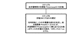
まず、設定部31は、電力供給(電力会社)側から提示される中長期的な電力需要要求に関する時系列データと、電力供給(電力会社)側から提示される充電直前の突発的な電力需要要求とを、入手部10から受け付ける。続いて、設定部31は、中長期的な電力需要要求に関する時系列データと突発的な電力需要要求とを基に、各時刻における総充電需要の目標値Ptotal_target(t)を定義(設定)する(ステップA)。
ここで、中長期的な電力需要要求に関する時系列データには、時間に依存して変化する電力価格等も含まれる。
総充電需要の目標値Ptotal_target(t)には、中長期的な電力需要要求に帰属する分として“事前スケジューリング”が含まれ、また、突発的な電力需要要求に帰属する分として“リアルタイム応答”が含まれる。
なお、総充電需要の目標値 Ptotal_target(t)の定義の行い方は、特に限定はしないが、その一例については後述する。
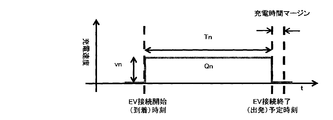
次に、各EVが駐車場に到着して充電器(配電網)へ接続されると、優先順位付与部20は、所定時刻毎に、入手部10から各EVの接続終了(出発)予定時刻を受け付ける。続いて、優先順位付与部20は、接続終了(出発)予定時刻と所望の充電時間マージンとから充電可能時間Tnを算出する。また、優先順位付与部20は、所定時刻毎に入手部10からEV毎に必要とされる充電量(必要充電量)Qnと各EVの固有の充電速度(固有充電速度)pnと、を受け付ける。
優先順位付与部20は、各時刻毎に、各EVの充電可能時間Tn、必要充電量Qnおよび固有充電速度)pnに基づいて、EVの充電優先順位を決定する。
ここで、nは各EVのID番号を示す。
なお、充電優先度を決定するために指標の定義に関しては、特に限定はしない。図3Bでは、その一例として、優先順位付与部20は、必要充電量Qnを固定充電速度pnで割ることで算出される充電必要時間Ynを、さらに充電可能時間Tnで割った値を充電優先度指標(POC)として用いる。図3Bでは、優先順位付与部20が、充電優先度指標(POC)に基づいて、EVの充電優先順位を決定し、その決定結果に応じて、EVのレコードをソートしている様子が示してある。
続いて、充電制御部32は、各EVの充電速度Pn(t)(つまり、単位時間当たりの充電量)を優先順位が上位であるものから順に加算したときの総和である総充電需要Ptotal(t)が、充電需要目標値 Ptotal_target(t)に最も近くなるまで、優先順位に従って、充電対象EV(充電対象自動車)を選択する。
充電制御部32は、充電対象EVについては充電をON、つまり、Pn(t)=pnと設定し、それ以外のEVについては充電をOFF、つまり、Pn(t)=0と設定する(ステップB)。
以上により、各EVにおいて、各時刻における充電速度Pn(t)(=pnまたは0)のスケジューリングならびにリアルタイム電力需要応答が行える。
電力系統網(電力供給)側から見える各時刻における総充電需要は、そのPn(t)の各時刻における全EV分の総和Ptotal(t)である。
なお、リアルタイムな応答後、そのままの充電需要目標値Ptotal_target(t)で充電を行ってしまうと、当初の総充電量ΣQnに変化が発生することが予想される。すなわち、出発時に所望蓄電量に達しないEVが発生してしまう恐れがある。
したがって、その総充電量ΣQnの変更を補償するため、設定部31は、リアルタイム応答直後に、総充電需要目標値Ptotal_target(t)の再定義をリアルタイムに行うことが望ましい。
以上の手法を用いることで、調整手段として、EV充電需要を操作するシステムを構築することが可能となり、再生可能電源の出力変動をも吸収することが可能となる。
なお、図3Bには、POCが1以上の値となっているEVも示してある。POCが1以上の値となっているEVは、EVが充電器(配電網)に接続された時点で既に、充電可能時間が充電必要時間よりも短かった場合に対応する。充電速度と出発予定時刻が固定である以上、充電制御側としては、充電優先順位を上げて、時間の許す限り充電を行うしかないということになる。この場合には、当然ながら、出発時の所望蓄電量を達成させることは不可能である。
なお、本形態では、EVの充電のみを制御するG2Vシステムにフォーカスして説明を行うが、充電速度にマイナス符号を許容するなどの拡張により、EVからの放電も含めた一般のV2Gシステムへの適用も可能である。
以下に、上述した充電制御方法の具体例について、シミュレーション結果を交えて説明する。
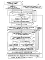
図4は、図1に示した充電制御システムにおける充電制御方法の具体例を説明するための図である。
まず、接続終了時刻入手部13は、各EVの充電器(配電網)接続時刻や充電量等に関する過去実績データ(平日・休日共に)を入手する(ステップ1)。
次に、接続終了時刻入手部13は、過去実績データを基に、各時刻における充電需要の予測(平日・休日共に、翌日~数日後まで)を行うとともに、EVの到着(充電器接続)および出発(充電器切り離し)の時刻の平均値(予測値)を算出する(ステップ2)。
また、これらと併行して、電力需要要求入手部11は、充電需要制御の目標とすべき要求電力需要の時間変化データ(電力価格などを含む)を電力供給側から入手する。このデータは、電力供給側から要求される電力需要であって、時間によって変化するものである。
そして、要求需要比率関数算出部31aは、このデータから、時間変化する要求需要比率関数F’(t)を算出する(ステップ3)。ただし、ここでは未だ、各EVの充電可能時間内での規格化は行っておらず、全EVに共通の関数となっている。この要求需要比率関数F’(t)の算出方法としては、特に限定はしない。ここでは、要求需要比率関数F’(t)を、規格化前の要求需要比率関数F’(t)=(最大電力価格―電力価格)÷(最大電力価格-最小電力価格)として算出している。
図5は、要求需要比率関数算出部31aにおける処理を説明するための図である。図5Aは電力需要要求入手部11が入手したデータを示す図である。図5Bは要求需要比率関数算出部31aにて算出された要求需要比率関数F’(t)を示す図である。
要求需要比率関数算出部31aは、図5Aに示すように時間の経過に伴い変化する電力価格に応じて、図5Bに示すように時間の経過に伴い変化する要求需要比率関数F’(t)を算出する。
なお、この要求需要比率関数F’(t)は、総充電需要の目標値Ptotal_target(t)の定義方法の一例を示す際に必要となるため説明しているが、その他の総充電需要の目標値の定義方法を用いる場合には、特にこの比率関数を算出する必要はない。
上記準備の下、接続検知部12が、EVが充電器(配電網)に接続されたことを感知すると(ステップ4)、充電量入手部14は、そのEV毎に、現蓄電量Znおよび必要充電量Qnを入手し、固定充電速度入手部15は、そのEV毎に、EV固有の固定充電速度pnを入手する(ステップ5)。
そして、充電可能時間算出部21は、接続終了時刻入手部13が算出した出発予定(予測)時刻と現在時刻とに基づいて、マージンも考慮した充電器(配電網)接続の継続保証時間である充電可能時間Tnを算出する(ステップ6)。なお、ここで示すシミュレーションでは、通勤(朝と夕方にEV運転)に使用されるEV50台を想定する。
図6は、EV50台分の充電器接続パターンの一例を示す図である。
本形態においては、EV毎に図6に示すようなランダムな充電器(配電網)の接続パターン(休日-平日-平日の3日分)を生成し、EVが運転されていない時間帯は全て充電器に接続されている、つまり充電制御対象になっているものと仮定し、それに対して、本形態を適用している。
続いて、指標算出部22は、所定時刻毎に、充電優先度の指標となる数値POCの算出を行い、所定時刻毎に、それらの値をまとめたテーブル(図3B参照)を作成する(ステップ7)。
続いて、優先順位決定部23は、そのテーブルを、充電優先度指標POCを用いてソーティングし、各時刻におけるEVの充電優先順位を決定する(ステップ8)。
ここで、充電優先度指標POCに関しては、前述したとおり特に限定しないが、図4では一つの例として、「必要充電量Qn÷固定充電速度pn÷充電可能時間Tn」をその指標とした例を示している。
その後、目標値設定部31eは、ターゲットとすべき総充電需要の目標値Ptotal_target(t)を設定する。
ここで、この総充電需要の目標値の設定手法も特に限定をしないが、その一例を、図4のフローチャートと図7Aおよび7Bの総充電需要の目標値の定義方法の概略説明に示した。
規格化部31cは、まず、EV毎に、充電可能時間帯内における平均値が“1”となるようにF’(t)を規格化して、要求需要比率関数Fn(t)を算出する(ステップ9)。
また、仮想的に充電速度が連続的に変更できると想定した場合において、フラット化充電速度算出部31bは、EV毎に、必要充電量Qnを充電可能時間Tnで割ることにより、出発時に所望充電量を満足し得る最遅の充電速度、つまり、フラット化充電速度vnを算出する(ステップ10)。
また、電力供給側から突発的な電力需要要求がある場合には(ステップ11)、補正係数算出部31dは、その要求度合いに応じて、仮想的充電速度のリアルタイム補正係数C(t)を、初期値として設定した“1”から任意の値に変更する(ステップ12)。
一方、電力供給側から突発的な電力需要要求がない場合には(ステップ11)、補正係数算出部31dは、仮想的充電速度のリアルタイム補正係数C(t)を、初期値として設定した“1”のままにする(ステップ13)。
続いて、目標値設定部31eは、仮想的フラット化充電速度vnに対して、規格化された要求需要比率関数Fn(t)とリアルタイム補正係数C(t)とを掛け合わせ、各EV毎に、各時刻における仮想的充電速度Vn(t)を算出する(ステップ14)。
続いて、目標値設定部31eは、この仮想的充電速度Vn(t)の全EVに亘る総和を総充電需要の目標値Ptotal_target(t)と定義(設定)する(ステップ15)。
以上の様な手続きにより、総充電需要の目標値Ptotal_target(t)の定義を行った後、充電制御部32は、各EVの充電速度Pn(t)(単位時間当たりの充電量)を優先順位が上位であるものから順に加算したときの総和である総充電需要Ptotal(t)が、充電需要目標値 Ptotal_target(t)に最も近くなるまで、優先順位に従って、充電対象EV(充電対象自動車)を選択する。充電制御部32は、充電対象EVについては充電をON、つまり、Pn(t)=pnと設定し、それ以外のEVについては充電をOFF、つまり、Pn(t)=0と設定する。以上により、充電制御部32は、各EVの各時刻における充電速度Pn(t)(pnまたは0)を決定する(ステップ16)。
続いて、充電制御部32は、充電速度Pn(t)を、各EV充電器へ伝達し、最終的に充電機器の制御、つまり電力需要制御がなされることとなる(ステップ17)。
図8は、EV50台を想定した場合における総充電需要の形状変化をシミュレーションした結果を示す図である。ただし、ここでは、リアルタイム応答の要請が無かったと仮定し、全時間帯でC(t)=1とした。
図8Aは、参考のため、本実施形態による充電スケジューリングを行わない場合、つまり、時間変化する電力価格データに基づいて充電コストが最小となるように各EVオーナが独自に充電スケジューリングを行った場合の結果を示した図である。
図8Aに示した場合には、スタートとなる電力価格曲線の形状にも依存するが、充電需要が特定の時間に集中をしてしまう。このため、再生可能電源の出力変動等を吸収するどころか、急峻で大きな需要変動を新たに誘発する可能性がある。
一方、図8Bは、本実施形態の充電スケジューリングの結果が示した図である。図8Bにおいて、電力需要を表すグラフをほぼ縁取るかのように描かれている実線は、総充電需要の目標値Ptotal_target(t)を表している。
図8Bに示した例では、時間帯毎に、図5Bに示した要求需要比率関数F’(t)の形状をほぼ正確に再現した充電スケジューリングが実現されている。このため、再生可能電源の出力変動等に対する調整手段となり得る多数EV連係充電システムの電力需要制御機能が十分働くことになる。
また、本実施形態では、優先順位付与部20は、時間の経過とともにEVの優先順位を再設定する。このため、各EVの充電機会の偏りを少なくすることが可能になる。
なお、本形態による充電制御により、各EVオーナが負担する充電コストが上昇してしまうように見えるが、実際には、電力系統安定化寄与に対する対価が、電力供給側から多数EV連係充電システムの運営者を介してフィードバックされるようなビジネスモデル上で使用されることを想定しているため、各EVオーナの負担する充電コストはむしろ削減される形となる。
さらに、リアルタイムにC(t)の値を初期値の“1”から任意の値へ変化させることにより、突発的な電力需要の増減要求に対する“リアルタイム応答”も可能である。
ただし、リアルタイムな電力需要応答後、そのままの充電需要の目標値Ptotal_target(t)に基づいて充電が行われてしまうと、当初の総充電量ΣQnに変化が発生することが予想される。すなわち、出発時に所望蓄電量に達しないEVが発生してしまう恐れがある。したがって、その総充電量ΣQnの変更を補償するため、リアルタイム応答直後に、総充電需要の目標値Ptotal_target(t)の再定義(再設定)をリアルタイムに行うことが望ましい。それにより、EV発車時刻における所望蓄電量の必達を実現させることが可能である。
なお、EVオーナの都合で突発的に充電器接続時間が短縮された場合は、当然ながら、出発時所望充電の必達はできない。しかしながら、予定より早く出発することを可能な限り早く充電制御側へ申告したならば、充電可能時間の更新により、優先順位が上がるため、出発時所望充電の必達の可能性を高める事ができる。
最後に、EVの充電優先順位を決定する際の方法についても補足をしておく。
上記の実施形態で示した方法に加えて、以下のような順位決定方法も考えられる。これらは、単独で用いても良いし、組み合わせて用いても良い。同じEVに対して、優先度POCとしてさらに別の尺度で優先度判定を行いたい場合には、組み合わせる方法は有効である。
(A)充電器そのものや、EVと充電器をつなぐケーブルやコネクタといった充電手段・設備への負荷量を指標(POC)として、充電優先順位を決定する方法。充電需要が集中することにより、上記のような充電手段・設備の定格容量を超えてしまう恐れがあり、充電需要を時間的もしくは空間的に分散する必要がある場合等に有効である。
(B)EV内蓄電池への負荷量や、その蓄電池の残り寿命、蓄電率(SOC)といった蓄電池状態を指標(POC)として、充電優先順位を決定する方法。EV内蓄電池の保護や長寿命化を重視する場合、蓄電量や蓄電率(SOC)によっては、早く一定の充電を行い、特定の蓄電量や蓄電率(SOC)を避けることが有効な場合がある。その様な場合等において、有効な順位決定方法である。
(C)発電所から充電器へ到達するまでの電力配電網・設備(電力配線)への局所的な負荷量を指標(POC)として、充電優先順位を決定する方法。こちらも(A)と同様に、充電需要が集中することにより、共有・共用する電力設備の定格容量を超えてしまう恐れがあり、充電需要を時間的もしくは空間的に分散する必要がある場合等に有効である。
(D)EVオーナと充電制御業者との間で結ばれるサービス品質保証契約内容または契約料金を指標(POC)として、充電優先順位を決定する方法。これは、通信分野における帯域確保などと同様のサービス品質に関する契約をベースに、特定のEVユーザの充電を優先させるものである。
(E)EVの蓄電量、EVの蓄電率、EVの蓄電量の許容範囲、EVの蓄電率の許容範囲、EVに必要となる所望充電量、EVに必要となる所望充電率、EVの許容充電速度、EVでの所望充電に必要な時間、EVの充電可能時間のいずれか、もしくは、それらのうちの複数のものに基づく指標(POC)が用いられてもよい。例えば、(所望充電量、所望充電率、または所望充電に必要な時間)/(充電可能時間)の式にて算出される値に基づく指標(POC)が用いられてもよい。
次に、本実施形態の効果を説明する。
任意時刻における、限られたEVやそれらの駐車場への充電集中の回避(EV内蓄電池や充電インフラに対する負荷の分散・最小化)が可能となる。その理由としては、充電優先順位が時々刻々と変化するような充電優先度指標を採用した場合、自動的に充電負荷が分散されることが挙げられる。
また、調整手段に対するリアルタイムな要求(需要変化要求)にも対応することができる。その理由としては、充電優先度指標として「(充電必要時間Yn)÷(充電可能時間Tn)」を採用した場合、充電時間シフトの自由度が少ないEVから充電され、一方でその自由度が大きいEVの充電は先送りされることにより、総EV充電需要全体でみた場合の充電時間のシフト自由度が自動的に最大化していることが挙げられる。また、リアルタイムに各EVの充電速度を決定する際に、中長期的な“事前スケジューリング”部分と切り離し、別途、補正係数を導入することで、充電器制御までの冗長な計算処理工程を排除し、即応性を向上させている点も挙げられる。
また、低負荷の計算処理によるスケジュール最適化が可能。その理由としては、高度な数学的手法や最適化アルゴリズムを用いずに、簡易な指標のみを用いたEVの充電優先順位付けにより、所望の充電スケジューリングが完了することが挙げられる。
また、EV台数に対するスケーラビリティの確保(EV数1台~増大過渡期対応)が可能となる。その理由としては、本実施形態は、基本的にEV台数による制限を受けない充電制御アルゴリズムとなっている点が挙げられる。
また、EV外部から充電速度を連続的に調整できない場合にも、総EV充電需要が制御可能となる。その理由としては、充電速度の連続調整の代わりに、各EV充電のON/OFF調整のみを行うことにより、総EV充電需要を変化させていることが挙げられる。
また、本実施形態で説明した総充電需要目標値の定義(設定)方法を採用することで、以下の効果も見込める。
出発時所望(満)充電の必達を実現可能である。その理由としては、充電速度が連続的に変化させられると仮定した場合に所望充電必達が保証される仮想的フラット化充電速度vnに対して、充電可能時間帯内の平均値が“1”となる様に規格化された要求需要比率関数Fn(t)を掛け合わせており、またそれと同時に、突発的な需要変化要求に対してリアルタイムに応答した場合にも、その直後に、総充電需要の目標値を再定義することにより、いかなる電力需要要求があっても、EVが充電器に接続された当初のスケジューリングにおける総充電量ΣQnに変化が発生しないことが挙げられる。ただし、EVが充電器(配電網)に接続された時点で既に、充電可能時間が充電必要時間よりも短かい場合は除く。この場合には、充電速度と出発予定時刻が固定である以上、当然ながら、出発時の所望蓄電量を達成させることは不可能である。
これにより、再生可能電源の出力変動等に対する電力調整力となり得る多数EV連係充電(G2V)システムの実用化を、さらに促進することが可能となる。
なお、本発明においては、電力アグリゲータ3a~3c内の処理は専用のハードウェアにより実現されるもの以外に、その機能を実現するためのプログラムを電力アグリゲータ3a~3cにて読取可能な記録媒体に記録し、この記録媒体に記録されたプログラムを電力アグリゲータ3a~3cに読み込ませ、実行するものであっても良い。電力アグリゲータ3a~3cにて読取可能な記録媒体とは、ICカードやメモリカード、あるいは、フロッピーディスク(登録商標)、光磁気ディスク、DVD、CD等の移設可能な記録媒体の他、電力アグリゲータ3a~3cに内蔵されたHDD等を指す。この記録媒体に記録されたプログラムは、例えば、制御ブロックにて読み込まれ、制御ブロックの制御によって、上述したものと同様の処理が行われる。
以上、実施形態を参照して本願発明を説明したが、本願発明は上記実施形態に限定されるものではない。本願発明の構成や詳細には、本願発明のスコープ内で当業者が理解し得る様々な変更をすることができる。
この出願は、2011年3月4日に出願された日本出願特願2011-047838を基礎とする優先権を主張し、その開示の全てをここに取り込む。
1 電力配電線網及び情報通信線網
2 変電所
2a 電力制御サーバ
3a~3c 電力アグリゲータ
4a,4b,4c,4d HEMS
5a~5l 電気自動車EV
6 大容量エネルギーストレージ
7 小コミュニティ
8 駐車場
9 急速充電スタンド
10 入手部
11 電力需要要求入手部
12 接続検知部
13 接続終了時刻入手部
14 充電量入手部
15 固定充電速度入手部
20 優先順位付与部
21 充電可能時間算出部
22 指標算出部
23 優先順位決定部
30 制御部
31 設定部
31a 要求需要比率関数算出部
31b フラット化充電速度算出部
31c 規格化部
31d 補正係数算出部
32 充電制御部
2 変電所
2a 電力制御サーバ
3a~3c 電力アグリゲータ
4a,4b,4c,4d HEMS
5a~5l 電気自動車EV
6 大容量エネルギーストレージ
7 小コミュニティ
8 駐車場
9 急速充電スタンド
10 入手部
11 電力需要要求入手部
12 接続検知部
13 接続終了時刻入手部
14 充電量入手部
15 固定充電速度入手部
20 優先順位付与部
21 充電可能時間算出部
22 指標算出部
23 優先順位決定部
30 制御部
31 設定部
31a 要求需要比率関数算出部
31b フラット化充電速度算出部
31c 規格化部
31d 補正係数算出部
32 充電制御部
Claims (10)
- 電力を利用して走行する複数の自動車への充電を制御する充電制御システムであって、
所定の指標に基づいて、前記複数の自動車に対して充電に関する優先順位を付与する付与手段と、
電力供給側から要求される電力需要を受け付ける受付手段と、
前記充電のオンオフについてのオンオフ設定がオン設定にされる充電対象自動車を、前記複数の自動車から前記優先順位が高い順に選択し、前記充電対象自動車のオンオフ設定をオン設定にする制御手段と、を含み、
前記制御手段は、前記充電対象自動車の数を前記電力需要の時間変化に応じて変更する、充電制御システム。 - 前記付与手段は、前記所定の指標として、前記自動車の蓄電量、前記自動車の蓄電率、前記自動車の蓄電量の許容範囲、前記自動車の蓄電率の許容範囲、前記自動車に必要となる所望充電量、前記自動車に必要となる所望充電率、前記自動車の許容充電速度、前記自動車での前記所望充電に必要な時間、前記自動車の充電可能時間のいずれか、もしくは、それらのうちの複数のものに基づく指標を用いる、請求項1に記載の充電制御システム。
- 前記付与手段は、前記所定の指標として、(前記所望充電量、前記所望充電率、または前記所望充電に必要な時間)/(前記充電可能時間)の式にて算出される値に基づく指標を用いる、請求項2に記載の充電制御システム。
- 前記制御手段は、前記自動車に接続された充電手段を制御して、当該自動車に対する充電のオンオフを制御し、
前記付与手段は、前記所定の指標として、前記充電手段の負荷量、または、前記充電手段に電力を供給する電力配線の負荷量を用いる、請求項1に記載の充電制御システム。 - 前記付与手段は、前記所定の指標として、前記自動車に搭載され前記充電のオンオフが制御される蓄電池の状態を用いる、請求項1に記載の充電制御システム。
- 前記付与手段は、前記所定の指標として、前記自動車のオーナと充電制御業者との間で締結された契約の内容を用いる、請求項1に記載の充電制御システム。
- 前記電力供給側から要求される電力需要は、突発的な電力需要を含むものである、請求項1から6のいずれか1項に記載の充電制御システム。
- 前記制御手段は、前記電力供給側から要求される電力需要の時間変化を表す関数を基に前記複数の自動車の単位時間当たりの充電量を算出し、当該充電量の総和を用いて、充電需要の目標値を設定し、前記充電対象自動車の数を前記目標値の時間変化に応じて変更する、請求項1から6のいずれか1項に記載の充電制御システム。
- 電力を利用して走行する複数の自動車への充電を制御する充電制御システムでの充電制御方法であって、
所定の指標に基づいて、前記複数の自動車に対して充電に関する優先順位を付与し、
電力供給側から要求される電力需要を受け付け、
前記充電のオンオフについてのオンオフ設定がオン設定にされる充電対象自動車を、前記複数の自動車から前記優先順位が高い順に選択し、前記充電対象自動車のオンオフ設定をオン設定にする制御を行い、
前記制御では、前記充電対象自動車の数を前記電力需要の時間変化に応じて変更する、充電制御方法。 - 電力を利用して走行する複数の自動車への充電を制御するためのコンピュータに、
所定の指標に基づいて、前記複数の自動車に対して充電に関する優先順位を付与する付与手順と、
電力供給側から要求される電力需要を受け付ける受付手順と、
前記充電のオンオフについてのオンオフ設定がオン設定にされる充電対象自動車を、前記複数の自動車から前記優先順位が高い順に選択し、前記充電対象自動車のオンオフ設定をオン設定に制御手順と、を実行させ、
前記制御手順では、前記充電対象自動車の数を前記電力需要の時間変化に応じて変更する、プログラムを記録したコンピュータ読み取り可能な記録媒体。
Priority Applications (3)
| Application Number | Priority Date | Filing Date | Title |
|---|---|---|---|
| JP2013503432A JP6052621B2 (ja) | 2011-03-04 | 2012-02-13 | 充電制御システム、充電制御方法及びプログラム |
| US14/002,678 US9248752B2 (en) | 2011-03-04 | 2012-02-13 | Charging control system, charging control method, and recording medium |
| EP12754793.3A EP2683053A4 (en) | 2011-03-04 | 2012-02-13 | CHARGING CONTROL SYSTEM, CHARGING CONTROL METHOD AND RECORDING MEDIUM |
Applications Claiming Priority (2)
| Application Number | Priority Date | Filing Date | Title |
|---|---|---|---|
| JP2011047838 | 2011-03-04 | ||
| JP2011-047838 | 2011-03-04 |
Publications (1)
| Publication Number | Publication Date |
|---|---|
| WO2012120976A1 true WO2012120976A1 (ja) | 2012-09-13 |
Family
ID=46797945
Family Applications (1)
| Application Number | Title | Priority Date | Filing Date |
|---|---|---|---|
| PCT/JP2012/053263 Ceased WO2012120976A1 (ja) | 2011-03-04 | 2012-02-13 | 充電制御システム、充電制御方法及び記録媒体 |
Country Status (4)
| Country | Link |
|---|---|
| US (1) | US9248752B2 (ja) |
| EP (1) | EP2683053A4 (ja) |
| JP (1) | JP6052621B2 (ja) |
| WO (1) | WO2012120976A1 (ja) |
Cited By (16)
| Publication number | Priority date | Publication date | Assignee | Title |
|---|---|---|---|---|
| JP2013055731A (ja) * | 2011-09-01 | 2013-03-21 | Nissan Motor Co Ltd | 充電システム及び充電方法 |
| JP2015171188A (ja) * | 2014-03-05 | 2015-09-28 | 清水建設株式会社 | 充放電管理装置、充放電管理方法及びプログラム |
| EP2774801A3 (en) * | 2013-03-04 | 2015-10-07 | LG CNS Co., Ltd. | Method and system of dynamically charging electric vehicle |
| JP2017163652A (ja) * | 2016-03-08 | 2017-09-14 | 本田技研工業株式会社 | 電源システム |
| KR20180012605A (ko) * | 2016-07-27 | 2018-02-06 | 주식회사 케이티 | 전기차 충전소의 충전기를 제어하는 충전기 제어 장치 및 방법 |
| JP2020018103A (ja) * | 2018-07-25 | 2020-01-30 | 東芝デジタルソリューションズ株式会社 | 充電管理システム、方法及びプログラム |
| JP2020018104A (ja) * | 2018-07-25 | 2020-01-30 | 東芝デジタルソリューションズ株式会社 | 充電制御装置、充電管理システム、方法及びプログラム |
| WO2020194010A1 (ja) * | 2019-03-22 | 2020-10-01 | 日産自動車株式会社 | 受電要素の受電制御方法、及び受電制御装置 |
| CN113401007A (zh) * | 2020-03-16 | 2021-09-17 | 丰田自动车株式会社 | 电力管理装置以及电力管理方法 |
| JP2022122537A (ja) * | 2021-02-10 | 2022-08-23 | 日産自動車株式会社 | 受電要素の受電制御方法及び受電要素の受電制御装置 |
| JP2023027620A (ja) * | 2021-08-17 | 2023-03-02 | トヨタ自動車株式会社 | 制御装置、プログラム、及び、電力管理システム |
| JP2023029011A (ja) * | 2021-08-20 | 2023-03-03 | トヨタ自動車株式会社 | 非接触電力伝送システム、車両、サーバおよび送電装置 |
| JP2023041327A (ja) * | 2021-09-13 | 2023-03-24 | 日産自動車株式会社 | 充電装置、および、当該充電装置を備えた電力システム、ならびに、充電方法 |
| CN116667492A (zh) * | 2023-06-06 | 2023-08-29 | 深圳三晖能源科技有限公司 | 基于物联网的充电控制方法及装置、电子设备、存储介质 |
| US11843271B2 (en) | 2019-03-22 | 2023-12-12 | Nissan Motor Co., Ltd. | Power reception control method for power storage element and power reception control device |
| JP7761111B1 (ja) * | 2024-10-09 | 2025-10-28 | 富士電機株式会社 | 制御システム |
Families Citing this family (35)
| Publication number | Priority date | Publication date | Assignee | Title |
|---|---|---|---|---|
| JP6399928B2 (ja) * | 2011-08-16 | 2018-10-03 | チャージ ピーク リミテッド | 電気自動車ネットワークにおける負荷の推定および管理 |
| JP5919525B2 (ja) * | 2011-11-22 | 2016-05-18 | パナソニックIpマネジメント株式会社 | 車両管理システム |
| WO2013144577A2 (en) * | 2012-03-30 | 2013-10-03 | Sony Corporation | Energy storage |
| US9511675B2 (en) * | 2013-09-13 | 2016-12-06 | Nissan North America, Inc. | Methods of decreasing peak energy consumption |
| DE102014109939A1 (de) * | 2014-07-15 | 2016-01-21 | EnBW Energie Baden-Württemberg AG | Lokales Ladenetz mit wenigstens einem Ladesystem zum Laden von Elektrofahrzeugen, Ladesystem mit wenigstens einer Ladestation und Verfahren zum Betreiben eines Ladenetzes mit wenigstens einem Ladesystem zum Laden von Elektrofahrzeugen |
| JP6544720B2 (ja) * | 2015-06-17 | 2019-07-17 | パナソニックIpマネジメント株式会社 | 管理装置、管理方法、及び管理用プログラム |
| JP6597218B2 (ja) | 2015-11-17 | 2019-10-30 | オムロン株式会社 | バッテリ予約装置およびバッテリ予約方法 |
| JP6724343B2 (ja) | 2015-11-17 | 2020-07-15 | オムロン株式会社 | 予約管理装置、予約管理システムおよび予約管理方法 |
| JP6582909B2 (ja) | 2015-11-17 | 2019-10-02 | オムロン株式会社 | バッテリ予約装置およびバッテリ予約方法 |
| JP6766343B2 (ja) * | 2015-11-17 | 2020-10-14 | オムロン株式会社 | バッテリ予約装置 |
| SE541327C2 (sv) * | 2016-03-01 | 2019-07-02 | Hybricon Bus Systems Ab | System och förfarande för kommunikation, prioritering, dirigering och laddning av elfordon vid laddstationer med eller utan lagringskapacitet |
| CN105654622B (zh) * | 2016-03-04 | 2019-10-15 | 深圳市速满跑科技有限公司 | 充电桩管理方法及系统 |
| US10468897B2 (en) * | 2016-10-14 | 2019-11-05 | International Business Machines Corporation | Wireless electric power sharing between vehicles |
| CN106494246B (zh) * | 2016-10-19 | 2019-01-25 | 广州乐盈信息科技股份有限公司 | 充电桩充电控制系统及方法 |
| US12261432B2 (en) | 2016-12-20 | 2025-03-25 | Ecojiva Llc | Electrical load management system |
| US20180175666A1 (en) * | 2016-12-20 | 2018-06-21 | Ecojiva, LLC | Electrical load management system |
| JP6624084B2 (ja) * | 2017-01-12 | 2019-12-25 | トヨタ自動車株式会社 | 電動車両 |
| DE102017209716A1 (de) * | 2017-06-08 | 2018-12-13 | Audi Ag | Verfahren zum Steuern eines Ladevorganges einer Energiespeichereinrichtung eines Kraftfahrzeugs, Steuereinrichtung, Lademanagementeinrichtung, Servervorrichtung, und Kraftfahrzeug |
| DE102017006678A1 (de) * | 2017-07-14 | 2019-01-17 | Drägerwerk AG & Co. KGaA | Kaskadierbarer Mehrfachlader und Verfahren zu dessen Betrieb |
| JP6959063B2 (ja) * | 2017-08-04 | 2021-11-02 | アズビル株式会社 | 充電制御システム |
| JP6879861B2 (ja) * | 2017-08-08 | 2021-06-02 | アズビル株式会社 | 電動アクチュエータ |
| DE102018109078A1 (de) * | 2018-04-17 | 2019-10-17 | Wobben Properties Gmbh | Ladestation zum Laden von Elektrofahrzeugen |
| DE102018109077A1 (de) | 2018-04-17 | 2019-10-17 | Wobben Properties Gmbh | Ladestation zum Laden von Elektrofahrzeugen |
| US10647218B1 (en) * | 2019-04-12 | 2020-05-12 | Bordin New Energy Vehicle Corporation, Inc. | System for thermally conditioning a battery pack of an electric vehicle |
| GB201907140D0 (en) * | 2019-05-21 | 2019-07-03 | Rolls Royce Plc | Forecast of electric vehicles state of charge and energy storage capacity |
| CN110601293A (zh) * | 2019-09-18 | 2019-12-20 | 深圳来电科技有限公司 | 移动电源租赁设备控制移动电源充电的方法及设备 |
| CN110525264B (zh) * | 2019-09-22 | 2023-02-28 | 国网山东省电力公司莱芜供电公司 | 一种提升并联充电桩运行可靠性的控制系统及控制方法 |
| CN112208377B (zh) * | 2020-09-30 | 2022-03-15 | 重庆长安新能源汽车科技有限公司 | 一种家用交流充电桩、系统及充电方法 |
| DE102021103044A1 (de) | 2021-02-10 | 2022-08-11 | Audi Aktiengesellschaft | Verfahren zum Austauschen elektrischer Energie |
| CN113500940B (zh) * | 2021-07-08 | 2022-06-28 | 东北电力大学 | 一种基于粒子群算法的电动汽车有序充放电动态优化策略 |
| FI131650B1 (en) * | 2022-06-17 | 2025-08-22 | Liikennevirta Oy / Virta Ltd | A method and an apparatus for managing charging transactions and loads at charging stations |
| US12415436B2 (en) * | 2022-07-28 | 2025-09-16 | Rivian Ip Holdings, Llc | Non-wire alternatives grid deferrals |
| JP7673711B2 (ja) * | 2022-08-10 | 2025-05-09 | トヨタ自動車株式会社 | エネルギーマネジメント方法、プログラム、コンピュータ装置 |
| CN119953225B (zh) * | 2023-11-09 | 2025-10-31 | 重庆长安汽车股份有限公司 | 一种能源共享调度方法、充电方法、交通工具及服务端 |
| JP2025186831A (ja) * | 2024-06-12 | 2025-12-24 | 株式会社日立製作所 | 充電システムおよび充電方法 |
Citations (6)
| Publication number | Priority date | Publication date | Assignee | Title |
|---|---|---|---|---|
| JP2000209707A (ja) | 1999-01-07 | 2000-07-28 | Mitsubishi Electric Corp | 電気自動車の充電計画装置 |
| JP2001069678A (ja) * | 1999-08-31 | 2001-03-16 | Seikichi Kobayashi | 車両等の充電制御装置 |
| JP2008067418A (ja) * | 2006-09-04 | 2008-03-21 | Nippon Telegr & Teleph Corp <Ntt> | 充電制御方法、蓄電装置および充電制御システム |
| JP2009136109A (ja) * | 2007-11-30 | 2009-06-18 | Toyota Motor Corp | 充電制御装置および充電制御方法 |
| JP2010110173A (ja) * | 2008-10-31 | 2010-05-13 | Honda Motor Co Ltd | 電力供給制御装置 |
| JP2010187453A (ja) * | 2009-02-11 | 2010-08-26 | Chubu Electric Power Co Inc | 集合住宅用の車両充電システム及び充電制御装置 |
Family Cites Families (3)
| Publication number | Priority date | Publication date | Assignee | Title |
|---|---|---|---|---|
| US8054048B2 (en) * | 2007-10-04 | 2011-11-08 | GM Global Technology Operations LLC | Power grid load management for plug-in vehicles |
| AT506911B1 (de) | 2008-06-05 | 2012-06-15 | Andexlinger Erich | Verfahren und system zum regeln der intensität des ladens einer batterie |
| US8085034B2 (en) * | 2008-10-31 | 2011-12-27 | Yaniv Sirton | Managing charging of electric vehicles |
-
2012
- 2012-02-13 US US14/002,678 patent/US9248752B2/en active Active
- 2012-02-13 WO PCT/JP2012/053263 patent/WO2012120976A1/ja not_active Ceased
- 2012-02-13 EP EP12754793.3A patent/EP2683053A4/en not_active Withdrawn
- 2012-02-13 JP JP2013503432A patent/JP6052621B2/ja active Active
Patent Citations (6)
| Publication number | Priority date | Publication date | Assignee | Title |
|---|---|---|---|---|
| JP2000209707A (ja) | 1999-01-07 | 2000-07-28 | Mitsubishi Electric Corp | 電気自動車の充電計画装置 |
| JP2001069678A (ja) * | 1999-08-31 | 2001-03-16 | Seikichi Kobayashi | 車両等の充電制御装置 |
| JP2008067418A (ja) * | 2006-09-04 | 2008-03-21 | Nippon Telegr & Teleph Corp <Ntt> | 充電制御方法、蓄電装置および充電制御システム |
| JP2009136109A (ja) * | 2007-11-30 | 2009-06-18 | Toyota Motor Corp | 充電制御装置および充電制御方法 |
| JP2010110173A (ja) * | 2008-10-31 | 2010-05-13 | Honda Motor Co Ltd | 電力供給制御装置 |
| JP2010187453A (ja) * | 2009-02-11 | 2010-08-26 | Chubu Electric Power Co Inc | 集合住宅用の車両充電システム及び充電制御装置 |
Non-Patent Citations (2)
| Title |
|---|
| G.K. VENAYAGAMOORTHY ET AL.: "Real-Time Modeling of Distributed Plug-in Vehicles for V2G Transactions", ENERGY CONVERSION CONGRESS AND EXPOSITION, 2009. ECCE 2009, 2009, pages 3937 - 3941 |
| See also references of EP2683053A4 |
Cited By (31)
| Publication number | Priority date | Publication date | Assignee | Title |
|---|---|---|---|---|
| JP2013055731A (ja) * | 2011-09-01 | 2013-03-21 | Nissan Motor Co Ltd | 充電システム及び充電方法 |
| EP2774801A3 (en) * | 2013-03-04 | 2015-10-07 | LG CNS Co., Ltd. | Method and system of dynamically charging electric vehicle |
| US9623762B2 (en) | 2013-03-04 | 2017-04-18 | Lg Cns Co., Ltd. | Method and system of dynamically charging electric vehicle |
| JP2015171188A (ja) * | 2014-03-05 | 2015-09-28 | 清水建設株式会社 | 充放電管理装置、充放電管理方法及びプログラム |
| JP2017163652A (ja) * | 2016-03-08 | 2017-09-14 | 本田技研工業株式会社 | 電源システム |
| KR20180012605A (ko) * | 2016-07-27 | 2018-02-06 | 주식회사 케이티 | 전기차 충전소의 충전기를 제어하는 충전기 제어 장치 및 방법 |
| KR102285989B1 (ko) | 2016-07-27 | 2021-08-04 | 주식회사 케이티 | 전기차 충전소의 충전기를 제어하는 충전기 제어 장치 및 방법 |
| JP2020018103A (ja) * | 2018-07-25 | 2020-01-30 | 東芝デジタルソリューションズ株式会社 | 充電管理システム、方法及びプログラム |
| JP2020018104A (ja) * | 2018-07-25 | 2020-01-30 | 東芝デジタルソリューションズ株式会社 | 充電制御装置、充電管理システム、方法及びプログラム |
| JP7173674B2 (ja) | 2018-07-25 | 2022-11-16 | 東芝デジタルソリューションズ株式会社 | 充電制御装置、充電管理システム、方法及びプログラム |
| JP7168293B2 (ja) | 2018-07-25 | 2022-11-09 | 東芝デジタルソリューションズ株式会社 | 充電管理システム、方法及びプログラム |
| WO2020194010A1 (ja) * | 2019-03-22 | 2020-10-01 | 日産自動車株式会社 | 受電要素の受電制御方法、及び受電制御装置 |
| JPWO2020194010A1 (ja) * | 2019-03-22 | 2020-10-01 | ||
| US11843271B2 (en) | 2019-03-22 | 2023-12-12 | Nissan Motor Co., Ltd. | Power reception control method for power storage element and power reception control device |
| US11390186B2 (en) | 2019-03-22 | 2022-07-19 | Nissan Motor Co., Ltd. | Power reception control method for power reception element and power reception control device |
| JP7213335B2 (ja) | 2019-03-22 | 2023-01-26 | 日産自動車株式会社 | 受電要素の受電制御方法、及び受電制御装置 |
| JP7251503B2 (ja) | 2020-03-16 | 2023-04-04 | トヨタ自動車株式会社 | 電力管理装置、及び電力管理方法 |
| CN113401007B (zh) * | 2020-03-16 | 2024-05-03 | 丰田自动车株式会社 | 电力管理装置以及电力管理方法 |
| JP2021150988A (ja) * | 2020-03-16 | 2021-09-27 | トヨタ自動車株式会社 | 電力管理装置、及び電力管理方法 |
| CN113401007A (zh) * | 2020-03-16 | 2021-09-17 | 丰田自动车株式会社 | 电力管理装置以及电力管理方法 |
| US11858371B2 (en) | 2020-03-16 | 2024-01-02 | Toyota Jidosha Kabushiki Kaisha | Power management apparatus and power management method |
| JP7569703B2 (ja) | 2021-02-10 | 2024-10-18 | 日産自動車株式会社 | 受電要素の受電制御方法及び受電要素の受電制御装置 |
| JP2022122537A (ja) * | 2021-02-10 | 2022-08-23 | 日産自動車株式会社 | 受電要素の受電制御方法及び受電要素の受電制御装置 |
| JP2023027620A (ja) * | 2021-08-17 | 2023-03-02 | トヨタ自動車株式会社 | 制御装置、プログラム、及び、電力管理システム |
| JP7619206B2 (ja) | 2021-08-17 | 2025-01-22 | トヨタ自動車株式会社 | 制御装置、プログラム、及び、電力管理システム |
| JP7563333B2 (ja) | 2021-08-20 | 2024-10-08 | トヨタ自動車株式会社 | 非接触電力伝送システム、車両、サーバおよび送電装置 |
| JP2023029011A (ja) * | 2021-08-20 | 2023-03-03 | トヨタ自動車株式会社 | 非接触電力伝送システム、車両、サーバおよび送電装置 |
| JP2023041327A (ja) * | 2021-09-13 | 2023-03-24 | 日産自動車株式会社 | 充電装置、および、当該充電装置を備えた電力システム、ならびに、充電方法 |
| JP7739881B2 (ja) | 2021-09-13 | 2025-09-17 | 日産自動車株式会社 | 充電装置、および、当該充電装置を備えた電力システム、ならびに、充電方法 |
| CN116667492A (zh) * | 2023-06-06 | 2023-08-29 | 深圳三晖能源科技有限公司 | 基于物联网的充电控制方法及装置、电子设备、存储介质 |
| JP7761111B1 (ja) * | 2024-10-09 | 2025-10-28 | 富士電機株式会社 | 制御システム |
Also Published As
| Publication number | Publication date |
|---|---|
| EP2683053A1 (en) | 2014-01-08 |
| US20130335032A1 (en) | 2013-12-19 |
| JPWO2012120976A1 (ja) | 2014-07-17 |
| US9248752B2 (en) | 2016-02-02 |
| JP6052621B2 (ja) | 2016-12-27 |
| EP2683053A4 (en) | 2015-05-20 |
Similar Documents
| Publication | Publication Date | Title |
|---|---|---|
| JP6052621B2 (ja) | 充電制御システム、充電制御方法及びプログラム | |
| JP5818175B2 (ja) | 充電制御システム、充電制御方法及びプログラム | |
| JP6473983B2 (ja) | 電力アグリゲータ、充電方法及びプログラム | |
| Honarmand et al. | Optimal scheduling of electric vehicles in an intelligent parking lot considering vehicle-to-grid concept and battery condition | |
| Brenna et al. | Challenges in energy systems for the smart-cities of the future | |
| Nguyen et al. | Dynamic demand control of electric vehicles to support power grid with high penetration level of renewable energy | |
| Wang et al. | Integrated energy exchange scheduling for multimicrogrid system with electric vehicles | |
| JPWO2013031036A1 (ja) | 充電制御システム、充電制御方法及びプログラム | |
| US8963493B2 (en) | Charging control system | |
| WO2013065419A1 (ja) | 充電制御装置、電池管理装置、充電制御方法および記録媒体 | |
| Anastasiadis et al. | Electric vehicle charging in stochastic smart microgrid operation with fuel cell and RES units | |
| JP2022139814A (ja) | 制御システム、及びエネルギーマネジメント方法 | |
| JP2019033629A (ja) | 電力制御方法、制御装置、充電システム及びプログラム | |
| CN114365370A (zh) | 区域能量管理装置以及区域能量管理方法 | |
| Striani et al. | Wind based charging via autonomously controlled EV chargers under grid constraints | |
| Adhikary et al. | Bidirectional operation of electric vehicle charger incorporating grids and home energy storage: V2G/G2V/V2H/V2X for sustainable development | |
| Hussain et al. | Mobility-aware vehicle-to-grid (V2G) optimization for uniform utilization in smart grid based power distribution network | |
| Logenthiran et al. | Multi-agent system for managing a power distribution system with plug-in hybrid electrical vehicles in smart grid | |
| Xiao et al. | A systematized framework to optimize grid-interactive charging process of electric vehicles integrated with buildings and distributed renewable sources | |
| Elgammal et al. | Optimal electric vehicle charging control strategy powered by grid linked hybrid PV wind battery renewable energy system | |
| US20250153594A1 (en) | Systems and methods for managing energy resources for multiple vehicles | |
| US20260054597A1 (en) | System and method for operational efficiency of ev charging stations in a building | |
| Senthil Kumar | The multi-objective optimizations of the integrated zero-energy and positive-energy systems consisting of transportation buildings and new energy vehicles | |
| Peng | Charge Park Vehicle-to-Grid Service: Modeling, Control, and Optimization | |
| Su et al. | Smart charging of fleet and personal electric vehicles through joint vehicle-to-grid optimization |
Legal Events
| Date | Code | Title | Description |
|---|---|---|---|
| 121 | Ep: the epo has been informed by wipo that ep was designated in this application |
Ref document number: 12754793 Country of ref document: EP Kind code of ref document: A1 |
|
| ENP | Entry into the national phase |
Ref document number: 2013503432 Country of ref document: JP Kind code of ref document: A |
|
| WWE | Wipo information: entry into national phase |
Ref document number: 14002678 Country of ref document: US |
|
| NENP | Non-entry into the national phase |
Ref country code: DE |