WO2012121054A1 - 流体通路を内部に備えたハウジングへのチェックバルブの取付け手段 - Google Patents
流体通路を内部に備えたハウジングへのチェックバルブの取付け手段 Download PDFInfo
- Publication number
- WO2012121054A1 WO2012121054A1 PCT/JP2012/054871 JP2012054871W WO2012121054A1 WO 2012121054 A1 WO2012121054 A1 WO 2012121054A1 JP 2012054871 W JP2012054871 W JP 2012054871W WO 2012121054 A1 WO2012121054 A1 WO 2012121054A1
- Authority
- WO
- WIPO (PCT)
- Prior art keywords
- check valve
- housing
- space
- valve
- fluid passage
- Prior art date
- Legal status (The legal status is an assumption and is not a legal conclusion. Google has not performed a legal analysis and makes no representation as to the accuracy of the status listed.)
- Ceased
Links
Images

Classifications
-
- B—PERFORMING OPERATIONS; TRANSPORTING
- B25—HAND TOOLS; PORTABLE POWER-DRIVEN TOOLS; MANIPULATORS
- B25B—TOOLS OR BENCH DEVICES NOT OTHERWISE PROVIDED FOR, FOR FASTENING, CONNECTING, DISENGAGING OR HOLDING
- B25B27/00—Hand tools, specially adapted for fitting together or separating parts or objects whether or not involving some deformation, not otherwise provided for
- B25B27/14—Hand tools, specially adapted for fitting together or separating parts or objects whether or not involving some deformation, not otherwise provided for for assembling objects other than by press fit or detaching same
- B25B27/24—Hand tools, specially adapted for fitting together or separating parts or objects whether or not involving some deformation, not otherwise provided for for assembling objects other than by press fit or detaching same mounting or demounting valves
-
- F—MECHANICAL ENGINEERING; LIGHTING; HEATING; WEAPONS; BLASTING
- F02—COMBUSTION ENGINES; HOT-GAS OR COMBUSTION-PRODUCT ENGINE PLANTS
- F02M—SUPPLYING COMBUSTION ENGINES IN GENERAL WITH COMBUSTIBLE MIXTURES OR CONSTITUENTS THEREOF
- F02M59/00—Pumps specially adapted for fuel-injection and not provided for in groups F02M39/00 -F02M57/00, e.g. rotary cylinder-block type of pumps
- F02M59/44—Details, components parts, or accessories not provided for in, or of interest apart from, the apparatus of groups F02M59/02 - F02M59/42; Pumps having transducers, e.g. to measure displacement of pump rack or piston
- F02M59/48—Assembling; Disassembling; Replacing
-
- F—MECHANICAL ENGINEERING; LIGHTING; HEATING; WEAPONS; BLASTING
- F02—COMBUSTION ENGINES; HOT-GAS OR COMBUSTION-PRODUCT ENGINE PLANTS
- F02M—SUPPLYING COMBUSTION ENGINES IN GENERAL WITH COMBUSTIBLE MIXTURES OR CONSTITUENTS THEREOF
- F02M59/00—Pumps specially adapted for fuel-injection and not provided for in groups F02M39/00 -F02M57/00, e.g. rotary cylinder-block type of pumps
- F02M59/44—Details, components parts, or accessories not provided for in, or of interest apart from, the apparatus of groups F02M59/02 - F02M59/42; Pumps having transducers, e.g. to measure displacement of pump rack or piston
- F02M59/46—Valves
-
- F—MECHANICAL ENGINEERING; LIGHTING; HEATING; WEAPONS; BLASTING
- F02—COMBUSTION ENGINES; HOT-GAS OR COMBUSTION-PRODUCT ENGINE PLANTS
- F02M—SUPPLYING COMBUSTION ENGINES IN GENERAL WITH COMBUSTIBLE MIXTURES OR CONSTITUENTS THEREOF
- F02M63/00—Other fuel-injection apparatus having pertinent characteristics not provided for in groups F02M39/00 - F02M57/00 or F02M67/00; Details, component parts, or accessories of fuel-injection apparatus, not provided for in, or of interest apart from, the apparatus of groups F02M39/00 - F02M61/00 or F02M67/00; Combination of fuel pump with other devices, e.g. lubricating oil pump
- F02M63/0012—Valves
- F02M63/0031—Valves characterized by the type of valves, e.g. special valve member details, valve seat details, valve housing details
- F02M63/0054—Check valves
-
- F—MECHANICAL ENGINEERING; LIGHTING; HEATING; WEAPONS; BLASTING
- F04—POSITIVE - DISPLACEMENT MACHINES FOR LIQUIDS; PUMPS FOR LIQUIDS OR ELASTIC FLUIDS
- F04B—POSITIVE-DISPLACEMENT MACHINES FOR LIQUIDS; PUMPS
- F04B39/00—Component parts, details, or accessories, of pumps or pumping systems specially adapted for elastic fluids, not otherwise provided for in, or of interest apart from, groups F04B25/00 - F04B37/00
- F04B39/10—Adaptations or arrangements of distribution members
- F04B39/1006—Adaptations or arrangements of distribution members the members being ball valves
-
- F—MECHANICAL ENGINEERING; LIGHTING; HEATING; WEAPONS; BLASTING
- F16—ENGINEERING ELEMENTS AND UNITS; GENERAL MEASURES FOR PRODUCING AND MAINTAINING EFFECTIVE FUNCTIONING OF MACHINES OR INSTALLATIONS; THERMAL INSULATION IN GENERAL
- F16K—VALVES; TAPS; COCKS; ACTUATING-FLOATS; DEVICES FOR VENTING OR AERATING
- F16K15/00—Check valves
- F16K15/02—Check valves with guided rigid valve members
- F16K15/04—Check valves with guided rigid valve members shaped as balls
- F16K15/044—Check valves with guided rigid valve members shaped as balls spring-loaded
-
- F—MECHANICAL ENGINEERING; LIGHTING; HEATING; WEAPONS; BLASTING
- F16—ENGINEERING ELEMENTS AND UNITS; GENERAL MEASURES FOR PRODUCING AND MAINTAINING EFFECTIVE FUNCTIONING OF MACHINES OR INSTALLATIONS; THERMAL INSULATION IN GENERAL
- F16K—VALVES; TAPS; COCKS; ACTUATING-FLOATS; DEVICES FOR VENTING OR AERATING
- F16K17/00—Safety valves; Equalising valves, e.g. pressure relief valves
- F16K17/02—Safety valves; Equalising valves, e.g. pressure relief valves opening on surplus pressure on one side; closing on insufficient pressure on one side
- F16K17/04—Safety valves; Equalising valves, e.g. pressure relief valves opening on surplus pressure on one side; closing on insufficient pressure on one side spring-loaded
- F16K17/0406—Safety valves; Equalising valves, e.g. pressure relief valves opening on surplus pressure on one side; closing on insufficient pressure on one side spring-loaded in the form of balls
-
- F—MECHANICAL ENGINEERING; LIGHTING; HEATING; WEAPONS; BLASTING
- F16—ENGINEERING ELEMENTS AND UNITS; GENERAL MEASURES FOR PRODUCING AND MAINTAINING EFFECTIVE FUNCTIONING OF MACHINES OR INSTALLATIONS; THERMAL INSULATION IN GENERAL
- F16K—VALVES; TAPS; COCKS; ACTUATING-FLOATS; DEVICES FOR VENTING OR AERATING
- F16K27/00—Construction of housing; Use of materials therefor
- F16K27/02—Construction of housing; Use of materials therefor of lift valves
- F16K27/0209—Check valves or pivoted valves
-
- Y—GENERAL TAGGING OF NEW TECHNOLOGICAL DEVELOPMENTS; GENERAL TAGGING OF CROSS-SECTIONAL TECHNOLOGIES SPANNING OVER SEVERAL SECTIONS OF THE IPC; TECHNICAL SUBJECTS COVERED BY FORMER USPC CROSS-REFERENCE ART COLLECTIONS [XRACs] AND DIGESTS
- Y10—TECHNICAL SUBJECTS COVERED BY FORMER USPC
- Y10T—TECHNICAL SUBJECTS COVERED BY FORMER US CLASSIFICATION
- Y10T137/00—Fluid handling
- Y10T137/598—With repair, tapping, assembly, or disassembly means
- Y10T137/6109—Tool for applying or removing valve or valve member
Definitions
- the present invention relates to a means for attaching a check valve to a housing having a fluid passage therein.
- Patent Document 1 shows a conventional structure of a fuel pump and a fuel check valve attached to the fuel pump
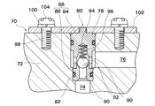
- FIG. 4 shows the conventional structure.
- the casing 72 of the fuel pump 70 has an upstream fuel passage 74 into which fuel from a fuel tank (not shown) is introduced, and a downstream fuel passage 76 that supplies fuel to the engine (not shown).
- a housing space 78 is formed which communicates the upstream fuel passage 74 and the downstream fuel passage 76 and is drilled from the outer surface of the casing 72 toward the inside.
- the fuel check valve 80 is inserted into the housing space 78 of the fuel pump 70, and its insertion tip is brought into contact with the bottom surface 82 of the housing space 78, and then the fuel check valve 80 is inserted into the casing of the fuel pump 70.
- a fuel check valve 80 is fixed to the fuel pump 70 by means of a slip-out preventing means so that the fuel pump 70 does not slip out. The escape prevention means will be described later.
- the fuel check valve 80 has a body 88 composed of a main member 84 and a seat member 86, and fuel communication passages 90 are formed in the body 88 and open at two locations.
- one opening of the fuel communication passage 90 communicates with the upstream fuel passage 74, and the other opening of the fuel communication passage 90 is the downstream fuel passage 76. Is set to contact.
- a valve seat 92 is provided at one end of the seat member 86, and the valve seat 92 is located in the middle of the fuel communication passage 90 of the fuel check valve 80.
- a ball valve 94 for opening and closing the fuel communication passage 90 and a spring 96 for urging the ball valve 94 in the direction of seating on the valve seat 92 are provided.
- the ball valve 94 is seated on the valve seat 92 by the urging force of the spring 96 when the engine is stopped, and the fuel communication passage 90 is closed.
- the passage 76 is blocked.
- the fuel pressure in the upstream fuel passage 74 becomes high, the fuel pressure resists the spring 96, and the ball valve 94 is separated from the valve seat 92 to open the fuel communication passage 90.
- the passage 74 communicates with the downstream fuel passage 76.
- the casing 72 of the fuel pump 70 is provided with a plurality of female screw portions 98 around the position of the accommodation space 78.
- a plate 102 having a hole 100 having a diameter larger than that of the screw portion is attached to the casing 72 of the fuel pump 70 at a position matching the female screw portion 98.
- the hole 100 of the plate 102 is connected to the female screw portion 98 of the casing 72.
- the plate 102 is joined to the casing 72 in accordance with the positions of Thereafter, the male screw 104 is inserted from the hole 100 of the plate 102 and the male screw 104 and the female screw portion 98 of the casing 72 are screwed together, thereby fixing the plate 102 to the casing 72 of the fuel pump 70.
- the fuel check valve 80 inserted into the storage space 78 comes into contact with the plate 102 whose rear end portion is fixed to the casing 72 and the insertion front end portion comes into contact with the bottom surface 82 of the storage space 78. Is sandwiched between the casing 72 and the plate 102. As a result, the fuel check valve 80 is prevented from coming out of the accommodation space 78 and the fuel check valve 80 is prevented from rattling in the accommodation space 78.
- Patent Document 1 a female screw portion 98 formed in a casing 72 of a fuel pump 70, a plate 102 for preventing the fuel check valve 80 from coming out and rattling, and the plate 102 as a female screw of the casing 72 are disclosed.
- the male screw 104 for screwing into the portion 98 constitutes a means for preventing the fuel check valve 80 from coming into the fuel pump 70.
- the escape prevention means prevents the fuel check valve 80 from coming out of the accommodation space 78 and prevents the fuel check valve 80 from rattling in the accommodation space 78.
- Patent Document 2 discloses a configuration different from that of Patent Document 1 as means for fixing the fuel check valve and the fuel pump.
- a female screw portion is formed on the inner wall surface of the housing space of the casing of the fuel pump, and a male screw portion is formed on the outer wall surface of the fuel check valve.
- the fuel pump and the fuel check valve are fixed by screwing the female screw portion and the male screw portion.
- the structure of the fuel check valve in Patent Document 2 is the same as the structure of the fuel check valve in Patent Document 1.
- Patent Document 1 as a means for preventing the fuel pump 70 and the fuel check valve 80 from coming off, a female for fixing the plate 102 to the casing 72 of the fuel pump 70 around the position of the accommodation space 78 is used. A plurality of screw portions 98 are provided. Since the plurality of female screw portions 98 are formed in the casing 72, the casing 72 of the fuel pump 70 has a drawback of becoming large. Since the fuel check valve 80 shown in Patent Document 1 is sandwiched and fixed between the plate 102 and the bottom surface 82 of the accommodating space 78, the impact of the ball valve 94 on the valve seat 92 is prolonged over a long period of time.
- a male screw portion is formed on the outer wall surface of the fuel check valve.
- the height of the male screw portion formed on the outer wall surface of the fuel check valve is limited when the outer diameter of the casing of the fuel check valve is limited. Therefore, the outer diameter of the fuel check valve casing must be increased.
- the outer diameter of the casing of the fuel check valve is increased, the inner diameter of the fuel communication passage and the diameter of the ball valve must be reduced. If the inner diameter of the fuel communication passage is reduced, the flow rate of fuel that can be supplied to the engine is reduced, and the required amount of fuel supplied at the start cannot be obtained.
- the present invention has been made in view of the above-described problems, and prevents the valve seat from being deformed to ensure the closeness between the valve body and the valve seat, and a check valve for a housing having a fluid passage therein. It is an object of the present invention to provide a means for attaching a check valve to a housing provided with a fluid passage which can prevent the occurrence of rattling and secure a necessary fluid flow rate at the time of starting.
- a mounting means for a housing and a check valve having a fluid passage includes a casing, a fluid communication passage formed in the casing, and a middle of the fluid communication passage.
- a check valve having a valve body for opening and closing, a seat member provided with a valve seat for seating the valve body, and an urging means for urging the valve body in a direction of seating on the valve seat Is attached to a housing having an upstream fluid passage and a downstream fluid passage formed therein and having a receiving space communicating with both the upstream fluid passage and the downstream fluid passage,
- a housing and check valve mounting means for inserting the valve into the housing space of the housing and mounting the check valve to the housing with a means for preventing the valve from coming out
- an elastic member that expands and contracts by a pressing force is placed in the accommodation space together with the check valve, and the check valve and the elastic member are prevented from coming out of the housing space of the housing by the withdrawal preventing means, and the check
- the check valve having a valve body for opening and closing, a
- the present invention is characterized in that the elastic member is disposed between an insertion rear end portion of the accommodation space of the check valve and the escape preventing means.
- the present invention is characterized in that the elastic member is disposed between a bottom surface of the accommodation space and an insertion tip portion of the accommodation space of the check valve.
- the housing is either a pump or an engine, and the accommodation space into which the check valve is inserted is formed in either the pump housing or the engine housing.
- the slip-out prevention means is fitted into the groove and an annular groove formed on the inner peripheral surface of the housing space of the housing having the fluid passage therein, and is provided in the circumferential direction.
- the escape prevention means includes a protrusion formed on an outer surface in the vicinity of a position where the accommodation space is formed in the housing having the fluid passage therein, a hole formed in the protrusion, A pin inserted into the hole, and when the pin is attached to the hole, either the back end of the check valve or the elastic member contacts the pin, and the check valve and the elastic member Is held in the accommodation space.
- the elastic member is a wave washer.
- the check valve is held in the accommodating space in a state where the repulsive force is given by the elastic member.
- the impact caused by the collision between the valve body and the valve seat can be mitigated, and deformation of the valve seat can be suitably prevented. Since the deformation of the valve seat is prevented, the sealing performance between the valve body and the valve seat can be ensured over a long period of time. Further, since vibration and impact of the check valve provided in the accommodation space are suitably absorbed by the elastic member, it is possible to prevent the check valve from rattling with respect to the structure having the fluid passage therein.
- a check member such as a C-ring is attached to the groove formed in the accommodation space, and the check valve has the fluid passage inside.
- the check valve Prevent the housing from being removed from the housing space. Therefore, it is not necessary to provide a female screw part in the pump housing as in Patent Document 1, and it is not necessary to form a male screw part in the body of the check valve as in Patent Document 2.
- the diameter of the fluid communication passage in the body of the check valve is increased, and the valve The diameter of the body (ball valve) can be increased.
- the elastic member is arranged between the insertion rear end of the check valve and the retaining member, the insertion leading end of the check valve comes into contact with the bottom surface of the housing space of the housing having the fluid passage therein, and the check valve No gap space for providing an elastic member is provided between the insertion tip and the bottom surface of the housing space of the housing provided with the fluid passage. Since no gap space is provided, the fluid introduced into the fluid communication passage of the check valve does not generate bubbles (air and vapor) that are agitated in the gap space, and the fluid stays in the gap space. Without it, fluid flow rate and fluid pressure can be stabilized. Further, since the elastic member does not directly contact the fluid, the durability and reliability of the elastic member itself are improved.
- the present invention relates to attachment means for attaching a check valve to a housing having a fluid passage therein.
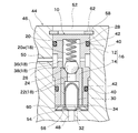
- FIG. 1 is a cross-sectional view showing one embodiment of a mounting means for a housing and a check valve having a fluid passage according to the present invention therein.
- the present invention can be applied not only to fuel but also to various fluids.
- the check valve 10 in this embodiment has a casing 16 formed by combining a main member 12 and a seat member 14, and a fluid communication passage 18 having two openings is formed in the casing 16.
- One of the fluid communication passages 18 having the two openings is in communication with an upstream fluid passage 48 of a housing 46 (described later) provided with a fluid passage described later, and the other is provided with a fluid passage described later.
- the casing 16 communicating with the downstream fluid passage 50 of the provided housing 46 is composed of two members of the main member 12 and the sheet member 14, but the outer surface of the casing 16 is composed of only the main member 12. It may be.
- the main member 12 has a bottomed cylindrical shape, and a first space 20 having one end opened therein is formed.
- the sheet member 14 has a cylindrical shape, and a second space 22 having openings at both ends is formed therein.
- a valve seat 24 is formed on one end face of the seat member 14, and the seat member 14 is inserted into the first space 20 of the main member 12 with the valve seat 24 side as a head.
- the main member 12 and the seat member 14 are fixed by known pull-out prevention means at a position where the seat member 14 valve seat 24 is disposed at a substantially intermediate position in the axial direction of the first space 20 of the main member 12.
- the first space 20 of the main member 12 includes an area where the sheet member 14 exists and an area where the sheet member 14 does not exist, and the sheet member 14 does not exist.
- the region be the first space main region 20a.
- the first space main region 20 a communicates with the second space 22 of the sheet member 14.
- the first space main region 20 a of the main member 12 and the second space 22 of the sheet member 14 constitute a part of the fluid communication passage 18.
- a ball valve (valve element) 26 for contacting the valve seat 24 and a spring 28 as a biasing means for seating the ball valve 26 on the valve seat 24.
- a filter 30 for removing bubbles (air and vapor) and foreign matters mixed in the fuel flowing into the check valve 10.
- An annular filter holding member 34 is attached to the same surface 32 of the main member 12 and the sheet member 14 so as to hold the filter 30 inside the second space 22 of the sheet member 14 so as not to come out. Note that the filter holding member 34 can be omitted if the filter 30 attached to the inside of the second space 22 of the sheet member 14 is elastic and cannot be removed from the second space 22 of the sheet member 14. .
- the ball valve 26 is accommodated in the first space main region 20a so as to be movable in the axial direction.
- the ball valve 26 is seated on the valve seat 24 when the engine is stopped by a spring 28 contracted along the axial direction in the first space main region 20a. While the ball valve 26 is seated on the valve seat 24, the first space main region 20a and the second space 22 of the seat member 14 are blocked by the ball valve 26, and the fluid communication passage 18 of the check valve 10 is closed. Has been.
- the fluid pressure in the second space 22 of the seat member 14 overcomes the urging force of the spring 28 that causes the ball valve 26 to be seated on the valve seat 24, causing the ball valve 26 to move away from the valve seat 24. As a result, the fluid communication passage 18 of the check valve 10 is opened.
- annular recess 36 that goes around the outer wall is formed, and the annular recess 36 and the first space main region 20 a inside the main member 12 are connected by a through hole 38.
- the through hole 38 and the annular recess 36 constitute a part of the fluid communication passage 18.
- two O-ring grooves 40 that make a round around the outer wall of the main member 12 are formed in front and rear positions in the axial direction of the position of the annular recess 36.
- An O-ring 42 is attached to each.
- the check valve 10 having the above configuration is attached to a housing 46 of a device 44 (machine such as an engine or a pump) provided with a fluid passage.
- the housing 46 is a housing of “a member having a fluid passage formed therein” or “a machine such as an engine or a pump having a fluid passage therein”.
- an upstream fluid passage 48 for introducing fluid from a fuel tank (not shown) and a downstream fluid passage 50 for sending fluid to an engine or the like (not shown) are formed in the housing 46.
- a housing space 52 is further formed in the housing 46 from the outer wall to the inside, and the housing space 52 communicates with the upstream fluid passage 48 and the downstream fluid passage 50.
- the check valve 10 is inserted into the housing space 52 formed in the housing 46.
- an annular wave washer 54 as an elastic member is put in the housing space 52, and then the check is made in the housing space 52.
- the wave washer 54 as an elastic member is an annular O-ring that meanders up and down in the height direction, and a central space is a hole through which a fluid can pass.
- the wave washer 54 and the check valve 10 are put in the receiving space 52 and the check valve 10 is pressed toward the wave washer 54, the wave washer 54 is compressed and deformed in the insertion direction (axial direction). , Its height is lowered. On the other hand, when the pressing force is no longer applied to the wave washer 54, its height returns to its original height due to the repulsive force.
- the annular wave washer 54 is in contact with the bottom surface 56 located on the back side of the accommodation space 52 and the other side is an annular filter holding member 34 (insertion tip of the housing 24). Part).
- the wave washer 54 Since the wave washer 54 is interposed between the bottom surface 56 of the accommodation space 52 and the insertion tip of the housing 24, the wave washer 54 is vertically disposed in the accommodation space 52 between the bottom surface 56 and the insertion tip of the check valve 10. A gap space 60 corresponding to the height in the direction is generated.
- the gap space 60 constitutes a part of the fluid communication path 18.
- an annular groove 58 that makes a round of the inner wall surface is formed near the opening of the housing space 52.
- a clip 62 that is a retaining member is fitted and mounted in the groove 58.
- the clip 62 is a C-shaped elastic metal plate (so-called a C-ring) having a size that fits in the annular groove 58 and has elasticity in the circumferential direction.
- the C-shaped inner edge of the clip 62 is sized to protrude inward in the radial direction of the receiving space 52.
- the clip 62 and the groove 58 which are the retaining members, constitute a slip-out preventing means.
- the wave washer 54 When the check valve 10 is attached to the housing space 52 of the housing 46, the wave washer 54 is first inserted into the housing space 52 of the housing 46, and then the check valve 10 (with the filter holding member 34 attached) is inserted. insert.
- the annular wave washer 54 When the filter holding member 34 is not attached to the check valve 10, the annular wave washer 54 is first inserted into the accommodation space 52 of the housing 46, and then the annular filter holding member 34 is inserted. Turn on check valve 10. In a state where the wave washer 54 and the check valve 10 are placed in the housing space 52 of the housing 46, the position of the rear end portion in the insertion direction of the casing 16 (main member 12) is located at the same height as the opening of the groove 58. 58, the clip 62 cannot be fitted.
- the check valve 10 is pressed toward the back side (the bottom surface 56 side) of the accommodation space 52 of the housing 46. Since the wave washer 54 can be displaced in the height direction, when the check valve 10 is pressed in the axial direction, the wave washer 54 is compressed and its height is lowered, and the check valve 10 is lowered in the bottom surface 56 of the accommodation space 52. Move towards the side. As the check valve 10 moves toward the bottom surface 56 side of the accommodation space 52 while compressing the wave washer 54, the circumferential opening of the groove 58 covered with the rear end of the insertion of the check valve 10 is exposed, and the groove In this state, the clip 62 can be attached to the groove 58. When the wave washer 54 is compressed and its height is lowered, the wave washer 54 accumulates an elastic force, that is, a repulsive force due to the compression.
- the check valve 10 When the pressing force applied to the check valve 10 is removed after the clip 62 is attached to the groove 58, the check valve 10 is applied with a force in the direction of coming out of the accommodating space 52 due to the repulsive force of the wave washer 54 that has been compressed. It is done. However, the inserted rear end of the check valve 10 abuts on the clip 62 attached to the groove 58, and the check valve 10 is prevented from jumping out from the accommodation space 52. In a state where the check valve 10 is in contact with the clip 62, the wave washer 54 is set so that a repulsive force due to compression remains (a state where the height of the wave washer is reduced by being compressed) is maintained. .
- the prevention means for preventing the check valve 10 from coming out of the accommodating space 52 is preferably composed of a groove 58 and a clip 62 which is a retaining member fitted into the groove 58. However, it is not limited to this configuration.
- the check valve 10 In a state where the check valve 10 is mounted in the housing space 52 of the housing 46 by the escape prevention means, the check valve 10 is held in the housing 46 without coming out of the housing space 52. In this state, a repulsive force is applied to the wave washer 54. In this state, the upstream fluid passage 48 of the housing 46 further communicates with the second space 22 of the seat member 14 via the gap space 60 in which the wave washer 54 in the check valve 10 is disposed. On the other hand, the downstream fluid passage 50 of the structure 44 communicates with the annular recess 36 formed in the main member 12 of the check valve 10, and the inner fluid of the main member 12 is connected to the annular recess 36 and the through hole 38. One space main area 20a is communicated.
- the ball valve 26 collides with the valve seat 24 vigorously by the biasing force of the spring 28.
- the vibration and impact of the ball valve 26 colliding with the valve seat 24 in the check valve 10 are caused by the wave washer 54 provided between the insertion tip of the check valve 10 and the bottom surface 56 of the housing space 52 of the housing 46. Absorbed. That is, the shock caused by the collision between the ball valve 26 and the valve seat 24 can be mitigated by the wave washer 54, and the deformation of the valve seat 24 due to the collision of the ball valve 26 can be prevented.
- valve seat 24 since the deformation of the valve seat 24 can be prevented, a good sealing property between the ball valve 26 and the valve seat 24 can be ensured over a long period of time, and the stability of the fluid in the fluid communication passage 18 can be secured. The flow rate and fluid pressure can be maintained. Further, since the wave washer 54 elastically absorbs the vibration and shock in the axial direction of the check valve 10 with respect to the housing 46, the check valve 10 can be prevented from rattling in the housing space 52 of the housing 46. .
- Patent Document 1 a plate separate from the pump is used to hold the fuel check valve between the pump housing and the plate (preventing the fuel check valve from coming off). Therefore, a female screw portion for fixing the plate to the pump housing is formed.
- the clip 62 having elasticity in the circumferential direction is fitted into the groove 58 formed in the accommodation space 52 to prevent the check valve 10 from coming out of the accommodation space 52. Therefore, in this invention, it is not necessary to provide the internal thread part for screwing together with a volt
- the casing 16 of the check valve 10 can be thinned, and the diameter of the fluid communication passage 18 formed in the check valve 10 can be increased.
- the increase in the diameter of the fluid communication passage 18 leads to an increase in the flow rate, so that a sufficient opening area can be obtained with a small lift amount without the ball valve 26 being lifted greatly, and the fluid flow rate required at the time of starting. Can be secured. Therefore, the rising flow rate immediately after the valve opening, which has been a problem in the past, can be increased.
- the screw part male screw part
- the screw part is not provided in the casing 16 of the check valve 10
- the size can be reduced (especially the overall length of the check valve 10 can be shortened) or when assembling It is possible to eliminate the possibility of the occurrence of foreign matter from the screw portion.
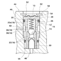
- FIG. 2 is a sectional view showing another embodiment of the fuel check valve according to the present invention.
- an annular wave washer 54 is provided on the inner side of the housing space 52 of the housing 46, and then the check valve 10 is inserted into the housing space 52 of the housing 46.
- the gap space 60 including the annular wave washer 54 is formed on the back side of the accommodation space 52.
- the fluid is agitated by the wave washer 54, and there is a possibility that bubbles (air or vapor) are generated or the fluid is retained.
- the wave washer 54 that is an elastic member is not provided in the back side of the housing space 52 of the housing 46.
- the check valve 10 is inserted into the innermost side of the accommodation space 52 of the housing 46, and then the wave washer 54 that is an elastic member is inserted into the accommodation space 52 of the housing 46.
- the wave washer 54 is positioned at the opening of the groove 58 and the clip 62 cannot be attached to the groove 58 in a state in which no external force is applied to the wave washer 54.
- the wave washer 54 is pressed in the axial direction, the height of the wave washer 54 is lowered and the opening of the groove 58 is exposed.
- the clip 62 can be attached to the groove 58 when the opening of the groove 58 is exposed.
- the wave washer 54 which is an elastic member, is compressed in the vertical direction between the rear end of the check valve 10 and the clip 62 and is elastically deformed ( Sandwiched in a state where the height is lowered).
- the wave washer 54 is disposed outside the fluid communication passage 18 passing through the inside of the check valve 10, and the clearance space 60 as in the first embodiment is formed inside the accommodation space 52. Absent. Therefore, the generation of bubbles in the gap space 60 can be eliminated. Further, since the fuel does not directly touch the wave washer 54, the durability and reliability of the wave washer 54 itself are improved.
- the second embodiment also has the same effect as the first embodiment.
- FIG. 3 is a sectional view showing still another embodiment (embodiment 3) of the fuel check valve according to the present invention.
- the clip 62 and the groove 58 used in the first and second embodiments are different.
- a cylindrical protrusion 64 that protrudes outward from the outer surface is formed integrally with the housing 46 around the position where the accommodation space 52 is formed on the outer surface of the housing 46 of the structure 44.
- Two insertion holes 68 for inserting and fitting the pins 66 are formed in the cylindrical projecting portion 64 in a direction perpendicular to the axial direction of the accommodation space 52.
- a pin 66 as a retaining member is inserted into the two insertion holes 68.
- the wave washer 54 as an elastic member is first put in the storage space 52, and then the check valve 10 is put in the storage space 52.
- the insertion rear end of the check valve 10 is positioned at the linear position connecting the two insertion holes 68 in the accommodation space 52, and the pin 66 has two pieces. It cannot be inserted into the insertion hole 68.
- the check valve 10 is pressed toward the inner side of the accommodating space 52 to compress the wave washer 54, and then a pin 66 is inserted into the two insertion holes 68. Removal from the accommodation space 52 can be prevented.
- the third embodiment has the same effect as the first embodiment.
- An accommodation space 52 is formed in a housing 46 of a pump such as a fuel pump, the check valve 10 is inserted into the accommodation space 52, a fluid passage discharged from the pump chamber of the pump is an upstream fluid passage 48, and an upstream fluid
- the downstream fluid passage 50 discharged through the accommodation space 52 communicating with the passage 48 may be connected to another pipe.
- a fluid passage through which a fluid passes is provided inside the engine housing, a housing space is formed in a part of the fluid passage, the check valve 10 is inserted into the housing space 52, and the fluid discharged from a fuel pump or the like is checked valve 10 may be the upstream fluid passage 48 and the passage through which the fluid discharged from the check valve 10 passes may be the downstream fluid passage 50.
Landscapes
- Engineering & Computer Science (AREA)
- General Engineering & Computer Science (AREA)
- Mechanical Engineering (AREA)
- Chemical & Material Sciences (AREA)
- Combustion & Propulsion (AREA)
- Check Valves (AREA)
- Fuel-Injection Apparatus (AREA)
- Safety Valves (AREA)
Abstract
弁座の変形を防止して弁体と弁座との閉鎖性を確保し、流体通路を内部に備えたハウジングに対するチェックバルブのガタツキを防止し、始動時における必要な流体流量を確保することができる流体通路を内部に備えたハウジングとチェックバルブとの取付け手段を提供する。 流体通路を内部に備えたハウジング46の収容空間52にチェックバルブ10と波ワッシャ54とを入れ、抜け出し防止手段58,62で収容空間52内からチェックバルブ20と波ワッシャ54が抜け出さないようにする。チェックバルブ10と波ワッシャ54とを収容空間52内に取付けた状態においては、波ワッシャ54に反発力が加えられている状態とする。この波ワッシャ54に、チェックバルブ10の弁作動による振動が吸収され、弁座24への衝撃が減少すると共に、ハウジング46とチェックバルブ10との間に発生するガタツキを防止することができる。
Description
本発明は、流体通路を内部に備えたハウジングへのチェックバルブの取付け手段に関するものである。
従来から、流体通路を内部に備えたエンジンや燃料ポンプ等の装置(機械)のハウジングには、その燃料通路を開閉すると共に、料通路内の燃料の逆流を防止するための燃料用チェックバルブが取付けられている。例えば特許文献1には、燃料ポンプとその燃料ポンプに取付ける燃料用チェックバルブの従来構造が示されており、図4にその従来構造を示す。
燃料ポンプ70のケーシング72には、その内部に、燃料タンク(図示せず)からの燃料が導入される上流側燃料通路74と、エンジン(図示せず)へ燃料を供給する下流側燃料通路76と、それら上流側燃料通路74と下流側燃料通路76とを連絡するものであってケーシング72の外面から内部に向けて穿設される収容空間78とが形成されている。燃料用チェックバルブ80は、燃料ポンプ70の収容空間78内に挿入されて、その挿入先端部を収容空間78内の底面82に当接させ、その後、燃料用チェックバルブ80を燃料ポンプ70のケーシング72から抜け出さないように、抜け出し防止手段によって燃料ポンプ70に燃料用チェックバルブ80を固定させている。その抜け出し防止手段については後述する。
燃料用チェックバルブ80は、主部材84とシート部材86とからなるボディ88を有し、そのボディ88内に2箇所に開口する燃料連絡通路90が形成されている。燃料用チェックバルブ80が燃料ポンプ70に取付けられた状態では、燃料連絡通路90の一方の開口部は上流側燃料通路74と連絡し、燃料連絡通路90の他方の開口部は下流側燃料通路76と連絡するよう設定されている。シート部材86の一端には弁座92が設けられており、その弁座92は燃料用チェックバルブ80の燃料連絡通路90の途中に位置している。燃料連絡通路90の途中には、燃料連絡通路90を開閉するためのボール弁94と、そのボール弁94を弁座92に着座する方向に付勢するスプリング96と、が備えられている。
このような構成の燃料用チェックバルブ80においては、エンジン停止時にスプリング96の付勢力によってボール弁94が弁座92に着座して燃料連絡通路90が閉鎖され、上流側燃料通路74と下流側燃料通路76とが遮断される。一方、エンジン駆動時には、上流側燃料通路74の燃料圧が高くなって、その燃料圧がスプリング96に抗してボール弁94を弁座92から離して燃料連絡通路90が開放され、上流側燃料通路74と下流側燃料通路76とが連絡される。
燃料ポンプ70のケーシング72には、収容空間78の位置を中心としてその周辺に複数の雌螺子部98が設けられている。燃料ポンプ70のケーシング72には、雌螺子部98に合致した位置に螺子部より大径の穴100を形成したプレート102が取り付けられるもので、プレート102の穴100をケーシング72の雌螺子部98の位置に合わせて、プレート102をケーシング72に接合させる。その後、雄螺子104をプレート102の穴100から挿入して、雄螺子104とケーシング72の雌螺子部98とを螺合させることで、燃料ポンプ70のケーシング72にプレート102を固定させる。収容空間78に挿入した燃料用チェックバルブ80は、挿入後端部がケーシング72に固定されたプレート102と接触し、挿入先端部は収容空間78の底面82に接触するので、燃料用チェックバルブ80はケーシング72とプレート102とで挟持される。この結果、燃料用チェックバルブ80の収容空間78からの抜け出しが防止されると共に、収容空間78内での燃料用チェックバルブ80のガタつきが防止される。
この特許文献1では、燃料ポンプ70のケーシング72に形成される雌螺子部98と、燃料用チェックバルブ80の抜け出しとガタつきとを防止するためのプレート102と、プレート102をケーシング72の雌螺子部98に螺合するための雄螺子104とで、燃料用チェックバルブ80の燃料ポンプ70への抜け出し防止手段が構成される。この抜け出し防止手段によって、収容空間78からの燃料用チェックバルブ80の抜け出しが防止され、収容空間78内での燃料用チェックバルブ80のガタつきが防止される。
燃料用チェックバルブと燃料ポンプとを固定する手段について、特許文献1とは別の構成のものが特許文献2に示されている。特許文献2では、燃料ポンプのケーシングの収容空間の内壁面に雌螺子部を形成すると共に、燃料用チェックバルブの外壁面に雄螺子部を形成する。この雌螺子部と雄螺子部とを螺合することによって、燃料ポンプと燃料用チェックバルブとが固定される。なお、この特許文献2にける燃料用チェックバルブの構造は、特許文献1の燃料用チェックバルブの構造と同じである。
特許文献1では、燃料ポンプ70と燃料用チェックバルブ80との抜け出し防止手段として、燃料ポンプ70のケーシング72に、収容空間78の位置を中心としたその周辺に、プレート102を固定するための雌螺子部98を複数個設けている。複数の雌螺子部98をケーシング72に形成するので、燃料ポンプ70のケーシング72は大きいものとなる欠点があった。特許文献1に示す燃料用チェックバルブ80は、プレート102と収容空間78の底面82との間に挟持固定されるため、ボール弁94の弁座92への衝撃が長期にわたって燃料用チェックバルブ80と燃料ポンプ70のケーシング72との固定箇所に及び、燃料用チェックバルブ80と燃料ポンプ70のケーシング72の間に、ガタツキが発生するという欠点があった。また、燃料用チェックバルブ80と燃料ポンプ70のケーシング72とが強固に固定されているので、ボール弁94の弁座92への衝撃が和らげられる箇所が無く、ボール弁94の弁座92への長期にわたる衝撃によって弁座92が磨耗し、弁の閉鎖性が損なわれるおそれがあった。
一方、特許文献2では、燃料用チェックバルブの外壁面に雄螺子部を形成するものである。外壁面に雄螺子部を形成する燃料用チェックバルブでは、燃料用チェックバルブのケーシングの外径の大きさが制限される場合に、燃料用チェックバルブの外壁面に形成される雄螺子部の高さ分だけ、燃料用チェックバルブのケーシングの外径を大きくしなければならない。外径の大きさが制限されるものにおいて、燃料用チェックバルブのケーシングの外径が大きくすると、燃料連絡通路の内径やボール弁の直径を小さくせざるを得なくなる。燃料連絡通路の内径が小さくなると、エンジンに供給できる燃料流量が少なくなり、始動時の必要な燃料供給量が得られなくなるという欠点があった。
本発明は、上記の問題点に鑑みて為されたものであり、弁座の変形を防止して弁体と弁座との閉鎖性を確保し、流体通路を内部に備えたハウジングに対するチェックバルブのガタツキの発生を防止し、始動時における必要な流体流量を確保することができる流体通路を内部に備えたハウジングへのチェックバルブの取付け手段を提供することを目的とする。
上記課題を解決するため、本発明に係る流体通路を内部に備えたハウジングとチェックバルブとの取付け手段は、ケーシングと、前記ケーシング内に形成される流体連絡通路と、前記流体連絡通路の途中を開閉するための弁体と、前記弁体が着座するための弁座を備えたシート部材と、前記弁体を前記弁座に着座させる方向に付勢させるための付勢手段とを有するチェックバルブを、上流側流体通路と下流側流体通路とを内部に形成し、前記上流側流体通路と前記下流側流体通路との両方と連絡する収容空間とを有するハウジングに取り付けるものであって、前記チェックバルブを前記ハウジングの前記収容空間に挿入して、前記チェックバルブを前記ハウジングに抜け出し防止手段で取付けるハウジングとチェックバルブとの取付け手段において、押圧力によって伸縮する弾性部材を前記チェックバルブと共に前記収容空間内に入れ、前記抜け出し防止手段で前記チェックバルブと前記弾性部材とを前記ハウジングの収容空間から抜け出るのを防止し、前記チェックバルブと前記弾性部材とが前記収容空間から抜け出るのを防止した状態では、前記弾性部材に圧縮による反発力が与えられていることを特徴とするものである。本発明は、前記弾性部材を前記チェックバルブの前記収容空間の挿入後端部と前記抜け出し防止手段との間に配置したことを特徴とするものである。本発明は、前記弾性部材を前記収容空間の底面と前記チェックバルブの前記収容空間の挿入先端部との間に配置したことを特徴とするものである。本発明は、前記ハウジングが、ポンプまたはエンジンのいずれか一方であり、前記ポンプハウジングまたはエンジンハウジングのいずれか一方に前記チェックバルブを挿入する前記収容空間を形成したことを特徴とするものである。本発明は、前記抜け出し防止手段が、前記流体通路を内部に備えた前記ハウジングの前記収容空間の内周面に形成される環状の溝と、前記溝に嵌合させるものであって周方向に弾性力を有する抜止部材とから成り、前記抜止部材が前記溝に嵌合した状態では、前記抜止部材の一部が前記収容空間の内部に突出して前記チェックバルブと前記弾性部材とを前記収容空間内に保持することを特徴とするものである。本発明は、前記抜け出し防止手段が、前記流体通路を内部に備えた前記ハウジングにおける前記収容空間の形成位置の近傍の外面に形成される突出部と、前記突出部に形成される穴と、前記穴に挿通されるピンとから成り、前記穴に前記ピンを取り付けた状態では前記チェックバルブの挿入後端部か前記弾性部材かのいずれかが前記ピンに接触して前記チェックバルブと前記弾性部材とを前記収容空間内に保持することを特徴とするものである。本発明は、前記弾性部材を波ワッシャとすることを特徴とするものである。
本発明に係る流体通路を内部に備えたハウジングとチェックバルブとの取付け手段によれば、チェックバルブは弾性部材による反発力が与えられた状態で収容空間内に保持されるので、チェックバルブで発生する弁体と弁座との衝突による衝撃を緩和でき、弁座の変形を好適に防止することができる。弁座の変形が防止されることから、長期に渡って弁体と弁座とのシール性を確保することができる。また、収容空間内に備えられるチェックバルブの振動や衝撃が弾性部材によって好適に吸収されるので、流体通路を内部に備えた構造物に対するチェックバルブのガタツキの発生を防止することができる。
また、本発明に係る流体通路を内部に備えたハウジングとチェックバルブとの取付け手段によれば、収容空間に形成した溝に例えばCリング等の抜止部材を取り付けて、チェックバルブが流体通路を内部に備えたハウジングの収容空間内から抜け出るのを防止する。従って、特許文献1のようにポンプのハウジングに雌螺子部を設ける必要が無く、また特許文献2のようにチェックバルブのボディに雄螺子部を形成する必要がない。この結果、流体通路を内部に備えたハウジングの増大化を必要とせず、しかもチェックバルブのボディの薄肉化が可能となり、その結果としてチェックバルブのボディ内の流体連絡通路の大径化と、弁体(ボール弁)の大径化を図ることができる。この流体通路の大径化は流量の大容量化につながるので、弁体を大きくリフトさせなくても僅かなリフト量で十分な通路面積を確保することができ、従来問題であった開弁直後の立ち上がり時の必要流量を確保することができる。さらに、チェックバルブのボディに雄螺子部を設けないことにより、チェックバルブのボディへのねじれや伸びに対する強度確保が不要となり、アルミや真鍮等の安価で加工性の良い材料を使えることが可能となって、材料費や加工費を削減することができる。その他に、組付け時に螺子部から収容空間内への異物混入のおそれを無くすことができる。
また、弾性部材をチェックバルブの挿入後端部と抜止部材との間に配置すれば、チェックバルブの挿入先端部が流体通路を内部に備えたハウジングの収容空間の底面と接触して、チェックバルブの挿入先端部と流体通路を内部に備えたハウジングの収容空間の底面との間に、弾性部材を備えるための隙間空間が設けられることが無くなる。隙間空間が設けられることはないので、チェックバルブの流体連絡通路に導入される流体が、隙間空間で攪拌される気泡(空気やベーパー)が発生することを無くし、隙間空間への流体の滞留を無くして、流体流量や流体圧を安定させることができる。また、弾性部材が流体に直接触れることはなくなるので、弾性部材自体の耐久性や信頼性も向上する。
10 チェックバルブ
12 主部材
14 シート部材
16 ケーシング
18 流体連絡通路
20 第一空間
20a 第一空間主領域
22 第二空間
24 弁座
26 ボール弁
28 スプリング
34 フィルタ保持部材
44 流体通路を内部に備えた装置
46 ハウジング
48 上流側流体通路
50 下流側流体通路
52 収容空間
54 波ワッシャ
58 溝
60 隙間空間
62 クリップ
64 筒状突出部
66 ピン
68 挿入穴
12 主部材
14 シート部材
16 ケーシング
18 流体連絡通路
20 第一空間
20a 第一空間主領域
22 第二空間
24 弁座
26 ボール弁
28 スプリング
34 フィルタ保持部材
44 流体通路を内部に備えた装置
46 ハウジング
48 上流側流体通路
50 下流側流体通路
52 収容空間
54 波ワッシャ
58 溝
60 隙間空間
62 クリップ
64 筒状突出部
66 ピン
68 挿入穴
本発明は、流体通路を内部に備えたハウジングにチェックバルブを取付ける取付け手段に係るものである。
以下、本発明を図面に基づいて説明する。図1は、本発明に係る流体通路を内部に備えたハウジングとチェックバルブとの取付け手段の一実施例を示す断面図である。本発明は、燃料だけでなく各種の流体に適用することができるものである。本実施例におけるチェックバルブ10は、主部材12とシート部材14とを組み合わせて成るケーシング16を有し、そのケーシング16に、2個の開口部を有する流体連絡通路18が形成される。この2個の開口部を有する流体連絡通路18は、一方は後述する流体通路を内部に備えたハウジング46(後述する)の上流側流体通路48と連絡し、他方は後述する流体通路を内部に備えたハウジング46の下流側流体通路50と連絡するケーシング16は、主部材12とシート部材14との2個の部材から構成されるとしたがケーシング16の外側表面は、主部材12のみから構成されるものであっても良い。
主部材12は有底円筒形状をしており、内部には一端が開口する第一空間20が形成されている。シート部材14は円筒形状をしており、その内部には両端が開口する第二空間22が形成されている。シート部材14の一方側の端面には弁座24が形成されており、その弁座24側を先頭としてシート部材14が主部材12の第一空間20内に挿入される。シート部材14弁座24の位置が、主部材12の第一空間20の軸方向のほぼ中間位置に配置した位置で、主部材12とシート部材14とが既知の抜け出し防止手段で固定される。主部材12とシート部材14とが固定された状態では、主部材12の第一空間20は、シート部材14が存在する領域とシート部材14が存在しない領域とから成り、シート部材14が存在しない領域を第一空間主領域20aとする。この第一空間主領域20aは、シート部材14の第二空間22と連絡する。主部材12の第一空間主領域20aとシート部材14の第二空間22とは、前記流体連絡通路18の一部を構成する。
第一空間主領域20aの内部には、弁座24に接触するためのボール弁(弁体)26と、そのボール弁26を弁座24に着座させるための付勢手段としてのスプリング28とが備えられている。シート部材14の第二空間22の内部には、チェックバルブ10内に流入してくる燃料の中に混在する気泡(空気やベーパー)や異物を除去するためのフィルタ30が備えられている。主部材12の第一空間20内にシート部材14を挿入固定した状態では、主部材12の第一空間20の開口部側の端面と、筒状のシート部材14の挿入後端部の端面とを同一面32とするのが望ましいが、必ずしもそれに限るものではない。主部材12とシート部材14の同一面32には、フィルタ30がシート部材14の第二空間22内から抜け出さないようにその内部に保持するための環状のフィルタ保持部材34が取り付けられる。なお、シート部材14の第二空間22の内部に取付けられるフィルタ30は、弾力性があってシート部材14の第二空間22から外れないものとすれば、フィルタ保持部材34を省略することができる。
ボール弁26は、第一空間主領域20a内に軸方向に移動可能な状態で収容されている。ボール弁26は、第一空間主領域20a内に軸方向に沿って縮設されているスプリング28によって、エンジン停止時には弁座24に着座させられる。ボール弁26が弁座24に着座している間は、ボール弁26によって、第一空間主領域20aとシート部材14の第二空間22とは遮断され、チェックバルブ10の流体連絡通路18は閉鎖されている。一方、エンジン駆動時には、シート部材14の第二空間22の流体圧が、ボール弁26を弁座24に着座させるスプリング28の付勢力に打ち勝って、ボール弁26を弁座24から離れさせる。これによって、チェックバルブ10の流体連絡通路18が開かれる。
主部材12の外壁には、その外壁を一周する環状凹部36が形成され、その環状凹部36と主部材12の内部の第一空間主領域20aとは貫通穴38によって連絡されている。貫通穴38と環状凹部36は、前記流体連絡通路18の一部を構成する。主部材12の外壁には、環状凹部36の位置の軸方向の前後位置に、主部材12の外壁を一周するOリング溝40が2箇所形成されており、そのOリング溝40の内部には夫々Oリング42が取り付けられている。
上記構成のチェックバルブ10は、流体通路を内部に備えた装置44(エンジンやポンプ等の機械)のハウジング46に取り付けられる。以後、ハウジング46は、「流体通路を内部に形成した部材」や、「流体通路を内部に備えたエンジンやポンプ等の機械」のハウジングとする。ハウジング46の内部には、例えば燃料タンク(図示せず)からの流体を導入する上流側流体通路48と、例えばエンジン等(図示せず)へ流体を送り出す下流側流体通路50とが形成されている。ハウジング46には更に、外壁から内部に向けて収容空間52が形成され、その収容空間52は上流側流体通路48と下流側流体通路50とに連絡されている。
チェックバルブ10はハウジング46に形成された収容空間52に挿入されるが、実施例1では、先ず収容空間52内に弾性部材としての環状の波ワッシャ54を入れ、その後、収容空間52内にチェックバルブ10を挿入する。弾性部材としての波ワッシャ54は、高さ方向に上下に蛇行した環状のOリングであり、中央の空間は流体が通過できる穴となっている。
収容空間52に波ワッシャ54とチェックバルブ10とを入れた状態でチェックバルブ10に波ワッシャ54側への押圧力がかかると、波ワッシャ54は挿入方向(軸方向)の高さが圧縮変形され、その高さが低くなる。一方、波ワッシャ54に押圧力がかからなくなると、反発力でその高さが、元の高さに戻るものである。チェックバルブ10を収容空間52に挿入した状態では、環状の波ワッシャ54は、一方側が収容空間52の奥に位置する底面56と接触し、他方側が環状のフィルタ保持部材34(ハウジング24の挿入先端部)と接触する。波ワッシャ54は収容空間52の底面56とハウジング24の挿入先端部との間に介在するので、底面56とチェックバルブ10の挿入先端との間の収容空間52には、この波ワッシャ54の縦方向の高さ分だけの隙間空間60が発生する。この隙間空間60は、流体連絡通路18の一部を構成する。
ハウジング46の収容空間52の内壁において、収容空間52の開口部付近に内壁面を一周する環状の溝58が形成されている。この溝58に、抜止部材であるクリップ62を嵌合装着させる。クリップ62は、環状の溝58にちょうど嵌合する大きさのC字形状の弾力性のある金属板(所謂Cリングと呼ばれるもの)であり、周方向に弾力性を有するものである。クリップ62が収容空間52の溝58に取付けられた状態においては、クリップ62のC字形状の内側縁は、収容空間52の半径方向の内側に突出する大きさとなっている。抜止部材であるクリップ62と溝58とで、抜け出し防止手段を構成する。
チェックバルブ10を、ハウジング46の収容空間52に取り付ける場合には、ハウジング46の収容空間52に、最初に波ワッシャ54を挿入し、次にチェックバルブ10(フィルタ保持部材34を取り付けたもの)を挿入する。なお、フィルタ保持部材34がチェックバルブ10に取り付けられていない場合には、ハウジング46の収容空間52に、先に環状の波ワッシャ54を入れ、次に環状のフィルタ保持部材34を入れ、その後にチェックバルブ10を入れる。波ワッシャ54とチェックバルブ10をハウジング46の収容空間52に入れた状態では、ケーシング16(主部材12)の挿入方向後端部の位置が溝58の開口部と同じ高さに位置し、溝58にクリップ62を嵌合できない状態となっている。
この状態において、チェックバルブ10をハウジング46の収容空間52の奥側(底面56側)に向けて押圧する。波ワッシャ54は高さ方向に変位可能であるので、チェックバルブ10が軸方向に押圧されると、波ワッシャ54は圧縮されてその高さが低くなり、チェックバルブ10は収容空間52の底面56側に向けて移動する。チェックバルブ10が波ワッシャ54を圧縮しながら収容空間52の底面56側に移動することで、チェックバルブ10の挿入後端部で覆われていた溝58の円周方向開口部が露出され、溝58にクリップ62を取り付けることが可能な状態となり、その状態で溝58にクリップ62を取り付ける。波ワッシャ54が圧縮されてその高さが低くなると、波ワッシャ54には圧縮されることによる弾性力即ち反発力が蓄積される。
溝58にクリップ62を取付けた後、チェックバルブ10への押圧力を除去すると、圧縮されていた波ワッシャ54の反発力で、チェックバルブ10には収容空間52から外に抜け出る方向の力が加えられる。しかし、チェックバルブ10の挿入後端部が、溝58に取り付けられたクリップ62に当接し、チェックバルブ10が収容空間52から外側への飛び出しが阻止される。チェックバルブ10がクリップ62に当接した状態では、波ワッシャ54には圧縮による反発力が残るように(圧縮されてその高さが低くなっている状態が保たれるように)設定されている。チェックバルブ10の収容空間52からの抜けを防止するための抜け出し防止手段としては、溝58とその溝58に嵌合する抜止部材であるクリップ62とから構成されるのが望ましいが、抜け出し防止手段としてはこの構成に限るものではない。
ハウジング46の収容空間52内にチェックバルブ10が抜け出し防止手段によって取り付けられた状態では、チェックバルブ10は収容空間52内から抜け出ることなくハウジング46に保持される。この状態では、波ワッシャ54には反発力が加えられている。この状態では更に、ハウジング46の上流側流体通路48はチェックバルブ10における波ワッシャ54を配置した隙間空間60を介して、シート部材14の第二空間22と連絡する。一方、構造物44の下流側流体通路50は、チェックバルブ10の主部材12に形成された環状凹部36と連絡し、その環状凹部36と貫通穴38とを介して主部材12の内部の第一空間主領域20aと連絡する。
チェックバルブ10においては、ボール弁26が弁座24に着座する際に、スプリング28の付勢力によってボール弁26が弁座24に勢い良く衝突する。本発明では、チェックバルブ10におけるボール弁26が弁座24に衝突する振動や衝撃が、チェックバルブ10の挿入先端部とハウジング46の収容空間52の底面56との間に備えられる波ワッシャ54で吸収される。即ち、ボール弁26と弁座24との衝突による衝撃を波ワッシャ54で緩和して、ボール弁26の衝突による弁座24の変形を防止することができる。本発明では、弁座24の変形を防止することができるので、ボール弁26と弁座24との良好なシール性を長期に渡って確保することができ、流体連絡通路18内における流体の安定した流量と流体圧とを保持することができる。また、波ワッシャ54によって、ハウジング46に対するチェックバルブ10の軸方向の振動や衝撃を弾性的に吸収しているので、ハウジング46の収容空間52内でのチェックバルブ10のガタツキも防止することができる。
特許文献1では、ポンプとは別体のプレートを用いて、ポンプのハウジングとプレートとで燃料用チェックバルブを挟持する(燃料用チェックバルブの抜け出しを防止する)ものである。そのため、ポンプのハウジングにプレートを固定するための雌螺子部を形成していた。これに対して本発明では、周方向に弾力性を有するクリップ62を収容空間52に形成した溝58に嵌合することで、チェックバルブ10の収容空間52からの抜け出しを防止するものである。よって、本発明では、特許文献1のようなポンプのハウジングにボルトと螺合するための雌螺子部を設けなくても良い。
本発明では、特許文献2のように、チェックバルブのケーシングの外壁に雄螺子部を設けなくても良いのである。よって、本発明では、チェックバルブ10のケーシング16の薄肉化が可能となり、チェックバルブ10に形成する流体連絡通路18の大径化を図ることができる。この流体連絡通路18の大径化は流量の大容量化につながるので、ボール弁26を大きくリフトさせなくても僅かなリフト量で十分な開口面積を得ることができ、始動時に必要な流体流量を確保することができる。よって、従来問題であった開弁直後の立ち上がりの流量を大きくすることができる。本発明では更に、チェックバルブ10のケーシング16に螺子部(雄螺子部)を設けないようにしたので、チェックバルブ10のケーシング16のねじれや伸びに対する強度確保が不要となり、アルミや真鍮等の安価で加工性の良い材料を使えることになり、材料費や加工費を削減することができる。その他にも、特にチェックバルブ10の縦方向(ハウジング24の収容空間52の挿入方向)の部品配置の制約が少なくなるのでサイズダウン(特にチェックバルブ10の全長の短縮)を図れたり、組付け時のネジ部からの異物発生のおそれを無くしたりすることができる。
次に、本発明に係る燃料用チェックバルブの他の実施例について説明する。図2は、本発明に係る燃料用チェックバルブの他の実施例を示す断面図である。図1に示すチェックバルブ10では、ハウジング46の収容空間52の奥側に環状の波ワッシャ54を備え、その後、ハウジング46の収容空間52内にチェックバルブ10を挿入していた。この実施例1では、収容空間52の奥側に環状の波ワッシャ54を備える隙間空間60が形成されていた。しかし、この隙間空間60では、流体が波ワッシャ54によって攪拌されて気泡(空気やベーパー)の発生や流体の滞留が生じるおそれがあった。
図2に示す実施例2では、弾性部材である波ワッシャ54は、ハウジング46の収容空間52の奥側に備えないものである。この実施例2では、ハウジング46の収容空間52の一番奥側にチェックバルブ10を挿入し、その後、弾性部材である波ワッシャ54をハウジング46の収容空間52に入れる。波ワッシャ54をハウジング46の収容空間52に入れた状態では、波ワッシャ54に外力がかからない状態では、溝58の開口部に波ワッシャ54が位置して溝58にクリップ62を取り付けることができない状態に設定される。波ワッシャ54を軸方向に押し付けると、波ワッシャ54の高さが低くなり、溝58の開口部が露出される。溝58の開口部が露出されたることで、溝58にクリップ62を取り付けることができる。
溝58にクリップ62を取り付けた状態では、弾性部材である波ワッシャ54は、チェックバルブ10の挿入後端部とクリップ62との間で、上下方向に圧縮されて弾性変形が加えられた状態(高さが低くなった状態)で挟持される。この実施例2においては、波ワッシャ54は、チェックバルブ10の内部を通る流体連絡通路18の外に配置され、収容空間52の内部に実施例1のような隙間空間60が形成されることはない。従って、隙間空間60での気泡の発生そのものを無くすことができる。また、燃料が波ワッシャ54に直接触れなくなるので、波ワッシャ54自体の耐久性や信頼性も向上する。この実施例2においても、実施例1と同じ効果を有する。
次に、本発明に係る燃料用チェックバルブのさらに他の実施形態について説明する。図3は、本発明に係る燃料用チェックバルブの更に他の実施例(実施例3)を示す断面図である。実施例3においては、チェックバルブ10のハウジング46からの抜け止め防止手段は、実施例1や実施例2で用いたクリップ62と溝58とは異なったものを用いる。実施例3では、構造物44のハウジング46の外面において収容空間52を形成した位置の周囲に、外面より外側に突出する筒状突出部64をハウジング46と一体に形成する。この筒状突出部64において収容空間52の軸方向に対して直角方向に、ピン66を挿入嵌合するための挿入穴68を2個形成する。2個の挿入穴68に、抜止部材であるピン66を挿入する。
この実施例3では、実施例1と同様に、収容空間52に先ず弾性部材である波ワッシャ54を入れ、次に収容空間52にチェックバルブ10を入れる。波ワッシャ54を圧縮する外力が働いていない状態では、収容空間52における2個の挿入穴68を連絡する直線方向位置にはチェックバルブ10の挿入後端部が位置し、ピン66を2個の挿入穴68に挿入させることができない。ここで、チェックバルブ10を収容空間52の奥側に向けて押圧して波ワッシャ54を圧縮させた状態とし、その後2個の挿入穴68にピン66を入れ、このピン66によってチェックバルブ10の収容空間52からの抜けを防止することができる。波ワッシャ54によって、チェックバルブ10がピン66に接触して入る状態においては、波ワッシャ54の弾性力がチェックバルブ10をピン66側に押圧する状態となっているなお、この実施例3においては、ピン66に波ワッシャ54を接触させるようにしても良い。この実施例3においても、実施例1と同じ効果を有する。
燃料ポンプなどのポンプのハウジング46に収容空間52を形成して、チェックバルブ10を収容空間52に挿入し、ポンプのポンプ室からの吐出される流体通路を上流側流体通路48とし、上流側流体通路48と連絡する収容空間52を経て吐出される下流側流体通路50を他の配管と接続しても良い。また、エンジンのハウジング内部に流体が通過する流体通路を備え、流体通路の一部に収容空間を形成し、チェックバルブ10を収容空間52に挿入し、燃料ポンプ等から吐出された流体をチェックバルブ10に供給する通路を上流側流体通路48とし、チェックバルブ10から吐出された流体が通過する通路を下流側流体通路50としても良い。
Claims (7)
- ケーシングと、前記ケーシング内に形成される流体連絡通路と、前記流体連絡通路の途中を開閉するための弁体と、前記弁体が着座するための弁座を備えたシート部材と、前記弁体を前記弁座に着座させる方向に付勢させるための付勢手段とを有するチェックバルブを、上流側流体通路と下流側流体通路とを内部に形成し、前記上流側流体通路と前記下流側流体通路との両方と連絡する収容空間とを有するハウジングに取り付けるものであって、前記チェックバルブを前記ハウジングの前記収容空間に挿入して、前記チェックバルブを前記ハウジングに抜け出し防止手段で取付けるハウジングとチェックバルブとの取付け手段において、押圧力によって伸縮する弾性部材を前記チェックバルブと共に前記収容空間内に入れ、前記抜け出し防止手段で前記チェックバルブと前記弾性部材とを前記ハウジングの収容空間から抜け出るのを防止し、前記チェックバルブと前記弾性部材とが前記収容空間から抜け出るのを防止した状態では、前記弾性部材に圧縮による反発力が与えられていることを特徴とする流体通路を内部に備えたハウジングとチェックバルブとの取付け手段。
- 前記弾性部材を前記チェックバルブの前記収容空間の挿入後端部と前記抜け出し防止手段との間に配置したことを特徴とする請求項1記載の流体通路を内部に備えたハウジングとチェックバルブとの取付け手段。
- 前記弾性部材を前記収容空間の底面と前記チェックバルブの前記収容空間の挿入先端部との間に配置したことを特徴とする請求項1記載の流体通路を内部に備えたハウジングとチェックバルブとの取付け手段。
- 前記ハウジングが、ポンプまたはエンジンのいずれか一方であり、前記ポンプハウジングまたはエンジンハウジングのいずれか一方に前記チェックバルブを挿入する前記収容空間を形成したことを特徴とする請求項1記載の流体通路を内部に備えたハウジングとチェックバルブとの取付け手段。
- 前記抜け出し防止手段が、前記流体通路を内部に備えた前記ハウジングの前記収容空間の内周面に形成される環状の溝と、前記溝に嵌合させるものであって周方向に弾性力を有する抜止部材とから成り、前記抜止部材が前記溝に嵌合した状態では、前記抜止部材の一部が前記収容空間の内部に突出して前記チェックバルブと前記弾性部材とを前記収容空間内に保持することを特徴とする請求項1乃至4のいずれか1項に記載の流体通路を内部に備えたハウジングとチェックバルブとの取付け手段。
- 前記抜け出し防止手段が、前記流体通路を内部に備えた前記ハウジングにおける前記収容空間の形成位置の近傍の外面に形成される突出部と、前記突出部に形成される穴と、前記穴に挿通されるピンとから成り、前記穴に前記ピンを取り付けた状態では前記チェックバルブの挿入後端部か前記弾性部材かのいずれかが前記ピンに接触して前記チェックバルブと前記弾性部材とを前記収容空間内に保持することを特徴とする請求項1乃至4のいずれか1項に記載の流体通路を内部に備えたハウジングとチェックバルブとの取付け手段。
- 前記弾性部材を波ワッシャとすることを特徴とする請求項1乃至6のいずれか1項に記載の流体通路を内部に備えたハウジングとチェックバルブとの取付け手段。
Priority Applications (3)
| Application Number | Priority Date | Filing Date | Title |
|---|---|---|---|
| CN201280012145.2A CN103415732B (zh) | 2011-03-07 | 2012-02-28 | 外壳与止回阀的安装结构和止回阀相对于外壳的安装方法 |
| EP12754876.6A EP2685144A4 (en) | 2011-03-07 | 2012-02-28 | MEANS TO ASSEMBLE A CHECK VALVE IN A HOUSING WITH A FLUID CHANNEL THEREIN |
| US14/003,024 US20130333770A1 (en) | 2011-03-07 | 2012-02-28 | Means for mounting check valve into housing including fluid passage therein |
Applications Claiming Priority (2)
| Application Number | Priority Date | Filing Date | Title |
|---|---|---|---|
| JP2011049273A JP2012184820A (ja) | 2011-03-07 | 2011-03-07 | 流体通路を内部に備えたハウジングへのチェックバルブの取付け手段 |
| JP2011-049273 | 2011-03-07 |
Publications (1)
| Publication Number | Publication Date |
|---|---|
| WO2012121054A1 true WO2012121054A1 (ja) | 2012-09-13 |
Family
ID=46798022
Family Applications (1)
| Application Number | Title | Priority Date | Filing Date |
|---|---|---|---|
| PCT/JP2012/054871 Ceased WO2012121054A1 (ja) | 2011-03-07 | 2012-02-28 | 流体通路を内部に備えたハウジングへのチェックバルブの取付け手段 |
Country Status (5)
| Country | Link |
|---|---|
| US (1) | US20130333770A1 (ja) |
| EP (1) | EP2685144A4 (ja) |
| JP (1) | JP2012184820A (ja) |
| CN (1) | CN103415732B (ja) |
| WO (1) | WO2012121054A1 (ja) |
Cited By (1)
| Publication number | Priority date | Publication date | Assignee | Title |
|---|---|---|---|---|
| ITMI20130128A1 (it) * | 2013-01-29 | 2014-07-30 | Bosch Gmbh Robert | Gruppo di pompaggio per alimentare combustibile, preferibilmente gasolio, da un serbatoio di contenimento ad un motore a combustione interna |
Families Citing this family (17)
| Publication number | Priority date | Publication date | Assignee | Title |
|---|---|---|---|---|
| DE102013215275A1 (de) * | 2013-08-02 | 2015-02-05 | Robert Bosch Gmbh | Kraftstoffhochdruckpumpe, mit einem Auslassventil |
| TWI612000B (zh) * | 2014-03-14 | 2018-01-21 | 新東工業股份有限公司 | 加壓槽、將粉體送入輸送管之送入裝置及其送入方法 |
| CN104007446B (zh) * | 2014-06-12 | 2016-07-06 | 北京华航无线电测量研究所 | 一种共形结构气路防回流吹扫装置 |
| US9915357B1 (en) * | 2015-02-19 | 2018-03-13 | TSI Products, Inc. | Actuator with back pressure valve |
| US10056805B2 (en) * | 2015-10-02 | 2018-08-21 | Hamilton Sundstrand Corporation | Venting generator assemblies |
| DE102015220028A1 (de) * | 2015-10-15 | 2017-04-20 | Robert Bosch Gmbh | Durchflussbegrenzer für einen Injektor |
| JP2018020755A (ja) * | 2016-07-25 | 2018-02-08 | 株式会社アドヴィックス | 負圧式倍力装置用逆止弁 |
| IT201600113109A1 (it) * | 2016-11-09 | 2018-05-09 | Oleodinamica Marchesini S R L | Valvola di blocco perfezionata per cilindro oleodinamico |
| DE102017121443A1 (de) * | 2017-02-13 | 2018-08-16 | ECO Holding 1 GmbH | Rückschlagventil für einen Pleuel einer Brennkraftmaschine mit variabler Verdichtung sowie Pleuel mit einem derartigen Rückschlagventil |
| US10612404B2 (en) * | 2017-05-01 | 2020-04-07 | Senior Ip Gmbh | Joint cover with improved manifold block for duct leak detection system |
| KR102602359B1 (ko) * | 2018-11-22 | 2023-11-16 | 에이치엘만도 주식회사 | 체크밸브 및 이를 포함하는 모듈레이터블록 |
| KR102613628B1 (ko) * | 2019-03-29 | 2023-12-14 | 에이치엘만도 주식회사 | 브레이크 시스템의 체크 밸브 |
| DE102019218400B4 (de) * | 2019-11-27 | 2025-03-27 | Hawe Hydraulik Se | Ventilkegel und Lasthalteventil mit Ventilkegel |
| US11781513B2 (en) * | 2020-01-07 | 2023-10-10 | Hitachi Astemo, Ltd. | Discharge valve mechanism and high-pressure fuel supply pump including the same |
| USD1047080S1 (en) | 2020-04-29 | 2024-10-15 | Ac Avalanche, Llc | Dispenser housing |
| FR3114856B1 (fr) * | 2020-10-06 | 2023-12-29 | Vianney Rabhi | Platine-clapet a microbilles libres |
| JP7836792B2 (ja) * | 2023-08-31 | 2026-03-27 | 株式会社鷺宮製作所 | 圧力調整弁 |
Citations (8)
| Publication number | Priority date | Publication date | Assignee | Title |
|---|---|---|---|---|
| JPS5534036U (ja) * | 1978-08-23 | 1980-03-05 | ||
| JPS62112362U (ja) * | 1985-12-30 | 1987-07-17 | ||
| JPH0246170U (ja) * | 1988-09-22 | 1990-03-29 | ||
| JPH02130478U (ja) * | 1989-04-03 | 1990-10-26 | ||
| JPH0566378U (ja) * | 1992-02-18 | 1993-09-03 | 株式会社イナックス | 定流量弁付き逆止弁 |
| JP2002181231A (ja) * | 2000-12-15 | 2002-06-26 | Tlv Co Ltd | 液体圧送装置 |
| JP3361987B2 (ja) | 1998-02-20 | 2003-01-07 | 三菱電機株式会社 | 逆止弁およびシートバルブ |
| JP2009531577A (ja) | 2006-01-31 | 2009-09-03 | ローベルト ボツシユ ゲゼルシヤフト ミツト ベシユレンクテル ハフツング | 内燃機関に燃料を供給するための高圧ポンプ |
Family Cites Families (25)
| Publication number | Priority date | Publication date | Assignee | Title |
|---|---|---|---|---|
| DE1806409A1 (de) * | 1968-02-26 | 1969-09-04 | Yoshio Kajita | Rueckschlagventil |
| US3583832A (en) * | 1969-05-13 | 1971-06-08 | Lee Co | Booster |
| US3732890A (en) * | 1971-05-28 | 1973-05-15 | Aqua Mec Inc | Unloader valve for air compressor |
| JPS53744Y2 (ja) * | 1973-04-25 | 1978-01-11 | ||
| US3930613A (en) * | 1974-10-18 | 1976-01-06 | Therm-O-Disc Incorporated | Check valve having temperature response |
| US4280529A (en) * | 1979-03-01 | 1981-07-28 | Giancarlo Silvestri | Vented fuel tank cap |
| CA2181671A1 (en) * | 1996-07-19 | 1998-01-20 | Rick Picher | Downhole two-way check valve |
| US5782269A (en) * | 1997-04-14 | 1998-07-21 | Caterpillar Inc. | Soft seal poppet type check valve |
| CN2525323Y (zh) * | 2002-01-24 | 2002-12-11 | 江苏省机电研究所 | 高低压转换阀 |
| DE10214747A1 (de) * | 2002-04-03 | 2003-10-16 | Sasserath & Co Kg H | Ventilanordnung für einen Rohrtrenner |
| CN2592992Y (zh) * | 2002-10-31 | 2003-12-17 | 王心言 | 筒网式过滤单向阀门 |
| US6783337B2 (en) * | 2002-11-13 | 2004-08-31 | Caterpillar Inc | Check valve seal assembly |
| KR20070003882A (ko) * | 2004-02-04 | 2007-01-05 | 가부시키가이샤 코스멕 | 유량제어밸브 및 유량제어밸브 부착 실린더 장치 |
| WO2007016780A1 (en) * | 2005-08-09 | 2007-02-15 | Stackpole Limited | Pressure relief valve |
| ITMI20060037U1 (it) * | 2006-02-01 | 2007-08-02 | Caleffi Spa | Valvola perfezionata di sicurezza per caldaie murali |
| JP2008082261A (ja) * | 2006-09-28 | 2008-04-10 | Matsushita Electric Ind Co Ltd | 密閉型圧縮機 |
| KR100884068B1 (ko) * | 2006-12-07 | 2009-02-19 | 기아자동차주식회사 | 폭발 방지 장치 |
| CN201090797Y (zh) * | 2007-10-12 | 2008-07-23 | 郑家均 | 油管试压控制阀 |
| US8070130B2 (en) * | 2008-01-22 | 2011-12-06 | Fisher Controls International, Llc | Apparatus to bias valve closure members |
| DE102009025355B4 (de) * | 2008-07-02 | 2018-09-06 | Schaeffler Technologies AG & Co. KG | Spannvorrichtung für eine Kette und Überdruckventil |
| US20100032242A1 (en) * | 2008-08-05 | 2010-02-11 | Lin Chung-Chuan | Pressure Relief Device for a Gear Box |
| JP2010116979A (ja) * | 2008-11-13 | 2010-05-27 | Advics Co Ltd | 逆流防止装置 |
| CN201475376U (zh) * | 2009-07-13 | 2010-05-19 | 北京航天动力研究所 | 高压气体迷宫式放空阀 |
| CN201606544U (zh) * | 2010-03-05 | 2010-10-13 | 项勤雄 | 一种止回阀 |
| JP3161835U (ja) * | 2010-05-31 | 2010-08-12 | 菱樹商事株式会社 | 水道連結型スプリンクラーヘッド接続用の継手 |
-
2011
- 2011-03-07 JP JP2011049273A patent/JP2012184820A/ja active Pending
-
2012
- 2012-02-28 WO PCT/JP2012/054871 patent/WO2012121054A1/ja not_active Ceased
- 2012-02-28 CN CN201280012145.2A patent/CN103415732B/zh not_active Expired - Fee Related
- 2012-02-28 US US14/003,024 patent/US20130333770A1/en not_active Abandoned
- 2012-02-28 EP EP12754876.6A patent/EP2685144A4/en not_active Withdrawn
Patent Citations (8)
| Publication number | Priority date | Publication date | Assignee | Title |
|---|---|---|---|---|
| JPS5534036U (ja) * | 1978-08-23 | 1980-03-05 | ||
| JPS62112362U (ja) * | 1985-12-30 | 1987-07-17 | ||
| JPH0246170U (ja) * | 1988-09-22 | 1990-03-29 | ||
| JPH02130478U (ja) * | 1989-04-03 | 1990-10-26 | ||
| JPH0566378U (ja) * | 1992-02-18 | 1993-09-03 | 株式会社イナックス | 定流量弁付き逆止弁 |
| JP3361987B2 (ja) | 1998-02-20 | 2003-01-07 | 三菱電機株式会社 | 逆止弁およびシートバルブ |
| JP2002181231A (ja) * | 2000-12-15 | 2002-06-26 | Tlv Co Ltd | 液体圧送装置 |
| JP2009531577A (ja) | 2006-01-31 | 2009-09-03 | ローベルト ボツシユ ゲゼルシヤフト ミツト ベシユレンクテル ハフツング | 内燃機関に燃料を供給するための高圧ポンプ |
Non-Patent Citations (1)
| Title |
|---|
| See also references of EP2685144A4 |
Cited By (1)
| Publication number | Priority date | Publication date | Assignee | Title |
|---|---|---|---|---|
| ITMI20130128A1 (it) * | 2013-01-29 | 2014-07-30 | Bosch Gmbh Robert | Gruppo di pompaggio per alimentare combustibile, preferibilmente gasolio, da un serbatoio di contenimento ad un motore a combustione interna |
Also Published As
| Publication number | Publication date |
|---|---|
| EP2685144A1 (en) | 2014-01-15 |
| EP2685144A4 (en) | 2014-09-17 |
| US20130333770A1 (en) | 2013-12-19 |
| CN103415732B (zh) | 2015-03-11 |
| CN103415732A (zh) | 2013-11-27 |
| JP2012184820A (ja) | 2012-09-27 |
Similar Documents
| Publication | Publication Date | Title |
|---|---|---|
| WO2012121054A1 (ja) | 流体通路を内部に備えたハウジングへのチェックバルブの取付け手段 | |
| KR100909454B1 (ko) | 유체용 개폐밸브장치 | |
| US9097356B2 (en) | Check valve | |
| JP6099739B2 (ja) | ピストン型燃料ポンプ | |
| JP5677574B2 (ja) | 閉止体を備えるピストンポンプのバルブ | |
| KR100590399B1 (ko) | 역지밸브용 밸브체 | |
| CN106838381B (zh) | 单向阀 | |
| EP1911642A2 (en) | Structure for attaching a vehicle lamp cleaning device | |
| JP2017198386A (ja) | 膨張弁 | |
| EP2759748A1 (en) | Fluid device unit | |
| JP2006029573A (ja) | 圧力緩和構造を備えた逆止弁 | |
| JP4806478B2 (ja) | 減圧弁 | |
| JP2011044293A (ja) | 燃料注入用チェックバルブ | |
| JP5651730B2 (ja) | 逆止弁 | |
| KR20180014672A (ko) | 밸브 | |
| KR101246402B1 (ko) | 역류방지밸브 | |
| JP4784551B2 (ja) | 流体フィルタ | |
| JP2008267558A (ja) | 減圧弁 | |
| CN107631039B (zh) | 燃气阀装置 | |
| US20080149204A1 (en) | Piston valve | |
| JP7177345B2 (ja) | テンショナ | |
| JP7195433B2 (ja) | 弁 | |
| JP7117871B2 (ja) | 流体ポンプ | |
| JP2010265998A (ja) | 燃料注入用チェックバルブ | |
| JP2016217504A (ja) | 逆止弁体及びそれを用いた逆止弁 |
Legal Events
| Date | Code | Title | Description |
|---|---|---|---|
| 121 | Ep: the epo has been informed by wipo that ep was designated in this application |
Ref document number: 12754876 Country of ref document: EP Kind code of ref document: A1 |
|
| WWE | Wipo information: entry into national phase |
Ref document number: 14003024 Country of ref document: US |
|
| NENP | Non-entry into the national phase |
Ref country code: DE |
|
| WWE | Wipo information: entry into national phase |
Ref document number: 2012754876 Country of ref document: EP |