WO2012121104A1 - 受信装置、受信方法、およびプログラム - Google Patents
受信装置、受信方法、およびプログラム Download PDFInfo
- Publication number
- WO2012121104A1 WO2012121104A1 PCT/JP2012/055234 JP2012055234W WO2012121104A1 WO 2012121104 A1 WO2012121104 A1 WO 2012121104A1 JP 2012055234 W JP2012055234 W JP 2012055234W WO 2012121104 A1 WO2012121104 A1 WO 2012121104A1
- Authority
- WO
- WIPO (PCT)
- Prior art keywords
- gain
- control unit
- signal
- pilot signal
- power
- Prior art date
- Legal status (The legal status is an assumption and is not a legal conclusion. Google has not performed a legal analysis and makes no representation as to the accuracy of the status listed.)
- Ceased
Links
Images






Classifications
-
- H—ELECTRICITY
- H04—ELECTRIC COMMUNICATION TECHNIQUE
- H04L—TRANSMISSION OF DIGITAL INFORMATION, e.g. TELEGRAPHIC COMMUNICATION
- H04L27/00—Modulated-carrier systems
- H04L27/26—Systems using multi-frequency codes
- H04L27/2601—Multicarrier modulation systems
- H04L27/2647—Arrangements specific to the receiver only
-
- H—ELECTRICITY
- H03—ELECTRONIC CIRCUITRY
- H03G—CONTROL OF AMPLIFICATION
- H03G3/00—Gain control in amplifiers or frequency changers
- H03G3/20—Automatic control
- H03G3/30—Automatic control in amplifiers having semiconductor devices
- H03G3/3052—Automatic control in amplifiers having semiconductor devices in bandpass amplifiers (H.F. or I.F.) or in frequency-changers used in a (super)heterodyne receiver
- H03G3/3078—Circuits generating control signals for digitally modulated signals
-
- H—ELECTRICITY
- H04—ELECTRIC COMMUNICATION TECHNIQUE
- H04L—TRANSMISSION OF DIGITAL INFORMATION, e.g. TELEGRAPHIC COMMUNICATION
- H04L25/00—Baseband systems
- H04L25/02—Details ; arrangements for supplying electrical power along data transmission lines
- H04L25/0202—Channel estimation
- H04L25/0224—Channel estimation using sounding signals
-
- H—ELECTRICITY
- H04—ELECTRIC COMMUNICATION TECHNIQUE
- H04L—TRANSMISSION OF DIGITAL INFORMATION, e.g. TELEGRAPHIC COMMUNICATION
- H04L27/00—Modulated-carrier systems
- H04L27/26—Systems using multi-frequency codes
- H04L27/2601—Multicarrier modulation systems
- H04L27/2602—Signal structure
- H04L27/261—Details of reference signals
- H04L27/2613—Structure of the reference signals
-
- H—ELECTRICITY
- H04—ELECTRIC COMMUNICATION TECHNIQUE
- H04L—TRANSMISSION OF DIGITAL INFORMATION, e.g. TELEGRAPHIC COMMUNICATION
- H04L5/00—Arrangements affording multiple use of the transmission path
- H04L5/0001—Arrangements for dividing the transmission path
- H04L5/0014—Three-dimensional division
- H04L5/0023—Time-frequency-space
-
- H—ELECTRICITY
- H04—ELECTRIC COMMUNICATION TECHNIQUE
- H04L—TRANSMISSION OF DIGITAL INFORMATION, e.g. TELEGRAPHIC COMMUNICATION
- H04L5/00—Arrangements affording multiple use of the transmission path
- H04L5/003—Arrangements for allocating sub-channels of the transmission path
- H04L5/0048—Allocation of pilot signals, i.e. of signals known to the receiver
-
- H—ELECTRICITY
- H04—ELECTRIC COMMUNICATION TECHNIQUE
- H04B—TRANSMISSION
- H04B7/00—Radio transmission systems, i.e. using radiation field
- H04B7/02—Diversity systems; Multi-antenna system, i.e. transmission or reception using multiple antennas
- H04B7/04—Diversity systems; Multi-antenna system, i.e. transmission or reception using multiple antennas using two or more spaced independent antennas
- H04B7/06—Diversity systems; Multi-antenna system, i.e. transmission or reception using multiple antennas using two or more spaced independent antennas at the transmitting station
- H04B7/0613—Diversity systems; Multi-antenna system, i.e. transmission or reception using multiple antennas using two or more spaced independent antennas at the transmitting station using simultaneous transmission
- H04B7/0667—Diversity systems; Multi-antenna system, i.e. transmission or reception using multiple antennas using two or more spaced independent antennas at the transmitting station using simultaneous transmission of delayed versions of same signal
- H04B7/0669—Diversity systems; Multi-antenna system, i.e. transmission or reception using multiple antennas using two or more spaced independent antennas at the transmitting station using simultaneous transmission of delayed versions of same signal using different channel coding between antennas
Definitions
- the present technology relates to a receiving device, a receiving method, and a program, and more particularly, to a receiving device, a receiving method, and a program that can improve reception performance.
- OFDM Orthogonal Frequency Division Multiplexing
- IFFT Inverse Fast Fourier Transform
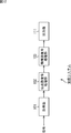
- FIG. 1 is a diagram showing an OFDM symbol.
- An OFDM symbol is generally composed of an effective symbol that is a signal interval during which IFFT is performed during transmission, and a guard interval (GI) in which a waveform in the latter half of the effective symbol is copied as it is to the beginning of the effective symbol. .
- GI guard interval
- the second generation European terrestrial digital broadcasting standard (DVB-T2) enables data transmission by MISO (Multi Input, Single Output). For example, by transmitting data using two antennas on the transmission side, diversity can be generated by combining signals transmitted from two antennas, and reception performance can be improved. become. Data transmission by MISO is particularly effective in a strong multipath environment.
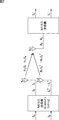
- Fig. 2 is a diagram showing data transmission by MISO in DVB-T2.
- the MISO transmitter is provided with two antennas, antenna 1 (Tx1) and antenna 2 (Tx2), and the MISO receiver is provided with one antenna (Rx1).
- the MISO transmitter receives two signals, Sa and Sb, which are Alamouti pair.
- the MISO transmitter performs Alamouti coding on Sa and Sb, and transmits Sa and Sb in that order from Tx1.
- the MISO transmitter from Tx2, (Sa) * , which is a complex conjugate of Sa, and-(Sb) * , which is a complex conjugate of Sb and whose sign is inverted, are represented by-(Sb) * , (Sa ) Send in the order of * .
- the MISO receiver estimates the transmission path characteristics H 11 , H 12 , H 21 , H 22 and performs Alamouti decoding on the received signals Ra, Rb, thereby transmitting signals Sa, Sb (Sa ′, Sb ′). To get. If the time at which Sa is transmitted from Tx1 and ⁇ (Sb) * is transmitted from Tx2 is time t1, and the time at which Sb is transmitted from Tx1 and (Sa) * is transmitted from Tx2 is time t2, H 11 represents a transmission path characteristic at time t1 between Tx1 and Rx1, and is a weight for Sa. H 12 represents transmission path characteristics at time t2 between Tx1 and Rx1, and is a weight for Sb.
- H 21 represents the transmission line characteristic at time t1 between Tx2 and Rx1, and is a weight for ⁇ (Sb) *
- H 22 represents the transmission line characteristic at time t2 between Tx2 and Rx1, and corresponds to (Sa) * . It becomes weight.
- the received signals Ra and Rb are expressed by the following expressions (1) and (2), respectively.
- Expressions (1) and (2) are expressed as determinants as shown in the following expression (3).
- Expression (3) is represented by the following Expression (4).
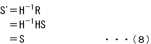
- the matrices R, H, and S are represented by the following expressions (5), (6), and (7), respectively.
- S ′ is a matrix representing a signal after decoding by Alamouti decoding.
- the MISO receiver outputs Sa ′ and Sb ′ obtained as described above.
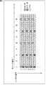
- FIG. 3 is a diagram showing an example of arrangement of SP (Scattered Pilot) when data transmission is performed by MISO.
- the horizontal axis in FIG. 3 represents the carrier number, and the vertical axis represents the symbol number.
- SP is a known signal used for estimation of transmission path characteristics.
- the European Terrestrial Digital Broadcasting Standard (DVB-T) and the Japanese Terrestrial Digital Broadcasting Standard (ISDB-T) define the SP arrangement uniquely, but DVB-T2 defines eight types of Pilot Pattern (PP). It has been.
- a PP is specified based on information included in a received signal, and transmission path characteristics are estimated using the SP.
- the SP arrangement in FIG. 3 shows the arrangement in the case of PP2.
- SP is transmitted as Sum ⁇ ⁇ ⁇ SP or Diff SP as shown in FIG.
- SUM_SP is the SP for even number symbols (symbol number is even).
- Sum SP is transmitted from Tx1 and Tx2 as SP whose polarity is not changed (hereinafter referred to as forward SP), and is added in the MISO receiver.
- Diff SP is the SP for odd-numbered symbols (with an odd symbol number). Diff SP is transmitted as normal SP from Tx1, and as SP with reversed polarity (hereinafter referred to as inverted SP) from Tx2, and is subtracted by the MISO receiver.
- the state in which the polarity is inverted is a state in which the point is symmetrical with respect to the origin on the IQ plane.
- the MISO receiver interpolates the Sum SP and Diff SP in the time direction and the frequency direction, respectively, and estimates the transmission path characteristics in all carriers.
- DVB-T2 Signaling In DVB-T2, a frame called a T2 frame is defined, and data is transmitted in units of T2 frames.
- the T2 frame includes two types of preamble signals called P1 and P2, and the preamble signal includes information necessary for processing such as demodulation of the OFDM signal.
- FIG. 4 is a diagram showing the frame structure of the T2 frame. As shown in FIG. 4, one T2 frame includes a P1 symbol, a P2 symbol, and a data symbol (Normal or FC).
- the P1 symbol is a symbol for transmitting P1 Signaling, and includes the following information a to d. a. Frame identification b. Transmission method c. FFT size d. Part of GI head
- Frame identification indicates whether the transmission frame is T2 Frame or FEF (Future Extension Frame).
- the transmission method indicates whether the transmission method is SISO (Single Input Single Output) or MISO (Multiple Input, Single Output).
- the FFT size represents the number of points for one IFFT operation on the transmission side.
- a part of the GI length indicates that the seven types of GI lengths are grouped into two, and the GI length of which group is used for symbol transmission.
- the MISO receiver only has to decode P1 Signaling. Note that the information a to d is also overlapped in the P2 symbol, but in order to decode the L1PRE Signaling and L1POST Signaling of the P2 symbol, the information a to d of the P1 Signaling is necessary.
- the first row in FIG. 5 represents a signal transmitted from Tx1 of the MISO transmitter, and the second row represents a signal transmitted from Tx2.
- the third row in FIG. 5 represents a signal received by Rx1 of the MISO receiver, and the fourth row represents an example of gain control in the MISO receiver.
- the power of DiffDSP transmitted from Tx1 as a normal SP and the reverse SP from Tx2 are transmitted.
- Diff SP power is offset in the MISO receiver.
- the power of Diff SP in the MISO receiver is “0”.
- the power of Sum SP transmitted as normal SP from Tx1 and Sum SP transmitted as normal SP from Tx2 Power is added at the MISO receiver. If the power of each Sum SP is “1”, the power of Sum SP in the MISO receiver is “2”.
- the MISO receiver has an AGC (Automatic Gain Control) function, and the power of the input OFDM signal is kept constant.
- AGC Automatic Gain Control
- the power of the input OFDM signal is kept constant.
- the power of the input OFDM signal is low, the power is increased by setting the gain high.
- the power of the input OFDM signal is high, the power is controlled by setting the gain low. Done dynamically.
- the gain increases following the detection of large power. It will be set low. Further, when the input OFDM signal is an odd-numbered symbol signal, the gain is set high following the detection of small power.
- the change in the gain surrounded by the ellipses C1 and C2 in FIG. 5 indicates that the OFDM signal is an odd-numbered symbol signal and follows that it is detected that the power is low.
- the gain tracks the power deviation of the entire OFDM signal every two symbols, and the power change of the input OFDM signal becomes large. As a result, reception performance may be degraded.
- the present technology has been made in view of such a situation, and is intended to improve reception performance even when data transmission is performed by MISO, for example.
- a receiving apparatus includes a first pilot signal transmitted as a signal having a high correlation in the direction of polarity via a different transmission path and a signal having a low correlation in the direction of the polarity via the different transmission path.
- a gain control unit that adjusts the power of a signal including the second pilot signal transmitted in this manner, and a control unit that controls a gain tracking characteristic of the gain control unit according to a data transmission method.
- a signal having a high correlation in the polarity direction includes not only a signal in which the polarity directions are completely matched, but also a signal whose value indicating the correlation in the polarity direction is equal to or greater than a threshold value.
- the signal having a low correlation in the polarity direction includes not only a signal in which the polarity direction is completely inverted, but also a signal having a value representing the correlation in the polarity direction that is less than a threshold value.
- the tracking characteristic includes the tracking speed.
- control unit can follow the gain with a characteristic different from that of SISO.
- the control unit can control the gain tracking characteristic of the gain control unit by changing a parameter defining the gain tracking characteristic.
- the time constant is included in the parameters that define the gain tracking characteristics.
- the gain tracking characteristic may be controlled by changing parameters other than the time constant.
- the control unit is configured to stop gain control while the pilot signal of any one of the first pilot signal and the second pilot signal is input, thereby tracking the gain by the gain control unit.
- the characteristics can be controlled.
- the gain control unit may adjust the power of the DVB-T2 OFDM signal so that the first pilot signal is Sum SP and the second pilot signal is Diff SP.
- a detector for detecting the P1 symbol can be further provided.
- the control unit can control the gain tracking characteristic of the gain control unit.
- the control unit can control the gain tracking characteristic of the gain control unit by setting a parameter that makes gain tracking slower than when the data transmission method is SISO.
- control unit can control the gain follow-up characteristic by the gain control unit by stopping the gain control while the pilot signal with the smaller power is input.
- a processing unit for calculating a difference between the power of the first pilot signal and the power of the second pilot signal can be further provided.
- the control unit is configured such that the transmission method of the data represented by the information included in the P1 symbol is MISO, and the power of the first pilot signal and the power of the second pilot signal are When the difference is greater than or equal to the threshold value, the gain tracking characteristic by the gain controller can be controlled.
- the control unit can control the gain tracking characteristic of the gain control unit by setting a parameter that makes gain tracking slower than when the data transmission method is SISO.
- the processing unit further specifies a pilot signal having a smaller power of the first pilot signal and the second pilot signal, and the control unit receives the pilot signal having a smaller power.
- the first pilot signal transmitted as a signal having a high correlation in the direction of polarity via a different transmission path and the signal transmitted through the different transmission path as a signal having a low correlation in the direction of polarity.
- the power of the signal including the second pilot signal thus adjusted is adjusted by the gain control unit, and the gain tracking characteristic of the gain control unit is controlled according to the data transmission method.
- reception performance can be improved.
- FIG. 6 is a block diagram illustrating a configuration example of the signal processing unit 11 provided in the reception device according to an embodiment of the present technology.
- the receiving apparatus is provided with an antenna (Rx1).
- the signal processing unit 11 includes a digital AGC unit 21, an FFT calculation unit 22, an Alamouti decoder 23, a P1 detection / signaling interpretation unit 24, a channel characteristic estimation unit 25, a digital AGC control unit 26, an equalization unit 27, and a signal switching unit. 28.
- the DVB-T2 OFDM signal obtained by subjecting the received signal received at Rx1 to A / D conversion and orthogonal demodulation to the signal processing unit 11 is input.
- the OFDM signal input to the signal processing unit 11 is a baseband signal in the time domain before the FFT operation is performed, and includes a real axis component (I component) and an imaginary axis component (Q component).
- the OFDM signal input to the signal processing unit 11 is a signal transmitted from the transmitter by SISO or MISO.
- Sum SP is transmitted as normal SP from both Tx1 and Tx2
- Diff SP is transmitted as normal SP from Tx1, and inverted SP from Tx2.
- the Sum SP is a signal transmitted through a different transmission path as a signal having a high correlation in the polarity direction
- Diff SP is a signal transmitted through a different transmission path as a signal having a low correlation in the direction of polarity. .
- the digital AGC unit 21 controls the gain (gain) and adjusts the power of the input OFDM signal.
- the gain control by the digital AGC unit 21 is performed according to a predetermined time constant set in advance.
- the time constant is one of parameters that define the tracking characteristics of gain control.
- the gain control by the digital AGC unit 21 is appropriately controlled by the digital AGC control unit 26 according to the data transmission method and the like.
- the digital AGC unit 21 outputs the power-adjusted time-domain OFDM to the FFT operation unit 22 and the P1 detection / signaling interpretation unit 24.
- the FFT operation unit 22 performs an FFT operation on the time-domain OFDM signal supplied from the digital AGC unit 21.
- the FFT calculation unit 22 outputs the OFDM signal in the frequency domain obtained by the FFT calculation to the Alamouti decoder 23, the transmission path characteristic estimation unit 25, and the equalization unit 27.
- the Alamouti decoder 23 performs Alamouti decoding using the transmission line characteristics between Tx1-Rx1 and Tx2-Rx1 in each carrier estimated by the transmission line characteristic estimation unit 25, and equalizes the OFDM signal in the frequency domain.
- the Alamouti decoder 23 outputs the equalized OFDM signal (Sa ′, Sb ′) to the signal switching unit 28.
- the P1 detection / Signaling interpretation unit 24 detects the P1 symbol included at the head of the T2 frame, and decodes the P1 Signaling transmitted by the P1 symbol. Further, the P1 detection / signaling interpretation unit 24 specifies whether the data transmission method is SISO or MISO based on P1 Signaling obtained by decoding. As described above, P1 Signaling includes information indicating whether the transmission method is SISO or MISO.
- the P1 detection / Signaling interpretation unit 24 When the P1 detection / Signaling interpretation unit 24 specifies that the data transmission method is MISO, the P1 detection / Signaling interpretation unit 24 outputs a MISO flag indicating that to the digital AGC control unit 26 and the signal switching unit 28. Information on the FFT size and part of the GI length included in P1 Signaling decoded by the P1 detection / signaling interpretation unit 24 is used in other processing units such as the FFT calculation unit 22 as appropriate.
- the transmission path characteristic estimation unit 25 extracts SP (Sum SP, Diff SP) from the OFDM signal in the frequency domain supplied from the FFT calculation unit 22, and estimates the transmission path characteristic of the carrier at the SP arrangement position.
- the transmission path characteristic estimation unit 25 interpolates the transmission path characteristics at the SP arrangement position in the time direction and the frequency direction, estimates the transmission path characteristics in each carrier of the OFDM signal, and transmits transmission path information representing the estimated transmission path characteristics.
- the data is output to the Alamouti decoder 23 and the equalization unit 27.
- the Alamouti decoder 23 is supplied with transmission path characteristics between Tx1 and Rx1 and between Tx2 and Rx1 of each carrier.
- the transmission path characteristic estimation unit 25 calculates the difference between the Sum SP power and the Diff SP power, and whether there is a power bias as described with reference to FIG. Determine whether or not. For example, if the transmission path characteristic estimation unit 25 determines that the power difference between Sum SP and Diff ⁇ ⁇ SP is greater than or equal to a threshold value, the transmission path characteristic estimation unit 25 determines that there is a bias in the power, and sets a power bias detection flag indicating the power bias detection unit 26.
- the transmission path characteristic estimation unit 25 counts the SP symbol number and outputs the symbol number information to the digital AGC control unit 26. Also, the transmission path characteristic estimation unit 25 calculates the sum of Sum SP power and the sum of Diff SP power, and determines which one of Sum SP and Diff SP has the smaller sum of power. Identify. The transmission path characteristic estimation unit 25 outputs to the digital AGC control unit 26 information indicating which of Sum SP and Diff SP has the smaller sum of power. The total sum of power is calculated using, for example, a predetermined same number of Sum ⁇ SP and Diff SP.
- the digital AGC control unit 26 controls the gain tracking characteristic of the digital AGC unit 21 when the MISO flag is supplied from the P1 detection / signaling interpretation unit 24.
- the digital AGC control unit 26 follows the gain of the digital AGC unit 21 when the MISO flag is supplied from the P1 detection / signaling interpretation unit 24 and the power deviation detection flag is supplied from the transmission path characteristic estimation unit 25. Control properties. *
- the digital AGC control unit 26 sets a time constant such that gain follow-up is slower than a predetermined time constant in the digital AGC unit 21 as a time constant for MISO, so that the gain follow-up characteristic of the digital AGC unit 21 is set.
- the MISO time constant is supplied from the digital AGC control unit 26, the digital AGC unit 21 controls the gain according to the MISO time constant instead of the predetermined time constant.
- the gain can be controlled so as not to follow it, and the fluctuation of the power of the signal output from the digital AGC unit 21 can be reduced. It becomes possible to suppress.
- the digital AGC control unit 26 outputs an AGC stop flag at the timing when the SP with the smaller sum of the powers among the Sum SP and Diff SP is input to the digital AGC unit 21, and stops gain control.
- the gain tracking characteristic of the digital AGC unit 21 is controlled.
- the timing at which the SP with the smaller total power is input to the digital AGC unit 21 is specified based on the symbol number supplied from the transmission path characteristic estimation unit 25.
- the digital AGC unit 21 stops gain control while the SP with the smaller total power is input. While the gain control is stopped, the power adjustment itself may be stopped, or the power adjustment may be continued using the gain immediately before the gain control is stopped.
- the equalization unit 27 equalizes the frequency domain OFDM signal using the channel characteristics of each carrier estimated by the channel characteristic estimation unit 25, and outputs the equalized OFDM signal to the signal switching unit 28. .
- the signal switching unit 28 When the MISO flag is supplied from the P1 detection / signaling interpretation unit 24, that is, when the data transmission method is MISO, the signal switching unit 28 outputs the signal supplied from the Alamouti decoder 23 to an error correction unit (not shown). To do. Further, when the MISO flag is not supplied from the P1 detection / signaling interpretation unit 24, that is, when the data transmission method is SISO, the signal switching unit 28 does not show the signal supplied from the equalization unit 27 as an error correction unit (not shown). Output to.
- step S1 the digital AGC unit 21 controls the gain according to a predetermined time constant and adjusts the power of the input OFDM signal.
- step S2 the P1 detection / signaling interpretation unit 24 detects a P1 symbol.
- step S3 the P1 detection / signaling interpretation unit 24 decodes P1 Signaling transmitted by the P1 symbol.
- step S4 the P1 detection / signaling interpretation unit 24 determines whether or not the data transmission method is MISO based on information included in P1 Signaling.
- step S4 If it is determined in step S4 that the data transmission method is MISO, the P1 detection / signaling interpretation unit 24 outputs the MISO flag to the digital AGC control unit 26 in step S5.
- step S6 the digital AGC control unit 26 performs a tracking characteristic control process.
- the tracking characteristic control process will be described later with reference to the flowcharts of FIGS.
- step S7 the digital AGC unit 21 controls the gain according to the control by the digital AGC control unit 26, and outputs the time-domain OFDM signal whose power is adjusted to the FFT calculation unit 22.
- step S8 the FFT operation unit 22 performs an FFT operation on the time-domain OFDM signal supplied from the digital AGC unit 21.
- step S9 the transmission path characteristic estimation unit 25, based on the SP included in the frequency domain OFDM signal supplied from the FFT computation unit 22, between Tx1-Rx1 and Tx2-Rx1 in each carrier of the OFDM signal. Estimate transmission path characteristics.
- step S10 the Alamouti decoder 23 performs Alamouti decoding using the transmission path characteristic estimated by the transmission path characteristic estimation unit 25, and equalizes the frequency domain OFDM signal.
- the Alamouti decoder 23 outputs the equalized OFDM signal.
- the equalized OFDM signal output from the Alamouti decoder 23 is selected by the signal switching unit 28 and output to the error correction unit. Thereafter, the process ends.
- each unit of the signal processing unit 11 performs a normal demodulation operation in step S11. That is, the digital AGC unit 21 controls the gain according to a predetermined time constant, and the FFT operation unit 22 performs an FFT operation on the time-domain OFDM signal whose power is adjusted.
- the channel characteristic estimation unit 25 estimates the channel characteristic based on the SP included in the frequency domain OFDM signal, and the equalization unit 27 uses the estimated channel characteristic to calculate the frequency domain OFDM signal, etc. To do.
- the equalized OFDM signal output from the equalization unit 27 is selected by the signal switching unit 28 and output to the error correction unit.
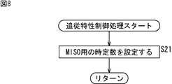
- the process of FIG. 8 is a process of controlling the gain tracking characteristic by setting a time constant for MISO.
- step S21 the digital AGC control unit 26 sets a time constant for MISO in the digital AGC unit 21 in which gain follow-up is slower than a predetermined time constant. Thereafter, the processing after step S6 in FIG. 7 is performed.
- step S7 the digital AGC unit 21 controls the gain according to the time constant for MISO.
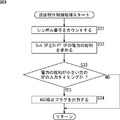
- the process of FIG. 9 is a process of controlling the gain tracking characteristic by stopping the gain control.
- step S31 the transmission path characteristic estimation unit 25 counts the SP symbol number and outputs the symbol number information to the digital AGC control unit 26.
- step S32 the transmission path characteristic estimation unit 25 calculates the sum of Sum SP power and the sum of Diff SP power, and either SP of Sum SP or Diff SP has a smaller sum of power. To identify.
- the transmission path characteristic estimation unit 25 outputs information representing the SP having the smaller total power to the digital AGC control unit 26.
- step S ⁇ b> 33 the digital AGC control unit 26 determines whether or not the current timing is a timing at which the SP having the smaller total power is input to the digital AGC unit 21.
- step S33 If it is determined in step S33 that the SP with the smaller total power is input to the digital AGC unit 21, the digital AGC control unit 26 outputs an AGC stop flag to the digital AGC unit 21 in step S34. The process is terminated. Thereafter, the processing from step S6 onward in FIG. 7 is performed. In step S7, in response to the supply of the AGC stop flag, the digital AGC unit 21 inputs the SP with the smaller total power, Gain control is stopped.
- step S34 is skipped, and the digital AGC control unit 26 ends the process. Thereafter, the processing after step S6 in FIG. 7 is performed.
- step S7 the digital AGC unit 21 controls the gain according to a predetermined time constant.
- step S41 the digital AGC unit 21 adjusts the power of the input OFDM signal by controlling the gain according to a predetermined time constant.
- step S42 the P1 detection / signaling interpretation unit 24 detects a P1 symbol.
- step S43 the P1 detection / signaling interpretation unit 24 decodes P1 Signaling transmitted by the P1 symbol.
- step S44 the P1 detection / signaling interpretation unit 24 determines whether or not the data transmission method is MISO based on information included in P1 Signaling.
- step S44 If it is determined in step S44 that the data transmission method is MISO, the P1 detection / signaling interpretation unit 24 outputs the MISO flag to the digital AGC control unit 26 in step S45.
- step S46 the FFT operation unit 22 performs an FFT operation on the time-domain OFDM signal supplied from the digital AGC unit 21.
- step S47 the transmission path characteristic estimation unit 25, based on the SP included in the OFDM signal in the frequency domain supplied from the FFT calculation unit 22, between Tx1-Rx1 and between Tx2-Rx1 in each carrier of the OFDM signal. Estimate transmission path characteristics.
- step S48 the transmission path characteristic estimator 25 calculates the difference between the Sum SP power and the Diff SP power.
- step S49 the transmission path characteristic estimation unit 25 determines whether there is a power bias as described with reference to FIG. 5 based on the difference between the Sum ⁇ SP power and the Diff SP power.
- step S49 If it is determined in step S49 that there is a power bias, the transmission path characteristic estimation unit 25 outputs a power bias detection flag to the digital AGC control unit 26 in step S50.
- step S51 the digital AGC control unit 26 performs a tracking characteristic control process.
- the tracking characteristic control process the process described with reference to the flowchart of FIG. 8 or the process described with reference to the flowchart of FIG. 9 is performed.
- step S52 the digital AGC unit 21 performs gain control according to the control by the digital AGC control unit 26, and outputs an OFDM signal in a time domain in which power is adjusted to the FFT calculation unit 22.
- step S53 the FFT computation unit 22 performs FFT computation on the time-domain OFDM signal in which the tracking characteristic of the gain is controlled by the processing of FIG. 8 or 9, and the power is adjusted according to the gain for which the tracking characteristic is controlled. Apply.
- step S54 the Alamouti decoder 23 performs Alamouti decoding using the transmission path characteristic estimated by the transmission path characteristic estimation unit 25, and equalizes the frequency domain OFDM signal.
- the Alamouti decoder 23 outputs the equalized OFDM signal.
- the equalized OFDM signal output from the Alamouti decoder 23 is selected by the signal switching unit 28 and output to the error correction unit. Thereafter, the process ends.
- step S44 determines whether the data transmission method is SISO instead of MISO, or if it is determined in step S49 that there is no bias in power
- each unit of the signal processing unit 11 is normally set in step S55.
- the demodulation operation is performed. That is, if it is determined in step S44 that the data transmission method is not MISO but SISO, the same processing as step S11 in FIG. 7 is performed. If it is determined in step S49 that there is no bias in power, data transmitted by MISO is demodulated without controlling the gain tracking characteristics.
- the gain can be controlled so that it does not follow it, and fluctuations in power of the OFDM signal can be suppressed. Become. In addition, it is possible to suppress degradation of reception performance in the signal processing unit 11.
- control the former control method when the sum of power of Sum ⁇ SP and Diff SP is less than the threshold, and control the latter when the difference of sum of power of Sum SP and Diff SP is greater than or equal to the threshold. It is possible to use a method. It is also possible to change the control method of the gain tracking characteristic according to PP.
- FIG. 11 is a block diagram illustrating a configuration example of the first embodiment of the reception system to which the signal processing unit 11 is applied.
- 11 includes an acquisition unit 101, a transmission path decoding processing unit 102, and an information source decoding processing unit 103.
- the acquisition unit 101 acquires a signal via a transmission path (not shown) such as terrestrial digital broadcast, satellite digital broadcast, CATV network, Internet, or other network, and supplies the signal to the transmission path decoding processing unit 102.
- a transmission path such as terrestrial digital broadcast, satellite digital broadcast, CATV network, Internet, or other network.
- the signal processing unit 11 in FIG. 6 is included in the acquisition unit 101, for example.
- the transmission path decoding processing unit 102 performs transmission path decoding processing including error correction on the signal acquired by the acquisition unit 101 via the transmission path, and supplies the resulting signal to the information source decoding processing unit 103. .
- the information source decoding processing unit 103 performs an information source decoding process including a process of expanding the compressed information to the original information and acquiring the transmission target data for the signal subjected to the transmission path decoding process.
- the signal acquired by the acquisition unit 101 via the transmission path may be subjected to compression coding for compressing information in order to reduce the amount of data such as images and sounds.
- the information source decoding processing unit 103 performs information source decoding processing such as processing for expanding the compressed information to the original information on the signal subjected to the transmission path decoding processing.
- the information source decoding processing unit 103 does not perform the process of expanding the compressed information to the original information.
- examples of the decompression process include MPEG decoding.
- the information source decoding process may include descrambling in addition to the decompression process.
- the receiving system of FIG. 11 can be applied to, for example, a TV tuner that receives digital television broadcasting.
- the acquisition unit 101, the transmission path decoding processing unit 102, and the information source decoding processing unit 103 are each configured as one independent device (hardware (IC (Integrated Circuit), etc.)) or software module). Is possible.
- the acquisition unit 101, the transmission path decoding processing unit 102, and the information source decoding processing unit 103 it is possible to configure those three sets as one independent device. It is also possible to configure the set of the acquisition unit 101 and the transmission path decoding processing unit 102 as one independent device, and the set of the transmission path decoding processing unit 102 and the information source decoding processing unit 103 as one independent device It can also be configured as a device.
- FIG. 12 is a block diagram illustrating a configuration example of the second embodiment of the reception system to which the signal processing unit 11 is applied.
- the configuration of the reception system in FIG. 12 is the same as the configuration in FIG. 11 in that the acquisition unit 101, the transmission path decoding processing unit 102, and the information source decoding processing unit 103 are included, and an output unit 111 is newly provided. This is different from the configuration of FIG.
- the output unit 111 is, for example, a display device that displays an image or a speaker that outputs audio, and outputs an image, audio, or the like as a signal output from the information source decoding processing unit 103. That is, the output unit 111 displays an image or outputs sound.
- a TV that receives a television broadcast as a digital broadcast
- a radio receiver that receives a radio broadcast
- the signal output from the transmission path decoding processing unit 102 is directly supplied to the output unit 111.
- FIG. 13 is a block diagram illustrating a configuration example of the third embodiment of the reception system to which the signal processing unit 11 is applied.
- the configuration of the reception system in FIG. 13 is the same as the configuration in FIG. 11 in that the acquisition unit 101 and the transmission path decoding processing unit 102 are provided, the information source decoding processing unit 103 is not provided, and the recording unit 121 is newly added. 11 is different from the configuration of FIG.
- the recording unit 121 records a signal (for example, TS packet of MPEG TS) output from the transmission path decoding processing unit 102 on a recording (storage) medium such as an optical disk, a hard disk (magnetic disk), or a flash memory (memory). )
- a recording (storage) medium such as an optical disk, a hard disk (magnetic disk), or a flash memory (memory).
- the reception system of FIG. 13 as described above can be applied to a recorder device that records a television broadcast.
- the information source decoding processing unit 103 is provided, and the signal after the information source decoding processing is performed by the information source decoding processing unit 103, that is, the image or sound obtained by decoding is recorded by the recording unit 121. Good.
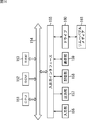
- FIG. 14 is a block diagram illustrating a configuration example of hardware of a computer that executes the above-described series of processes by a program.
- a CPU Central Processing Unit
- ROM Read Only Memory
- RAM Random Access Memory
- An input / output interface 155 is further connected to the bus 154.
- the input / output interface 155 is connected to an input unit 156 composed of a keyboard, a mouse, etc., and an output unit 157 composed of a display, a speaker, and the like.
- the input / output interface 155 is connected to a storage unit 158 made up of a hard disk, a non-volatile memory, etc., a communication unit 159 made up of a network interface, etc., and a drive 160 that drives the removable media 161.
- the CPU 151 loads the program stored in the storage unit 158 to the RAM 153 via the input / output interface 155 and the bus 154 and executes it, thereby executing the above-described series of processing. Is done.
- the program executed by the CPU 151 is recorded on the removable medium 161 or provided via a wired or wireless transmission medium such as a local area network, the Internet, or digital broadcasting, and is installed in the storage unit 158.
- the program executed by the computer may be a program that is processed in time series in the order described in this specification, or in parallel or at a necessary timing such as when a call is made. It may be a program for processing.
- Embodiments of the present technology are not limited to the above-described embodiments, and various modifications can be made without departing from the gist of the present technology.
- the present technology may have the following configurations.
- a gain control unit for adjusting the power of the signal including And a control unit that controls a tracking characteristic of gain by the gain control unit according to a data transmission method.
- control unit controls a gain tracking characteristic of the gain control unit by changing a parameter that defines a gain tracking characteristic.
- the control unit stops the gain control while the pilot signal of either the first pilot signal or the second pilot signal is input, so that the gain tracking characteristic of the gain control unit is stopped.
- the receiving device according to (1) or (2).
- the gain control unit adjusts the power of the DVB-T2 OFDM signal,
- the first pilot signal is Sum SP;
- the receiving apparatus according to any one of (1) to (4), wherein the second pilot signal is Diff SP.
- a detection unit for detecting the P1 symbol The receiving apparatus according to (5), wherein the control unit controls a tracking characteristic of gain by the gain control unit when a transmission method of data represented by information included in the P1 symbol is MISO.
- the control unit controls a gain tracking characteristic of the gain control unit by setting a parameter that makes gain tracking slower than when the data transmission method is SISO. (5) or (6) Receiver.
- the control unit controls gain follow-up characteristics by the gain control unit by stopping control of gain while the pilot signal having a smaller power is input.
- a processing unit for calculating a difference between the power of the first pilot signal and the power of the second pilot signal In the control unit, a transmission method of data represented by information included in the P1 symbol is MISO, and a difference between the power of the first pilot signal and the power of the second pilot signal is equal to or greater than a threshold value If it is, The receiving apparatus as described in said (6) which controls the tracking characteristic of the gain by the said gain control part.
- the processing unit further specifies a pilot signal having a smaller power of the first pilot signal and the second pilot signal,
- the receiving device according to (9), wherein the control unit controls gain tracking characteristics by the gain control unit by stopping control of gain while the pilot signal with smaller power is input.
- the power of the signal including
- the power of the signal including the pilot signal is adjusted by the gain control unit,
Landscapes
- Engineering & Computer Science (AREA)
- Signal Processing (AREA)
- Computer Networks & Wireless Communication (AREA)
- Power Engineering (AREA)
- Circuits Of Receivers In General (AREA)
- Radio Transmission System (AREA)
- Cable Transmission Systems, Equalization Of Radio And Reduction Of Echo (AREA)
Abstract
Description
OFDM(Orthogonal Frequency Division Multiplexing)方式によるデータ伝送は、伝送帯域内に多数の直交するサブキャリア(副搬送波)を使用し、それぞれのサブキャリアの振幅や位相にデータを割り当てることによって行われる。データはOFDMシンボルと呼ばれるシンボル単位で伝送される。OFDMシンボルに対しては、送信時にIFFT(Inverse Fast Fourier Transform)が行われる。
第2世代欧州地上波デジタル放送規格(DVB-T2)ではMISO(Multi Input, Single Output)によるデータ伝送が可能になっている。例えば送信側で2本のアンテナを利用してデータを送信することにより、2本のアンテから送信される信号の組み合わせによってダイバーシチ(diversity)を生じさせることができ、受信性能を向上させることが可能になる。MISOによるデータ伝送は、特に、強いマルチパスの環境下において有効とされている。







DVB-T2では、T2フレームと呼ばれるフレームが定義され、データはT2フレーム単位で送信される。
a.フレーム識別
b.伝送方式
c.FFTサイズ
d.GI長の一部
Tx1-Rx1間、Tx2-Rx1間の伝送路の振幅特性および位相特性が同一である場合(H11=H21,H12=H22である場合)
この場合、図5に示すように、奇数番号のシンボルでは、Tx1からの正転SPと、Tx2からの反転SPが相殺され、MISO受信機におけるDiff SPの電力は"0"になる。つまり、2シンボル毎にSPの電力が"0"になる。
Tx1-Rx1間、Tx2-Rx1間の伝送路の振幅特性が同一であり、位相特性が逆位相である場合(H11=-H21,H12=-H22である場合)
この場合、例1の場合と反対に、偶数番号のシンボルでは、Tx1からの正転SPと、Tx2からの正転SPが相殺され、Sum SPの電力は"0"になる。つまり、2シンボル毎にSPの電力が"0"になる。
図6は、本技術の一実施形態に係る受信装置に設けられる信号処理部11の構成例を示すブロック図である。
ここで、受信装置の動作について説明する。各ステップの処理は、適宜、他のステップの処理と並行して、または、他のステップの処理と前後して行われる。
MISO用の時定数を用いる制御方法と、電力の総和が小さい方のSPが入力されるタイミングでゲイン制御を停止させる制御方法の2つのうちのいずれかの方法によってゲインの追従特性を制御するものとしたが、2つの制御方法を適宜切り替えるようにしてもよい。
図11は、信号処理部11を適用した受信システムの第1実施の形態の構成例を示すブロック図である。
上述した一連の処理は、ハードウェアにより実行することもできるし、ソフトウェアにより実行することもできる。一連の処理をソフトウェアにより実行する場合には、そのソフトウェアを構成するプログラムが、専用のハードウェアに組み込まれているコンピュータ、または汎用のパーソナルコンピュータなどに、プログラム記録媒体からインストールされる。
極性の方向の相関が高い信号として異なる伝送路を介して送信された第1のパイロット信号と、極性の方向の相関が低い信号として前記異なる伝送路を介して送信された第2のパイロット信号とを含む信号の電力を調整する利得制御部と、
データの伝送方式に応じて、前記利得制御部による利得の追従特性を制御する制御部と を備える受信装置。
前記制御部は、データの伝送方式がMISOである場合、SISOである場合と異なる特性で利得を追従させる
前記(1)に記載の受信装置。
前記制御部は、利得の追従特性を規定するパラメータを変えることによって、前記利得制御部による利得の追従特性を制御する
前記(1)または(2)に記載の受信装置。
前記制御部は、前記第1のパイロット信号と前記第2のパイロット信号のうちのいずれかのパイロット信号が入力される間の利得の制御を停止させることによって、前記利得制御部による利得の追従特性を制御する
前記(1)または(2)に記載の受信装置。
前記利得制御部は、DVB-T2のOFDM信号の電力を調整し、
前記第1のパイロット信号は、Sum SPであり、
前記第2のパイロット信号は、Diff SPである
前記(1)乃至(4)のいずれかに記載の受信装置。
P1シンボルを検出する検出部をさらに備え、
前記制御部は、前記P1シンボルに含まれる情報により表されるデータの伝送方式がMISOである場合、前記利得制御部による利得の追従特性を制御する
前記(5)に記載の受信装置。
前記制御部は、データの伝送方式がSISOである場合より利得の追従が遅くなるパラメータを設定することによって、前記利得制御部による利得の追従特性を制御する
前記(5)または(6)に記載の受信装置。
前記OFDM信号から前記第1のパイロット信号と前記第2のパイロット信号を抽出し、電力の小さい方のパイロット信号を特定する処理部をさらに備え、
前記制御部は、電力の小さい方の前記パイロット信号が入力される間の利得の制御を停止させることによって、前記利得制御部による利得の追従特性を制御する
前記(5)または(6)に記載の受信装置。
前記第1のパイロット信号の電力と前記第2のパイロット信号の電力との差を計算する処理部をさらに備え、
前記制御部は、前記P1シンボルに含まれる情報により表されるデータの伝送方式がMISOであり、かつ、前記第1のパイロット信号の電力と前記第2のパイロット信号の電力との差が閾値以上である場合、前記利得制御部による利得の追従特性を制御する
前記(6)に記載の受信装置。
前記制御部は、データの伝送方式がSISOである場合より利得の追従が遅くなるパラメータを設定することによって、前記利得制御部による利得の追従特性を制御する
前記(9)に記載の受信装置。
前記処理部は、さらに、前記第1のパイロット信号と前記第2のパイロット信号のうちの電力の小さい方のパイロット信号を特定し、
前記制御部は、電力の小さい方の前記パイロット信号が入力される間の利得の制御を停止させることによって、前記利得制御部による利得の追従特性を制御する
前記(9)に記載の受信装置。
極性の方向の相関が高い信号として異なる伝送路を介して送信された第1のパイロット信号と、極性の方向の相関が低い信号として前記異なる伝送路を介して送信された第2のパイロット信号とを含む信号の電力を利得制御部によって調整し、
データの伝送方式に応じて、前記利得制御部による利得の追従特性を制御する
ステップを含む受信方法。
データの伝送方式に応じて、前記利得制御部による利得の追従特性を制御する
ステップを含む処理をコンピュータに実行させるプログラム。
Claims (13)
- 極性の方向の相関が高い信号として異なる伝送路を介して送信された第1のパイロット信号と、極性の方向の相関が低い信号として前記異なる伝送路を介して送信された第2のパイロット信号とを含む信号の電力を調整する利得制御部と、
データの伝送方式に応じて、前記利得制御部による利得の追従特性を制御する制御部と
を備える受信装置。 - 前記制御部は、データの伝送方式がMISOである場合、SISOである場合と異なる特性で利得を追従させる
請求項1に記載の受信装置。 - 前記制御部は、利得の追従特性を規定するパラメータを変えることによって、前記利得制御部による利得の追従特性を制御する
請求項1に記載の受信装置。 - 前記制御部は、前記第1のパイロット信号と前記第2のパイロット信号のうちのいずれかのパイロット信号が入力される間の利得の制御を停止させることによって、前記利得制御部による利得の追従特性を制御する
請求項1に記載の受信装置。 - 前記利得制御部は、DVB-T2のOFDM信号の電力を調整し、
前記第1のパイロット信号は、Sum SPであり、
前記第2のパイロット信号は、Diff SPである
請求項1に記載の受信装置。 - P1シンボルを検出する検出部をさらに備え、
前記制御部は、前記P1シンボルに含まれる情報により表されるデータの伝送方式がMISOである場合、前記利得制御部による利得の追従特性を制御する
請求項5に記載の受信装置。 - 前記制御部は、データの伝送方式がSISOである場合より利得の追従が遅くなるパラメータを設定することによって、前記利得制御部による利得の追従特性を制御する
請求項6に記載の受信装置。 - 前記OFDM信号から前記第1のパイロット信号と前記第2のパイロット信号を抽出し、電力の小さい方のパイロット信号を特定する処理部をさらに備え、
前記制御部は、電力の小さい方の前記パイロット信号が入力される間の利得の制御を停止させることによって、前記利得制御部による利得の追従特性を制御する
請求項6に記載の受信装置。 - 前記第1のパイロット信号の電力と前記第2のパイロット信号の電力との差を計算する処理部をさらに備え、
前記制御部は、前記P1シンボルに含まれる情報により表されるデータの伝送方式がMISOであり、かつ、前記第1のパイロット信号の電力と前記第2のパイロット信号の電力との差が閾値以上である場合、前記利得制御部による利得の追従特性を制御する
請求項6に記載の受信装置。 - 前記制御部は、データの伝送方式がSISOである場合より利得の追従が遅くなるパラメータを設定することによって、前記利得制御部による利得の追従特性を制御する
請求項9に記載の受信装置。 - 前記処理部は、さらに、前記第1のパイロット信号と前記第2のパイロット信号のうちの電力の小さい方のパイロット信号を特定し、
前記制御部は、電力の小さい方の前記パイロット信号が入力される間の利得の制御を停止させることによって、前記利得制御部による利得の追従特性を制御する
請求項9に記載の受信装置。 - 極性の方向の相関が高い信号として異なる伝送路を介して送信された第1のパイロット信号と、極性の方向の相関が低い信号として前記異なる伝送路を介して送信された第2のパイロット信号とを含む信号の電力を利得制御部によって調整し、
データの伝送方式に応じて、前記利得制御部による利得の追従特性を制御する
ステップを含む受信方法。 - 極性の方向の相関が高い信号として異なる伝送路を介して送信された第1のパイロット信号と、極性の方向の相関が低い信号として前記異なる伝送路を介して送信された第2のパイロット信号とを含む信号の電力を利得制御部によって調整し、
データの伝送方式に応じて、前記利得制御部による利得の追従特性を制御する
ステップを含む処理をコンピュータに実行させるプログラム。
Priority Applications (5)
| Application Number | Priority Date | Filing Date | Title |
|---|---|---|---|
| EP12754426.0A EP2685647A4 (en) | 2011-03-10 | 2012-03-01 | RECEIVING DEVICE, RECEIVING METHOD AND PROGRAM |
| BR112013022539A BR112013022539A2 (pt) | 2011-03-10 | 2012-03-01 | dispositivo receptor, método de recepção, e, programa |
| CN201280011460.3A CN103404056B (zh) | 2011-03-10 | 2012-03-01 | 接收设备、接收方法和程序 |
| RU2013140774/07A RU2597002C2 (ru) | 2011-03-10 | 2012-03-01 | Устройство приема, способ приема и программа |
| US14/000,064 US9203674B2 (en) | 2011-03-10 | 2012-03-01 | Receiving device, receiving method, and program |
Applications Claiming Priority (2)
| Application Number | Priority Date | Filing Date | Title |
|---|---|---|---|
| JP2011053064A JP5668979B2 (ja) | 2011-03-10 | 2011-03-10 | 受信装置、受信方法、およびプログラム |
| JP2011-053064 | 2011-03-10 |
Publications (1)
| Publication Number | Publication Date |
|---|---|
| WO2012121104A1 true WO2012121104A1 (ja) | 2012-09-13 |
Family
ID=46798071
Family Applications (1)
| Application Number | Title | Priority Date | Filing Date |
|---|---|---|---|
| PCT/JP2012/055234 Ceased WO2012121104A1 (ja) | 2011-03-10 | 2012-03-01 | 受信装置、受信方法、およびプログラム |
Country Status (7)
| Country | Link |
|---|---|
| US (1) | US9203674B2 (ja) |
| EP (1) | EP2685647A4 (ja) |
| JP (1) | JP5668979B2 (ja) |
| CN (1) | CN103404056B (ja) |
| BR (1) | BR112013022539A2 (ja) |
| RU (1) | RU2597002C2 (ja) |
| WO (1) | WO2012121104A1 (ja) |
Families Citing this family (13)
| Publication number | Priority date | Publication date | Assignee | Title |
|---|---|---|---|---|
| US7327803B2 (en) | 2004-10-22 | 2008-02-05 | Parkervision, Inc. | Systems and methods for vector power amplification |
| US7911272B2 (en) | 2007-06-19 | 2011-03-22 | Parkervision, Inc. | Systems and methods of RF power transmission, modulation, and amplification, including blended control embodiments |
| EP2715867A4 (en) * | 2011-06-02 | 2014-12-17 | Parkervision Inc | ANTENNA CONTROL |
| US9479233B2 (en) | 2012-11-08 | 2016-10-25 | Intel Corporation | Apparatus, system and method of multi-input-multi-output (MIMO) beamformed communication with space block coding |
| WO2015042142A1 (en) | 2013-09-17 | 2015-03-26 | Parkervision, Inc. | Method, apparatus and system for rendering an information bearing function of time |
| CA3016736C (en) * | 2014-08-07 | 2019-12-17 | ONE Media, LLC | Dynamic configuration of a flexible orthogonal frequency division multiplexing phy transport data frame |
| KR20170051437A (ko) | 2014-08-07 | 2017-05-11 | 코히어런트 로직스, 인코포레이티드 | 멀티-파티션 라디오 프레임 |
| CN105024878B (zh) * | 2015-06-30 | 2018-07-20 | 芯海科技(深圳)股份有限公司 | 一种ofdm集群系统的时延测量方法 |
| MX2021004799A (es) * | 2015-07-23 | 2022-12-07 | Samsung Electronics Co Ltd | Aparato de transmision, aparato de recepcion, y metodos de control de los mismos. |
| JP6953693B2 (ja) * | 2016-09-15 | 2021-10-27 | ソニーグループ株式会社 | 送信装置、及び、送信方法 |
| CN109861808B (zh) * | 2017-11-30 | 2021-10-22 | 上海数字电视国家工程研究中心有限公司 | 前径搜索方法及装置 |
| CN110166198B (zh) * | 2018-02-12 | 2024-07-02 | 北京三星通信技术研究有限公司 | 旁路信号发送方法和设备 |
| US10658118B2 (en) * | 2018-02-13 | 2020-05-19 | Samsung Electro-Mechanics Co., Ltd. | Electronic component and board having the same |
Citations (2)
| Publication number | Priority date | Publication date | Assignee | Title |
|---|---|---|---|---|
| JP2001177426A (ja) * | 1999-12-21 | 2001-06-29 | Hitachi Kokusai Electric Inc | 通信装置 |
| EP2259516A2 (en) * | 2009-06-03 | 2010-12-08 | Sony Corporation | Method and apparatus for channel estimation using pilot signals |
Family Cites Families (13)
| Publication number | Priority date | Publication date | Assignee | Title |
|---|---|---|---|---|
| KR100252971B1 (ko) * | 1998-02-25 | 2000-04-15 | 구자홍 | 디지털 방송 수신기의 자동주파수 제어방법 |
| RU2192709C2 (ru) * | 2000-11-30 | 2002-11-10 | Гармонов Александр Васильевич | Способ приема многолучевых сигналов в системе радиосвязи с кодовым разделением каналов и устройство для его реализации |
| US8320301B2 (en) * | 2002-10-25 | 2012-11-27 | Qualcomm Incorporated | MIMO WLAN system |
| US7508798B2 (en) * | 2002-12-16 | 2009-03-24 | Nortel Networks Limited | Virtual mimo communication system |
| BRPI0418710B8 (pt) * | 2004-03-30 | 2018-03-20 | Mitsubishi Electric Corp | método e sistema de comunicação relativos a um serviço de difusão múltipla de transmissão de multimídia (mbms), estação móvel, método de comunicação para utilização em uma estação de base, e, estação de base. |
| US7966033B2 (en) * | 2006-01-05 | 2011-06-21 | Qualcomm Incorporated | Serving sector directed power control |
| EP2071758A1 (en) * | 2007-12-11 | 2009-06-17 | Sony Corporation | OFDM-Transmitting apparatus and method, and OFDM-receiving apparatus and method |
| US8229036B2 (en) * | 2007-12-21 | 2012-07-24 | Broadcom Corporation | Characterizing channel response using data tone decision feedback |
| US8189689B2 (en) * | 2008-08-12 | 2012-05-29 | Himax Technologies Limited | Receiver for reducing PCR jitter |
| JP4661938B2 (ja) * | 2008-10-28 | 2011-03-30 | ソニー株式会社 | 無線通信装置及び無線通信方法、並びにコンピューター・プログラム |
| GB2470768A (en) * | 2009-06-03 | 2010-12-08 | Sony Corp | Receiver for OFDM symbols in a MISO system with Alamouti-type encoding |
| US8743977B2 (en) * | 2009-06-23 | 2014-06-03 | Intel Corporation | Efficient tuning and demodulation techniques |
| JP5392554B2 (ja) * | 2009-07-24 | 2014-01-22 | ソニー株式会社 | 受信装置及び方法、プログラム、並びに受信システム |
-
2011
- 2011-03-10 JP JP2011053064A patent/JP5668979B2/ja not_active Expired - Fee Related
-
2012
- 2012-03-01 CN CN201280011460.3A patent/CN103404056B/zh not_active Expired - Fee Related
- 2012-03-01 EP EP12754426.0A patent/EP2685647A4/en not_active Withdrawn
- 2012-03-01 BR BR112013022539A patent/BR112013022539A2/pt not_active Application Discontinuation
- 2012-03-01 WO PCT/JP2012/055234 patent/WO2012121104A1/ja not_active Ceased
- 2012-03-01 RU RU2013140774/07A patent/RU2597002C2/ru active
- 2012-03-01 US US14/000,064 patent/US9203674B2/en not_active Expired - Fee Related
Patent Citations (2)
| Publication number | Priority date | Publication date | Assignee | Title |
|---|---|---|---|---|
| JP2001177426A (ja) * | 1999-12-21 | 2001-06-29 | Hitachi Kokusai Electric Inc | 通信装置 |
| EP2259516A2 (en) * | 2009-06-03 | 2010-12-08 | Sony Corporation | Method and apparatus for channel estimation using pilot signals |
Non-Patent Citations (2)
| Title |
|---|
| "Frame structure channel coding and modulation for a second generation digital terrestrial television broadcasting system (DVB-T2", DVB DOCUMENT A122, June 2008 (2008-06-01) |
| See also references of EP2685647A4 |
Also Published As
| Publication number | Publication date |
|---|---|
| JP2012191431A (ja) | 2012-10-04 |
| US9203674B2 (en) | 2015-12-01 |
| CN103404056B (zh) | 2017-04-12 |
| JP5668979B2 (ja) | 2015-02-12 |
| RU2013140774A (ru) | 2015-03-10 |
| BR112013022539A2 (pt) | 2016-11-29 |
| EP2685647A4 (en) | 2014-08-27 |
| CN103404056A (zh) | 2013-11-20 |
| RU2597002C2 (ru) | 2016-09-10 |
| EP2685647A1 (en) | 2014-01-15 |
| US20130329839A1 (en) | 2013-12-12 |
Similar Documents
| Publication | Publication Date | Title |
|---|---|---|
| JP5668979B2 (ja) | 受信装置、受信方法、およびプログラム | |
| US8488695B2 (en) | Receiving apparatus and method, program, and receiving system | |
| JP2012191565A (ja) | 受信装置、受信方法、およびプログラム | |
| JP5392554B2 (ja) | 受信装置及び方法、プログラム、並びに受信システム | |
| JP5278173B2 (ja) | 受信装置および方法、プログラム、並びに受信システム | |
| US9210017B2 (en) | Reception device, reception method, and program | |
| US7929622B2 (en) | Method of channel estimation | |
| JP7054326B2 (ja) | Ofdm送受信装置 | |
| JP5712698B2 (ja) | 信号処理装置、信号処理方法、並びにプログラム | |
| JP2007158424A (ja) | ダイバーシチ受信方法およびそれを利用した受信装置 | |
| JP4557835B2 (ja) | ダイバーシチ受信装置 | |
| WO2015174294A1 (ja) | 信号処理装置および信号処理方法、並びにプログラム | |
| JP5543033B2 (ja) | 受信装置および受信方法 | |
| JP2008177937A (ja) | ダイバーシチ受信装置 | |
| WO2017006471A1 (ja) | 受信装置及び受信方法 |
Legal Events
| Date | Code | Title | Description |
|---|---|---|---|
| 121 | Ep: the epo has been informed by wipo that ep was designated in this application |
Ref document number: 12754426 Country of ref document: EP Kind code of ref document: A1 |
|
| WWE | Wipo information: entry into national phase |
Ref document number: 14000064 Country of ref document: US |
|
| ENP | Entry into the national phase |
Ref document number: 2013140774 Country of ref document: RU Kind code of ref document: A |
|
| NENP | Non-entry into the national phase |
Ref country code: DE |
|
| REG | Reference to national code |
Ref country code: BR Ref legal event code: B01A Ref document number: 112013022539 Country of ref document: BR |
|
| ENP | Entry into the national phase |
Ref document number: 112013022539 Country of ref document: BR Kind code of ref document: A2 Effective date: 20130903 |