WO2012121247A1 - スパー型浮体構造物 - Google Patents
スパー型浮体構造物 Download PDFInfo
- Publication number
- WO2012121247A1 WO2012121247A1 PCT/JP2012/055676 JP2012055676W WO2012121247A1 WO 2012121247 A1 WO2012121247 A1 WO 2012121247A1 JP 2012055676 W JP2012055676 W JP 2012055676W WO 2012121247 A1 WO2012121247 A1 WO 2012121247A1
- Authority
- WO
- WIPO (PCT)
- Prior art keywords
- floating body
- extension
- spar type
- type floating
- structure according
- Prior art date
- Legal status (The legal status is an assumption and is not a legal conclusion. Google has not performed a legal analysis and makes no representation as to the accuracy of the status listed.)
- Ceased
Links
Images


Classifications
-
- B—PERFORMING OPERATIONS; TRANSPORTING
- B63—SHIPS OR OTHER WATERBORNE VESSELS; RELATED EQUIPMENT
- B63B—SHIPS OR OTHER WATERBORNE VESSELS; EQUIPMENT FOR SHIPPING
- B63B35/00—Vessels or similar floating structures specially adapted for specific purposes and not otherwise provided for
- B63B35/44—Floating buildings, stores, drilling platforms, or workshops, e.g. carrying water-oil separating devices
-
- B—PERFORMING OPERATIONS; TRANSPORTING
- B63—SHIPS OR OTHER WATERBORNE VESSELS; RELATED EQUIPMENT
- B63B—SHIPS OR OTHER WATERBORNE VESSELS; EQUIPMENT FOR SHIPPING
- B63B1/00—Hydrodynamic or hydrostatic features of hulls or of hydrofoils
- B63B1/02—Hydrodynamic or hydrostatic features of hulls or of hydrofoils deriving lift mainly from water displacement
- B63B1/04—Hydrodynamic or hydrostatic features of hulls or of hydrofoils deriving lift mainly from water displacement with single hull
- B63B1/048—Hydrodynamic or hydrostatic features of hulls or of hydrofoils deriving lift mainly from water displacement with single hull with hull extending principally vertically
-
- B—PERFORMING OPERATIONS; TRANSPORTING
- B63—SHIPS OR OTHER WATERBORNE VESSELS; RELATED EQUIPMENT
- B63B—SHIPS OR OTHER WATERBORNE VESSELS; EQUIPMENT FOR SHIPPING
- B63B21/00—Tying-up; Shifting, towing, or pushing equipment; Anchoring
- B63B21/04—Fastening or guiding equipment for chains, ropes, hawsers, or the like
- B63B21/10—Fairleads
-
- B—PERFORMING OPERATIONS; TRANSPORTING
- B63—SHIPS OR OTHER WATERBORNE VESSELS; RELATED EQUIPMENT
- B63B—SHIPS OR OTHER WATERBORNE VESSELS; EQUIPMENT FOR SHIPPING
- B63B39/00—Equipment to decrease pitch, roll, or like unwanted vessel movements; Apparatus for indicating vessel attitude
- B63B39/06—Equipment to decrease pitch, roll, or like unwanted vessel movements; Apparatus for indicating vessel attitude to decrease vessel movements by using foils acting on ambient water
-
- B—PERFORMING OPERATIONS; TRANSPORTING
- B63—SHIPS OR OTHER WATERBORNE VESSELS; RELATED EQUIPMENT
- B63B—SHIPS OR OTHER WATERBORNE VESSELS; EQUIPMENT FOR SHIPPING
- B63B43/00—Improving safety of vessels, e.g. damage control, not otherwise provided for
- B63B43/02—Improving safety of vessels, e.g. damage control, not otherwise provided for reducing risk of capsizing or sinking
- B63B43/04—Improving safety of vessels, e.g. damage control, not otherwise provided for reducing risk of capsizing or sinking by improving stability
-
- F—MECHANICAL ENGINEERING; LIGHTING; HEATING; WEAPONS; BLASTING
- F03—MACHINES OR ENGINES FOR LIQUIDS; WIND, SPRING, OR WEIGHT MOTORS; PRODUCING MECHANICAL POWER OR A REACTIVE PROPULSIVE THRUST, NOT OTHERWISE PROVIDED FOR
- F03D—WIND MOTORS
- F03D13/00—Assembly, mounting or commissioning of wind motors; Arrangements specially adapted for transporting wind motor components
- F03D13/20—Arrangements for mounting or supporting wind motors; Masts or towers for wind motors
- F03D13/25—Arrangements for mounting or supporting wind motors; Masts or towers for wind motors specially adapted for offshore installation
-
- B—PERFORMING OPERATIONS; TRANSPORTING
- B63—SHIPS OR OTHER WATERBORNE VESSELS; RELATED EQUIPMENT
- B63B—SHIPS OR OTHER WATERBORNE VESSELS; EQUIPMENT FOR SHIPPING
- B63B1/00—Hydrodynamic or hydrostatic features of hulls or of hydrofoils
- B63B1/02—Hydrodynamic or hydrostatic features of hulls or of hydrofoils deriving lift mainly from water displacement
- B63B1/04—Hydrodynamic or hydrostatic features of hulls or of hydrofoils deriving lift mainly from water displacement with single hull
- B63B2001/044—Hydrodynamic or hydrostatic features of hulls or of hydrofoils deriving lift mainly from water displacement with single hull with a small waterline area compared to total displacement, e.g. of semi-submersible type
-
- B—PERFORMING OPERATIONS; TRANSPORTING
- B63—SHIPS OR OTHER WATERBORNE VESSELS; RELATED EQUIPMENT
- B63B—SHIPS OR OTHER WATERBORNE VESSELS; EQUIPMENT FOR SHIPPING
- B63B35/00—Vessels or similar floating structures specially adapted for specific purposes and not otherwise provided for
- B63B35/44—Floating buildings, stores, drilling platforms, or workshops, e.g. carrying water-oil separating devices
- B63B2035/442—Spar-type semi-submersible structures, i.e. shaped as single slender, e.g. substantially cylindrical or trussed vertical bodies
-
- B—PERFORMING OPERATIONS; TRANSPORTING
- B63—SHIPS OR OTHER WATERBORNE VESSELS; RELATED EQUIPMENT
- B63B—SHIPS OR OTHER WATERBORNE VESSELS; EQUIPMENT FOR SHIPPING
- B63B39/00—Equipment to decrease pitch, roll, or like unwanted vessel movements; Apparatus for indicating vessel attitude
- B63B39/06—Equipment to decrease pitch, roll, or like unwanted vessel movements; Apparatus for indicating vessel attitude to decrease vessel movements by using foils acting on ambient water
- B63B2039/067—Equipment to decrease pitch, roll, or like unwanted vessel movements; Apparatus for indicating vessel attitude to decrease vessel movements by using foils acting on ambient water effecting motion dampening by means of fixed or movable resistance bodies, e.g. by bilge keels
-
- F—MECHANICAL ENGINEERING; LIGHTING; HEATING; WEAPONS; BLASTING
- F05—INDEXING SCHEMES RELATING TO ENGINES OR PUMPS IN VARIOUS SUBCLASSES OF CLASSES F01-F04
- F05B—INDEXING SCHEME RELATING TO WIND, SPRING, WEIGHT, INERTIA OR LIKE MOTORS, TO MACHINES OR ENGINES FOR LIQUIDS COVERED BY SUBCLASSES F03B, F03D AND F03G
- F05B2240/00—Components
- F05B2240/90—Mounting on supporting structures or systems
- F05B2240/93—Mounting on supporting structures or systems on a structure floating on a liquid surface
-
- Y—GENERAL TAGGING OF NEW TECHNOLOGICAL DEVELOPMENTS; GENERAL TAGGING OF CROSS-SECTIONAL TECHNOLOGIES SPANNING OVER SEVERAL SECTIONS OF THE IPC; TECHNICAL SUBJECTS COVERED BY FORMER USPC CROSS-REFERENCE ART COLLECTIONS [XRACs] AND DIGESTS
- Y02—TECHNOLOGIES OR APPLICATIONS FOR MITIGATION OR ADAPTATION AGAINST CLIMATE CHANGE
- Y02E—REDUCTION OF GREENHOUSE GAS [GHG] EMISSIONS, RELATED TO ENERGY GENERATION, TRANSMISSION OR DISTRIBUTION
- Y02E10/00—Energy generation through renewable energy sources
- Y02E10/70—Wind energy
- Y02E10/72—Wind turbines with rotation axis in wind direction
-
- Y—GENERAL TAGGING OF NEW TECHNOLOGICAL DEVELOPMENTS; GENERAL TAGGING OF CROSS-SECTIONAL TECHNOLOGIES SPANNING OVER SEVERAL SECTIONS OF THE IPC; TECHNICAL SUBJECTS COVERED BY FORMER USPC CROSS-REFERENCE ART COLLECTIONS [XRACs] AND DIGESTS
- Y02—TECHNOLOGIES OR APPLICATIONS FOR MITIGATION OR ADAPTATION AGAINST CLIMATE CHANGE
- Y02E—REDUCTION OF GREENHOUSE GAS [GHG] EMISSIONS, RELATED TO ENERGY GENERATION, TRANSMISSION OR DISTRIBUTION
- Y02E10/00—Energy generation through renewable energy sources
- Y02E10/70—Wind energy
- Y02E10/727—Offshore wind turbines
Definitions
- the present invention relates to a spar type floating body structure, and more particularly to a spar type floating body structure capable of reducing shaking while ensuring restoration performance.
- a spar type that always keeps the center of gravity below the buoyancy and ensures static stability
- a TLP (Tension Leg Platform) type that tensions the floating body with tension legs
- a deck and a lower hull
- Various types such as a semi-sub type that reduces the oscillation by utilizing the phase difference of wave force acting on the submerged part while reducing the water line area (cross-sectional area at the waterline) by connecting the Has been proposed.
- the spar type is considered to be advantageous over other floating structures in terms of cost.
- Such a spar type floating body structure generally has an elongated substantially cylindrical floating body part and a ballast part disposed at a lower part of the floating body part, and the floating body part standing upright on the sea by the weight of the ballast part. It is moored by a mooring line (see, for example, Patent Document 1 and Patent Document 2).
- Patent Document 1 discloses a spar-type floating structure having an upper floating body exposed to a water line, a lower floating body having a larger diameter than the upper floating body, and a ballast tank formed below the lower floating body.
- Patent Document 2 discloses a spar having an upper floating body exposed to a water line, a lower floating body having a diameter larger than that of the upper floating body, and a ballast tank connected to a lower surface of the lower floating body via a connecting steel pipe.
- a mold floating structure is described.
- the present invention was devised in view of the above-described problems, and provides a spar-type floating structure that can ensure restoration performance, can reduce shaking, and can reduce drafts. With the goal.
- the floating body portion is suspended upright by the weight of the ballast portion.
- the floating body includes a first extension part disposed in a lower part and horizontally expanded, a second extension part disposed in an intermediate part and horizontally expanded, the first extension part, and the second extension part. And a column portion extended to the water line, the first extension portion constitutes the ballast portion, and the second extension portion constitutes a buoyancy body that imparts buoyancy to the floating body portion.
- the floating body portion may include a third extension portion that is disposed on the column portion and extended in the horizontal direction.
- the third extension portion may have a water line area of 10 to 300% with respect to an average area determined by a drainage volume / draft of the floating body portion.
- a columnar member reduced in the horizontal direction is connected to the upper portion of the third extension portion.
- a mooring line for mooring the floating body portion may be connected to the third extension portion.
- the second extension portion may have a volume of 1/4 to 3/4 with respect to the drainage volume of the floating body portion.
- a fair leader that guides the mooring line of the floating body portion may be disposed on a side surface of the second extension portion.
- a resistor for adjusting the dynamic response characteristic of the floating body portion may be disposed on the outer surface of the first extension portion. Moreover, the said resistor may have the cyclic
- the waveless point can be easily formed by forming the first extension part and the second extension part in the floating part, and the spar type floating structure Vertical shaking can be reduced.
- the ballast part is used as the lower first extension part
- the buoyancy body is used as the second extension part in the middle part, making it easy to adjust the balance between the center of gravity height and the buoyancy height, making restoration performance easy.
- pitching (or rolling) can be reduced. Therefore, according to the spar type floating structure according to the present invention, the restoration performance can be ensured, the fluctuation can be reduced, and the draft can be made shallower.
- the waterline is positioned at the third extension part during small waves and normal waves, and a portion that is smaller than the third extension part during high waves (column part or superstructure).
- the waterline can be positioned on the object columnar member), and the vertical oscillation synchronization cycle inversely proportional to the waterline area can be adjusted in accordance with the state of the wave, and the vertical oscillation can be effectively reduced.
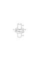
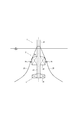
- FIG. 1 is an overall configuration diagram of a spar type floating structure according to the first embodiment of the present invention.
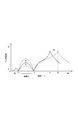
- 2A and 2B are diagrams for explaining the operation of the third expansion portion, in which FIG. 2A shows a normal wave, FIG. 2B shows a high wave, and FIG. 2C shows a wave forcing characteristic curve.
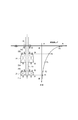
- FIGS. 3A and 3B are diagrams for explaining the operation of the second extension portion, in which FIG. 3A shows a principle explanatory view and FIG. 3B shows a wave forcing force characteristic curve diagram.
- the spar type floating structure 1 includes a floating body portion 2 having an elongated shape, and a ballast portion 3 disposed on the floating body portion 2.
- This is a spar-type floating body structure in which the floating body portion 2 is made to stand upright and float by the weight of the ballast portion 3.
- the floating body 2 includes a first extended portion 21 disposed in the lower portion and expanded in the horizontal direction, a second expanded portion 22 disposed in the intermediate portion and expanded in the horizontal direction, the first expanded portion 21 and the second expanded portion. And a column part 23 that extends to the water line.
- the first extension part 21 constitutes the ballast part 3
- the second extension part 22 constitutes a buoyancy body that gives buoyancy to the floating body part 2.
- the spar type floating structure 1 is, for example, a floating structure for offshore wind power generation, and includes a support column 91, a nacelle 92, and a blade 93 as the upper structure 9.
- the support column 91 is erected on the upper part of the floating body 2 and supports the nacelle 92 and the blade 93.
- the nacelle 92 has a generator inside, and generates electric power by the rotation of the blade 93.
- the blade 93 is rotationally driven by wind power.
- a solar panel 94 may be arranged on the support column 91. By arranging such a solar panel 94, a combined power generation facility using wind power and sunlight can be configured, and the redundancy of the entire structure can be improved.
- the above-described wind power generation equipment is an example of the upper structure 9 installed in the spar type floating structure 1, and is a wind condition observation device such as an anemometer and an anemometer, a solar power generation device, a lighting device, and wireless communication.
- a device or the like may be installed.
- the column portion 23 is a part of a buoyant body that gives buoyancy to the floating body portion 2 and has a hollow cylindrical shape including a draft D.
- the column portion 23 constitutes a shaft portion of the floating body portion 2.
- the column portion 23 has a shape that is reduced in the horizontal direction as compared with the first extension portion 21 and the second extension portion 22, that is, a shape having a smaller diameter than the first extension portion 21 and the second extension portion 22.
- a ballast tank for pouring and draining ballast water and adjusting the weight of the floating body portion 2 may be disposed in a part of the column portion 23.
- the floating body portion 2 has a third extension portion 24 that is arranged on the upper portion of the column portion 23 and extended in the horizontal direction. That is, the third extended portion 24 is formed with a larger diameter than the column portion 23.
- the third extension portion 24 has a hollow cylindrical shape and constitutes a part of a buoyancy body that gives buoyancy to the floating body portion 2.
- the third extended portion 24 is a portion that is exposed to the water line during normal waves.
- the third extension 24 constitutes a pedestal that connects the support column 91 of the upper structure 9.
- a columnar member (a column 91) that is reduced in the horizontal direction is connected to the upper portion of the third extension portion 24.
- the upper surface of the third extension 24 constitutes a work table for performing the installation of the upper structure 9 and the maintenance of the floating body 2.
- a mooring line 25 for mooring the floating body portion 2 is connected to the third extension portion 24.
- the floating body 2 is configured such that the water line is located on the peripheral surface of the third expansion portion 24 during normal waves. Similarly, the water line is located on the peripheral surface of the third extension portion 24 when the wave is calmer than the normal wave. Further, as shown in FIG. 2B, the floating body 2 is configured such that the water line is located on the peripheral surface of the support column 91 on the upper part of the third extension 24 at the time of high wave height. In the case of high waves and low times, the draft line is located on the peripheral surface of the column portion 23 below the third extension portion 24. Therefore, as shown in FIG. 2A and FIG. 2B, the water line area Sa in the normal wave is configured to be larger than the water line area Sb in the high wave.
- the vertical oscillation synchronization period of the floating body 2 is uniquely determined by the structure of the floating body 2, and when the synchronization period and the wave period coincide with each other, the floating body 2 resonates and generates a large vertical oscillation.
- the horizontal axis indicates the period T (s)
- the vertical axis indicates the wave forcing force F.
- the wave forcing force F is a forced external force in the vertical direction caused by the wave, and is made dimensionless here.
- periods T1 and T2 are waveless points where the wave forcing force F is not generated.
- the normal wave has a period within the range of the period T1 to the period T2.
- the period T3 is a tuning period that causes resonance.
- the tuning period is longer than the period T 1 to T 2 in the normal wave so that the tuning period changes from the period T 3 to the period T 4. It is preferable to shift in this direction.
- the tuning period is inversely proportional to the waterline area. That is, increasing the tuning period is equivalent to reducing the waterline area.
- the vertical swing at the normal wave time range of the period T1 to T2 becomes large. Arise. Therefore, there is a demand to increase the waterline area during normal waves.
- the third extension 24 is formed in the upper portion of the column portion 23, the water line at the time of normal wave is located at the third extension 24, and the water line at the time of high wave is a column 91.
- the floating body 2 having a large water line area Sa during normal waves and a small water line area Sb during high waves can be formed by being configured to be positioned in the column part 23. With this configuration, it is possible to suppress resonance during high waves while reducing vertical vibration during normal waves.
- the third extended portion 24 has a water line area Sa having a size of 10 to 300% with respect to the average area Sav obtained by the drainage volume droop / draft D of the floating body portion 2, for example.
- the water line area Sa is set within a range of 17 to 170 m 2 on condition that the water line area Sa is larger than the water line area Sb.
- the specific ratio or numerical value of the waterline area Sa is set in consideration of the amount of drainage ⁇ of the floating body 2, the balance with the waterline area Sb, and the environment of the installation sea area (changes in wave period, amplitude, etc.).
- the first expansion portion 21 is disposed at the lowermost end of the column portion 23 and constitutes the ballast portion 3.
- the first expansion portion 21 may be a ballast portion 3 constituted by a fixed ballast that loads a constant weight on the floating body portion 2, and can adjust the weight of the floating body portion 2 by pouring and draining ballast water.
- the ballast part 3 comprised by the ballast tank which was made, and the ballast part 3 which combined the fixed ballast and the ballast tank may be sufficient.
- the second expansion portion 22 is disposed in the column portion 23 between the first expansion portion 21 and the third expansion portion 24.
- the second expanded portion 22 having a shape expanded in the horizontal direction in the middle portion of the column portion 23, that is, a shape having a diameter larger than that of the column portion 23, a resistance surface against wave up and down is provided.
- a plurality of points can be formed, and a waveless point that is not affected by the wave forcing force can be formed effectively.
- the vertical swing of the floating body 2 can be effectively reduced.
- the floating body 2 includes a lower surface 21a (area S1) and an upper surface 21b (area S2) of the first expansion portion 21, and a lower surface 22a (area S3) and an upper surface 22b (area) of the second expansion portion 22. S4) and five resistance surfaces of the lower surface 24a (area S5) of the third extension 24.
- Each lower surface 21a, 22a, 24a forms a resistance surface against the wave forcing force generated in the upward direction
- each upper surface 21b, 22b forms a resistance surface against the wave forcing force generated in the downward direction.
- the wave forcing force F tends to increase as the water depth decreases and decrease as the water depth increases.
- the wave forcing force at the water depth of the lower surface 21a of the first expansion portion 21 is F1
- the wave forcing force at the water depth of the upper surface 21b is F2
- the wave forcing force at the water depth of the lower surface 22a of the second expansion portion 22 is F3
- the wave forcing force at the water depth is F4
- the wave forcing force at the water depth of the lower surface 24a of the third extension 24 is F5.
- the inclined surfaces for example, the upper surfaces 21b and 22b
- the wave forcing force at the average water depth is illustrated for convenience.
- the pressure generated on the lower surface 21a of the first expansion portion 21 is S1 ⁇ F1
- the pressure generated on the lower surface 22a of the second expansion portion 22 is S3 ⁇ F3
- the pressure generated on the lower surface 24a of the third expansion portion 24 is S5 ⁇ F5.
- the pressure generated on the upper surface 21b of the first expansion portion 21 is S2 ⁇ F2
- the pressure generated on the upper surface 22b of the second expansion portion 22 is S4 ⁇ F4.
- waveless points Z1 and Z2 where the wave forcing force F does not occur can be formed in a certain period (for example, periods T1 and T2).
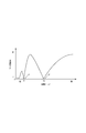
- the horizontal axis and the vertical axis are the same as the parameters shown in FIG.
- KB means the buoyancy height (see FIG. 1)
- BM means the metacenter radius
- KG means the center of gravity height (see FIG. 1).
- Ix means the moment of inertia around the floating body center line on the water surface.
- the metacenter height GM is one parameter indicating the restoration performance.
- the GM is large, the spar type floating structure 1 is difficult to tilt and easily returns to its original state.
- the GM is small, the spar type floating structure 1 is easily tilted and returns slowly. It shows the property.
- the pitching or rolling period is shortened, resulting in vibrations that vibrate finely.
- the large 2nd expansion part 22 approaches the water surface, it will become easy to receive to the influence of a wave forcing force. Therefore, with the buoyancy height KB as large as possible and the center of gravity height KG as low as possible, the buoyancy height is set so as to have a restoration performance equal to or higher than the conventional one while suppressing the drainage amount ⁇ of the floating body 2.
- the positions of KB and center of gravity height KG are determined.
- the second expansion portion 22 is gradually raised upward from a state close to the first expansion portion 21, which is optimal for reducing fluctuations.
- the positions of the floating height KB and the center-of-gravity height KG may be determined.
- the second extension portion 22 is located at a substantially central portion of the draft D, and is set to a position that can include the floating height KB or the center of gravity height KG.
- the second expansion portion 22 has a volume of 20 to 80%, preferably a volume of 1/4 to 3/4, for example, with respect to the drainage volume of the floating body portion 2.
- the second extension 22 is formed in a size that does not interfere with the mooring line 25. This is because when the mooring line 25 and the second extension portion 22 interfere with each other, the mooring line 25 is worn or cut.
- the horizontal size of the second extension portion 22 (in the case of a cylindrical shape) Can determine the diameter or radius), and can also determine the height (vertical width) of the second extension 22.
- a fair leader 26 for guiding the mooring line 25 of the floating body portion 2 is disposed on the side surface of the second extension portion 22.
- the fair leader 26 includes, for example, a pair of arms connected to the side surface of the second extension 22, and has a configuration in which a roller is rotatably supported by the arms.
- the mooring line 25 is inserted between the side surface of the second extension portion 22 and the roller.
- the fair leader 26 is arrange
- the point of action on the floating body 2 due to ocean currents and tidal currents is generally located near the center of the draft D.
- the fair leader 26 by disposing the fair leader 26 at a position that coincides with such an action point, the floating body 2 can be effectively supported by the mooring cable 25, and the influence of ocean currents and tidal currents can be minimized.
- the illustrated configuration of the fair leader 26 is merely an example, and various configurations can be applied.
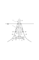
- FIG. 4 is a figure which shows the spar type
- FIG. 4A has shown 2nd embodiment
- FIG. 4B has shown 3rd embodiment.
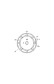
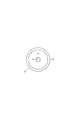
- 5A and 5B are explanatory diagrams of the resistor shown in FIG. 4B.
- FIG. 5A is a top view
- FIG. 5B is a cross-sectional view of a modification
- FIG. 5C is a top view of the modification.
- symbol is attached
- the spar type floating structure 1 according to the second embodiment shown in FIG. 4A is obtained by omitting the third extension 24 in the spar type floating structure 1 according to the first embodiment.
- the first extension portion 21 and the second extension portion 22 are arranged in the floating body 2 and the third extension portion 24 is omitted, at least the effect when the second extension portion 22 is formed is obtained.
- the spar type floating body structure 1 according to the third embodiment shown in FIG. 4B is the spar type floating body structure 1 according to the first embodiment.
- a resistor 27 for adjusting the above is disposed. 4B and 5A, for example, the resistor 27 includes a plurality of fins 271 arranged so as to extend radially from the side surface of the first extension portion 21, and a bottom portion of the first extension portion 21. It has a bilge keel 272 projecting in an annular shape in the horizontal direction and an annular guard member 273 that suppresses the entrainment of the mooring line 25 of the floating body 2.
- the yawing (rotation) of the floating body 2 can be suppressed by the fins 271.
- the fins 271 are, for example, a fin body part 271a connected so that a surface is arranged in the vertical direction on the side surface of the first extension part 21, an outer edge part 271b connected so as to surround the outer periphery of the fin body part 271a,
- the fins 271 are, for example, a fin body part 271a connected so that a surface is arranged in the vertical direction on the side surface of the first extension part 21, an outer edge part 271b connected so as to surround the outer periphery of the fin body part 271a,
- the bilge keel 272 can form a resistance surface against the vertical swing of the floating body 2.
- the bilge keel 272 may be omitted in some cases.
- the guard member 273 on the upper surface and the outer edge portion of the fin 271, the mooring line 25 can be prevented from entering between the fins 271.
- the modification of the resistor 27 shown in FIGS. 5B and 5C is such that the resistor 27 is composed only of the bilge keel 272.
- the bilge keel 272 in this modified example is configured by a plate member having a conical surface inclined obliquely downward from the bottom of the first extension portion 21. Further, the space surrounded by the conical surface of the bilge keel 272 forms a recess, and the surrounding fluid can be retained in this space, and the resistance against the vertical swing of the floating body 2 can be effectively increased.
- the present invention is not limited to the above-described embodiment, and the shapes of the first extension portion 21, the second extension portion 22, and the third extension portion 24 can be appropriately changed within a range that satisfies the above-described conditions.
- various modifications can be made without departing from the spirit of the invention.
Landscapes
- Engineering & Computer Science (AREA)
- Chemical & Material Sciences (AREA)
- Combustion & Propulsion (AREA)
- Mechanical Engineering (AREA)
- Ocean & Marine Engineering (AREA)
- Architecture (AREA)
- Civil Engineering (AREA)
- Structural Engineering (AREA)
- Life Sciences & Earth Sciences (AREA)
- Sustainable Development (AREA)
- Sustainable Energy (AREA)
- General Engineering & Computer Science (AREA)
- Physics & Mathematics (AREA)
- Fluid Mechanics (AREA)
- Wind Motors (AREA)
- Other Liquid Machine Or Engine Such As Wave Power Use (AREA)
Abstract
Description
2 浮体部
3 バラスト部
21 第一拡張部
22 第二拡張部
23 コラム部
24 第三拡張部
25 係留索
26 フェアリーダ
27 抵抗体
91 支柱(柱状部材)
273 ガード部材
Claims (10)
- 細長い形状を有する浮体部と、該浮体部に配置されるバラスト部と、を有し、前記バラスト部の重量によって前記浮体部を直立させて浮遊させるスパー型浮体構造物において、
前記浮体部は、下部に配置され水平方向に拡張された第一拡張部と、中間部に配置され水平方向に拡張された第二拡張部と、前記第一拡張部及び前記第二拡張部を連結するとともに喫水線まで延伸されたコラム部と、を有し、
前記第一拡張部は、前記バラスト部を構成し、
前記第二拡張部は、前記浮体部に浮力を与える浮力体を構成しているスパー型浮体構造物。 - 前記浮体部は、前記コラム部の上部に配置され水平方向に拡張された第三拡張部を有する請求項1に記載のスパー型浮体構造物。
- 前記第三拡張部は、前記浮体部の排水容積/喫水により求められる平均面積に対して10~300%の大きさの水線面積を有する請求項2に記載のスパー型浮体構造物。
- 前記第三拡張部の上部には、水平方向に縮小された柱状部材が接続される請求項2に記載のスパー型浮体構造物。
- 前記第三拡張部には、前記浮体部を係留する係留索が接続される請求項2に記載のスパー型浮体構造物。
- 前記第二拡張部は、前記浮体部の排水容積に対して1/4~3/4の容積を有する請求項1に記載のスパー型浮体構造物。
- 前記第二拡張部の側面には、前記浮体部の係留索を案内するフェアリーダが配置されている請求項6に記載のスパー型浮体構造物。
- 前記第一拡張部及び前記第二拡張部の大きさは、GM=Iw/(Δ×tanθ)の条件(ただし、GMはメタセンタ高さ、Iwは風転倒モーメント、Δは排水量、θは最大許容傾斜角度、を意味する)を満たすように設定される請求項1に記載のスパー型浮体構造物。
- 前記第一拡張部の外面には、前記浮体部の動的応答特性を調整する抵抗体が配置されている請求項1に記載のスパー型浮体構造物。
- 前記抵抗体は、前記浮体部の係留索の巻き込みを抑制する環状のガード部材を有する請求項9に記載のスパー型浮体構造物。
Priority Applications (7)
| Application Number | Priority Date | Filing Date | Title |
|---|---|---|---|
| ES12754705.7T ES2654602T3 (es) | 2011-03-07 | 2012-03-06 | Estructura flotante de tipo mástil |
| JP2013503553A JP5697117B2 (ja) | 2011-03-07 | 2012-03-06 | スパー型浮体構造物 |
| KR1020137024657A KR20130122801A (ko) | 2011-03-07 | 2012-03-06 | 스파형 부체 구조물 |
| EP12754705.7A EP2684792B1 (en) | 2011-03-07 | 2012-03-06 | Spar type floating structure |
| KR1020157018369A KR101621806B1 (ko) | 2011-03-07 | 2012-03-06 | 스파형 부체 구조물 |
| US14/003,634 US9132894B2 (en) | 2011-03-07 | 2012-03-06 | Spar-type floating structure |
| CN201280022023.1A CN103517850B (zh) | 2011-03-07 | 2012-03-06 | 柱型浮体结构物 |
Applications Claiming Priority (2)
| Application Number | Priority Date | Filing Date | Title |
|---|---|---|---|
| JP2011049283 | 2011-03-07 | ||
| JP2011-049283 | 2011-03-07 |
Publications (1)
| Publication Number | Publication Date |
|---|---|
| WO2012121247A1 true WO2012121247A1 (ja) | 2012-09-13 |
Family
ID=46798205
Family Applications (1)
| Application Number | Title | Priority Date | Filing Date |
|---|---|---|---|
| PCT/JP2012/055676 Ceased WO2012121247A1 (ja) | 2011-03-07 | 2012-03-06 | スパー型浮体構造物 |
Country Status (7)
| Country | Link |
|---|---|
| US (1) | US9132894B2 (ja) |
| EP (1) | EP2684792B1 (ja) |
| JP (1) | JP5697117B2 (ja) |
| KR (2) | KR101621806B1 (ja) |
| CN (1) | CN103517850B (ja) |
| ES (1) | ES2654602T3 (ja) |
| WO (1) | WO2012121247A1 (ja) |
Cited By (9)
| Publication number | Priority date | Publication date | Assignee | Title |
|---|---|---|---|---|
| FR2998338A1 (fr) * | 2012-11-22 | 2014-05-23 | IFP Energies Nouvelles | Eolienne offshore comportant un support flottant optimise |
| JP2015009591A (ja) * | 2013-06-26 | 2015-01-19 | ジャパンマリンユナイテッド株式会社 | 浮体構造物 |
| US20150042095A1 (en) * | 2013-08-06 | 2015-02-12 | Hangzhou Lhd Institute Of New Energy, Llc | Tidal Current Generating Device and Installation Frame Thereof |
| CN104925231A (zh) * | 2015-06-29 | 2015-09-23 | 中国能源建设集团广东省电力设计研究院有限公司 | 浮式风机基础及浮式风电机组 |
| JP2016519247A (ja) * | 2013-05-17 | 2016-06-30 | イエフペ エネルジ ヌヴェルIfp Energies Nouvelles | 減衰手段の組み合わせを有する浮体式洋上風力タービン |
| JP2017521296A (ja) * | 2014-05-27 | 2017-08-03 | エステイコ・ソシエダッド・アノニマ・プロフェシオナルEsteyco S.A.P. | 浮体式構造物及び浮体式構造物の設置方法 |
| US10280901B2 (en) | 2014-12-17 | 2019-05-07 | Hitachi, Ltd. | Wind power generation system |
| CN110185585A (zh) * | 2019-05-29 | 2019-08-30 | 中国石油大学(华东) | 一种半潜式垂直轴风力机平台减摇平衡装置 |
| KR20230057377A (ko) * | 2020-09-08 | 2023-04-28 | 알더블유이 리뉴어블스 게엠베하 | 부유식 해상 풍력 터빈 |
Families Citing this family (16)
| Publication number | Priority date | Publication date | Assignee | Title |
|---|---|---|---|---|
| CN105116594B (zh) * | 2015-06-26 | 2018-07-20 | 武汉华星光电技术有限公司 | 背光模组及液晶显示器 |
| SE539182C2 (en) * | 2015-07-02 | 2017-05-02 | Seatwirl Ab | Floating wind energy harvesting apparatus with replaceable energy converter |
| CN105438411B (zh) * | 2015-11-16 | 2017-06-09 | 中国能源建设集团江苏省电力设计院有限公司 | 一种可拖航的海上风电spar浮式基础 |
| US10459155B2 (en) * | 2016-06-28 | 2019-10-29 | Radiant Opto-Electronics (Suzhou) Co., Ltd. | Backlight module and display device having the same |
| WO2019114691A1 (zh) * | 2017-12-15 | 2019-06-20 | 上海海事大学 | 组合式海上风力机支撑结构体系 |
| CN107965422B (zh) * | 2017-12-15 | 2019-05-24 | 上海海事大学 | 一种悬链线型组合式海上风力机支撑结构体系 |
| US10526056B1 (en) * | 2019-04-29 | 2020-01-07 | Physician Electronic Network, LLC | Generation of electric power using wave motion, wind energy and solar energy |
| CN110371251A (zh) * | 2019-07-11 | 2019-10-25 | 上海交通大学 | 一种新型的漂浮式单立柱风电机系泊装置 |
| KR102107994B1 (ko) * | 2019-08-14 | 2020-05-07 | 주식회사 에이스이앤티 | 해상 풍력발전 부유체 |
| CN110712724A (zh) * | 2019-10-15 | 2020-01-21 | 天津大学 | 一种具有高度自稳性的浮式风机平台 |
| JP7519789B2 (ja) * | 2020-03-11 | 2024-07-22 | ジャパンマリンユナイテッド株式会社 | 浮体構造物及び洋上施設 |
| CN113266523B (zh) * | 2021-04-25 | 2022-05-03 | 明阳智慧能源集团股份公司 | 漂浮式双叶轮风电机组波浪扰动的前馈控制方法与系统 |
| CN113331104B (zh) * | 2021-06-23 | 2025-05-13 | 上海勘测设计研究院有限公司 | 一种近海围网养殖装置及其构建方法 |
| CN114382659B (zh) * | 2022-01-27 | 2024-11-15 | 中国华能集团清洁能源技术研究院有限公司 | 漂浮式风力发电机及其压舱装置和压舱装置的控制方法 |
| CN114771759B (zh) * | 2022-05-12 | 2024-08-23 | 中海石油(中国)有限公司 | 一种适用于大兆瓦机组的浮力偏心式半潜漂浮式风机基础 |
| CN115977886A (zh) * | 2023-02-28 | 2023-04-18 | 中国电建集团中南勘测设计研究院有限公司 | 一种适应深远海安装的漂浮式风机基础 |
Citations (5)
| Publication number | Priority date | Publication date | Assignee | Title |
|---|---|---|---|---|
| JP2002188557A (ja) * | 2000-12-18 | 2002-07-05 | Mitsui Eng & Shipbuild Co Ltd | 浮体式風力発電装置及びその設置方法 |
| JP2005069025A (ja) * | 2003-08-27 | 2005-03-17 | Mitsui Eng & Shipbuild Co Ltd | 洋上風力発電装置の基礎構造及び設置方法 |
| JP2005180351A (ja) * | 2003-12-19 | 2005-07-07 | Yoshiro Shinoda | 水上用風力発電装置 |
| JP2009018671A (ja) | 2007-07-11 | 2009-01-29 | Penta Ocean Construction Co Ltd | 洋上風力発電のスパー型浮体構造およびその製造方法 |
| JP2009248792A (ja) | 2008-04-08 | 2009-10-29 | Penta Ocean Construction Co Ltd | 洋上風力発電用のスパー型浮体構造およびその製造方法ならびにその設置方法 |
Family Cites Families (7)
| Publication number | Priority date | Publication date | Assignee | Title |
|---|---|---|---|---|
| JPH0739756Y2 (ja) * | 1987-08-21 | 1995-09-13 | 石川島播磨重工業株式会社 | 浮遊構造物 |
| US6786679B2 (en) * | 1999-04-30 | 2004-09-07 | Abb Lummus Global, Inc. | Floating stability device for offshore platform |
| US20030099516A1 (en) * | 2001-01-02 | 2003-05-29 | Chow Andrew W. | Minimized wave-zone buoyancy platform |
| US8578586B2 (en) * | 2003-10-23 | 2013-11-12 | Shigeyuki Yamamoto | Power generation assemblies, and apparatus for use therewith |
| NO20052704L (no) * | 2005-06-06 | 2006-12-07 | Norsk Hydro As | Flytende vindturbininstallasjon. |
| US8251005B2 (en) * | 2007-04-13 | 2012-08-28 | Shell Oil Company | Spar structures |
| ES2324276B8 (es) * | 2009-03-17 | 2013-11-08 | Investigacion Y Desarrollo De Energias Renovables Marinas, S.L. | Plataforma flotante para la extraccion de energia eolica |
-
2012
- 2012-03-06 ES ES12754705.7T patent/ES2654602T3/es active Active
- 2012-03-06 US US14/003,634 patent/US9132894B2/en active Active
- 2012-03-06 EP EP12754705.7A patent/EP2684792B1/en active Active
- 2012-03-06 CN CN201280022023.1A patent/CN103517850B/zh active Active
- 2012-03-06 JP JP2013503553A patent/JP5697117B2/ja active Active
- 2012-03-06 WO PCT/JP2012/055676 patent/WO2012121247A1/ja not_active Ceased
- 2012-03-06 KR KR1020157018369A patent/KR101621806B1/ko active Active
- 2012-03-06 KR KR1020137024657A patent/KR20130122801A/ko not_active Ceased
Patent Citations (5)
| Publication number | Priority date | Publication date | Assignee | Title |
|---|---|---|---|---|
| JP2002188557A (ja) * | 2000-12-18 | 2002-07-05 | Mitsui Eng & Shipbuild Co Ltd | 浮体式風力発電装置及びその設置方法 |
| JP2005069025A (ja) * | 2003-08-27 | 2005-03-17 | Mitsui Eng & Shipbuild Co Ltd | 洋上風力発電装置の基礎構造及び設置方法 |
| JP2005180351A (ja) * | 2003-12-19 | 2005-07-07 | Yoshiro Shinoda | 水上用風力発電装置 |
| JP2009018671A (ja) | 2007-07-11 | 2009-01-29 | Penta Ocean Construction Co Ltd | 洋上風力発電のスパー型浮体構造およびその製造方法 |
| JP2009248792A (ja) | 2008-04-08 | 2009-10-29 | Penta Ocean Construction Co Ltd | 洋上風力発電用のスパー型浮体構造およびその製造方法ならびにその設置方法 |
Cited By (14)
| Publication number | Priority date | Publication date | Assignee | Title |
|---|---|---|---|---|
| EP2735735A1 (fr) * | 2012-11-22 | 2014-05-28 | IFP Energies nouvelles | Éolienne offshore comportant un support flottant optimisé |
| FR2998338A1 (fr) * | 2012-11-22 | 2014-05-23 | IFP Energies Nouvelles | Eolienne offshore comportant un support flottant optimise |
| JP2016519247A (ja) * | 2013-05-17 | 2016-06-30 | イエフペ エネルジ ヌヴェルIfp Energies Nouvelles | 減衰手段の組み合わせを有する浮体式洋上風力タービン |
| JP2015009591A (ja) * | 2013-06-26 | 2015-01-19 | ジャパンマリンユナイテッド株式会社 | 浮体構造物 |
| US9556848B2 (en) * | 2013-08-06 | 2017-01-31 | Hangzhou Lhd Institute Of New Energy, Llc | Tidal current generating device and installation frame thereof |
| US20150042095A1 (en) * | 2013-08-06 | 2015-02-12 | Hangzhou Lhd Institute Of New Energy, Llc | Tidal Current Generating Device and Installation Frame Thereof |
| JP2017521296A (ja) * | 2014-05-27 | 2017-08-03 | エステイコ・ソシエダッド・アノニマ・プロフェシオナルEsteyco S.A.P. | 浮体式構造物及び浮体式構造物の設置方法 |
| JP2021099021A (ja) * | 2014-05-27 | 2021-07-01 | エステイコ・ソシエダッド・アノニマEsteyco S.A. | 浮体式構造物及び浮体式構造物の設置方法 |
| JP7186406B2 (ja) | 2014-05-27 | 2022-12-09 | エステイコ・ソシエダッド・アノニマ | 浮体式構造物及び浮体式構造物の設置方法 |
| US10280901B2 (en) | 2014-12-17 | 2019-05-07 | Hitachi, Ltd. | Wind power generation system |
| CN104925231A (zh) * | 2015-06-29 | 2015-09-23 | 中国能源建设集团广东省电力设计研究院有限公司 | 浮式风机基础及浮式风电机组 |
| CN110185585A (zh) * | 2019-05-29 | 2019-08-30 | 中国石油大学(华东) | 一种半潜式垂直轴风力机平台减摇平衡装置 |
| KR20230057377A (ko) * | 2020-09-08 | 2023-04-28 | 알더블유이 리뉴어블스 게엠베하 | 부유식 해상 풍력 터빈 |
| KR102592240B1 (ko) | 2020-09-08 | 2023-10-23 | 알더블유이 리뉴어블스 게엠베하 | 부유식 해상 풍력 터빈 |
Also Published As
| Publication number | Publication date |
|---|---|
| EP2684792A4 (en) | 2015-07-29 |
| JP5697117B2 (ja) | 2015-04-08 |
| KR20150088897A (ko) | 2015-08-03 |
| ES2654602T3 (es) | 2018-02-14 |
| EP2684792B1 (en) | 2017-10-04 |
| EP2684792A1 (en) | 2014-01-15 |
| KR101621806B1 (ko) | 2016-05-17 |
| CN103517850A (zh) | 2014-01-15 |
| CN103517850B (zh) | 2016-03-30 |
| US20140026798A1 (en) | 2014-01-30 |
| US9132894B2 (en) | 2015-09-15 |
| JPWO2012121247A1 (ja) | 2014-07-17 |
| KR20130122801A (ko) | 2013-11-08 |
Similar Documents
| Publication | Publication Date | Title |
|---|---|---|
| JP5697117B2 (ja) | スパー型浮体構造物 | |
| JP7186406B2 (ja) | 浮体式構造物及び浮体式構造物の設置方法 | |
| CN103818523B (zh) | 外飘式张力腿浮动风机基础、海上风力发电机及施工方法 | |
| JP7014498B2 (ja) | 浮遊式風力タービン組立体、ならびにそのような浮遊式風力タービン組立体を係留するための方法 | |
| CN105209754B (zh) | 包括冲击吸收装置组合的浮动式装配件上的海上风力涡轮 | |
| JP6366124B2 (ja) | 浮体構造物 | |
| CN204415681U (zh) | 半潜式浮动风机基础和浮动风机 | |
| CN104401458A (zh) | 半潜式浮动风机基础和浮动风机 | |
| WO2018095304A1 (zh) | 一种浮式风机的移动压载调平控制装置 | |
| CN206554109U (zh) | 一种三立柱半潜式海上风机基础 | |
| JP6155326B2 (ja) | 持ち上げられた定着システムによって安定化された浮揚式支持体上の風力タービン | |
| JP5809069B2 (ja) | スパー型浮体構造物 | |
| JP2014061848A (ja) | 浮体構造物およびその動揺低減装置 | |
| JP2014218958A (ja) | 洋上風力発電用浮体構造物 | |
| JP2005180351A (ja) | 水上用風力発電装置 | |
| US20150204045A1 (en) | Floating offshore structures | |
| JP2019521905A (ja) | フロート及び深さとともに変化する断面を有する減衰板を有する浮体式支持構造体 | |
| JP2011251675A (ja) | 減揺装置 | |
| CN112324625A (zh) | 网格化布置的深海漂浮式风机基础 | |
| JP6440597B2 (ja) | 傾斜スパーブイ | |
| US20250137439A1 (en) | Offshore floating wind turbine platform of semi submersible type with columns’ cross-section area expanded up to water surface | |
| JP2016182876A (ja) | 洋上風力発電装置及び洋上風力発電設備 | |
| NO330856B1 (no) | Flytende vindkraftverk |
Legal Events
| Date | Code | Title | Description |
|---|---|---|---|
| WWE | Wipo information: entry into national phase |
Ref document number: 201280022023.1 Country of ref document: CN |
|
| 121 | Ep: the epo has been informed by wipo that ep was designated in this application |
Ref document number: 12754705 Country of ref document: EP Kind code of ref document: A1 |
|
| ENP | Entry into the national phase |
Ref document number: 2013503553 Country of ref document: JP Kind code of ref document: A |
|
| NENP | Non-entry into the national phase |
Ref country code: DE |
|
| REEP | Request for entry into the european phase |
Ref document number: 2012754705 Country of ref document: EP |
|
| ENP | Entry into the national phase |
Ref document number: 20137024657 Country of ref document: KR Kind code of ref document: A |
|
| WWE | Wipo information: entry into national phase |
Ref document number: 14003634 Country of ref document: US |