WO2012124276A1 - 無線映像送信装置および無線映像受信装置ならびにこれらを備えた無線映像伝送システム - Google Patents
無線映像送信装置および無線映像受信装置ならびにこれらを備えた無線映像伝送システム Download PDFInfo
- Publication number
- WO2012124276A1 WO2012124276A1 PCT/JP2012/001437 JP2012001437W WO2012124276A1 WO 2012124276 A1 WO2012124276 A1 WO 2012124276A1 JP 2012001437 W JP2012001437 W JP 2012001437W WO 2012124276 A1 WO2012124276 A1 WO 2012124276A1
- Authority
- WO
- WIPO (PCT)
- Prior art keywords
- video
- wireless
- unit
- video data
- access point
- Prior art date
- Legal status (The legal status is an assumption and is not a legal conclusion. Google has not performed a legal analysis and makes no representation as to the accuracy of the status listed.)
- Ceased
Links
Images


Classifications
-
- H—ELECTRICITY
- H04—ELECTRIC COMMUNICATION TECHNIQUE
- H04N—PICTORIAL COMMUNICATION, e.g. TELEVISION
- H04N21/00—Selective content distribution, e.g. interactive television or video on demand [VOD]
- H04N21/60—Network structure or processes for video distribution between server and client or between remote clients; Control signalling between clients, server and network components; Transmission of management data between server and client, e.g. sending from server to client commands for recording incoming content stream; Communication details between server and client
- H04N21/63—Control signaling related to video distribution between client, server and network components; Network processes for video distribution between server and clients or between remote clients, e.g. transmitting basic layer and enhancement layers over different transmission paths, setting up a peer-to-peer communication via Internet between remote STB's; Communication protocols; Addressing
- H04N21/631—Multimode Transmission, e.g. transmitting basic layers and enhancement layers of the content over different transmission paths or transmitting with different error corrections, different keys or with different transmission protocols
-
- H—ELECTRICITY
- H04—ELECTRIC COMMUNICATION TECHNIQUE
- H04N—PICTORIAL COMMUNICATION, e.g. TELEVISION
- H04N21/00—Selective content distribution, e.g. interactive television or video on demand [VOD]
- H04N21/20—Servers specifically adapted for the distribution of content, e.g. VOD servers; Operations thereof
- H04N21/21—Server components or server architectures
- H04N21/218—Source of audio or video content, e.g. local disk arrays
- H04N21/2187—Live feed
-
- H—ELECTRICITY
- H04—ELECTRIC COMMUNICATION TECHNIQUE
- H04W—WIRELESS COMMUNICATION NETWORKS
- H04W36/00—Hand-off or reselection arrangements
- H04W36/16—Performing reselection for specific purposes
- H04W36/18—Performing reselection for specific purposes for allowing seamless reselection, e.g. soft reselection
-
- H—ELECTRICITY
- H04—ELECTRIC COMMUNICATION TECHNIQUE
- H04W—WIRELESS COMMUNICATION NETWORKS
- H04W36/00—Hand-off or reselection arrangements
- H04W36/24—Reselection being triggered by specific parameters
- H04W36/26—Reselection being triggered by specific parameters by agreed or negotiated communication parameters
- H04W36/28—Reselection being triggered by specific parameters by agreed or negotiated communication parameters involving a plurality of connections, e.g. multi-call or multi-bearer connections
Definitions
- the present invention relates to a wireless video transmission device and a wireless video reception device for transmitting and receiving a video signal by wireless communication while switching a plurality of access points (base stations), and a wireless video transmission system including these.
- a mobile terminal for example, a mobile phone
- a mobile terminal can maintain wireless communication in a wide area by performing a handover for switching a plurality of access points during movement.
- a line condition deteriorates near the boundary of an access point cover area (that is, a range where radio waves reach), or communication is temporarily interrupted when a handover is performed.
- the amount of information to be transmitted is large compared to voice communication or the like, and thus it is indispensable to deal with the above problems in order to realize high transmission quality.
- blocks obtained by dividing still images of each frame of a moving image are classified into blocks of interest and non-blocks of interest according to their importance.
- a technique is known that enables high-quality reproduction of at least the main part of an image even when the communication line condition deteriorates by preferentially reducing the code for the block of interest (see Patent Document 1). ).
- two transmission / reception systems for transmitting / receiving signals to / from the base station are provided, and when performing handover, the transmission / reception system that is not involved in communication with the switching source base station is used.
- a technique is known in which a communication interruption time at the time of handover is shortened by transmitting / receiving a control signal related to handover to / from a switching destination base station (see Patent Document 2).
- Patent Document 1 the conventional technique described in Patent Document 1 is configured to generate one stream by preferentially performing code reduction for non-target blocks in the encoding process.
- the image server transmits to the client device. It is effective for systems that distribute moving images, but can be controlled according to the line conditions when considering application to mobile communications using wireless LAN (Local Area Network) access points. There is a problem that the range of the code amount is small.
- Patent Document 2 in a network with a guaranteed bandwidth such as PHS (Personal Handyphone System), communication interruption time at the time of handover can be shortened by two transmission / reception systems. In the mobile communication using no wireless LAN access point or the like, there is a problem that high quality transmission cannot be expected.
- PHS Personal Handyphone System
- the present invention has been devised in view of such problems of the prior art. Even when the handover is performed or when the line condition deteriorates in the vicinity of the boundary of the access point coverage, the video disturbance and image quality are improved.
- the main object of the present invention is to provide a wireless video transmission device and a wireless video reception device that realize high-quality video data transmission while suppressing a decrease in image quality, and a wireless video transmission system including these.
- the wireless video transmission device includes an imaging unit that captures an image of a subject and generates video data, and priority video data and non-priority video generated based on the video data so that at least an image area or an image resolution is different from each other.
- a data generation unit that generates data, a video encoding unit that encodes the priority video data and the non-priority video data, a first wireless communication unit that communicates with a first access point, and the first access
- a second wireless communication unit that communicates with a second access point that is a point handover destination candidate, and a communication control unit that controls wireless communication by the first and second wireless communication units, the communication control unit Is based on the line status of communication with the first access point and the execution status of the handover to the second access point, Determining whether video streams from the first and second wireless communication units are suitable for transmission, and encoding the priority video data and the non-priority video data as two separate video streams. It transmits from 2 radio
- Schematic configuration diagram of the wireless video transmission system 1 The block diagram which shows the detailed structure of the radio
- an imaging unit that images a subject to generate video data and a priority that is generated based on the video data so that at least an image area or an image resolution is different from each other.
- a data generation unit that generates video data and non-priority video data; a video encoding unit that encodes the priority video data and non-priority video data; and a first wireless communication unit that communicates with a first access point;
- a second wireless communication unit that communicates with a second access point that is a handover destination candidate of the first access point, and a communication control unit that controls wireless communication by the first and second wireless communication units
- the communication control unit includes a line status of communication with the first access point, and an implementation state of handover to the second access point.
- the first and second wireless communication units On the basis of the first and second wireless communication units, and determines whether or not the first and second wireless communication units encode the priority video data and the non-priority video data as two separate video streams.
- 2 is a wireless video transmission apparatus that transmits from a wireless communication unit of FIG.
- priority video data and non-priority video data are transmitted as individual video streams, and whether or not each video stream is transmitted is determined based on the line status and handover execution status.
- the code amount of the video data can be controlled independently, and the range of the code amount that can be controlled in wireless communication can be expanded. Therefore, even when the line condition deteriorates near the boundary of the access point cover area at the time of handover, high-quality video data transmission can be realized while suppressing video disturbance and image quality degradation.
- the second invention relates to the first invention, wherein the communication control unit determines that both of the two video streams are the first when the line status does not satisfy the first criterion related to the propriety of transmission. It is set as the structure which determines transmitting to the said 1st access point from one radio
- the receiving-side apparatus can appropriately use one or both of the priority video data and the non-priority video data as video data for display or the like according to the reception status of each video stream.
- High-quality video data transmission can be realized even when the line condition deteriorates near the boundary of the access point cover area.
- a third invention relates to the second invention, wherein the communication control unit, when the line status does not satisfy a second standard lower than the first standard, one of the two video streams. Is determined to be transmitted from the second wireless communication unit to the second access point.
- the video stream is transmitted before the handover to the second access point that can be the handover destination, high-quality video data can be transmitted even during the handover.
- a fourth invention relates to any one of the first to third inventions, wherein the communication control unit, when the handover from the first access point to the second access point is completed, A configuration in which transmission of the two video streams to one access point is stopped while both of the two video streams are determined to be transmitted from the second wireless communication unit to the second access point; To do.
- the receiving side apparatus can appropriately use one or both of the priority video data and the non-priority video data as video data for display or the like according to the reception status of each video stream, the handover is completed. High-quality video data transmission can be realized even when the line condition deteriorates near the boundary of the cover area of the second access point later.
- a wireless video receiving apparatus that communicates with the wireless video transmitting apparatus according to any one of the first to fourth aspects, wherein the wireless video receiving apparatus communicates with the wireless video transmitting apparatus via the first and second access points.
- a data receiving unit that receives the two video streams transmitted from the video transmitting device and a video decoding unit that decodes video data included in at least one received video stream are provided.
- a plurality of different video data can be appropriately used as video data for display etc. according to the reception status of a plurality of video streams, so when performing handover or near the boundary of the access point cover area Even when the line condition deteriorates, high-quality video data transmission can be realized by suppressing the disturbance of the video and the deterioration of the image quality.
- the sixth invention relates to the fifth invention, and further comprises a handover completion notifying unit for notifying the wireless video receiving apparatus of completion of handover to the second access point.
- the video data transmission side (wireless video transmission device) can surely grasp the timing of completion of handover, it is possible to transmit high-quality video data.
- the seventh invention relates to the fifth or sixth invention, wherein when the data receiving unit receives a plurality of video streams of the same type, the data decoding unit determines whether the video decoding unit receives a plurality of video streams of the same type. The video stream selection unit further selects a stream to be decoded.
- the eighth invention relates to any one of the fifth to seventh inventions, further comprising a display unit, wherein the display position of the priority video during handover is fixed according to the line status.
- a wireless video comprising: the wireless video transmission device according to any one of the first to fourth inventions; and the wireless video reception device according to any of the fifth to eighth inventions. It is a transmission system.
- FIG. 1 is a schematic configuration diagram of a wireless video transmission system 1 according to the present invention.
- the wireless video transmission system 1 includes a wireless camera 2 as a wireless video transmission device that transmits a video signal by wireless communication, and a PC (Personal Computer) as a wireless video reception device that receives the video signal transmitted from the wireless camera 2. 3 mainly.
- the wireless camera 2 is communicably connected to the PC 3 via two access points AP1 and AP2 and an IP (Internet Protocol) network 4.
- the IP network 4 is composed of a LAN (Local Area Network) conforming to a known network standard such as Ethernet (registered trademark), but is not limited thereto, and uses a WAN (Wide-Area Network) or the Internet. You may do it.
- LAN Local Area Network
- Ethernet registered trademark
- WAN Wide-Area Network
- the access points AP1 and AP2 are radio wave repeaters having the same configuration, and wireless communication with the wireless camera 2 is possible.
- the cover areas 5 and 6 of the access points AP1 and AP2 define an area where the wireless camera 2 can communicate, and are set so that some areas near the boundary of each other overlap.
- the wireless camera 2 performs a handover (switches the access points AP1 and AP2 from one to the other), and the PC 3 and Maintain communication.
- FIG. 2 is a block diagram showing a detailed configuration of the wireless video transmission system 1 of FIG. 1
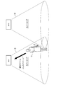
- FIG. 3 is a schematic diagram showing an example of a video stream transmission method in the wireless video transmission system
- FIG. 4 is a video encoding unit.
- 13 is a diagram illustrating a configuration example of data after encoding by 13
- FIG. 5 is a diagram illustrating a configuration example of transmission data by the video transmission unit 14.
- the imaging unit 11 includes a solid-state imaging device such as an optical lens system (not shown) or a CMOS (ComplementarylementMetal Oxide Semiconductor Image Sensor).
- CMOS ComplementarylementMetal Oxide Semiconductor Image Sensor
- a subject image incident on the surface is imaged to generate captured video data (video signal).
- the video cutout unit 12 appropriately cuts out a region of interest (ROI: Region ⁇ of Interest) from the captured video data generated by the imaging unit 11.
- ROI Region ⁇ of Interest
- the user can set a predetermined area in the image as an attention area in advance. Alternatively, the user may set the attention area while watching the video displayed on the video display unit 25 of the PC 3 described later. It is also possible to automatically recognize a moving object such as a person or a car in an image by a known image recognition process without setting the user's operation, and set the area including the moving object as a region of interest. is there.
- the video encoding unit 13 includes the target video data regarding the target region output from the video cutout unit 12 and the captured video data output from the image pickup unit 11 (the target region when the video cutout unit 12 performs cutout).
- Non-focused video data related to a non-focused area including an external stationary background is encoded using a well-known compression coding technique based on MPEG2 (Moving / Picture / Experts / Group / phase-2).
- MPEG2 Moving / Picture / Experts / Group / phase-2).
- the video encoding unit 13 can control the code amount allocation for each pixel block included in the attention area and the non-attention area.
- the attention area and the non-attention area have different image areas, but they are not necessarily exclusive, and a configuration in which a part of them overlaps is possible.
- the video encoding unit 13 performs encoding so as to be a set code amount by a transmission control unit 18 to be described later, but if the generated code amount is large and exceeds the set value, the imaging unit 11, the captured video data output from 11 is reduced to lower the resolution, and then encoding is performed.
- the resolution of the captured video data By reducing the resolution of the captured video data, the amount of generated code can be suppressed, and the amount of code for encoding the non-attention area can be greatly reduced.
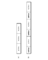
- the captured video data (non-focused video data) input from the imaging unit 11 to the video encoding unit 13 is, for example, an I picture (Intra Picture) or a P picture (Predictive) as shown in FIG.
- the data is output from the video encoding unit 13 as a data string including an image such as “Picture”.
- the target video data input from the video cutout unit 12 to the video encoding unit 13 indicates the position of the target region for each image such as each I picture or P picture, for example, as shown in FIG.
- the data is output from the video encoding unit 13 as a data string to which position information is added.
- the video transmission unit 14 converts each video data encoded by the video encoding unit 13 into an IP packet and outputs it as an individual video stream. That is, as shown in FIG. 3, when clipping is performed by the video clipping unit 12, attention video data regarding a region of interest is used to ensure transmission quality at the time of handover or when the line condition deteriorates. It is transmitted as a priority video stream to be prioritized. On the other hand, non-focused video data related to a non-focused area is transmitted as a non-prioritized video stream that does not need to be prioritized.
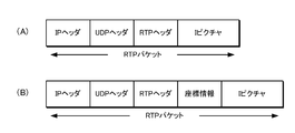
- an image of non-target video data (here, an I picture) input from the video encoding unit 13 to the video transmission unit 14 is, for example, an RTP having a predetermined image size as shown in FIG.
- a header, a UDP header, and an IP header are added to be packetized.
- an image of interest video data (here, an I picture) input from the video encoding unit 13 to the video transmission unit 14 includes, for example, an RTP header and a UDP header together with position information as illustrated in FIG.
- An IP header is added and packetized. It is also possible to preferentially transmit the priority video stream using a QoS guarantee mechanism such as Differentiated Services.
- the first wireless communication unit 15 performs wireless communication conforming to a wireless LAN communication standard such as IEEE 802.11a / b / g with the access point AP1 via an antenna (not shown).
- a wireless LAN communication standard such as IEEE 802.11a / b / g
- Each video data converted into IP packets by the video transmission unit 14 is transmitted from the first wireless communication unit 15 to the PC 3 via the access point AP1.
- the target video data and the video data (non-target video data) output from the imaging unit 11 are transmitted as individual video streams.
- the first wireless communication unit 15 can detect the received signal strength that serves as an index for grasping the channel status of wireless communication.
- the second wireless communication unit 16 has the same configuration and function as the first wireless communication unit 15.
- Second wireless communication unit 16 presets the existence of an access point (here, access point AP2) that can be a handover destination different from the access point (here, access point AP1) with which first wireless communication unit 15 is communicating.
- the wireless communication is performed with the access point that is the handover destination candidate.
- the second wireless communication unit 16 measures the received signal strength at the time of detecting the access point, and if there are a plurality of AP2 candidates at the time of handover described later, the second wireless communication unit 16 receives more based on the measurement result of the received signal strength. It operates to select AP2 having a large signal strength.
- the first wireless communication unit 15 and the second wireless communication unit 16 perform functions opposite to each other.
- the communication control unit 17 performs overall control of communication in the wireless video transmission system 1 including control of wireless communication by the first and second wireless communication units 15 and 16.
- the transmission control unit 18 controls the transmission of each video data to the PC 3 by controlling the operations of the video clipping unit 12 and the video encoding unit 13.
- the transmission mode determination unit 19 also sets a plurality of preset operation modes to be executed by the wireless camera 2 in order to realize high-quality video data transmission based on the wireless communication line status and handover execution status. The operation mode is determined. Thereby, the transmission control part 18 controls transmission of each video data according to the determined operation mode.
- the NW (network) communication unit 21 is connected to the access points AP1 and AP2 via the IP network 4, and is based on a well-known protocol such as the TCP / IP protocol. 2 transmits / receives a video stream and various control information.
- the video receiving unit 22 has a buffer function for accumulating received data, and outputs the encoded video data included in the IP packet received from the wireless camera 2 by the NW communication unit 21 to the video decoding unit 23. To do.
- the video decoding unit 23 decodes each video data from the video receiving unit 22.
- the attention video data decoded here and the non-attention video data corresponding thereto are synthesized by the video synthesis unit 24 as necessary, as shown in FIG.
- the video data acquired in this way is displayed on the video display unit 25 having a liquid crystal display or the like.
- the position of the region of interest displayed on the video display unit 25 may be fixed when performing a handover described later.
- the display position of the attention area can be designated from the wireless camera 2 side when the priority video stream is transmitted. This makes it possible for the user to recognize that the handover is in progress and improves the visibility of the attention area during the handover.
- whether or not the position of the attention area needs to be fixed can be determined according to the magnitude of the received signal strength in the wireless camera 2, for example, when the received signal strength is smaller than a preset threshold value. Only the position of the attention area should be fixed. As a result, when the received signal strength is high, the position of the region of interest is not fixed even during handover, so that more natural video display is possible.
- the reception control unit 26 controls the operation of the video reception unit 22, the video decoding unit 23, and the video synthesis unit 24 to control the reception and display of each video data with respect to the PC 3.
- the stream selection unit 27 cooperates with the reception control unit 26 and receives a plurality of the same kind of video streams by the video reception unit 22 (that is, from the first and second wireless communication units 15 and 16 of the wireless camera 2).
- the video decoding unit 23 selects a video stream to be decoded according to the reception status of each video stream.
- the PC 3 includes a CPU (Central Processing Unit), a ROM (Read Only Memory), a RAM (Random Access Memory), an input / output interface, and the like. This process can be realized.
- CPU Central Processing Unit
- ROM Read Only Memory
- RAM Random Access Memory
- the communication control unit 17 determines whether transmission from the first and second wireless communication units 15 and 16 is appropriate for each video stream based on the wireless communication line status and handover execution status. To do.
- the determination of the propriety of transmission of each video stream by the communication control unit 17 is realized by selectively executing the following three operation modes.
- the three operation modes of the wireless camera 2 are one stream mode in which the captured video data output from the imaging unit 11 is transmitted as a single video stream from the first wireless communication unit 15 to the access point AP1, and attention 2-stream mode A (no handover) for transmitting a priority video stream including video data and a non-priority video stream including non-target video data from the first wireless communication unit 15 to the access point AP1, and priority including target video data
- 2-stream mode B Ha Consisting of Dooba there
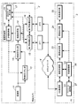
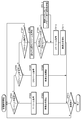
- FIG. 6 is a flowchart showing video stream transmission operation by the wireless camera 2
- FIG. 7 is an explanatory diagram of video stream transmission in the 2-stream mode A (no handover) of the wireless camera 2
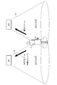
- FIG. It is explanatory drawing of the video stream transmission in 2 stream mode B (with a hand-over).
- the first wireless communication unit 15 When the wireless camera 2 is activated, first, the first wireless communication unit 15 is connected to the access point AP1 corresponding to the cover area 5 to which the current position belongs, as shown in FIG.
- the second radio communication unit 16 that does not need to communicate at the present time (that is, communicates with the access point AP2 that is the handover destination later) detects the received signal strength of the access point AP1 (ST101).
- the first wireless communication unit 15 may be configured to detect the received signal strength of AP1.
- the transmission mode determination unit 19 determines that the wireless communication channel status is good. 1 stream mode is implemented.
- the transmission mode determination unit 19 It is determined that the situation is getting worse, and the 2-stream mode A is performed.
- the transmission mode determination unit 19 determines that the wireless communication channel status has deteriorated to the extent that handover is required. Then, 2 stream mode B (with handover) is performed.
- the region-of-interest segmenting operation by the image segmenting unit 12 is stopped (ST103).
- the captured video data output from the imaging unit 11 is encoded as it is in the video encoding unit 13 (ST104), and one video stream is sent from the first wireless communication unit 15 to the PC 3 via the access point AP1. (ST105).
- the current position of the wireless camera 2 is located in a relatively cheap place (such as near the center) within the cover area 5. Even when the code amount is not reduced by cutting out the region of interest, a sufficient transmission band can be secured.
- the region-of-interest segmenting operation by the image segmenting unit 12 is started (ST106).
- the video encoding unit 13 encodes the target video data and the non-target video data (ST107), and the first wireless communication unit 15 via the access point AP1 as the priority video stream and the non-priority video stream, respectively. Is transmitted to the PC 3 (ST108).
- the current position of the wireless camera 2 is in a place where the radio wave is relatively difficult to reach within the cover area 5 (such as near the boundary).
- the PC 3 can appropriately use one or both of the priority video stream and the non-priority video stream transmitted from the wireless camera 2 as video data for display or the like, high quality even when the line condition deteriorates Video data transmission can be realized.
- steps ST109 and ST110 similar to steps ST106 and ST107 described above are performed, respectively.
- the transmission control unit 18 executes step ST112 similar to the above-described step ST108, and further accesses from the second wireless communication unit 16. Only the priority video stream is transmitted to the PC 3 via the point AP2 (ST113). Note that if the handover completion notification is not received from the PC 3 within a predetermined time predetermined by the user, the transmission control unit 18 is not in a position where the wireless camera 2 can be handed over (that is, all access points). It is possible to display an error to the user by determining that the user has moved out of the cover area.
- the transmission control unit 18 stops transmission of the priority video stream and the non-priority video stream from the first wireless communication unit 15 started in step ST112 ( ST114). Subsequently, the transmission control unit 18 transmits a non-priority video stream in addition to the priority video stream from the second wireless communication unit 16 to the PC 3 via the access point AP2 (ST115).
- the current position of the wireless camera 2 is at the boundary between both cover areas where the cover area 5 and the cover area 6 overlap.
- the priority-reduced video stream with the code reduced is transmitted to the second access point that can be the handover destination, high-quality video data transmission can be realized even during the handover.
- the PC 3 appropriately uses one or both of attention video data (priority video data) and non- attention video data (non-priority video data) as video data for display or the like according to the reception status of each video stream. Therefore, even when the line condition deteriorates near the boundary of the coverage area of the second access point after the handover is completed, high-quality video data transmission can be realized.
- the wireless camera 2 transmits the priority video data and the non-priority video data as individual video streams, and determines whether the transmission of each video stream is appropriate based on the line status and the handover execution status.
- the code amounts of the video data and the non-priority video data can be controlled independently, and the range of the code amount that can be controlled in wireless communication can be expanded. Therefore, even when the line condition deteriorates near the boundary of the access point cover area at the time of handover, high-quality video data transmission can be realized while suppressing video disturbance and image quality degradation.
- step ST114 it is also possible to stop transmission of only the non-priority video stream (that is, transmit only the priority video stream).
- only specific video data for example, I picture
- by continuing the transmission of the video data to the handover source there is an advantage that high quality video data transmission can be secured even when the handover to the access point AP1 is performed again.
- step 112 it is also possible to transmit only the priority video stream.
- only specific video data for example, I picture
- I picture different from the handover destination
- step ST113 only the priority video stream is transmitted from the second wireless communication unit 16 to the PC 3, but a necessary transmission band cannot be secured for the priority video stream, and the non-priority video stream is not transmitted. If the code amount is smaller, only the non-priority video stream can be transmitted. Details of the modified example regarding step ST113 will be described with reference to FIG.
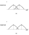
- FIG. 9 is an explanatory diagram showing the relationship between the distance between the access points AP1 and AP2 and the received signal strength in the wireless video transmission system 1.
- (A) shows a case where the distance between the access points is small
- (B) shows a case where the distance between the access points is large.
- the distance between the access points AP1 and AP2 is relatively small, and the received signal strength is relatively large (that is, the available bandwidth that can be secured is relatively large) in the overlapping region (see the shaded area). Large) is suitable for transmitting the priority video stream.
- the distance between the access points AP1 and AP2 is relatively large, and the received signal strength is relatively small in the overlapping area (see the shaded area) (that is, the available bandwidth that can be secured is small). (Relatively small) is suitable for transmitting non-priority video streams. In this way, even in the case of an available band where the priority video stream cannot be transmitted, there is an advantage that the interruption of the video can be reduced by transmitting the non-priority video stream.
- the transmission mode is determined using the received signal strength related to AP1, but the received signal strength related to AP2 can also be used. For example, when the reception strength of AP2 is higher than the reception strength of AP1, it is possible to control to switch the transmission destination to AP2 in the 1-stream mode without going through the 2-stream mode.
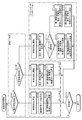
- FIG. 10 is a flowchart showing an operation of receiving a video stream by the PC 3.
- the stream selection unit 27 determines whether or not only one video stream is received in the video reception unit 22 (ST201).
- the video stream is decoded by the video decoding unit 23 (ST202).
- the video is displayed on the video display unit 25 without undergoing the synthesis process by the video synthesis unit 24 (ST203).
- the stream selection unit 27 further determines whether two video streams are received by the video reception unit 22 (ST204). .
- these video streams are respectively decoded by the video decoding unit 23 (ST205).
- the decoded attention video data and the non-target video data corresponding thereto are synthesized by the video synthesis unit 24 (ST206) and displayed on the video display unit 25.
- the stream selection unit 27 further determines whether or not three video streams are received in the video reception unit 22 (ST207). .
- the stream selection unit 27 displays the two priority videos included in the video streams.
- One of the streams (the same kind of video stream) is selected as a video stream to be decoded by the video decoding unit 23 according to the reception status of the priority video streams (for example, using packet loss rate and jitter fluctuation as an index). (ST208).
- the frequency of syntax errors at the time of decoding may be used as an indicator of the quality of the reception status.
- the stream selection unit 27 determines whether or not one of the priority video streams selected in step ST208 has been sent to the handover destination (ST209), and if it has not been sent to the handover destination (No), Steps ST210 and ST211 similar to Steps ST205 and ST206 described above are executed.
- the reception control unit 26 indicates that the handover has been completed for the wireless camera 2 before executing steps ST210 and ST211.
- a handover completion notification for notification is transmitted (ST212).
- the wireless camera 2 can reliably grasp the timing of completion of the handover, so that high-quality video data can be transmitted.
- the wireless video transmission device is not limited to the above-described wireless camera, and may be any device that has at least a wireless communication function and a video data transmission function.
- the wireless video receiving apparatus is not limited to the above-described PC, and any wireless video receiving apparatus may be used as long as it has a function of receiving video data from at least the wireless video transmitting apparatus and decoding the received video data.
- the priority video data (notice video data) and the non-priority video data (non-note video data) having different image areas are generated by cutting out the attention area.
- a scalable codec such as H.264 SVC for conversion
- the attention area is encoded with high image quality
- the non- attention area is encoded with low image quality
- the attention area is reduced.
- the components of the wireless video transmission device and the wireless video reception device and the wireless video transmission system including the wireless video transmission device and the wireless video transmission device according to the present invention described in the above embodiments are not necessarily essential, and at least depart from the scope of the present invention. As long as it is not, selection can be made as appropriate.
- the wireless video transmission device, the wireless video reception device, and the wireless video transmission system including the same according to the present invention are not distorted even when a line condition deteriorates near the boundary of a coverage area of an access point.
- Wireless video transmission device and wireless video reception device capable of transmitting high-quality video data while suppressing deterioration of image quality and transmitting and receiving video signals by wireless communication while switching a plurality of access points (base stations)
- it is useful as a wireless video transmission system equipped with these.
- Wireless video transmission system 2 Wireless camera (wireless video transmission device) 3 PC (wireless video receiver) 11 Imaging unit 12 Image cutout unit (data generation unit) 13 Video code lower part 15 First wireless communication unit 16 Second wireless communication unit 17 Communication control unit 23 Video reception unit (data reception unit) 26 Reception Control Unit (Handover Completion Notification Unit) 27 Stream selector AP1 First access point AP2 Second access point
Landscapes
- Engineering & Computer Science (AREA)
- Signal Processing (AREA)
- Multimedia (AREA)
- Databases & Information Systems (AREA)
- Computer Networks & Wireless Communication (AREA)
- Mobile Radio Communication Systems (AREA)
- Compression Or Coding Systems Of Tv Signals (AREA)
- Two-Way Televisions, Distribution Of Moving Picture Or The Like (AREA)
Abstract
Description
2 無線カメラ(無線映像送信装置)
3 PC(無線映像受信装置)
11 撮像部
12 映像切り出し部(データ生成部)
13 映像符号下部
15 第1無線通信部
16 第2無線通信部
17 通信制御部
23 映像受信部(データ受信部)
26 受信制御部(ハンドオーバ完了通知部)
27 ストリーム選択部
AP1 第1のアクセスポイント
AP2 第2のアクセスポイント
Claims (9)
- 被写体を撮像して映像データを生成する撮像部と、
前記映像データに基づき、少なくとも画像領域または画像解像度が互いに異なるように生成された優先映像データおよび非優先映像データを生成するデータ生成部と、
前記優先映像データおよび前記非優先映像データを符号化する映像符号化部と、
第1のアクセスポイントと通信する第1の無線通信部と、
前記第1のアクセスポイントのハンドオーバ先候補である第2のアクセスポイントと通信する第2の無線通信部と、
前記第1および第2の無線通信部による無線通信を制御する通信制御部と
を備え、
前記通信制御部は、前記第1のアクセスポイントとの間の通信の回線状況と、前記第2のアクセスポイントへのハンドオーバの実施状況とに基づき、前記第1および第2の無線通信部からの送信適否を決定し、符号化された前記優先映像データと前記非優先映像データとを個別の2つの映像ストリームとして前記第1および第2の無線通信部から送信することを特徴とする無線映像送信装置。 - 前記通信制御部は、前記回線状況が、前記送信適否に関わる第1の基準を満たさない場合、前記2つの映像ストリームの双方を前記第1の無線通信部から前記第1のアクセスポイントに対して送信することを決定する請求項1に記載の無線映像送信装置。
- 前記通信制御部は、前記回線状況が、前記第1の基準よりも低い第2の基準を満たさない場合、前記2つの映像ストリームの一方を前記第2の無線通信部から前記第2のアクセスポイントに対して送信することを決定する請求項2に記載の無線映像送信装置。
- 前記通信制御部は、前記第1のアクセスポイントから前記第2のアクセスポイントへのハンドオーバが完了した場合、前記第1のアクセスポイントに対する前記2つの映像ストリームの送信を停止する一方、前記2つの映像ストリームの双方を前記第2の無線通信部から前記第2のアクセスポイントに対して送信することを決定する請求項1から請求項3の何れかに記載の無線映像送信装置。
- 請求項1から請求項4の何れかに記載の無線映像送信装置と通信する無線映像受信装置であって、
前記第1および第2のアクセスポイントを介して前記無線映像送信装置から送信された前記2つの映像ストリームを受信するデータ受信部と、
受信した少なくとも1つの映像ストリームに含まれる映像データを復号する映像復号部と
を備えたことを特徴とする無線映像受信装置。 - 前記無線映像受信装置に対して、前記第2のアクセスポイントへのハンドオーバの完了を通知するハンドオーバ完了通知部を更に備えたことを特徴とする請求項5に記載の無線映像受信装置。
- 前記データ受信部が、同種の映像ストリームを複数受信した場合、それら各映像ストリームの受信状況に応じて、前記映像復号部にて復号される映像ストリームを選択するストリーム選択部を更に備えたことを特徴とする請求項5または請求項6に記載の無線映像受信装置。
- さらに表示部を備え、ハンドオーバ中の優先映像の表示位置を、前記回線状況に応じて固定する請求項5から請求項7の何れかに記載の無線映像受信装置。
- 請求項1から請求項4の何れかに記載の無線映像送信装置と、請求項5から請求項8の何れかに記載の無線映像受信装置とを備えた無線映像伝送システム。
Priority Applications (3)
| Application Number | Priority Date | Filing Date | Title |
|---|---|---|---|
| US13/641,644 US8745673B2 (en) | 2011-03-11 | 2012-03-02 | Wireless video transmission device, wireless video reception device and wireless video communication system using same |
| CN2012800010394A CN102823239A (zh) | 2011-03-11 | 2012-03-02 | 无线视频发送设备、无线视频接收设备和使用它们的无线视频通信系统 |
| EP12747877.4A EP2685771B1 (en) | 2011-03-11 | 2012-03-02 | Wireless video transmission device, wireless video transmission system, and wireless video transmission method |
Applications Claiming Priority (2)
| Application Number | Priority Date | Filing Date | Title |
|---|---|---|---|
| JP2011054652A JP5895163B2 (ja) | 2011-03-11 | 2011-03-11 | 無線映像送信装置および無線映像受信装置ならびにこれらを備えた無線映像伝送システム |
| JP2011-054652 | 2011-03-11 |
Publications (1)
| Publication Number | Publication Date |
|---|---|
| WO2012124276A1 true WO2012124276A1 (ja) | 2012-09-20 |
Family
ID=46830369
Family Applications (1)
| Application Number | Title | Priority Date | Filing Date |
|---|---|---|---|
| PCT/JP2012/001437 Ceased WO2012124276A1 (ja) | 2011-03-11 | 2012-03-02 | 無線映像送信装置および無線映像受信装置ならびにこれらを備えた無線映像伝送システム |
Country Status (5)
| Country | Link |
|---|---|
| US (1) | US8745673B2 (ja) |
| EP (1) | EP2685771B1 (ja) |
| JP (1) | JP5895163B2 (ja) |
| CN (1) | CN102823239A (ja) |
| WO (1) | WO2012124276A1 (ja) |
Cited By (1)
| Publication number | Priority date | Publication date | Assignee | Title |
|---|---|---|---|---|
| CN105323649A (zh) * | 2014-07-18 | 2016-02-10 | 季春宏 | 一种多路由同传热备的无线视频传输方法和系统 |
Families Citing this family (22)
| Publication number | Priority date | Publication date | Assignee | Title |
|---|---|---|---|---|
| US20130283330A1 (en) * | 2012-04-18 | 2013-10-24 | Harris Corporation | Architecture and system for group video distribution |
| WO2014073170A1 (ja) * | 2012-11-07 | 2014-05-15 | パナソニック株式会社 | 映像送信端末、映像送信方法、映像送信プログラム、及び映像伝送システム |
| CN105144768B (zh) | 2013-04-26 | 2019-05-21 | 英特尔Ip公司 | 频谱共享情境中的共享频谱重新分配 |
| US9888422B2 (en) | 2013-06-03 | 2018-02-06 | Avago Technologies General Ip (Singapore) Pte. Ltd. | System and method for adaptive access and handover configuration based on prior history in a multi-RAT environment |
| US9907006B2 (en) | 2013-06-03 | 2018-02-27 | Avago Technologies General Ip (Singapore) Pte. Ltd. | Cross radio access technology access with handoff and interference management using communication performance data |
| TWI504292B (zh) * | 2013-06-19 | 2015-10-11 | D Link Corp | Network camera with network repeater function and its setting method |
| US20160182849A1 (en) * | 2013-08-09 | 2016-06-23 | Panasonic Intellectual Property Management Co., Ltd. | Wireless camera system, central device, image display method, and image display program |
| CN103442202B (zh) * | 2013-08-22 | 2017-09-26 | 北京智谷睿拓技术服务有限公司 | 视频通信方法及装置 |
| JP5850012B2 (ja) * | 2013-08-30 | 2016-02-03 | ブラザー工業株式会社 | 情報処理装置、プログラム及び通信システム |
| JP2015095733A (ja) * | 2013-11-11 | 2015-05-18 | キヤノン株式会社 | 画像伝送装置、画像伝送方法、及びプログラム |
| CN103716808B (zh) * | 2013-12-20 | 2016-09-28 | 合肥工业大学 | 一种无线传感器网络链路质量预测方法 |
| TWI526080B (zh) * | 2013-12-26 | 2016-03-11 | 廣達電腦股份有限公司 | 視訊會議系統 |
| DE102014205485A1 (de) * | 2014-03-25 | 2015-10-01 | Siemens Aktiengesellschaft | Verfahren zur Übertragung digitaler Bilder aus einer Bilderfolge |
| EP2934045A1 (en) * | 2014-04-14 | 2015-10-21 | Broadcom Corporation | Systems and methods for splitting and recombining communications in multi-network environments |
| US10166917B2 (en) | 2014-08-30 | 2019-01-01 | Mariana Goldhamer | Transmission of uncompressed video in cellular networks |
| US9883141B1 (en) | 2016-12-12 | 2018-01-30 | International Business Machines Corporation | Dynamic video image management |
| US10856105B2 (en) * | 2017-08-25 | 2020-12-01 | Sony Corporation | Methods and devices for communication based on image recognition in a wireless communication system |
| CN110856019B (zh) * | 2019-11-20 | 2021-11-12 | 广州酷狗计算机科技有限公司 | 码率分配的方法、装置、终端及存储介质 |
| WO2021200212A1 (ja) * | 2020-03-30 | 2021-10-07 | ソニーグループ株式会社 | 情報処理装置、情報処理方法及びプログラム |
| WO2021200226A1 (ja) * | 2020-03-30 | 2021-10-07 | ソニーグループ株式会社 | 情報処理装置、情報処理方法及びプログラム |
| JP7687846B2 (ja) * | 2021-03-30 | 2025-06-03 | パナソニックホールディングス株式会社 | 接続システム |
| US11758104B1 (en) * | 2022-10-18 | 2023-09-12 | Illuscio, Inc. | Systems and methods for predictive streaming of image data for spatial computing |
Citations (6)
| Publication number | Priority date | Publication date | Assignee | Title |
|---|---|---|---|---|
| JP2000102050A (ja) | 1998-09-24 | 2000-04-07 | Tokyo Tsushin Network Kk | 移動体通信装置 |
| JP2003152626A (ja) * | 2001-11-14 | 2003-05-23 | Nippon Telegr & Teleph Corp <Ntt> | マルチキャストされたストリームコンテンツを受信する端末装置 |
| JP2003309594A (ja) * | 2002-04-16 | 2003-10-31 | Hitachi Ltd | 映像情報伝送システム |
| JP2004128579A (ja) * | 2002-09-30 | 2004-04-22 | Matsushita Electric Ind Co Ltd | 無線送信システムおよび通信端末装置 |
| JP2005094578A (ja) | 2003-09-19 | 2005-04-07 | Ricoh Co Ltd | 画像サーバ装置、クライアント装置、動画像配信方法、プログラム、及び、情報記録媒体 |
| JP2008005418A (ja) * | 2006-06-26 | 2008-01-10 | Kyocera Communication Systems Co Ltd | 通信システム、通信プログラム、記録媒体及び通信方法 |
Family Cites Families (13)
| Publication number | Priority date | Publication date | Assignee | Title |
|---|---|---|---|---|
| US5481312A (en) * | 1994-09-12 | 1996-01-02 | At&T Corp. | Method of and apparatus for the transmission of high and low priority segments of a video bitstream over packet networks |
| US5784695A (en) * | 1996-05-14 | 1998-07-21 | Trw Inc. | Method and apparatus for handover control in a satellite based telecommunications system |
| US7773670B1 (en) * | 2001-06-05 | 2010-08-10 | At+T Intellectual Property Ii, L.P. | Method of content adaptive video encoding |
| US7958532B2 (en) * | 2001-06-18 | 2011-06-07 | At&T Intellectual Property Ii, L.P. | Method of transmitting layered video-coded information |
| US7200402B2 (en) * | 2001-07-03 | 2007-04-03 | Hewlett-Packard Development Company, L.P. | Method for handing off streaming media sessions between wireless base stations in a mobile streaming media system |
| WO2003041408A1 (en) * | 2001-11-05 | 2003-05-15 | Matsushita Electric Industrial Co., Ltd. | Terminal used in video transmission system |
| AU2003241873A1 (en) | 2002-05-31 | 2003-12-19 | Matsushita Electric Industrial Co., Ltd. | Data distribution device and transmission method |
| WO2004057903A1 (ja) * | 2002-12-19 | 2004-07-08 | Fujitsu Limited | モバイルノード |
| US8553611B2 (en) * | 2004-01-30 | 2013-10-08 | Hewlett-Packard Development Company, L.P. | Systems and methods for multi-access point transmission of data using a plurality of access points |
| EP1826949A1 (en) * | 2006-02-28 | 2007-08-29 | Thomson Licensing | Seamless handover method and system |
| KR100799669B1 (ko) * | 2006-06-20 | 2008-01-30 | 삼성전자주식회사 | 영상신호 송수신효율 향상을 위한 정보통신방법 및 장치 |
| CN101252687B (zh) * | 2008-03-20 | 2010-06-02 | 上海交通大学 | 实现多通道联合的感兴趣区域视频编码及传输的方法 |
| TWI578811B (zh) * | 2009-03-12 | 2017-04-11 | 內數位專利控股公司 | 執行分量載波特定再配置方法及裝置 |
-
2011
- 2011-03-11 JP JP2011054652A patent/JP5895163B2/ja not_active Expired - Fee Related
-
2012
- 2012-03-02 WO PCT/JP2012/001437 patent/WO2012124276A1/ja not_active Ceased
- 2012-03-02 US US13/641,644 patent/US8745673B2/en not_active Expired - Fee Related
- 2012-03-02 EP EP12747877.4A patent/EP2685771B1/en not_active Not-in-force
- 2012-03-02 CN CN2012800010394A patent/CN102823239A/zh active Pending
Patent Citations (6)
| Publication number | Priority date | Publication date | Assignee | Title |
|---|---|---|---|---|
| JP2000102050A (ja) | 1998-09-24 | 2000-04-07 | Tokyo Tsushin Network Kk | 移動体通信装置 |
| JP2003152626A (ja) * | 2001-11-14 | 2003-05-23 | Nippon Telegr & Teleph Corp <Ntt> | マルチキャストされたストリームコンテンツを受信する端末装置 |
| JP2003309594A (ja) * | 2002-04-16 | 2003-10-31 | Hitachi Ltd | 映像情報伝送システム |
| JP2004128579A (ja) * | 2002-09-30 | 2004-04-22 | Matsushita Electric Ind Co Ltd | 無線送信システムおよび通信端末装置 |
| JP2005094578A (ja) | 2003-09-19 | 2005-04-07 | Ricoh Co Ltd | 画像サーバ装置、クライアント装置、動画像配信方法、プログラム、及び、情報記録媒体 |
| JP2008005418A (ja) * | 2006-06-26 | 2008-01-10 | Kyocera Communication Systems Co Ltd | 通信システム、通信プログラム、記録媒体及び通信方法 |
Non-Patent Citations (1)
| Title |
|---|
| See also references of EP2685771A4 |
Cited By (1)
| Publication number | Priority date | Publication date | Assignee | Title |
|---|---|---|---|---|
| CN105323649A (zh) * | 2014-07-18 | 2016-02-10 | 季春宏 | 一种多路由同传热备的无线视频传输方法和系统 |
Also Published As
| Publication number | Publication date |
|---|---|
| EP2685771B1 (en) | 2017-09-20 |
| JP2012191519A (ja) | 2012-10-04 |
| US20130042279A1 (en) | 2013-02-14 |
| EP2685771A4 (en) | 2014-08-27 |
| CN102823239A (zh) | 2012-12-12 |
| US8745673B2 (en) | 2014-06-03 |
| JP5895163B2 (ja) | 2016-03-30 |
| EP2685771A1 (en) | 2014-01-15 |
Similar Documents
| Publication | Publication Date | Title |
|---|---|---|
| JP5895163B2 (ja) | 無線映像送信装置および無線映像受信装置ならびにこれらを備えた無線映像伝送システム | |
| US9888054B2 (en) | Seamless video pipeline transition between WiFi and cellular connections for real-time applications on mobile devices | |
| JP5914871B2 (ja) | 通信端末及び符号化レート低減方法 | |
| US9350770B2 (en) | Redundant transmission channels for real-time applications on mobile devices | |
| JP6139701B2 (ja) | スケーラブルビデオ符号化のための動き情報シグナリング | |
| JP2002522984A (ja) | ワイヤレス送信用の適応デジタル映像コーデック | |
| WO2010035787A1 (ja) | ゲートウェイ装置と方法とシステム並びにプログラム | |
| US20150288988A1 (en) | Video transmission terminal, video transmission method, video transmission program, and video transfer system | |
| JP5884076B2 (ja) | 無線伝送端末及び無線伝送方法、それに用いる符号化装置及び符号化方法、並びにコンピュータ・プログラム | |
| KR101102514B1 (ko) | Mih 기반 고선명 동영상 전송 방법 | |
| KR101074281B1 (ko) | 무선 다중접속에 의한 실시간 sd/hd 동영상 전송장치 | |
| JPH10126856A (ja) | 携帯テレビ電話装置 | |
| EP1638352A1 (en) | Image data communication system and image data communication method | |
| JP5516409B2 (ja) | ゲートウェイ装置と方法とシステム並びに端末 | |
| KR101364238B1 (ko) | 채널상태에 적응적으로 동작하는 영상 송수신 시스템 및 그 방법 | |
| CN115514961B (zh) | 多媒体调整适配方法及通信装置 | |
| KR101255511B1 (ko) | Mih 기반 고선명 카메라 시스템 | |
| JP5138573B2 (ja) | 無線基地局および無線通信方法 | |
| JP2007174035A (ja) | 動画像通信装置および動画像通信方法 | |
| JP2006222719A (ja) | 画像撮像システム、画像撮像装置及びその通信方法 | |
| JP2008010986A (ja) | 無線映像監視装置及び無線映像監視方法 | |
| HK1188886A (en) | Power optimization for sending static indications in video transmissions | |
| JPH11308619A5 (ja) |
Legal Events
| Date | Code | Title | Description |
|---|---|---|---|
| WWE | Wipo information: entry into national phase |
Ref document number: 201280001039.4 Country of ref document: CN |
|
| REEP | Request for entry into the european phase |
Ref document number: 2012747877 Country of ref document: EP |
|
| WWE | Wipo information: entry into national phase |
Ref document number: 2012747877 Country of ref document: EP |
|
| WWE | Wipo information: entry into national phase |
Ref document number: 13641644 Country of ref document: US |
|
| 121 | Ep: the epo has been informed by wipo that ep was designated in this application |
Ref document number: 12747877 Country of ref document: EP Kind code of ref document: A1 |
|
| NENP | Non-entry into the national phase |
Ref country code: DE |