WO2012124490A1 - バッテリ充電制御装置 - Google Patents
バッテリ充電制御装置 Download PDFInfo
- Publication number
- WO2012124490A1 WO2012124490A1 PCT/JP2012/055209 JP2012055209W WO2012124490A1 WO 2012124490 A1 WO2012124490 A1 WO 2012124490A1 JP 2012055209 W JP2012055209 W JP 2012055209W WO 2012124490 A1 WO2012124490 A1 WO 2012124490A1
- Authority
- WO
- WIPO (PCT)
- Prior art keywords
- battery
- charging
- power
- soc
- charge
- Prior art date
- Legal status (The legal status is an assumption and is not a legal conclusion. Google has not performed a legal analysis and makes no representation as to the accuracy of the status listed.)
- Ceased
Links
Images


Classifications
-
- H—ELECTRICITY
- H02—GENERATION; CONVERSION OR DISTRIBUTION OF ELECTRIC POWER
- H02J—ELECTRIC POWER NETWORKS; CIRCUIT ARRANGEMENTS OR SYSTEMS FOR SUPPLYING OR DISTRIBUTING ELECTRIC POWER; SYSTEMS FOR STORING ELECTRIC ENERGY
- H02J7/00—Circuit arrangements for charging or discharging batteries or for supplying loads from batteries
- H02J7/90—Regulation of charging or discharging current or voltage
- H02J7/971—Regulation of charging or discharging current or voltage the charge cycle being controlled or terminated in response to non-electric parameters
- H02J7/975—Regulation of charging or discharging current or voltage the charge cycle being controlled or terminated in response to non-electric parameters in response to temperature
- H02J7/977—Regulation of charging or discharging current or voltage the charge cycle being controlled or terminated in response to non-electric parameters in response to temperature of the battery
-
- B—PERFORMING OPERATIONS; TRANSPORTING
- B60—VEHICLES IN GENERAL
- B60L—PROPULSION OF ELECTRICALLY-PROPELLED VEHICLES; SUPPLYING ELECTRIC POWER FOR AUXILIARY EQUIPMENT OF ELECTRICALLY-PROPELLED VEHICLES; ELECTRODYNAMIC BRAKE SYSTEMS FOR VEHICLES IN GENERAL; MAGNETIC SUSPENSION OR LEVITATION FOR VEHICLES; MONITORING OPERATING VARIABLES OF ELECTRICALLY-PROPELLED VEHICLES; ELECTRIC SAFETY DEVICES FOR ELECTRICALLY-PROPELLED VEHICLES
- B60L53/00—Methods of charging batteries, specially adapted for electric vehicles; Charging stations or on-board charging equipment therefor; Exchange of energy storage elements in electric vehicles
- B60L53/60—Monitoring or controlling charging stations
- B60L53/64—Optimising energy costs, e.g. responding to electricity rates
-
- B—PERFORMING OPERATIONS; TRANSPORTING
- B60—VEHICLES IN GENERAL
- B60L—PROPULSION OF ELECTRICALLY-PROPELLED VEHICLES; SUPPLYING ELECTRIC POWER FOR AUXILIARY EQUIPMENT OF ELECTRICALLY-PROPELLED VEHICLES; ELECTRODYNAMIC BRAKE SYSTEMS FOR VEHICLES IN GENERAL; MAGNETIC SUSPENSION OR LEVITATION FOR VEHICLES; MONITORING OPERATING VARIABLES OF ELECTRICALLY-PROPELLED VEHICLES; ELECTRIC SAFETY DEVICES FOR ELECTRICALLY-PROPELLED VEHICLES
- B60L58/00—Methods or circuit arrangements for monitoring or controlling batteries or fuel cells, specially adapted for electric vehicles
- B60L58/10—Methods or circuit arrangements for monitoring or controlling batteries or fuel cells, specially adapted for electric vehicles for monitoring or controlling batteries
- B60L58/12—Methods or circuit arrangements for monitoring or controlling batteries or fuel cells, specially adapted for electric vehicles for monitoring or controlling batteries responding to state of charge [SoC]
-
- B—PERFORMING OPERATIONS; TRANSPORTING
- B60—VEHICLES IN GENERAL
- B60L—PROPULSION OF ELECTRICALLY-PROPELLED VEHICLES; SUPPLYING ELECTRIC POWER FOR AUXILIARY EQUIPMENT OF ELECTRICALLY-PROPELLED VEHICLES; ELECTRODYNAMIC BRAKE SYSTEMS FOR VEHICLES IN GENERAL; MAGNETIC SUSPENSION OR LEVITATION FOR VEHICLES; MONITORING OPERATING VARIABLES OF ELECTRICALLY-PROPELLED VEHICLES; ELECTRIC SAFETY DEVICES FOR ELECTRICALLY-PROPELLED VEHICLES
- B60L58/00—Methods or circuit arrangements for monitoring or controlling batteries or fuel cells, specially adapted for electric vehicles
- B60L58/10—Methods or circuit arrangements for monitoring or controlling batteries or fuel cells, specially adapted for electric vehicles for monitoring or controlling batteries
- B60L58/24—Methods or circuit arrangements for monitoring or controlling batteries or fuel cells, specially adapted for electric vehicles for monitoring or controlling batteries for controlling the temperature of batteries
- B60L58/27—Methods or circuit arrangements for monitoring or controlling batteries or fuel cells, specially adapted for electric vehicles for monitoring or controlling batteries for controlling the temperature of batteries by heating
-
- B—PERFORMING OPERATIONS; TRANSPORTING
- B60—VEHICLES IN GENERAL
- B60R—VEHICLES, VEHICLE FITTINGS, OR VEHICLE PARTS, NOT OTHERWISE PROVIDED FOR
- B60R16/00—Electric or fluid circuits specially adapted for vehicles and not otherwise provided for; Arrangement of elements of electric or fluid circuits specially adapted for vehicles and not otherwise provided for
- B60R16/02—Electric or fluid circuits specially adapted for vehicles and not otherwise provided for; Arrangement of elements of electric or fluid circuits specially adapted for vehicles and not otherwise provided for electric constitutive elements
- B60R16/03—Electric or fluid circuits specially adapted for vehicles and not otherwise provided for; Arrangement of elements of electric or fluid circuits specially adapted for vehicles and not otherwise provided for electric constitutive elements for supply of electrical power to vehicle subsystems or for
- B60R16/033—Electric or fluid circuits specially adapted for vehicles and not otherwise provided for; Arrangement of elements of electric or fluid circuits specially adapted for vehicles and not otherwise provided for electric constitutive elements for supply of electrical power to vehicle subsystems or for characterised by the use of electrical cells or batteries
-
- H—ELECTRICITY
- H01—ELECTRIC ELEMENTS
- H01M—PROCESSES OR MEANS, e.g. BATTERIES, FOR THE DIRECT CONVERSION OF CHEMICAL ENERGY INTO ELECTRICAL ENERGY
- H01M10/00—Secondary cells; Manufacture thereof
- H01M10/42—Methods or arrangements for servicing or maintenance of secondary cells or secondary half-cells
- H01M10/44—Methods for charging or discharging
- H01M10/443—Methods for charging or discharging in response to temperature
-
- H—ELECTRICITY
- H01—ELECTRIC ELEMENTS
- H01M—PROCESSES OR MEANS, e.g. BATTERIES, FOR THE DIRECT CONVERSION OF CHEMICAL ENERGY INTO ELECTRICAL ENERGY
- H01M10/00—Secondary cells; Manufacture thereof
- H01M10/42—Methods or arrangements for servicing or maintenance of secondary cells or secondary half-cells
- H01M10/48—Accumulators combined with arrangements for measuring, testing or indicating the condition of cells, e.g. the level or density of the electrolyte
- H01M10/486—Accumulators combined with arrangements for measuring, testing or indicating the condition of cells, e.g. the level or density of the electrolyte for measuring temperature
-
- H—ELECTRICITY
- H01—ELECTRIC ELEMENTS
- H01M—PROCESSES OR MEANS, e.g. BATTERIES, FOR THE DIRECT CONVERSION OF CHEMICAL ENERGY INTO ELECTRICAL ENERGY
- H01M10/00—Secondary cells; Manufacture thereof
- H01M10/60—Heating or cooling; Temperature control
- H01M10/61—Types of temperature control
- H01M10/615—Heating or keeping warm
-
- H—ELECTRICITY
- H01—ELECTRIC ELEMENTS
- H01M—PROCESSES OR MEANS, e.g. BATTERIES, FOR THE DIRECT CONVERSION OF CHEMICAL ENERGY INTO ELECTRICAL ENERGY
- H01M10/00—Secondary cells; Manufacture thereof
- H01M10/60—Heating or cooling; Temperature control
- H01M10/62—Heating or cooling; Temperature control specially adapted for specific applications
- H01M10/625—Vehicles
-
- H—ELECTRICITY
- H01—ELECTRIC ELEMENTS
- H01M—PROCESSES OR MEANS, e.g. BATTERIES, FOR THE DIRECT CONVERSION OF CHEMICAL ENERGY INTO ELECTRICAL ENERGY
- H01M10/00—Secondary cells; Manufacture thereof
- H01M10/60—Heating or cooling; Temperature control
- H01M10/63—Control systems
- H01M10/633—Control systems characterised by algorithms, flow charts, software details or the like
-
- H—ELECTRICITY
- H01—ELECTRIC ELEMENTS
- H01M—PROCESSES OR MEANS, e.g. BATTERIES, FOR THE DIRECT CONVERSION OF CHEMICAL ENERGY INTO ELECTRICAL ENERGY
- H01M10/00—Secondary cells; Manufacture thereof
- H01M10/60—Heating or cooling; Temperature control
- H01M10/65—Means for temperature control structurally associated with the cells
- H01M10/657—Means for temperature control structurally associated with the cells by electric or electromagnetic means
-
- H—ELECTRICITY
- H02—GENERATION; CONVERSION OR DISTRIBUTION OF ELECTRIC POWER
- H02J—ELECTRIC POWER NETWORKS; CIRCUIT ARRANGEMENTS OR SYSTEMS FOR SUPPLYING OR DISTRIBUTING ELECTRIC POWER; SYSTEMS FOR STORING ELECTRIC ENERGY
- H02J7/00—Circuit arrangements for charging or discharging batteries or for supplying loads from batteries
- H02J7/02—Circuit arrangements for charging or discharging batteries or for supplying loads from batteries for charging batteries from AC mains by converters
- H02J7/04—Regulation of charging current or voltage
-
- H—ELECTRICITY
- H02—GENERATION; CONVERSION OR DISTRIBUTION OF ELECTRIC POWER
- H02J—ELECTRIC POWER NETWORKS; CIRCUIT ARRANGEMENTS OR SYSTEMS FOR SUPPLYING OR DISTRIBUTING ELECTRIC POWER; SYSTEMS FOR STORING ELECTRIC ENERGY
- H02J7/00—Circuit arrangements for charging or discharging batteries or for supplying loads from batteries
- H02J7/90—Regulation of charging or discharging current or voltage
- H02J7/92—Regulation of charging or discharging current or voltage with prioritisation of loads or sources
-
- B—PERFORMING OPERATIONS; TRANSPORTING
- B60—VEHICLES IN GENERAL
- B60L—PROPULSION OF ELECTRICALLY-PROPELLED VEHICLES; SUPPLYING ELECTRIC POWER FOR AUXILIARY EQUIPMENT OF ELECTRICALLY-PROPELLED VEHICLES; ELECTRODYNAMIC BRAKE SYSTEMS FOR VEHICLES IN GENERAL; MAGNETIC SUSPENSION OR LEVITATION FOR VEHICLES; MONITORING OPERATING VARIABLES OF ELECTRICALLY-PROPELLED VEHICLES; ELECTRIC SAFETY DEVICES FOR ELECTRICALLY-PROPELLED VEHICLES
- B60L2240/00—Control parameters of input or output; Target parameters
- B60L2240/40—Drive Train control parameters
- B60L2240/54—Drive Train control parameters related to batteries
- B60L2240/545—Temperature
-
- B—PERFORMING OPERATIONS; TRANSPORTING
- B60—VEHICLES IN GENERAL
- B60Y—INDEXING SCHEME RELATING TO ASPECTS CROSS-CUTTING VEHICLE TECHNOLOGY
- B60Y2200/00—Type of vehicle
- B60Y2200/90—Vehicles comprising electric prime movers
- B60Y2200/91—Electric vehicles
-
- B—PERFORMING OPERATIONS; TRANSPORTING
- B60—VEHICLES IN GENERAL
- B60Y—INDEXING SCHEME RELATING TO ASPECTS CROSS-CUTTING VEHICLE TECHNOLOGY
- B60Y2200/00—Type of vehicle
- B60Y2200/90—Vehicles comprising electric prime movers
- B60Y2200/92—Hybrid vehicles
-
- H—ELECTRICITY
- H01—ELECTRIC ELEMENTS
- H01M—PROCESSES OR MEANS, e.g. BATTERIES, FOR THE DIRECT CONVERSION OF CHEMICAL ENERGY INTO ELECTRICAL ENERGY
- H01M2220/00—Batteries for particular applications
- H01M2220/20—Batteries in motive systems, e.g. vehicle, ship, plane
-
- Y—GENERAL TAGGING OF NEW TECHNOLOGICAL DEVELOPMENTS; GENERAL TAGGING OF CROSS-SECTIONAL TECHNOLOGIES SPANNING OVER SEVERAL SECTIONS OF THE IPC; TECHNICAL SUBJECTS COVERED BY FORMER USPC CROSS-REFERENCE ART COLLECTIONS [XRACs] AND DIGESTS
- Y02—TECHNOLOGIES OR APPLICATIONS FOR MITIGATION OR ADAPTATION AGAINST CLIMATE CHANGE
- Y02E—REDUCTION OF GREENHOUSE GAS [GHG] EMISSIONS, RELATED TO ENERGY GENERATION, TRANSMISSION OR DISTRIBUTION
- Y02E60/00—Enabling technologies; Technologies with a potential or indirect contribution to GHG emissions mitigation
- Y02E60/10—Energy storage using batteries
-
- Y—GENERAL TAGGING OF NEW TECHNOLOGICAL DEVELOPMENTS; GENERAL TAGGING OF CROSS-SECTIONAL TECHNOLOGIES SPANNING OVER SEVERAL SECTIONS OF THE IPC; TECHNICAL SUBJECTS COVERED BY FORMER USPC CROSS-REFERENCE ART COLLECTIONS [XRACs] AND DIGESTS
- Y02—TECHNOLOGIES OR APPLICATIONS FOR MITIGATION OR ADAPTATION AGAINST CLIMATE CHANGE
- Y02T—CLIMATE CHANGE MITIGATION TECHNOLOGIES RELATED TO TRANSPORTATION
- Y02T10/00—Road transport of goods or passengers
- Y02T10/60—Other road transportation technologies with climate change mitigation effect
- Y02T10/62—Hybrid vehicles
-
- Y—GENERAL TAGGING OF NEW TECHNOLOGICAL DEVELOPMENTS; GENERAL TAGGING OF CROSS-SECTIONAL TECHNOLOGIES SPANNING OVER SEVERAL SECTIONS OF THE IPC; TECHNICAL SUBJECTS COVERED BY FORMER USPC CROSS-REFERENCE ART COLLECTIONS [XRACs] AND DIGESTS
- Y02—TECHNOLOGIES OR APPLICATIONS FOR MITIGATION OR ADAPTATION AGAINST CLIMATE CHANGE
- Y02T—CLIMATE CHANGE MITIGATION TECHNOLOGIES RELATED TO TRANSPORTATION
- Y02T10/00—Road transport of goods or passengers
- Y02T10/60—Other road transportation technologies with climate change mitigation effect
- Y02T10/70—Energy storage systems for electromobility, e.g. batteries
-
- Y—GENERAL TAGGING OF NEW TECHNOLOGICAL DEVELOPMENTS; GENERAL TAGGING OF CROSS-SECTIONAL TECHNOLOGIES SPANNING OVER SEVERAL SECTIONS OF THE IPC; TECHNICAL SUBJECTS COVERED BY FORMER USPC CROSS-REFERENCE ART COLLECTIONS [XRACs] AND DIGESTS
- Y02—TECHNOLOGIES OR APPLICATIONS FOR MITIGATION OR ADAPTATION AGAINST CLIMATE CHANGE
- Y02T—CLIMATE CHANGE MITIGATION TECHNOLOGIES RELATED TO TRANSPORTATION
- Y02T10/00—Road transport of goods or passengers
- Y02T10/60—Other road transportation technologies with climate change mitigation effect
- Y02T10/7072—Electromobility specific charging systems or methods for batteries, ultracapacitors, supercapacitors or double-layer capacitors
-
- Y—GENERAL TAGGING OF NEW TECHNOLOGICAL DEVELOPMENTS; GENERAL TAGGING OF CROSS-SECTIONAL TECHNOLOGIES SPANNING OVER SEVERAL SECTIONS OF THE IPC; TECHNICAL SUBJECTS COVERED BY FORMER USPC CROSS-REFERENCE ART COLLECTIONS [XRACs] AND DIGESTS
- Y02—TECHNOLOGIES OR APPLICATIONS FOR MITIGATION OR ADAPTATION AGAINST CLIMATE CHANGE
- Y02T—CLIMATE CHANGE MITIGATION TECHNOLOGIES RELATED TO TRANSPORTATION
- Y02T90/00—Enabling technologies or technologies with a potential or indirect contribution to GHG emissions mitigation
- Y02T90/10—Technologies relating to charging of electric vehicles
- Y02T90/12—Electric charging stations
-
- Y—GENERAL TAGGING OF NEW TECHNOLOGICAL DEVELOPMENTS; GENERAL TAGGING OF CROSS-SECTIONAL TECHNOLOGIES SPANNING OVER SEVERAL SECTIONS OF THE IPC; TECHNICAL SUBJECTS COVERED BY FORMER USPC CROSS-REFERENCE ART COLLECTIONS [XRACs] AND DIGESTS
- Y02—TECHNOLOGIES OR APPLICATIONS FOR MITIGATION OR ADAPTATION AGAINST CLIMATE CHANGE
- Y02T—CLIMATE CHANGE MITIGATION TECHNOLOGIES RELATED TO TRANSPORTATION
- Y02T90/00—Enabling technologies or technologies with a potential or indirect contribution to GHG emissions mitigation
- Y02T90/10—Technologies relating to charging of electric vehicles
- Y02T90/14—Plug-in electric vehicles
-
- Y—GENERAL TAGGING OF NEW TECHNOLOGICAL DEVELOPMENTS; GENERAL TAGGING OF CROSS-SECTIONAL TECHNOLOGIES SPANNING OVER SEVERAL SECTIONS OF THE IPC; TECHNICAL SUBJECTS COVERED BY FORMER USPC CROSS-REFERENCE ART COLLECTIONS [XRACs] AND DIGESTS
- Y02—TECHNOLOGIES OR APPLICATIONS FOR MITIGATION OR ADAPTATION AGAINST CLIMATE CHANGE
- Y02T—CLIMATE CHANGE MITIGATION TECHNOLOGIES RELATED TO TRANSPORTATION
- Y02T90/00—Enabling technologies or technologies with a potential or indirect contribution to GHG emissions mitigation
- Y02T90/10—Technologies relating to charging of electric vehicles
- Y02T90/16—Information or communication technologies improving the operation of electric vehicles
- Y02T90/167—Systems integrating technologies related to power network operation and communication or information technologies for supporting the interoperability of electric or hybrid vehicles, i.e. smartgrids as interface for battery charging of electric vehicles [EV] or hybrid vehicles [HEV]
-
- Y—GENERAL TAGGING OF NEW TECHNOLOGICAL DEVELOPMENTS; GENERAL TAGGING OF CROSS-SECTIONAL TECHNOLOGIES SPANNING OVER SEVERAL SECTIONS OF THE IPC; TECHNICAL SUBJECTS COVERED BY FORMER USPC CROSS-REFERENCE ART COLLECTIONS [XRACs] AND DIGESTS
- Y04—INFORMATION OR COMMUNICATION TECHNOLOGIES HAVING AN IMPACT ON OTHER TECHNOLOGY AREAS
- Y04S—SYSTEMS INTEGRATING TECHNOLOGIES RELATED TO POWER NETWORK OPERATION, COMMUNICATION OR INFORMATION TECHNOLOGIES FOR IMPROVING THE ELECTRICAL POWER GENERATION, TRANSMISSION, DISTRIBUTION, MANAGEMENT OR USAGE, i.e. SMART GRIDS
- Y04S30/00—Systems supporting specific end-user applications in the sector of transportation
- Y04S30/10—Systems supporting the interoperability of electric or hybrid vehicles
- Y04S30/14—Details associated with the interoperability, e.g. vehicle recognition, authentication, identification or billing
Definitions
- the present invention relates to a battery charge control device for use in a system including a battery that can be charged by designating a charging time, and a power load that is operated with power via a battery charging power system when a predetermined condition is satisfied. It is.
- a battery warming device including a battery of an electric vehicle and a heater that heats and adjusts the temperature of the electric vehicle when not in use There is.
- a battery mounted on an electric vehicle is assumed to be used in a cold region, and the battery electrolyte may freeze during nonuse.
- the state of charge SOC does not decrease, but the input / output power to the battery decreases due to the increase in internal resistance.
- the battery electrolyte freezes the input / output power of the battery finally reaches zero.
- the vehicle cannot run.
- the battery warm-up device described in Patent Document 1 performs this as follows, for example, when a battery is heated by a heater for temperature adjustment as described above. In other words, when the battery temperature falls below the set temperature, the heater is activated to heat the battery, but at this time, if the battery storage state is less than a predetermined value, the battery is also charged. The battery is also heated by the heat generated by charging.
- the battery charging time is specified so that the battery is fully charged at the departure time. It is advantageous to make it possible.
- the present invention provides a battery charge control device that can suppress the battery charge for increasing the battery storage state as much as possible at times other than the designated charge time so as to avoid, for example, the above-described problems relating to running costs.
- the purpose is to provide.
- the battery charge control device is configured as follows. First, a battery charge control device that is a premise of the present invention will be described. This battery is connected to a battery that can be charged by specifying a charge time, and the charge power system of the battery. And an electric power load that is operated by electric power passing through.
- the present invention is characterized in that the battery charge control device is provided with the following charge power control means for holding the storage state.
- the charge power control means for holding the storage state holds the charge power to the battery in a predetermined battery storage state smaller than the full charge when the specified charging time is not being performed. It is what you do.
- the battery charging control device of the present invention while the power load is operated by the power via the charging power system, if the current charging time is not in operation, the charging power to the battery is more than the full charging. Is held in a small predetermined battery storage state, and by appropriately setting the predetermined battery storage state, battery charging for increasing the battery storage state is suppressed during the specified charging time. be able to.
- battery charging for increasing the battery storage state can be performed mainly during the specified charging time, and charging control that satisfies the specified intention of the charging time is possible.
- a large amount of charge can be covered by inexpensive late-night power, and the running cost can be reduced.
- FIG. 1 is a control system diagram showing an outline of a battery charge control device according to an embodiment of the present invention together with a battery temperature control device.
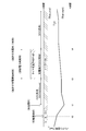
- 2 is a flowchart showing a battery charge control program executed by a controller in FIG. 3 is an operation time chart of the battery charge control program shown in FIG.
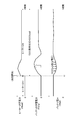
- FIG. 4 is an operation time chart showing an enlarged time axis between a battery heating start time t1 in FIG. 3 and a specified charging end time t3.
- FIG. 1 is a control system diagram of a battery charge control device according to an embodiment of the present invention.
- a main battery 1 used for running an electric vehicle such as an electric vehicle or a hybrid vehicle is used as the battery charge control device. It shall be for charging.
- the main battery 1 is a large-capacity battery that can be used to drive a motor for driving, in which a plurality of battery modules each formed by stacking a plurality of battery shells are integrated into one set.
- 2 is a heater for adjusting the temperature of the battery 1, which corresponds to the electric power load in the present invention, and this heater 2 is arranged along the stacking direction of the battery shell with respect to the battery module.
- the battery 1 is provided in the immediate vicinity of the battery module so that the battery 1 can be heated.
- reference numeral 3 denotes an electric motor used for driving the electric vehicle.
- the electric motor 3 is electrically connected to the battery 1 via the inverter 4.
- a main relay switch 5 is inserted in the electric path between the inverter 4 and the battery 1, and this main relay switch 5 is opened and closed via an unillustrated drive controller in conjunction with an unillustrated ignition switch of the electric vehicle. It is closed when the ignition switch is turned on and opened when the ignition switch is turned off.
- the main relay switch 5 While the main relay switch 5 is closed in conjunction with the ON of the ignition switch, the DC power from the battery 1 is converted from DC to AC by the inverter 4 and output to the electric motor 3 under the control of the inverter 4. The electric vehicle can be driven by driving the motor 3.
- the main relay switch 5 When the main relay switch 5 is opened in conjunction with the ignition switch being turned off, the DC power from the battery 1 cannot go to the electric motor 3, and the electric vehicle can be kept stopped by stopping the motor 3.
- a charger 7 is connected between the DC side of the inverter 4 and the main relay switch 5, and this charger 7 is not shown when connected to an external power source of a charging stand or a battery charging facility at home.
- the main relay switch 5 is closed by the charging controller, and the battery 1 can be charged by the external power source.
- the heater 2 provided along the stacking direction of the battery shell in the immediate vicinity of the battery module so that the temperature of the battery 1 can be adjusted is between the DC side of the inverter 4 and the main relay switch 5 as shown in FIG.
- the heater switch 8 is inserted into the electric path between the connection portion and the heater 2.
- the opening and closing of the heater switch 8 is controlled via a relay drive circuit 6 by a controller 9 that controls the temperature of the battery 1 and charge control.
- the controller 9 is further operated while the main relay switch 5 is opened in conjunction with the ignition switch being turned off and while the main relay switch 5 is closed in conjunction with the connection of the charger 7 to the external power source.
- the main relay switch 5 is also controlled to open and close via the relay drive circuit 6.
- the controller 9 closes the main relay switch 5 and energizes the heater 2 in synchronization with the heater switch 8 being closed.
- the main relay switch 5 is also opened in synchronization with the heater switch 8 being “open”, and the heater 2 is deenergized (OFF).
- the controller 9 opens and closes the main relay switch 5 on the condition that the heater switch 8 is in the “closed” state while the main relay switch 5 is closed in conjunction with the connection of the charger 7 to the external power supply. In this case, the battery charge control described below, which is the target of the present invention, is performed. When the heater switch 8 is “open”, the main relay switch 5 is opened and the battery is not charged.
- the controller 9 includes a battery 1 for performing ON / OFF control of the heater 2 (battery temperature adjustment ON / OFF) through the above-described opening / closing of the heater switch 8 and the main relay switch 5 and charging control of the battery 1.
- a battery 1 for performing ON / OFF control of the heater 2 (battery temperature adjustment ON / OFF) through the above-described opening / closing of the heater switch 8 and the main relay switch 5 and charging control of the battery 1.
- the charging time commander 13 can reduce the running cost by fully charging the battery 1 using inexpensive late-night power, or the battery 1 can be fully charged at the departure time so that the mileage becomes the longest. Therefore, the vehicle user instructs the battery charging time.
- the controller 9 executes a control program (not shown) based on the input information to adjust the battery temperature, and also executes the control program shown in FIG. 2 to control the charging of the battery 1 in the following manner.
- the temperature adjustment of the battery 1 that is disconnected from the electric motor 3 (inverter 4) and is not in use by turning off the ignition switch ("opening" the main relay switch 5) will be schematically described.
- Battery 1 that is not in use has zero input / output power due to freezing of the electrolyte, especially in extremely cold regions, and it becomes impossible to run. Therefore, it is necessary to operate heater 2 as appropriate to heat battery 1 and adjust the temperature. There is. For this reason, when the ignition switch is OFF, the battery temperature Tbat is the heating start temperature Tbat_start illustrated in FIG. 3 (for example, less than about ⁇ 17 ° C., or the heating end temperature Tbat_stop illustrated in FIG. 3 is also illustrated, for example ⁇ 10 ° C.). Check if this is the case.
- the controller 9 Before the instant t1 in FIG. 3 when the battery temperature Tbat falls below the warming start temperature Tbat_start (Tbat ⁇ Tbat_start), the controller 9 has a heater switch 8 and a main relay switch because there is no concern about the battery electrolyte freezing. By opening 5, the heater 2 is turned off and the battery 1 is not heated.
- the controller 9 turns on the heater 2 by closing the heater switch 8 and the main relay switch 5 to warm the battery 1 I do.
- the controller 9 checks whether or not the battery temperature Tbat becomes equal to or higher than the heating end temperature Tbat_stop every time the above-described time interval elapses. Continues to heat the battery 1 by turning on the heater 2 by “closing” the heater switch 8 and the main relay switch 5.
- the controller 9 turns off the heater 2 and ends the heating of the battery 1 by opening the heater switch 8 and the main relay switch 5.
- the battery 1 is not left as Tbat ⁇ Tbat_stop, and it is possible to prevent the electrolytic solution from freezing and being unable to run. Further, when Tbat ⁇ Tbat_stop, the heater 2 is turned off and the heating of the battery 1 is terminated. Therefore, it is possible to prevent unnecessary power consumption when the heater 2 is turned on.
- the control program in FIG. 2 connects the charger 7 to the external power source of the charging station or the battery charging facility at home as shown in FIG. 3 at the instant t0, so that the main relay switch 5 is closed and the charging is possible. It will be executed from the time.
- step S11 it is checked whether the timer charge reservation time is between the charge start time and the charge end time specified by the charge time command unit 13.
- the designated charging start time is shown as t3 after the instant t1
- the designated charging end time is shown as the instant t4.
- step S11 If it is determined in step S11 that the current time is not during the timer charging reservation time (t3 to t4), it is checked in step S12 whether or not the battery 1 is being heated depending on whether the heater switch 8 is ON. In addition, in the charger connected state as in the time t0 and after in FIG. 3, since the power from the charger 7 exists, if the heater switch 8 is ON, regardless of whether the main relay switch 5 is ON or OFF. The heater 2 can be operated, and therefore, in step S12, as described above, it can be checked whether or not the battery 1 is being heated only by whether or not the heater switch 8 is ON.
- step S12 If it is determined in step S12 that the battery 1 is being heated by turning on the heater 2, whether or not the battery holding capacity SOChold to be acquired at the start of the heating (t1 in FIG. 3) has already been acquired in step S14. Check whether or not. If the battery holding capacity SOChold has not yet been acquired, the battery storage state SOC (t1) at the start of heating (t1 in FIG. 3) is set to the battery holding capacity SOChold in step S15, and then control proceeds to step S16. If the battery holding capacity SOChold has already been acquired by executing step S15, step S15 is skipped and control proceeds to step S16.
- Step S16 corresponds to the storage state holding charge power control means in the present invention.
- the main relay switch 5 is turned on and off so that the battery storage state SOC is maintained at the battery holding capacity SOChold.
- the charging power Pchg to the battery 1 is controlled.
- SOC SOChold
- the main relay switch 5 is turned on to supply charging power from the charger 7 to the battery 1
- SOC SOChold
- the main relay switch 5 is turned off to turn off the charger 7. This can be realized by preventing charging power from being supplied to the battery 1.
- FIG. 4 shows the time axis between the heating start time t1 in FIG. 3 and the specified charging start time t3 in an enlarged manner as compared with FIG. 3, and the heater power consumption Pheat is immediately after the instant t1.
- the battery storage state SOC is suddenly increased by that amount, and temporarily deteriorates as apparent from the downward trend indicated by the solid line of the battery voltage Vbat immediately after the instant t1. If such deterioration of the battery charge state SOC is left unattended, the battery charge state SOC cannot be fully charged as intended during the timer reserved charge times t3 to t4 in FIG. 3, and the charge rate using inexpensive late-night power is reduced. There arises a problem that the running cost increases due to a decrease, or the running distance is shortened because the battery 1 is not fully charged at the start of running after the end of charging at the instant t4.
- step S16 the charging power Pchg to the battery 1 is shown in FIG. 4 immediately after the heating start t1 in FIG. 4 so that the battery storage state SOC is maintained at the battery holding capacity SOChold.
- the battery voltage Vbat can be maintained at a level equivalent to the battery holding capacity SOChold as indicated by the wavy line even immediately after the instant t1. Therefore, there is no battery charging that increases the battery storage state SOC beyond the instant t1 level other than the timer reserved charging times t3 to t4 in FIG. 3, and during the timer reserved charging times t3 to t4 in FIG.
- the battery state of charge SOC can be fully charged as intended, and the running rate can be suppressed by maximizing the charging rate using inexpensive late-night power, and running after the instant t4 charging ends Sometimes the battery 1 can be fully charged and the mileage can be extended to the maximum.
- step S17 the charging power Pchg to the battery 1 is controlled by turning on and off the main relay switch 5 so that the battery storage state SOC becomes the full charge state SOCfull.
- SOC ⁇ SOCfull the charging power is supplied from the charger 7 to the battery 1 when the main relay switch 5 is turned ON.
- the designation intention of the timer charge reservation time can be reliably achieved, All the power consumed for full charge is covered by inexpensive late-night power, and running costs can be suppressed.
- the timer charge reservation time (t3 to t4) is now Otherwise, to control the charging power Pchg to the battery 1 so that the battery storage state SOC is maintained at the battery holding capacity SOChold which is the battery storage state SOC (t1) at the start of heating t1, as shown in FIG.
- the heater power consumption Pheat rapidly increases immediately after the start of heating t1, and the battery storage state SOC tends to temporarily deteriorate as clearly shown from the decreasing trend indicated by the solid line of the battery voltage Vbat immediately after the instant t1.
- the battery voltage Vbat immediately after the instant t1 can be maintained at a level equivalent to the battery holding capacity SOChold as indicated by a broken line.
- the battery charge state SOC can be fully charged as intended, and the running rate can be suppressed by maximizing the charging rate using inexpensive late-night power, and running after the instant t4 charging ends
- the battery 1 can be surely fully charged at the start, and the mileage can be extended to the maximum.
- the charging power Pchg to the battery 1 is controlled so that the battery charge state SOC is set to the full charge state SOCfull. All the electric power to be used is covered by cheap late-night electric power, and the running cost can be suppressed.
Landscapes
- Engineering & Computer Science (AREA)
- Manufacturing & Machinery (AREA)
- Chemical & Material Sciences (AREA)
- Chemical Kinetics & Catalysis (AREA)
- Electrochemistry (AREA)
- General Chemical & Material Sciences (AREA)
- Power Engineering (AREA)
- Mechanical Engineering (AREA)
- Transportation (AREA)
- Life Sciences & Earth Sciences (AREA)
- Sustainable Development (AREA)
- Sustainable Energy (AREA)
- Electromagnetism (AREA)
- Physics & Mathematics (AREA)
- Automation & Control Theory (AREA)
- Secondary Cells (AREA)
- Charge And Discharge Circuits For Batteries Or The Like (AREA)
- Electric Propulsion And Braking For Vehicles (AREA)
Abstract
Description
バッテリは温度低下すると、蓄電状態SOCが低下するわけではないが、内部抵抗の増大によりバッテリに対する入出力可能電力が低下し、バッテリ電解液が凍結すると、バッテリの入出力可能電力が遂には0になって、バッテリを走行エネルギー源とする電動車両の場合は走行不能に陥る。
つまり、バッテリ温度が設定温度未満に低下した時、ヒーターを作動させてバッテリを加温するが、この際さらに、バッテリ蓄電状態が所定値未満であれば、バッテリへの充電をも併せて行い、充電により発生する熱によってもバッテリを加温しようとするものである。
つまり特許文献1の装置では前記した通り、バッテリ温度が設定温度未満に低下し、且つ、バッテリ蓄電状態が所定値未満であるとき、バッテリ蓄電状態が増大するようバッテリへの充電を行うものであるため、当該バッテリ蓄電状態を増大させるためのバッテリ充電が上記の充電指定時刻以外に行われてしまう。
先ず本発明の前提となるバッテリ充電制御装置を説明するに、これは、充電時刻を指定して充電可能なバッテリと、該バッテリの充電電力系に接続され、所定条件の成立時に該充電電力系を経由した電力により作動される電力負荷とを具えたものである。
この蓄電状態保持用充電電力制御手段は、上記電力負荷が作動されている間、上記指定した充電時刻中でない場合は、バッテリへの充電電力を、満充電よりも小さな所定のバッテリ蓄電状態に保持するようにしたものである。
図1は、本発明の一実施例になるバッテリ充電制御装置の制御システム図で、本実施例では、このバッテリ充電制御装置を、電気自動車やハイブリッド車両など電動車両の走行に用いるメインバッテリ1を充電するためのものとする。
またメインバッテリ1は、複数個の電池シェルを積層してユニット化した電池モジュールを多数個、1セットにして一体化した、走行用モータの駆動に供し得る大容量のバッテリとする。
そして、インバータ4およびバッテリ1間の電路中にメインリレースイッチ5を挿置し、このメインリレースイッチ5は、電動車両の図示せざるイグニッションスイッチに連動して、同じく図示せざる駆動コントローラを介し開閉され、イグニッションスイッチのON時に閉じ、イグニッションスイッチのOFF時に開くものとする。
イグニッションスイッチのOFFに連動してメインリレースイッチ5が開いている場合、バッテリ1からの直流電力は電動モータ3に向かい得ず、該モータ3の停止により電動車両を停車状態に保つことができる。
上記した通りバッテリ1の温度調節を行い得るよう、電池モジュールの直近において電池シェルの積層方向に沿うよう設けたヒーター2は、図1に示すごとくインバータ4の直流側とメインリレースイッチ5との間に電気接続し、この接続部とヒーター2との間の電路中にヒータースイッチ8を挿置する。
このコントローラ9は更に、メインリレースイッチ5がイグニッションスイッチのOFFに連動して開かれている間、および、メインリレースイッチ5が充電器7の外部電源への接続に連動して閉じられている間、当該メインリレースイッチ5をも、リレー駆動回路6を介して開閉制御するものとする。
不使用状態のバッテリ1は、特に厳寒地において電解液の凍結により入出力可能電力が0となり、走行不能になることから、適宜ヒーター2を作動させてバッテリ1を加温し、温度調節する必要がある。
このため、イグニッションスイッチOFF中は、バッテリ温度Tbatが図3に例示する加温開始温度Tbat_start(例えば-17℃程未満か、また同じく図3に例示する加温終了温度Tbat_stop(例えば-10℃)以上か否かをチェックする。
また、Tbat≧Tbat_stopになるとき、ヒーター2をOFFにしてバッテリ1の加温を終了するため、不要なヒーター2のONで電力が無駄に消費されるのを防止することができる。
図2の制御プログラムは、図3の瞬時t0におけるごとく充電器7を、充電スタンドや自宅に在るバッテリ充電設備の外部電源に接続したことで、メインリレースイッチ5が閉じられ、充電可能状態になった時から実行される。
図3では、指定された充電開始時刻を瞬時t1の後のt3とし、また指定された充電終了時刻を瞬時t4として示した。
なお、図3の瞬時t0以降におけるように充電器接続状態では、充電器7からの電力が存在しているため、ヒータースイッチ8がONであれば、メインリレースイッチ5のON,OFFに関係なくヒーター2を作動させることができ、従ってステップS12では上記の通り、ヒータースイッチ8がON中か否かのみにより、バッテリ1が加温中か否かをチェックすることができる。
未だバッテリ保持容量SOCholdを取得済みでなければ、ステップS15において加温開始時(図3ではt1)のバッテリ蓄電状態SOC(t1)をバッテリ保持容量SOCholdに設定した後、制御をステップS16に進め、既にステップS15の実行によりバッテリ保持容量SOCholdを取得済みであれば、このステップS15をスキップして、制御をステップS16に進める。
この制御は、SOC<SOCholdであれば、メインリレースイッチ5のONにより充電器7からバッテリ1へ充電電力を供給し、またSOC=SOCholdになったら、メインリレースイッチ5のOFFにより充電器7からバッテリ1へ充電電力が供給されないようにすることで、実現可能である。
かかるバッテリ蓄電状態SOCの悪化を放置しておくと、図3のタイマ予約充電時刻t3~t4中にバッテリ蓄電状態SOCを狙い通り満充電状態にし得なくなり、安価な深夜電力を用いた充電割合が低下してランニングコストが高くなったり、瞬時t4の充電終了後における走行開始時にバッテリ1が満充電状態でなくて、走行距離が短くなるという問題を生ずる。
このため、図3のタイマ予約充電時刻t3~t4以外にバッテリ蓄電状態SOCを瞬時t1のレベルよりも増大させるバッテリ充電が行われることがなくて、図3のタイマ予約充電時刻t3~t4中にバッテリ蓄電状態SOCを狙い通り満充電状態にすることができ、安価な深夜電力を用いた充電割合を最大限に高めてランニングコストを抑制することができ、また瞬時t4の充電終了後における走行開始時に確実にバッテリ1を満充電状態にすることができ、走行距離を最大限が延長することができる。
このステップS17においては、バッテリ蓄電状態SOCが満充電状態SOCfullとなるようメインリレースイッチ5のON,OFFによりバッテリ1への充電電力Pchgを制御する。
この制御は、SOC<SOCfullであれば、メインリレースイッチ5のONにより充電器7からバッテリ1へ充電電力を供給し、またSOC=SOCfullになったら、メインリレースイッチ5のOFFにより充電器7からバッテリ1へ充電電力が供給されないようにすることで、実現可能である。
瞬時t1以降のヒーター2(電力負荷)の作動によるバッテリ1の加温中、今がタイマ充電予約時刻(t3~t4)であるか否かに応じ、今がタイマ充電予約時刻(t3~t4)でなければ、バッテリ蓄電状態SOCが、加温開始時t1のバッテリ蓄電状態SOC(t1)であるバッテリ保持容量SOCholdに保たれるようバッテリ1への充電電力Pchgを制御するため、図4に示すごとく加温開始時t1の直後にヒーター消費電力Pheatが急増し、その分だけバッテリ蓄電状態SOCが、瞬時t1の直後におけるバッテリ電圧Vbatの実線で示す低下傾向から明らかなごとく一時的に悪化する傾向にあっても、瞬時t1の直後におけるバッテリ電圧Vbatを波線で示すごとく、バッテリ保持容量SOChold相当のレベルに保つことができる。
Claims (3)
- 充電時刻を指定して充電可能なバッテリと、該バッテリの充電電力系に接続され、所定条件の成立時に該充電電力系を経由した電力により作動される電力負荷とを具えたバッテリ充電制御装置において、
前記電力負荷が作動されている間、前記指定した充電時刻中でない場合は、前記バッテリへの充電電力を、満充電よりも小さな所定のバッテリ蓄電状態に保持する蓄電状態保持用充電電力制御手段を設けたバッテリ充電制御装置。 - 請求項1に記載のバッテリ充電制御装置において、
前記満充電よりも小さな所定のバッテリ蓄電状態は、前記電力負荷が作動を開始した時のバッテリ蓄電状態にバッテリを保つのに必要な充電電力であるバッテリ充電制御装置。 - 請求項1または2に記載のバッテリ充電制御装置において、
前記電力負荷が、バッテリを所定温度未満になるときに加温して温度調節するヒーターであるバッテリ充電制御装置。
Priority Applications (4)
| Application Number | Priority Date | Filing Date | Title |
|---|---|---|---|
| KR1020137023910A KR101571943B1 (ko) | 2011-03-11 | 2012-03-01 | 배터리 충전 제어 장치 |
| EP12757908.4A EP2685599B1 (en) | 2011-03-11 | 2012-03-01 | Battery charging control device |
| CN201280012912.XA CN103430423B (zh) | 2011-03-11 | 2012-03-01 | 电池充电控制装置 |
| US14/003,951 US20130342015A1 (en) | 2011-03-11 | 2012-03-01 | Battery charging control device |
Applications Claiming Priority (2)
| Application Number | Priority Date | Filing Date | Title |
|---|---|---|---|
| JP2011054094A JP5736860B2 (ja) | 2011-03-11 | 2011-03-11 | バッテリ充電制御装置 |
| JP2011-054094 | 2011-03-11 |
Publications (1)
| Publication Number | Publication Date |
|---|---|
| WO2012124490A1 true WO2012124490A1 (ja) | 2012-09-20 |
Family
ID=46830565
Family Applications (1)
| Application Number | Title | Priority Date | Filing Date |
|---|---|---|---|
| PCT/JP2012/055209 Ceased WO2012124490A1 (ja) | 2011-03-11 | 2012-03-01 | バッテリ充電制御装置 |
Country Status (6)
| Country | Link |
|---|---|
| US (1) | US20130342015A1 (ja) |
| EP (1) | EP2685599B1 (ja) |
| JP (1) | JP5736860B2 (ja) |
| KR (1) | KR101571943B1 (ja) |
| CN (1) | CN103430423B (ja) |
| WO (1) | WO2012124490A1 (ja) |
Cited By (2)
| Publication number | Priority date | Publication date | Assignee | Title |
|---|---|---|---|---|
| WO2013174273A1 (en) * | 2012-05-22 | 2013-11-28 | Shenzhen Byd Auto R&D Company Limited | Power system of electric vehicle, electric vehicle comprising the same and method for heating battery group of electric vehicle |
| US10664365B2 (en) | 2017-08-21 | 2020-05-26 | Google Llc | System and method for monitoring and controlling a back-up power supply using temperature controlled batteries |
Families Citing this family (16)
| Publication number | Priority date | Publication date | Assignee | Title |
|---|---|---|---|---|
| JP6483441B2 (ja) * | 2012-09-19 | 2019-03-13 | 日産自動車株式会社 | 車両制御システム、車両情報提供装置、及び、車両情報提供方法 |
| JP6050198B2 (ja) * | 2013-08-26 | 2016-12-21 | トヨタ自動車株式会社 | 蓄電システム |
| TWI681691B (zh) * | 2014-04-30 | 2020-01-01 | 瑞士商菲利浦莫里斯製品股份有限公司 | 電熱式氣溶膠產生系統、裝置及其控制方法 |
| JP6331697B2 (ja) * | 2014-05-28 | 2018-05-30 | トヨタ自動車株式会社 | 蓄電システム |
| JP2016208639A (ja) * | 2015-04-21 | 2016-12-08 | トヨタ自動車株式会社 | 車両 |
| SE1551609A1 (en) * | 2015-12-08 | 2017-03-28 | Scania Cv Ab | Method and control system for charging an accessory battery and a hybrid energy storage of a plug-in hybrid vehicle |
| US10108245B2 (en) | 2016-04-11 | 2018-10-23 | Microsoft Technology Licensing, Llc | Interaction based charging control |
| JP6520848B2 (ja) | 2016-07-04 | 2019-05-29 | トヨタ自動車株式会社 | 電動車両のバッテリ充電システム |
| JP6493344B2 (ja) * | 2016-09-12 | 2019-04-03 | トヨタ自動車株式会社 | 自動車 |
| KR102768964B1 (ko) | 2016-12-19 | 2025-02-18 | 현대자동차주식회사 | 전기 자동차, 그를 포함하는 시스템 및 전기 자동차의 배터리 충전 방법 |
| US11215156B2 (en) | 2017-03-03 | 2022-01-04 | Gentherm Incorporated | Dual voltage battery system for a vehicle |
| KR102212445B1 (ko) * | 2019-02-01 | 2021-02-04 | 주식회사 현대케피코 | 차량 배터리의 예약 충전을 위한 ig 릴레이 제어 장치 및 방법 |
| TWI726373B (zh) * | 2019-08-01 | 2021-05-01 | 拓連科技股份有限公司 | 充電管理伺服器及充電管理方法 |
| CN112339601A (zh) * | 2020-11-11 | 2021-02-09 | 上海电享信息科技有限公司 | 一种电动汽车智能充电方法和系统 |
| CN115042656A (zh) * | 2022-07-07 | 2022-09-13 | 浙江吉利控股集团有限公司 | 电动车充电控制方法、装置、设备及存储介质 |
| KR102684686B1 (ko) * | 2023-02-21 | 2024-07-12 | 이엔테크놀로지 주식회사 | 에너지 저장 장치를 구비한 충전기 및 그의 동작 방법 |
Citations (2)
| Publication number | Priority date | Publication date | Assignee | Title |
|---|---|---|---|---|
| JPH08214411A (ja) * | 1995-02-06 | 1996-08-20 | Honda Motor Co Ltd | 電気自動車用蓄電池充電制御装置 |
| JP2000040536A (ja) | 1998-07-23 | 2000-02-08 | Toyota Motor Corp | バッテリ暖機装置 |
Family Cites Families (16)
| Publication number | Priority date | Publication date | Assignee | Title |
|---|---|---|---|---|
| US5710507A (en) * | 1996-04-26 | 1998-01-20 | Lucent Technologies Inc. | Temperature-controlled battery reserve system and method of operation thereof |
| JP2002233074A (ja) | 2001-02-05 | 2002-08-16 | Nec Corp | バッテリ充放電システム |
| JP4281725B2 (ja) * | 2005-09-01 | 2009-06-17 | トヨタ自動車株式会社 | ハイブリッド自動車 |
| JP4854557B2 (ja) * | 2007-03-27 | 2012-01-18 | 株式会社エクォス・リサーチ | 電動駆動制御装置 |
| US7849944B2 (en) * | 2007-06-12 | 2010-12-14 | Ut-Battelle, Llc | Self-learning control system for plug-in hybrid vehicles |
| US9457791B2 (en) * | 2009-01-06 | 2016-10-04 | GM Global Technology Operations LLC | Charging cable with controller |
| US8118237B2 (en) * | 2009-02-16 | 2012-02-21 | General Electric Company | System and method for vehicle temperature control |
| US20100292855A1 (en) * | 2009-05-14 | 2010-11-18 | Michael Kintner-Meyer | Battery Charging Control Methods, Electrical Vehicle Charging Methods, Battery Charging Control Apparatus, and Electrical Vehicles |
| JP2010285110A (ja) * | 2009-06-12 | 2010-12-24 | Toyota Motor Corp | 車両およびその制御方法 |
| US8890473B2 (en) * | 2009-07-28 | 2014-11-18 | Bosch Automotive Service Solutions Llc | Sequential charging of multiple electric vehicles |
| US9431688B2 (en) * | 2010-05-21 | 2016-08-30 | GM Global Technology Operations LLC | Method for heating a high voltage vehicle battery |
| KR101185735B1 (ko) * | 2010-07-16 | 2012-09-26 | 엘에스산전 주식회사 | 전기 자동차용 배터리 디스커넥트 유닛 |
| JP5699702B2 (ja) * | 2011-03-11 | 2015-04-15 | 日産自動車株式会社 | 車両の充電制御装置 |
| JP5668542B2 (ja) * | 2011-03-11 | 2015-02-12 | 日産自動車株式会社 | 車両の充電制御装置 |
| JP5732930B2 (ja) * | 2011-03-11 | 2015-06-10 | 日産自動車株式会社 | バッテリ充電制御装置 |
| JP5668541B2 (ja) * | 2011-03-11 | 2015-02-12 | 日産自動車株式会社 | 車両の充電制御装置 |
-
2011
- 2011-03-11 JP JP2011054094A patent/JP5736860B2/ja active Active
-
2012
- 2012-03-01 WO PCT/JP2012/055209 patent/WO2012124490A1/ja not_active Ceased
- 2012-03-01 US US14/003,951 patent/US20130342015A1/en not_active Abandoned
- 2012-03-01 CN CN201280012912.XA patent/CN103430423B/zh active Active
- 2012-03-01 EP EP12757908.4A patent/EP2685599B1/en active Active
- 2012-03-01 KR KR1020137023910A patent/KR101571943B1/ko active Active
Patent Citations (2)
| Publication number | Priority date | Publication date | Assignee | Title |
|---|---|---|---|---|
| JPH08214411A (ja) * | 1995-02-06 | 1996-08-20 | Honda Motor Co Ltd | 電気自動車用蓄電池充電制御装置 |
| JP2000040536A (ja) | 1998-07-23 | 2000-02-08 | Toyota Motor Corp | バッテリ暖機装置 |
Non-Patent Citations (1)
| Title |
|---|
| See also references of EP2685599A4 |
Cited By (3)
| Publication number | Priority date | Publication date | Assignee | Title |
|---|---|---|---|---|
| WO2013174273A1 (en) * | 2012-05-22 | 2013-11-28 | Shenzhen Byd Auto R&D Company Limited | Power system of electric vehicle, electric vehicle comprising the same and method for heating battery group of electric vehicle |
| US10664365B2 (en) | 2017-08-21 | 2020-05-26 | Google Llc | System and method for monitoring and controlling a back-up power supply using temperature controlled batteries |
| TWI702770B (zh) * | 2017-08-21 | 2020-08-21 | 美商谷歌有限責任公司 | 用於監測及控制使用溫度控制電池之備用電源供應器之系統及方法 |
Also Published As
| Publication number | Publication date |
|---|---|
| JP5736860B2 (ja) | 2015-06-17 |
| EP2685599A4 (en) | 2014-08-27 |
| CN103430423A (zh) | 2013-12-04 |
| US20130342015A1 (en) | 2013-12-26 |
| KR101571943B1 (ko) | 2015-11-25 |
| CN103430423B (zh) | 2016-05-25 |
| KR20130135911A (ko) | 2013-12-11 |
| EP2685599B1 (en) | 2017-09-06 |
| JP2012191785A (ja) | 2012-10-04 |
| EP2685599A1 (en) | 2014-01-15 |
Similar Documents
| Publication | Publication Date | Title |
|---|---|---|
| JP5736860B2 (ja) | バッテリ充電制御装置 | |
| JP5732930B2 (ja) | バッテリ充電制御装置 | |
| JP5760531B2 (ja) | バッテリ温度制御装置 | |
| CN108028442B (zh) | 蓄电池的加温控制装置 | |
| KR101609034B1 (ko) | 배터리 온도 제어 장치 | |
| JP6229539B2 (ja) | 車両のバッテリ制御装置 | |
| WO2017056162A1 (ja) | 電力消費制御装置 | |
| JP2016152067A (ja) | 蓄電システム | |
| WO2013129217A1 (ja) | 電動車両 | |
| JP2014075297A (ja) | 蓄電システム | |
| JP2016111721A (ja) | 車両の充電制御装置 | |
| CN113997829B (zh) | 一种保障电动汽车电池充电加热稳定不停机的控制方法 | |
| JP6402687B2 (ja) | 車両電池システム | |
| JP7439775B2 (ja) | 電動車両の電源システム | |
| JP2022149837A (ja) | 車両の暖房装置 |
Legal Events
| Date | Code | Title | Description |
|---|---|---|---|
| 121 | Ep: the epo has been informed by wipo that ep was designated in this application |
Ref document number: 12757908 Country of ref document: EP Kind code of ref document: A1 |
|
| REEP | Request for entry into the european phase |
Ref document number: 2012757908 Country of ref document: EP |
|
| WWE | Wipo information: entry into national phase |
Ref document number: 14003951 Country of ref document: US |
|
| ENP | Entry into the national phase |
Ref document number: 20137023910 Country of ref document: KR Kind code of ref document: A |
|
| NENP | Non-entry into the national phase |
Ref country code: DE |