WO2012124767A1 - ホイールローダ - Google Patents
ホイールローダ Download PDFInfo
- Publication number
- WO2012124767A1 WO2012124767A1 PCT/JP2012/056714 JP2012056714W WO2012124767A1 WO 2012124767 A1 WO2012124767 A1 WO 2012124767A1 JP 2012056714 W JP2012056714 W JP 2012056714W WO 2012124767 A1 WO2012124767 A1 WO 2012124767A1
- Authority
- WO
- WIPO (PCT)
- Prior art keywords
- arm
- bucket
- mode
- speed
- operation lever
- Prior art date
- Legal status (The legal status is an assumption and is not a legal conclusion. Google has not performed a legal analysis and makes no representation as to the accuracy of the status listed.)
- Ceased
Links
Images



Classifications
-
- E—FIXED CONSTRUCTIONS
- E02—HYDRAULIC ENGINEERING; FOUNDATIONS; SOIL SHIFTING
- E02F—DREDGING; SOIL-SHIFTING
- E02F9/00—Component parts of dredgers or soil-shifting machines, not restricted to one of the kinds covered by groups E02F3/00 - E02F7/00
- E02F9/20—Drives; Control devices
- E02F9/2004—Control mechanisms, e.g. control levers
- E02F9/2012—Setting the functions of the control levers, e.g. changing assigned functions among operations levers, setting functions dependent on the operator or seat orientation
-
- E—FIXED CONSTRUCTIONS
- E02—HYDRAULIC ENGINEERING; FOUNDATIONS; SOIL SHIFTING
- E02F—DREDGING; SOIL-SHIFTING
- E02F9/00—Component parts of dredgers or soil-shifting machines, not restricted to one of the kinds covered by groups E02F3/00 - E02F7/00
- E02F9/20—Drives; Control devices
-
- E—FIXED CONSTRUCTIONS
- E02—HYDRAULIC ENGINEERING; FOUNDATIONS; SOIL SHIFTING
- E02F—DREDGING; SOIL-SHIFTING
- E02F3/00—Dredgers; Soil-shifting machines
- E02F3/04—Dredgers; Soil-shifting machines mechanically-driven
- E02F3/28—Dredgers; Soil-shifting machines mechanically-driven with digging tools mounted on a dipper- or bucket-arm, i.e. there is either one arm or a pair of arms, e.g. dippers, buckets
- E02F3/283—Dredgers; Soil-shifting machines mechanically-driven with digging tools mounted on a dipper- or bucket-arm, i.e. there is either one arm or a pair of arms, e.g. dippers, buckets with a single arm pivoted directly on the chassis
-
- E—FIXED CONSTRUCTIONS
- E02—HYDRAULIC ENGINEERING; FOUNDATIONS; SOIL SHIFTING
- E02F—DREDGING; SOIL-SHIFTING
- E02F3/00—Dredgers; Soil-shifting machines
- E02F3/04—Dredgers; Soil-shifting machines mechanically-driven
- E02F3/28—Dredgers; Soil-shifting machines mechanically-driven with digging tools mounted on a dipper- or bucket-arm, i.e. there is either one arm or a pair of arms, e.g. dippers, buckets
- E02F3/34—Dredgers; Soil-shifting machines mechanically-driven with digging tools mounted on a dipper- or bucket-arm, i.e. there is either one arm or a pair of arms, e.g. dippers, buckets with bucket-arms, i.e. a pair of arms, e.g. manufacturing processes, form, geometry, material of bucket-arms directly pivoted on the frames of tractors or self-propelled machines
-
- E—FIXED CONSTRUCTIONS
- E02—HYDRAULIC ENGINEERING; FOUNDATIONS; SOIL SHIFTING
- E02F—DREDGING; SOIL-SHIFTING
- E02F3/00—Dredgers; Soil-shifting machines
- E02F3/04—Dredgers; Soil-shifting machines mechanically-driven
- E02F3/28—Dredgers; Soil-shifting machines mechanically-driven with digging tools mounted on a dipper- or bucket-arm, i.e. there is either one arm or a pair of arms, e.g. dippers, buckets
- E02F3/36—Component parts
- E02F3/42—Drives for dippers, buckets, dipper-arms or bucket-arms
- E02F3/43—Control of dipper or bucket position; Control of sequence of drive operations
- E02F3/431—Control of dipper or bucket position; Control of sequence of drive operations for bucket-arms, front-end loaders, dumpers or the like
-
- E—FIXED CONSTRUCTIONS
- E02—HYDRAULIC ENGINEERING; FOUNDATIONS; SOIL SHIFTING
- E02F—DREDGING; SOIL-SHIFTING
- E02F9/00—Component parts of dredgers or soil-shifting machines, not restricted to one of the kinds covered by groups E02F3/00 - E02F7/00
- E02F9/02—Travelling-gear, e.g. associated with slewing gears
-
- E—FIXED CONSTRUCTIONS
- E02—HYDRAULIC ENGINEERING; FOUNDATIONS; SOIL SHIFTING
- E02F—DREDGING; SOIL-SHIFTING
- E02F9/00—Component parts of dredgers or soil-shifting machines, not restricted to one of the kinds covered by groups E02F3/00 - E02F7/00
- E02F9/20—Drives; Control devices
- E02F9/2058—Electric or electro-mechanical or mechanical control devices of vehicle sub-units
- E02F9/2062—Control of propulsion units
- E02F9/2066—Control of propulsion units of the type combustion engines
-
- E—FIXED CONSTRUCTIONS
- E02—HYDRAULIC ENGINEERING; FOUNDATIONS; SOIL SHIFTING
- E02F—DREDGING; SOIL-SHIFTING
- E02F9/00—Component parts of dredgers or soil-shifting machines, not restricted to one of the kinds covered by groups E02F3/00 - E02F7/00
- E02F9/20—Drives; Control devices
- E02F9/2058—Electric or electro-mechanical or mechanical control devices of vehicle sub-units
- E02F9/2079—Control of mechanical transmission
-
- E—FIXED CONSTRUCTIONS
- E02—HYDRAULIC ENGINEERING; FOUNDATIONS; SOIL SHIFTING
- E02F—DREDGING; SOIL-SHIFTING
- E02F9/00—Component parts of dredgers or soil-shifting machines, not restricted to one of the kinds covered by groups E02F3/00 - E02F7/00
- E02F9/20—Drives; Control devices
- E02F9/22—Hydraulic or pneumatic drives
- E02F9/2253—Controlling the travelling speed of vehicles, e.g. adjusting travelling speed according to implement loads, control of hydrostatic transmission
-
- G—PHYSICS
- G05—CONTROLLING; REGULATING
- G05G—CONTROL DEVICES OR SYSTEMS INSOFAR AS CHARACTERISED BY MECHANICAL FEATURES ONLY
- G05G9/00—Manually-actuated control mechanisms provided with one single controlling member co-operating with two or more controlled members, e.g. selectively, simultaneously
- G05G9/02—Manually-actuated control mechanisms provided with one single controlling member co-operating with two or more controlled members, e.g. selectively, simultaneously the controlling member being movable in different independent ways, movement in each individual way actuating one controlled member only
- G05G9/04—Manually-actuated control mechanisms provided with one single controlling member co-operating with two or more controlled members, e.g. selectively, simultaneously the controlling member being movable in different independent ways, movement in each individual way actuating one controlled member only in which movement in two or more ways can occur simultaneously
- G05G9/047—Manually-actuated control mechanisms provided with one single controlling member co-operating with two or more controlled members, e.g. selectively, simultaneously the controlling member being movable in different independent ways, movement in each individual way actuating one controlled member only in which movement in two or more ways can occur simultaneously the controlling member being movable by hand about orthogonal axes, e.g. joysticks
Definitions
- the present invention relates to a wheel loader that scoops and transports an object to be excavated.
- a wheel loader working machine generally has an arm cylinder for raising and lowering an arm and a bucket cylinder for dumping or crowding a bucket.
- an operation device for instructing the operation of these arm cylinder and bucket cylinder an arm
- an arm For example, there are two operation levers for operation and bucket operation (hereinafter referred to as “arm operation lever” and “bucket operation lever”, respectively) in the right hand of the driver's seat (see Patent Document 1, etc.).
- a kick-down switch for quickly shifting down is provided at the upper part of the arm operation lever to temporarily release the restriction on the maximum engine speed and increase the maximum driving force (switching the driving mode).
- a mode change switch is provided at the upper part of the bucket operation lever. According to this example, when the operation of (A) is shifted to the operation of (B), the kickdown switch is operated to drop to the low speed stage to ensure the required driving force, and during the operation of (C). If the mode switch is operated according to the situation, a greater driving force can be generated.
- the arm operation lever is operated during the operation of (B), and the bucket is mainly operated during the operation of (C).
- Each operation lever is operated.
- the operation performed during the operation of (C) is to instruct the bucket cloud and the aircraft to advance in advance while raising the arm.
- the maximum travel driving force is not necessarily large. For example, a large driving force may be required for pushing a bucket into the excavated object, but if the vehicle is driven with an excessively large driving force when the traveling load due to the excavated object is high, the road surface is caused by wheel slip. If you become drowned, it can leave an effect on your work.
- the present invention has been made in view of such circumstances from the viewpoint of user-friendliness and has been made in consideration of the actual state of the operation mode of the operator, and an object thereof is to provide a wheel loader that can further improve the operability.
- the present invention includes a vehicle body having wheels, a work machine attached to a front portion of the vehicle body, and a work machine operation device that instructs the operation of the work machine,
- the work implement operating device performs an operation related to the traction force provided on the operation lever operation instruction lever provided on the side of the driver's seat and on the upper surface of the grip of the operation lever and the side surface on the driver's seat side.
- the work machine includes an arm and a bucket, and an arm cylinder and a bucket cylinder that drive the arm and the bucket, and the work machine operating device is configured to be the operation lever.
- the two switches provided on the upper surface and the side surface on the driver's seat side, the two kick-down switches for forcibly shifting down the speed stage, and provided on the side surface on the driver's seat side of the grip of the bucket operation lever
- a mode selector switch for switching between a plurality of driving modes having different upper limit values of the maximum engine speed Characterized in that it comprises.
- the mode changeover switch is provided on the upper surface of the grip instead of or in addition to the driver seat side surface of the grip of the bucket operation lever. It is provided.
- the mode change switch is a push button, and indicates a single changeover of a plurality of travel modes having different upper limits of the engine maximum rotation speed. .
- a detent mechanism for maintaining the posture of the arm operation lever at a position for instructing an arm raising operation is provided.
- the present invention it is possible to ensure better operability by flexibly arranging the kick down switch and the mode change switch according to the actual situation of the operation mode of the operator.
- FIG. 6 is a travel performance diagram (torque diagram) showing a relationship between engine rotation speed and torque when the accelerator pedal is fully depressed in the wheel loader according to the embodiment of the present invention. It is a figure which shows the relationship between the vehicle speed and driving
- FIG. 1 is a side view of a wheel loader according to an embodiment of the present invention.
- the wheel loader 100 shown in FIG. 1 includes a vehicle body 110 and a work machine 120 attached to the front part of the vehicle body 101.
- the vehicle body 110 includes a front vehicle body 111 and a rear vehicle body 112.
- the front vehicle body 111 and the rear vehicle body 112 include a front wheel (tire) 113 and a rear wheel (tire) 114, respectively, and are connected to each other via a center pin 115 extending in the vertical direction.
- a steering cylinder is connected to the front vehicle body 111 and the rear vehicle body 112, and the front vehicle body 111 bends left and right with respect to the rear vehicle body 112 as the steering cylinder extends and contracts.
- a driver's cab 116 is mounted at the front, and an engine compartment 117 is mounted at the rear.
- the engine chamber 117 houses an engine 131 as a prime mover to be described later, a hydraulic pump 134 driven by the engine 131, a control valve 135 for controlling the direction and flow rate of the pressure oil discharged from the hydraulic pump 134, and the like. Yes.
- the work machine 120 includes an arm 121 and a bucket 122, and an arm cylinder 123 and a bucket cylinder 124 that drive the arm 121 and the bucket 122.
- the arm 121 rotates in the vertical direction (up and down movement) as the arm cylinder 123 extends and retracts
- the bucket 122 rotates in the vertical direction (dump operation or cloud operation) as the bucket cylinder 124 extends and retracts.
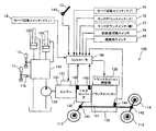
- FIG. 2 is a block diagram showing a schematic configuration of the drive system of the wheel loader 100. As shown in FIG.
- the drive system 130 of the wheel loader 100 includes an engine 131, a torque converter 132, a transmission 133, a hydraulic pump 134, a control valve 135, a controller 136, an engine control unit 137, a transmission control unit 138, and the like. ing.
- the hydraulic pump 134 is of a variable capacity type and is driven by the engine 131 to discharge the pressure oil.
- the oil discharged from the hydraulic pump 134 is supplied to working actuators such as the arm cylinder 123 and the bucket cylinder 124 by controlling the direction and flow rate via the control valve 135, and the working actuators are driven.
- the control valve 135 is operated by an arm operation lever 11 and a bucket operation lever 12 (described later), and pressure oil flows to the arm cylinder 123 and the bucket cylinder 124 in response to operation signals from the arm operation lever 11 and the bucket operation lever 12, respectively.
- the pump capacity of the hydraulic pump 134 is changed by a regulator (not shown). The regulator changes the pump capacity according to the pump discharge pressure, and performs constant torque control so that, for example, the working torque is constant.
- a fixed displacement pump such as a gear pump may be used as the hydraulic pump 134.
- the controller 136 includes an arithmetic processing unit having a CPU, ROM, RAM, and other peripheral circuits.
- the controller 136 includes an accelerator operation amount detector 143 that detects the operation amount of the accelerator pedal 13, a vehicle speed detector 144 that detects the rotation speed of the output shaft (or propeller shaft 141) of the transmission 133 as a vehicle speed, and an input of the torque converter 132.
- P mode Packhasized power mode
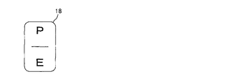
- main switch 18 for selecting one of the travel modes of “E mode” and the sub mode changeover for selecting either the P mode or the E mode of travel mode.
- Signals from the switch 19 hereinafter referred to as “sub switch 19”) are input.
- the kick down switches 16 and 17 and the sub switch 19 are all push button type switches. At this time, the kick-down switches 16 and 17 and the sub switch 19 do not output an operation signal when they are pressed slightly when the operator's fingers or palms are covered over them. In order to avoid operation that is not performed), an operation signal is not output unless a certain stroke is ensured and a required stroke is pressed.
- the torque converter 132 has a function of increasing the output torque with respect to the input torque, that is, a function of setting the torque ratio to 1 or more.
- the torque ratio decreases as the torque converter speed ratio e (output rotational speed Nt / input rotational speed Ni), which is the ratio of the rotational speeds of the input shaft and the output shaft of the torque converter 132, increases.
- the torque converter speed ratio e output rotational speed Nt / input rotational speed Ni
- the torque converter speed ratio e decreases.
- the vehicle can be driven with a larger driving force (traction force). That is, when the vehicle speed is low, the driving force is large (low speed and high torque), and when the vehicle speed is high, the driving force is low (high speed and low torque).
- the transmission 133 is an automatic transmission having a clutch and a solenoid valve corresponding to each speed stage of 1st to 4th speeds. These solenoid valves are driven by a control signal output from the controller 136 to the transmission control unit 138, and pressure oil is applied to the corresponding clutch to switch the clutch.
- the controller 136 stores in advance a torque converter speed ratio e1 as a reference for upshifting and a torque converter speed ratio e2 as a reference for downshifting.
- the controller 136 calculates the torque converter speed ratio e based on the signals from the rotation speed detectors 145 and 146, and when the calculated speed ratio e becomes larger than the reference speed ratio e1, the controller 136 generates a shift-up signal. When it becomes smaller than e2, a downshift signal is output to transmission control section 138, respectively.
- the speed stage of the transmission 133 is automatically changed between the first speed and the fourth speed in accordance with the torque converter speed ratio e.
- the kick down switches 16 and 17 are switches for forcibly shifting down the speed stage, and the controller 136 controls the transmission control unit 138 every time either the kick down switch 16 or 17 is operated once. A shift down signal is output, and the speed stage is forcibly shifted down by one stage regardless of the speed ratio e at that time. In the automatic transmission mode, for example, the speed stage can be forcibly shifted down by operating the kick down switch 16 or 17 when the vehicle speed is low.
- the speed is changed when the torque converter speed ratio e exceeds the predetermined value e1 or e2.
- the speed may be changed when the vehicle speed reaches the predetermined value.
- it can be realized by a configuration in which a shift-up signal or a shift-down signal is output to the transmission control unit 138 in accordance with a signal from the vehicle speed detector 144.
- the controller 136 controls the engine rotation speed to a target engine speed corresponding to the operation amount of the accelerator pedal 13. That is, as the amount of depression of the accelerator pedal 13 increases, the target engine speed increases, and the controller 136 outputs a control signal corresponding to the target engine speed to the engine control unit 137 to control the engine rotation speed.
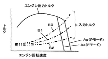
- FIG. 3 is a running performance diagram (torque diagram) showing the relationship between the engine speed and torque when the accelerator pedal 13 is fully depressed.
- characteristics Ap and Ae are torque diagrams when the travel mode is set to the P mode and the E mode, respectively.
- the maximum engine speed is not limited, whereas in the E mode, the maximum engine speed is limited to the low speed side with respect to the P mode.
- Characteristic B0-B2 is an example of input torque when the transmission 133 is driven by the engine 131, and the input torque increases as the engine speed increases.
- This input torque includes the input torque of the hydraulic pump 134, and the input torque changes as shown by characteristics B0-B2 according to the torque converter speed ratio e and the absorption torque of the hydraulic pump 134. Specifically, when the torque converter speed ratio e decreases, the input torque increases (characteristic B0), and when the torque converter speed ratio e increases, the input torque decreases (characteristic B2).
- the intersection of the characteristics Ap, Ae and the characteristics B0-B2 is a matching point, and the engine speed is the value of the matching point. For this reason, the engine speed for a predetermined input torque is higher in the P mode than in the E mode.
- the driving force is proportional to the square of the engine speed N. Therefore, in the P mode, the driving force for driving is larger than that in the E mode, and the maximum vehicle speed at each speed stage is increased by the amount of the higher engine rotation speed.
- FIG. 4 is a diagram showing the relationship between vehicle speed and driving force at each speed stage.
- the solid line represents the characteristics of the P mode and the dotted line represents the characteristics of the E mode.
- the driving force when the vehicle speed is slow, the driving force is large (low speed and high torque), and when the vehicle speed is high, the driving force is low (high speed and low torque).
- the smaller the speed stage the greater the driving force that can be obtained at the same vehicle speed. That is, the P mode has a larger maximum driving force and the maximum vehicle speed than the E mode.
- the maximum traveling driving force F2 in the P mode at the second speed stage is larger than the maximum traveling driving force F2 'in the E mode, and the maximum vehicle speed V2hi in the P mode is faster than the maximum vehicle speed V2'hi in the E mode.
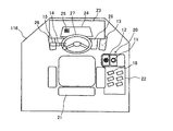
- FIG. 5 is a plan view showing the configuration inside the cab 116.
- a side console panel 22 and a work machine operating device 20 are provided on the right side of the driver seat 21.
- the front panel 23 in front of the driver's seat 21 is provided with a steering handle 27, the forward / reverse selector switch 14, and a monitor panel 24. Either the E mode or the P mode is selected for the monitor panel 24.
- a display unit 25 is provided for displaying whether or not.
- the speed stage switch 15 is provided at the front end of the forward / reverse selector switch 14. Further, an accelerator pedal 13 and left and right brake pedals 26 are provided in front of the driver's seat 21 and below the front panel 23.
- FIG. 7 is a schematic diagram showing the appearance of the work machine operating device 20 as viewed from the rear.
- the arm operation lever 11 is provided on the right side of the bucket operation lever 12 provided on the right side of the driver's seat 21.
- the above-described kick-down switches 16 and 17 are provided on the upper surface (top portion) and the left side surface (side surface on the driver's seat 21 side) of the grip 11a of the arm operation lever 11.
- the sub switch 19 for mode switching is provided on the left side surface (side surface on the driver's seat 21 side) of the grip 12a of the bucket operation lever 12.
- the sub switch 19 may be provided on the upper surface of the grip 12a instead of the left side of the grip 12a of the bucket operating lever 12 or in addition to the left side (that is, provided only on the upper surface (top) of the grip 12a.
- the arm operation lever 11 is provided with a detent mechanism 11b (schematically illustrated in FIG. 2) that maintains the posture at a position that instructs the arm raising operation.
- the kick-down switches 16 and 17 and the sub switch 19 are push button type switches, but in this embodiment, both are alternate type push buttons. Therefore, when the vehicle is traveling at a speed stage other than the first speed (when there is a lower speed stage), every time one of the kick-down switches 16 and 17 is operated once, it responds to the operation signal. Then, a downshift signal is output from the controller 136 to the transmission control unit 138, and the gear is shifted down to a low speed step by step. When the kickdown switch 16 or 17 is operated in the first step, the speed step selected by the speed step switch 15 is selected. Return to.
- the speed stage switch 15 when the first speed is selected by the speed stage switch 15, the speed stage does not shift from the first speed regardless of whether or not the kick down switches 16 and 17 are operated.
- the operation of the sub switch 19 is accepted by the controller 136 only when the E mode is selected by the main switch 18. That is, when the P mode is selected by the main switch 18, the traveling mode is fixed to the P mode, and even if the sub switch 19 is operated, a traveling mode switching signal is output from the controller 136 to the engine control unit 137. No, the driving mode does not switch to the E mode.
- the maximum rotational speed of the engine 131 is not limited, the driving force can be increased within the range of the capacity, and the maximum vehicle speed can be increased.
- the traveling mode is switched to the P mode.
- the sub switch 19 is pressed again, the mode returns to the E mode.
- the maximum rotational speed of the engine 131 is limited to the low speed side, the original maximum driving force and the maximum vehicle speed are suppressed, and fuel efficiency is improved.
- the traveling mode is repeatedly switched to the P mode, the E mode, the P mode,.
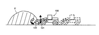
- FIG. 8 is a schematic view showing the state of scooping work of the excavated material when the excavated material such as earth or sand or gravel is loaded on a dump truck or the like by the wheel loader 100.
- the arm raising operation is held using the detent mechanism 11b of the arm operating lever 11.
- the bucket operating lever 12 is operated to cause the bucket 122 to perform a cloud operation, thereby scooping up the work to be excavated into the bucket 122.
- the driving force (traction force) is adjusted by depressing the accelerator pedal 13. At this time, it may be better not to increase the driving force more than necessary depending on the nature of the excavated object and the condition of the road surface, and a larger driving force may be required.
- the person switches the E mode and the P mode in a timely manner according to the situation judgment, and scoops the work to be excavated into the bucket 122 while avoiding the road surface from being drowned by the slip.
- the operator operates the (D) forward / reverse selector switch 14 to switch the traveling direction backward to move backward from the mountain P, and again switches the traveling direction to the front to dump. It moves to the vicinity of a truck (not shown) and operates the arm operation lever 11 and the bucket operation lever 12 to put the work to be excavated into the loading platform of the dump truck.
- the travel mode is switched to the P mode when the sub switch 19 is pressed. Since it is not necessary to release the hand 20 and switch the main switch 18 of the side console panel 22 to the P mode, good workability can be ensured. In addition, since the travel mode can be immediately switched to the P mode regardless of the speed stage by pressing the sub switch 19, for example, when traveling uphill at a second speed, the travel driving force is temporarily increased. Also useful. Further, after the travel mode is switched to the P mode by operating the sub switch 19, the travel mode can be returned to the E mode by operating the sub switch 19 again. Therefore, the driving mode can be arbitrarily switched according to the preference of the operator while the main switch 18 is operated in the E mode, and the mode switching operation can be quickly and easily performed to flexibly control the driving force. Can do.
- the arm operation lever 11 tends to vary depending on the situation and the preference of the operator, whether the hand grips the grip 11a firmly, puts it lightly, or grips from above or from the side. Therefore, in this embodiment, the bucket operation lever 12 is arranged on the left side close to the operator, the arm operation lever 11 is arranged on the right side far from the operator, and the kick-down switches 16 and 17 for forcibly shifting down the speed stage are provided on the arm.
- the operation lever 11 is provided at two locations on the upper surface and the left side surface of the grip 11a (that is, the side surface close to the driver's seat 21) so that the kick down switch 16 or 17 can be used for the kick down operation.
- the kick-down switch 17 disposed on the left side of the grip 11a is easy to operate with the right thumb coming to the left of the grip 11a, and when the grip 11a is gripped from the side (right side).
- the kick-down switch 16 provided on the upper surface of the grip 11a is easy to operate with the right thumb.
- the sub switch 19 can be operated with the bucket operation lever 12 held, and it is not necessary to release the hand from the work implement operation device 20 or change the operation lever to switch the traveling mode.
- the sub switch 19 is provided on the left side surface of the grip 12a, it is easy to switch the driving mode with the thumb of the right hand placed on the grip 12a.
- the kickdown switches 16 and 17 and the travel mode switching sub switch 19 are distributed to the arm operation lever 11 and the bucket operation lever 12 in consideration of the actual situation of the excavation work of the work to be excavated. By optimizing the operability, the operability can be further improved. Further, by distributing the kick down switches 16 and 17 and the travel mode switching sub switch 19 to the arm operating lever 11 and the bucket operating lever 12, it is possible to make it difficult to mistake the kick down operation and the traveling mode switching operation. Can also be suppressed.
- each switch 16, 17 and 19 can independently set the speed stage and the running mode. Since it can be selected, the installation space for each means of the kick-down operation and the switching operation of the traveling mode can be suppressed, and the installation space for the grips 11a and 12a of the arm operation lever 11 and the bucket operation lever 12 can be reduced.
- the switches 16, 17, 19 can be suitably arranged. The fact that the switches 16, 17, and 19 can be arranged on the grips 11a and 12a greatly contributes to the realization of the above high operability.
- switches 16, 17, and 19 are alternate types, for example, a plurality of kick-down switches are provided to directly select each speed stage, or two sub-switches for E mode and P mode selection are provided. Compared with the case where it is provided, since the travel mode and the speed stage can be arbitrarily set with one switch, the operation is also easy.
- the operator can appropriately display the display unit even if the sub-switch 19 frequently switches the driving mode. 25, the driving mode can be confirmed.
- the operator can easily set the travel mode according to his / her intention by performing the operation while confirming the travel mode as appropriate. For example, when the travel mode is the P mode, the E mode is selected.
- the accelerator pedal 13 is stepped on by misunderstanding that the vehicle is misunderstood, it is possible to suppress an erroneous operation such as the traveling driving force increasing against the operator's will and hitting the road surface.
- the sub switch 19 for switching the traveling mode is provided only on the left side surface of the grip 12a of the bucket operation lever 12 has been described as an example.
- the embodiment is not limited thereto.
- One sub switch 19 may be provided only on the upper surface of the grip 12a, or one (two) on the upper surface and the left side surface. Assuming that the grip 12a of the bucket operation lever 12 is gripped from the side, if the sub switch 19 for mode switching is located above the grip 12a of the bucket operation lever 12, it is easy to push with the right thumb.
- the gripping method of the bucket operation lever 12 varies depending on the operator, it is useful if the sub switch 19 is on both the upper surface and the left surface of the grip 12a of the bucket operation lever 12.
- the sub switch 19 is assumed to be an operation for switching the driving mode temporarily and for a short time. It can also be considered as a type switch.
- a mode switching signal is output from the controller 136 to the engine control unit 137 in accordance with the operation signal.
- the traveling mode is switched to the P mode only while the sub switch 19 is pressed, and the traveling mode returns to the E mode when the pressing of the sub switch 19 is stopped.
- control signal output from the controller 136 to the engine control unit 137 does not limit the maximum rotation speed of the engine 131 when the P mode is selected, and the engine 131 when the E mode is selected.
- the maximum rotation speed is limited to the low speed side, it is only necessary to shift the maximum engine rotation speed in the P mode to a higher speed side than that in the E mode, so the maximum engine rotation speed is unlimited in the P mode. There is no need.
- three or more driving modes having different upper limits of the engine maximum rotation speed may be prepared. In this case, each time the sub switch 19 is operated once, the traveling mode is switched in order so that the speed stage is changed by one stage every time the kick down switch 16 or 17 is operated once. preferable.
- the speed ratio detection means may have any configuration.
- the rotation of the engine 131 is transmitted to the front wheels 113 and the rear wheels 114 via the torque converter 132, the transmission 133, the propeller shaft 141, and the axle 142.
- any configuration of the traveling drive force transmission mechanism may be used.
- the kick-down switches 16 and 17 can be installed at two places on the upper surface of the grip of the operation lever and the side surface on the driver's seat 21 side. Similar to the downshifting operation by the kickdown switches 16 and 17, the shifting operation by the sub switch 19 is also common as an operation related to the traction force. If the sub switch 19 is installed at two positions of the grip, the earth and sand can be changed depending on the operator and the situation. This can contribute to improved operability during scooping.
- the arm operating lever 11 and the bucket operating lever 12 may be provided on the left side of the driver's seat 21.
- the bucket operation lever 12 is preferably disposed on the driver seat 21 side of the arm operation lever 11, but the arm operation lever 12 may be provided on the driver seat side.
- the kick-down switches 16 and 17 and the sub switch 19 which are arranged on the side surface of the grip 11a of the arm operation lever 11 or the side surface of the grip 12a of the bucket operation lever 12 are as described above when the grip is gripped from above. Therefore, the grips 11a and 12a are arranged on the side surface of the driver's seat 21 side. Therefore, when the arm operation lever 11 and the bucket operation lever 12 are provided on the left side of the driver's seat 21, the kick down switches 16 and 17 are disposed on the upper surface and the right side surface of the grip 11 a of the arm operation lever 11.
- the sub switch 19 is provided on the side surface of the grip 12a of the bucket operation lever 12 disposed on the left side of the driver seat 21, the sub switch 19 is disposed on the side surface of the grip 12a on the driver seat 21 side, that is, the right side surface. .
Landscapes
- Engineering & Computer Science (AREA)
- Mining & Mineral Resources (AREA)
- Civil Engineering (AREA)
- General Engineering & Computer Science (AREA)
- Structural Engineering (AREA)
- Mechanical Engineering (AREA)
- Physics & Mathematics (AREA)
- General Physics & Mathematics (AREA)
- Automation & Control Theory (AREA)
- Operation Control Of Excavators (AREA)
- Component Parts Of Construction Machinery (AREA)
Abstract
Description
上記のように大きな走行駆動力を一時的に必要とする場合、サブスイッチ19を押圧操作すれば走行モードがPモードに切り換わるので、掘削作業中に作業機操作装置20から手を離してサイドコンソールパネル22のメインスイッチ18をPモードに切換操作する必要がないため、良好な作業性が確保できる。また、サブスイッチ19の押圧操作により速度段に関係なく即座に走行モードをPモードに切り換えることができるので、例えば2速で登坂走行をしている場合に一時的に走行駆動力を増大させる場合にも有用である。また、サブスイッチ19の操作により走行モードがPモードに切り換わった後、もう一度サブスイッチ19を操作すれば走行モードをEモードに戻すことができる。このためメインスイッチ18をEモードに操作したままの状態で、操作者の好みで走行モードを任意に切り換えることができ、モード切換の操作を迅速かつ容易に行い柔軟に走行駆動力をコントロールすることができる。
キックダウンスイッチ16,17やモード切換用のサブスイッチ19をオルタネイト式スイッチとしたことにより、各スイッチ16,17,19がそれぞれ単体で速度段や走行モードを任意に選択することができるので、キックダウン操作及び走行モードの切換操作の各手段の設置スペースを抑制することができ、アーム操作レバー11やバケット操作レバー12の各グリップ11a,12aの小さな設置スペースにそれらスイッチ16,17,19を好適に配置することができる。こうしてグリップ11a,12aにスイッチ16,17,19を配置できたことが上記の高い操作性の実現に大きく寄与している。また、これらスイッチ16,17,19がオルタネイト式であるため、例えば各速度段をそれぞれダイレクトに選択するために複数のキックダウンスイッチを設けたり、Eモード及びPモード選択用の2つのサブスイッチを設けたりする場合に比べ、1つのスイッチで走行モードや速度段を任意に設定することができるので操作も簡単である。
選択されている走行モードがモニタパネル24の表示部25に随時表示されるので、サブスイッチ19によって頻繁も走行モードを切り換えても、操作者は適宜表示部25で走行モードを確認することができる。これにより操作者は適宜走行モードを確認しながら操作を行うことで、自らの意図に沿った走行モードの設定操作がし易く、例えば走行モードがPモードになっているところ、Eモードが選択されていると勘違いしてアクセルペダル13を踏み込んだ際等に、操作者の意に反して走行駆動力が上昇し路面を抉ってしまう等の誤操作を抑制することができる。
11a グリップ
11b デテント機構
12 バケット操作レバー
12a グリップ
16,17 キックダウンスイッチ
19 サブスイッチ(モード切換スイッチ)
20 作業機操作装置
21 運転席
25 表示部(表示手段)
100 ホイールローダ
110 車体
113 前輪
114 後輪
120 作業機
121 アーム
122 バケット
123 アームシリンダ
124 バケットシリンダ
Claims (6)
- 車輪を有する車体と、
この車体の前部に取り付けた作業機と、
この作業機の動作を指示する作業機操作装置とを備え、
当該作業機操作装置が、
運転席の側部に設けた前記作業機の動作指示用の操作レバーと、
前記操作レバーのグリップの上面及び前記運転席側の側面に設けた、牽引力に関する操作をするための2つのスイッチと
を備えていることを特徴とするホイールローダ。 - 請求項1のホイールローダにおいて、
前記作業機は、アーム及びバケット、並びにこれらアーム及びバケットを駆動するアームシリンダ及びバケットシリンダを有していて、
前記作業機操作装置が、
前記操作レバーであって前記アームシリンダの動作指示用のアーム操作レバーと、
このアーム操作レバーの前記運転席側に併設された、前記バケットシリンダの動作指示用のバケット操作レバーと、
前記アーム操作レバーのグリップの上面及び前記運転席側の側面に設けた前記2つのスイッチであって、速度段を強制的にシフトダウンさせる2つのキックダウンスイッチと、
前記バケット操作レバーのグリップの前記運転席側の側面に設けた、エンジン最大回転速度の上限値が異なる複数の走行モードを切り換えるモード切換スイッチと
を備えていることを特徴とするホイールローダ。 - 請求項2のホイールローダにおいて、
前記モード切換スイッチが、前記バケット操作レバーのグリップの前記運転席側の側面に代えて又は当該運転席側の側面に加えて、当該グリップの上面に設けられていることを特徴とするホイールローダ。 - 請求項2又は3のホイールローダにおいて、前記モード切換スイッチは押しボタンであり、エンジン最大回転速度を上限が異なる複数の走行モードの切り換えを単体で指示することを特徴とするホイールローダ。
- 請求項2-4のいずれかのホイールローダにおいて、前記モード切換スイッチにより選択されている走行モードを表示する表示手段を備えていることを特徴とするホイールローダ。
- 請求項2-5のいずれかのホイールローダにおいて、アーム上げ動作を指示するポジションで前記アーム操作レバーの姿勢を維持するデテント機構を備えていることを特徴とするホイールローダ。
Priority Applications (5)
| Application Number | Priority Date | Filing Date | Title |
|---|---|---|---|
| EP12758204.7A EP2687638B1 (en) | 2011-03-15 | 2012-03-15 | Wheel loader |
| JP2012547350A JP5814258B2 (ja) | 2011-03-15 | 2012-03-15 | ホイールローダ |
| US13/996,247 US20140003900A1 (en) | 2011-03-15 | 2012-03-15 | Wheel loader |
| CN201280008246.2A CN103370479B (zh) | 2011-03-15 | 2012-03-15 | 轮式装载机 |
| KR1020137020848A KR101882406B1 (ko) | 2011-03-15 | 2012-03-15 | 휠 로더 |
Applications Claiming Priority (2)
| Application Number | Priority Date | Filing Date | Title |
|---|---|---|---|
| JP2011057076 | 2011-03-15 | ||
| JP2011-057076 | 2011-03-15 |
Publications (1)
| Publication Number | Publication Date |
|---|---|
| WO2012124767A1 true WO2012124767A1 (ja) | 2012-09-20 |
Family
ID=46830832
Family Applications (1)
| Application Number | Title | Priority Date | Filing Date |
|---|---|---|---|
| PCT/JP2012/056714 Ceased WO2012124767A1 (ja) | 2011-03-15 | 2012-03-15 | ホイールローダ |
Country Status (6)
| Country | Link |
|---|---|
| US (1) | US20140003900A1 (ja) |
| EP (1) | EP2687638B1 (ja) |
| JP (1) | JP5814258B2 (ja) |
| KR (1) | KR101882406B1 (ja) |
| CN (1) | CN103370479B (ja) |
| WO (1) | WO2012124767A1 (ja) |
Cited By (4)
| Publication number | Priority date | Publication date | Assignee | Title |
|---|---|---|---|---|
| CN103671888A (zh) * | 2013-12-18 | 2014-03-26 | 徐州凯尔农业装备股份有限公司 | 轮式拖拉机电控换挡装置 |
| JP2022094662A (ja) * | 2020-12-15 | 2022-06-27 | 株式会社クボタ | 作業車 |
| WO2023100602A1 (ja) | 2021-12-02 | 2023-06-08 | 株式会社小松製作所 | キャブ及び作業機械 |
| JP2024113876A (ja) * | 2023-02-10 | 2024-08-23 | ヤンマーホールディングス株式会社 | 作業機械 |
Families Citing this family (13)
| Publication number | Priority date | Publication date | Assignee | Title |
|---|---|---|---|---|
| JP6034773B2 (ja) * | 2013-11-13 | 2016-11-30 | 株式会社クボタ | 作業機 |
| EP2891783B1 (en) * | 2014-10-31 | 2016-11-30 | Komatsu Ltd. | Wheel loader and wheel loader control method |
| JP6587279B2 (ja) * | 2015-07-03 | 2019-10-09 | キャタピラー エス エー アール エル | 建設機械における走行制御システム |
| US10041229B2 (en) * | 2015-11-02 | 2018-08-07 | Caterpillar Inc. | System and method for controlling operation of machine |
| JP6487822B2 (ja) * | 2015-11-05 | 2019-03-20 | ヤンマー株式会社 | トラクタ |
| CN108301457B (zh) * | 2018-03-14 | 2021-02-19 | 华侨大学 | 一种挖掘机启停控制方法 |
| JP6806726B2 (ja) * | 2018-03-27 | 2021-01-06 | 日立建機株式会社 | 作業車両 |
| EP3815983B1 (en) * | 2018-06-29 | 2026-04-08 | Kubota Corporation | Work machine |
| CN109515537B (zh) * | 2018-11-16 | 2020-06-09 | 中联重科股份有限公司 | 履带式车辆行走机构的控制方法、系统及履带式车辆 |
| EP4015277A1 (en) * | 2020-12-15 | 2022-06-22 | Kubota Corporation | Work vehicle, control method, control program and recording medium |
| JP2022102299A (ja) * | 2020-12-25 | 2022-07-07 | 株式会社クボタ | 作業車 |
| CN112982538B (zh) * | 2021-02-24 | 2022-06-21 | 索特传动设备有限公司 | 一种轮式装载机的控制方法、装置、轮式装载机及存储介质 |
| CN113513582A (zh) * | 2021-08-27 | 2021-10-19 | 德州德工机械有限公司 | 工程车辆自动变速箱用电控换挡手柄及其控制方法 |
Citations (2)
| Publication number | Priority date | Publication date | Assignee | Title |
|---|---|---|---|---|
| JP2006052632A (ja) * | 2004-06-22 | 2006-02-23 | Caterpillar Inc | 作業機械ジョイスティック制御システム |
| WO2010147232A1 (ja) | 2009-06-19 | 2010-12-23 | 日立建機株式会社 | 作業車両の原動機制御装置 |
Family Cites Families (12)
| Publication number | Priority date | Publication date | Assignee | Title |
|---|---|---|---|---|
| JP2000105618A (ja) * | 1998-07-28 | 2000-04-11 | Komatsu Ltd | レバ―式信号発生装置 |
| US6098481A (en) * | 1998-12-15 | 2000-08-08 | Caterpillar Inc. | High force variable position detent mechanism |
| US6643577B1 (en) * | 2002-08-22 | 2003-11-04 | Caterpillar Inc | Operator control station and method for a work machine having more than one function |
| FR2858861B1 (fr) * | 2003-08-11 | 2007-06-22 | Manitou Bf | Dispositif de commande par interaction avec la main d'un operateur |
| KR100621982B1 (ko) * | 2004-04-13 | 2006-09-14 | 볼보 컨스트럭션 이키프먼트 홀딩 스웨덴 에이비 | 중장비의 기능스위치 패턴설정장치 |
| JP4785522B2 (ja) * | 2005-12-22 | 2011-10-05 | 株式会社小松製作所 | 作業車両のエンジン制御装置 |
| US9074352B2 (en) * | 2006-03-27 | 2015-07-07 | John R. Ramun | Universal control scheme for mobile hydraulic equipment and method for achieving the same |
| US7784581B1 (en) * | 2006-09-14 | 2010-08-31 | Deere & Company | Machine control interlocks for an electrohydraulically controlled vehicle |
| WO2009048364A1 (en) * | 2007-10-08 | 2009-04-16 | Svab Hydraulik Ab | A control lever for operating a machine, a procedure for operating a machine via a control lever and the use of the control lever |
| US8230757B2 (en) * | 2008-07-29 | 2012-07-31 | Deere & Company | Lever lockout assembly |
| JP5238448B2 (ja) * | 2008-10-20 | 2013-07-17 | キャタピラー エス エー アール エル | 作業車両 |
| DE102009034154A1 (de) * | 2009-07-20 | 2011-02-03 | Claas Selbstfahrende Erntemaschinen Gmbh | Multifunktionsgriff |
-
2012
- 2012-03-15 KR KR1020137020848A patent/KR101882406B1/ko active Active
- 2012-03-15 US US13/996,247 patent/US20140003900A1/en not_active Abandoned
- 2012-03-15 JP JP2012547350A patent/JP5814258B2/ja active Active
- 2012-03-15 CN CN201280008246.2A patent/CN103370479B/zh active Active
- 2012-03-15 EP EP12758204.7A patent/EP2687638B1/en active Active
- 2012-03-15 WO PCT/JP2012/056714 patent/WO2012124767A1/ja not_active Ceased
Patent Citations (2)
| Publication number | Priority date | Publication date | Assignee | Title |
|---|---|---|---|---|
| JP2006052632A (ja) * | 2004-06-22 | 2006-02-23 | Caterpillar Inc | 作業機械ジョイスティック制御システム |
| WO2010147232A1 (ja) | 2009-06-19 | 2010-12-23 | 日立建機株式会社 | 作業車両の原動機制御装置 |
Cited By (7)
| Publication number | Priority date | Publication date | Assignee | Title |
|---|---|---|---|---|
| CN103671888A (zh) * | 2013-12-18 | 2014-03-26 | 徐州凯尔农业装备股份有限公司 | 轮式拖拉机电控换挡装置 |
| JP2022094662A (ja) * | 2020-12-15 | 2022-06-27 | 株式会社クボタ | 作業車 |
| JP7482766B2 (ja) | 2020-12-15 | 2024-05-14 | 株式会社クボタ | 作業車 |
| WO2023100602A1 (ja) | 2021-12-02 | 2023-06-08 | 株式会社小松製作所 | キャブ及び作業機械 |
| JP2023082323A (ja) * | 2021-12-02 | 2023-06-14 | 株式会社小松製作所 | キャブ及び作業機械 |
| JP7890817B2 (ja) | 2021-12-02 | 2026-07-15 | 株式会社小松製作所 | キャブ及び作業機械 |
| JP2024113876A (ja) * | 2023-02-10 | 2024-08-23 | ヤンマーホールディングス株式会社 | 作業機械 |
Also Published As
| Publication number | Publication date |
|---|---|
| US20140003900A1 (en) | 2014-01-02 |
| CN103370479A (zh) | 2013-10-23 |
| EP2687638A1 (en) | 2014-01-22 |
| JP5814258B2 (ja) | 2015-11-17 |
| EP2687638A4 (en) | 2014-12-17 |
| JPWO2012124767A1 (ja) | 2014-07-24 |
| KR101882406B1 (ko) | 2018-07-26 |
| EP2687638B1 (en) | 2017-05-10 |
| KR20140051120A (ko) | 2014-04-30 |
| CN103370479B (zh) | 2016-06-01 |
Similar Documents
| Publication | Publication Date | Title |
|---|---|---|
| JP5814258B2 (ja) | ホイールローダ | |
| EP2444636B1 (en) | Motor control device for working vehicle | |
| CN101835968B (zh) | 作业车辆的原动机控制装置 | |
| US8777808B2 (en) | Working vehicle control apparatus | |
| US7865288B2 (en) | Engine control device for working vehicle | |
| JP5503954B2 (ja) | 作業車両のクラッチ制御装置 | |
| US8775034B2 (en) | Shift control system for industrial vehicle | |
| US9091221B2 (en) | Engine speed control device for industrial vehicle | |
| KR20090083486A (ko) | 산업 차량의 변속 제어 장치 | |
| US9383002B2 (en) | Operation vehicle travel control device | |
| JPH10121522A (ja) | 建設機械車両の作業機および変速機シフトの制御装置 | |
| JP5017291B2 (ja) | 作業車両の変速制御装置 | |
| JP7236917B2 (ja) | 作業車両、作業車両の制御装置および制御方法 | |
| JP2011122706A (ja) | 作業車両のクラッチ制御装置 |
Legal Events
| Date | Code | Title | Description |
|---|---|---|---|
| ENP | Entry into the national phase |
Ref document number: 2012547350 Country of ref document: JP Kind code of ref document: A |
|
| 121 | Ep: the epo has been informed by wipo that ep was designated in this application |
Ref document number: 12758204 Country of ref document: EP Kind code of ref document: A1 |
|
| REEP | Request for entry into the european phase |
Ref document number: 2012758204 Country of ref document: EP |
|
| WWE | Wipo information: entry into national phase |
Ref document number: 2012758204 Country of ref document: EP |
|
| WWE | Wipo information: entry into national phase |
Ref document number: 13996247 Country of ref document: US |
|
| ENP | Entry into the national phase |
Ref document number: 20137020848 Country of ref document: KR Kind code of ref document: A |
|
| NENP | Non-entry into the national phase |
Ref country code: DE |