WO2012127630A1 - 生体認証システム、生体認証方法及び生体認証プログラム - Google Patents
生体認証システム、生体認証方法及び生体認証プログラム Download PDFInfo
- Publication number
- WO2012127630A1 WO2012127630A1 PCT/JP2011/056848 JP2011056848W WO2012127630A1 WO 2012127630 A1 WO2012127630 A1 WO 2012127630A1 JP 2011056848 W JP2011056848 W JP 2011056848W WO 2012127630 A1 WO2012127630 A1 WO 2012127630A1
- Authority
- WO
- WIPO (PCT)
- Prior art keywords
- biometric
- unit
- information
- data
- fingerprint
- Prior art date
- Legal status (The legal status is an assumption and is not a legal conclusion. Google has not performed a legal analysis and makes no representation as to the accuracy of the status listed.)
- Ceased
Links
Images








Classifications
-
- G—PHYSICS
- G06—COMPUTING OR CALCULATING; COUNTING
- G06V—IMAGE OR VIDEO RECOGNITION OR UNDERSTANDING
- G06V30/00—Character recognition; Recognising digital ink; Document-oriented image-based pattern recognition
- G06V30/10—Character recognition
- G06V30/24—Character recognition characterised by the processing or recognition method
- G06V30/242—Division of the character sequences into groups prior to recognition; Selection of dictionaries
-
- G—PHYSICS
- G06—COMPUTING OR CALCULATING; COUNTING
- G06F—ELECTRIC DIGITAL DATA PROCESSING
- G06F21/00—Security arrangements for protecting computers, components thereof, programs or data against unauthorised activity
- G06F21/30—Authentication, i.e. establishing the identity or authorisation of security principals
- G06F21/31—User authentication
- G06F21/32—User authentication using biometric data, e.g. fingerprints, iris scans or voiceprints
-
- G—PHYSICS
- G06—COMPUTING OR CALCULATING; COUNTING
- G06V—IMAGE OR VIDEO RECOGNITION OR UNDERSTANDING
- G06V10/00—Arrangements for image or video recognition or understanding
- G06V10/98—Detection or correction of errors, e.g. by rescanning the pattern or by human intervention; Evaluation of the quality of the acquired patterns
- G06V10/993—Evaluation of the quality of the acquired pattern
-
- G—PHYSICS
- G06—COMPUTING OR CALCULATING; COUNTING
- G06V—IMAGE OR VIDEO RECOGNITION OR UNDERSTANDING
- G06V10/00—Arrangements for image or video recognition or understanding
- G06V10/20—Image preprocessing
- G06V10/25—Determination of region of interest [ROI] or a volume of interest [VOI]
-
- G—PHYSICS
- G06—COMPUTING OR CALCULATING; COUNTING
- G06V—IMAGE OR VIDEO RECOGNITION OR UNDERSTANDING
- G06V40/00—Recognition of biometric, human-related or animal-related patterns in image or video data
- G06V40/10—Human or animal bodies, e.g. vehicle occupants or pedestrians; Body parts, e.g. hands
- G06V40/12—Fingerprints or palmprints
- G06V40/1382—Detecting the live character of the finger, i.e. distinguishing from a fake or cadaver finger
- G06V40/1388—Detecting the live character of the finger, i.e. distinguishing from a fake or cadaver finger using image processing
Definitions
- the present invention relates to a biometric authentication system, a biometric authentication method, and a biometric authentication program.
- biometric authentication technology authentication methods include “1: 1 authentication” and “1: N authentication”.
- 1: 1 authentication refers to a method of performing authentication by comparing biometric information input by a user with biometric information registered in advance in association with user identification information.
- the 1: N authentication refers to a method of authenticating by comparing biometric information input by a user with biometric information of N people registered in advance.
- 1-to-N authentication when 1-to-N authentication is adopted, biometric data input by a user is collated with biometric data of N persons registered in advance, so the number N of biometric data registered is large. It takes time until the authentication result is output.
- fingerprint collation that narrows down a registered fingerprint to be collated with an input fingerprint by comparing a selection parameter representing a feature amount of the fingerprint between the input fingerprint and the registered fingerprint.
- a selection parameter representing a feature amount of the fingerprint between the input fingerprint and the registered fingerprint.
- the ratio of the ridge area to the entire fingerprint area, the distance between the ridge and valley lines, the number of end points or branch points of the fingerprint ridge or valley line, etc. are selected as the selection parameters before collation. Compare.
- the conventional technology has a problem that the accuracy of narrowing down is not stable as described below.
- the above-described fingerprint collation device performs narrowing down on the assumption that there is no change in the fingerprint between the time when the fingerprint is registered and the time when the registered fingerprint is used for authentication if the same user. For this reason, the above-described fingerprint collation device cannot cope with narrowing down when a temporary change occurs in the living body due to scratches or rough skin. This is because when the fingerprint is temporarily changed due to scratches, rough skin, or the like, the difference in the selection parameter compared between the input fingerprint and the registered fingerprint increases even for the same user's fingerprint. Therefore, even if the registered fingerprint is narrowed down by comparing the selection parameter between the input fingerprint and the registered fingerprint, the above-described fingerprint collation device verifies the registered fingerprint of the user who entered the fingerprint with the input fingerprint. There are cases where it is not narrowed down to the registered fingerprint.
- the disclosed technology has been made in view of the above, and an object thereof is to provide a biometric authentication system, a biometric authentication method, and a biometric authentication program that can stabilize the accuracy of narrowing down.
- the biometric authentication system disclosed in the present application includes biometric-specific feature region position information on an image of biometric information that has succeeded in biometric authentication, and reference biometric information that is referred to when the biometric authentication is successful. Are registered and recorded in the storage unit.
- the biometric authentication system includes a detection unit that detects a biometric characteristic region from an input image of biometric information to be authenticated.
- the biometric authentication system includes the reference biometric information stored in the storage unit based on the position information of the feature region detected by the detection unit and the position information of the region stored in the storage unit. It has a narrowing-down unit that narrows down the biometric information for reference to be compared with the biometric information to be authenticated.
- the biometric authentication system includes an authentication unit that performs authentication by comparing biometric information for reference narrowed down by the narrowing-down unit and biometric information to be authenticated.
- FIG. 1 is a diagram illustrating the configuration of the biometric authentication system according to the first embodiment.
- FIG. 2 is a block diagram illustrating the configuration of each device included in the biometric authentication system according to the first embodiment.
- FIG. 3 is a diagram for explaining a fingerprint image cutting method.
- FIG. 4A is a diagram for explaining the classification of the low quality region.
- FIG. 4B is a diagram for explaining the classification of the low quality region.
- FIG. 4C is a diagram for explaining the classification of the low quality region.
- FIG. 4D is a diagram for explaining the classification of the low quality region.
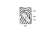
- FIG. 5 is a diagram illustrating an example of a fingerprint image.
- FIG. 6 is a diagram showing block identification numbers.
- FIG. 7 is a diagram showing a fingerprint image divided into blocks.
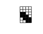
- FIG. 8 is a diagram illustrating a detection result of the low quality region.
- FIG. 9 is a diagram illustrating an example of a fingerprint image.
- FIG. 10 is a diagram illustrating a detection result of the low quality region.
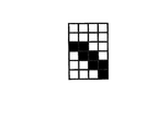
- FIG. 11 is a diagram showing a low quality region after correction.
- FIG. 12 is a diagram illustrating an example of a fingerprint image.
- FIG. 13 is a diagram illustrating a detection result of the low quality region.
- FIG. 14 is a diagram showing a low quality region after correction.
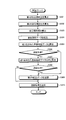
- FIG. 15 is a flowchart illustrating a procedure of login processing according to the first embodiment.
- FIG. 16 is a flowchart illustrating a procedure of biometric authentication processing according to the first embodiment.
- FIG. 17 is a schematic diagram illustrating an example of a computer that executes a biometric authentication program according to the first and second embodiments.
- FIG. 1 is a diagram illustrating the configuration of the biometric authentication system according to the first embodiment.
- the biometric authentication system 1 shown in FIG. 1 accommodates terminal devices 10A to 10C and an authentication server 30.
- the authentication server 30 has a 1: N ratio between the user's fingerprint data input by any of the terminal devices 10A to 10C and a plurality of pre-registered fingerprint data. Assume that fingerprint authentication is executed.
- terminal devices 10A to 10C and the authentication server 30 are communicably connected via the network 3.
- a communication network such as the Internet (Internet), a LAN (Local Area Network), or a VPN (Virtual Private Network) is employed.
- terminal device 10 In the example of FIG. 1, three terminal devices and one authentication server are illustrated, but the disclosed system is not limited to the illustrated configuration. That is, the biometric authentication system 1 only needs to accommodate at least one terminal device and one authentication server, and can accommodate any number of terminal devices and authentication servers. In the following, when the devices 10A to 10C are described without distinction, they may be expressed as “terminal device 10”.
- the terminal device 10 is an information processing device used by a user.
- a mobile terminal such as a mobile phone, a PHS (Personal Handyphone System), a PDA (Personal Digital Assistant), a smartphone, as well as a fixed terminal such as a personal computer (PC).
- PC personal computer
- the terminal device 10 accepts an input of a user's fingerprint image instead of an account and a password when logging in to the own device, and the user of the terminal device 10 according to a result of fingerprint authentication executed by the authentication server 30 described later. Allow or disallow login for.
- the terminal device 10 creates fingerprint data to be used when fingerprint authentication is executed by the authentication server 30 described later, from an image whose fingerprint is read by a fingerprint sensor (not shown).
- a fingerprint image an image in which a fingerprint is read by the fingerprint sensor of the terminal device 10 may be referred to as a “fingerprint image”.
- fingerprint data created from a fingerprint image is referred to as “input fingerprint data”, and fingerprint data registered in advance in the authentication server 30 described later is referred to as “registered fingerprint data”. There is a case.
- the terminal device 10 creates narrowed data to be used when registered fingerprint data to be collated with input fingerprint data is narrowed by the authentication server 30 described later from the fingerprint image read by the fingerprint sensor.
- narrowed-down data created from a fingerprint image is referred to as “input narrowed-down data”
- narrowed-down data registered in advance in the authentication server 30 described later is referred to as “registered narrowed-down data”. May be written.
- the terminal device 10 transmits fingerprint data and narrowed-down data created from the fingerprint image to the authentication server 30 described later.
- the terminal device 10 since the terminal device 10 sends the fingerprint data and the narrowed-down data created from the fingerprint image, not the fingerprint image itself, to the network 3, it is possible to prevent the user's personal information such as the fingerprint from leaking outside.
- the terminal device 10 creates the fingerprint data and the narrowed-down data from the fingerprint image is illustrated, but the terminal device 10 transmits the fingerprint image to the authentication server 30 as it is, and the fingerprint data and the narrowed-down data are sent to the authentication server 30. It is also possible to create embedded data.
- the terminal device 10 permits the user to log in to the terminal device 10 when the authentication result by the authentication server 30 described later is an authentication success. That is, the terminal device 10 logs in the user by automatically inputting an account and a password. As a result, the security of user authentication is improved compared to password authentication, and the risk of a password being forgotten or leaked is reduced.
- the terminal device 10 prohibits the user from logging in to the terminal device 10 when the authentication result by the authentication server 30 described later is an authentication failure.
- the terminal device 10 may output a notification that prompts the user to input the fingerprint image again, may output a warning that the terminal device 10 is not authorized to use, The operation of the terminal device 10 may be locked.
- the authentication server 30 is a server device that provides a fingerprint authentication service.
- the authentication server 30 uses the input narrowed data and the registered narrowed data to check with the input fingerprint data prior to the fingerprint authentication. Narrow down the data.
- the authentication server 30 narrows down the registered fingerprint data corresponding to the registered narrowed data whose narrowing similarity calculated from the input narrowed data and the registered narrowed data is equal to or greater than a predetermined threshold.
- the authentication server 30 performs authentication by comparing the input fingerprint data with the registered fingerprint data obtained as a result of narrowing down.
- the authentication server 30 has a collation similarity calculated from the input fingerprint data and the registered fingerprint data equal to or greater than a predetermined threshold until the input fingerprint data is collated with all the registered fingerprint data previously narrowed down. The process of determining whether or not is repeated.
- the authentication server 30 replies to the terminal device 10 that the authentication of the input fingerprint data is successful when the collation similarity with the at least one registered fingerprint data is equal to or greater than the threshold value.
- the authentication server 30 responds to the terminal device 10 that the authentication of the input fingerprint data has failed when the matching similarity with all the registered fingerprint data is less than the threshold value.
- the biometric authentication system 1 according to the present embodiment is referred to when the fingerprint authentication is successful and the position information of the region in which the unique features of the fingerprint are unclear on the fingerprint image corresponding to the input fingerprint data that has been successfully authenticated.
- the registered fingerprint data is associated with the registered fingerprint data and registered in the storage unit. After that, the biometric authentication system 1 according to the present embodiment detects an area where the characteristic unique to the fingerprint is unclear from the fingerprint image corresponding to the newly input fingerprint data.
- the biometric authentication system 1 according to the present embodiment uses the registered fingerprint stored in the storage unit based on the similarity between the position information of the region obtained as a detection result and the position information of the region stored in the storage unit.
- the registered fingerprint data to be collated with the input fingerprint data is narrowed down. Furthermore, the biometric authentication system 1 according to the present embodiment performs authentication by collating the registered fingerprint data obtained as a narrowing result with the input fingerprint data.
- the biometric authentication system 1 even if the fingerprint of the user changes due to the scratch or the rough skin, the characteristic unique to the fingerprint on the fingerprint image due to the scratch or the rough skin when the authentication is successful.
- the position information of the unclear area is added to the registered fingerprint data as narrowed-down data. For this reason, in the biometric authentication system 1 according to the present embodiment, when fingerprint data having scratches or rough skin is input in subsequent authentication, registered fingerprint data having position information similar to the position information of the region is narrowed down. . Therefore, in the biometric authentication system 1 according to the present embodiment, the probability that the registered fingerprint data of the user who has input the fingerprint is included in the narrowed-down result is increased.
- the biometric authentication system 1 it is possible to stabilize the accuracy of narrowing down. Furthermore, in the biometric authentication system 1 according to the present embodiment, since the probability that the registered fingerprint data of the user himself / herself is included in the narrowing-down result increases, it is possible to prevent the authentication from failing in conjunction with the narrowing-down failure, The authentication time from when the fingerprint is input to when the authentication result is output can be shortened.
- FIG. 2 is a block diagram illustrating the configuration of each device included in the biometric authentication system according to the first embodiment.
- the terminal device 10 includes a communication I / F (Interface) unit 11, a fingerprint sensor 12, a fingerprint data creation unit 13, a narrowed data creation unit 14, and an OS (Operating System) execution unit. 15.
- the terminal device 10 has functions other than the function units shown in FIG. 2 such as various function units of a known PC, such as various input devices and audio output devices.
- the communication I / F unit 11 is an interface for performing communication control with another device, for example, the authentication server 30.
- the communication I / F unit 11 transmits fingerprint data created by a fingerprint data creating unit 13 described later or narrowed data created by a narrowed data creating unit 14 described later to the authentication server 30, or An authentication result is received from the authentication server 30.
- a network interface card such as a LAN card or a modem can be employed.
- the fingerprint sensor 12 is a sensor that reads a fingerprint.
- a mode in which the fingerprint sensor 12 is built in the terminal device 10 can be adopted, and a mode in which the fingerprint sensor 12 is connected to the terminal device 10 by USB (Universal Serial Bus) or the like can be adopted.
- USB Universal Serial Bus
- any detection method such as a capacitance type, an electric field detection type, an optical type, a thermal type, and a pressure type can be adopted.
- a finger type that is, a slide type that slides the center part inside the fingertip, or a stamp type that places a finger bar may be used. Absent.
- the fingerprint data creation unit 13 is a processing unit that creates fingerprint data used for fingerprint authentication from a fingerprint image.
- the fingerprint data creation unit 13 is read by the fingerprint sensor 12 in accordance with an arbitrary authentication method such as a minutia method, a pattern matching method, or a frequency analysis method adopted by an authentication unit 36 of the authentication server 30 described later. Create fingerprint data from the fingerprint image.
- the fingerprint data creation unit 13 determines the direction of the feature points such as the end points and branch points of ridges included in the fingerprint image pattern, the positional relationship, A correlation between feature points is created as fingerprint data. Further, when the pattern matching method is adopted by the authentication unit 36 described later, the fingerprint data creation unit 13 creates an image in which the fingerprint image is binarized or thinned as fingerprint data. Further, when the frequency analysis method is adopted by the authentication unit 36 to be described later, the fingerprint data creation unit 13 uses, as fingerprint data, a waveform spectrum series when a section obtained by slicing a pattern pattern of a fingerprint image is regarded as a waveform. create.
- the narrowed data creation unit 14 is a processing unit that creates narrowed data used for narrowing registered fingerprint data from a fingerprint image. As shown in FIG. 2, the narrowed data creation unit 14 includes a dividing unit 14a, a first creation unit 14b, a detection unit 14c, a second creation unit 14d, and a correction unit 14e.
- the dividing unit 14a is a processing unit that divides the fingerprint image into blocks of a predetermined size.
- the dividing unit 14a detects a fingerprint reference point, for example, a fingerprint center that is the center of a pattern (vortex) forming the fingerprint, by searching for a fingerprint image read by the fingerprint sensor 12. Then, the dividing unit 14a cuts out a target area for subsequent processing, for example, creation of narrowed-down data, etc. from the fingerprint image based on the fingerprint center detected by searching for the fingerprint image. Divide the image into blocks.
- FIG. 3 is a diagram for explaining a fingerprint image cutting method.
- the dividing unit 14 a searches for the fingerprint image 20 read by the fingerprint sensor 12. With this search, the dividing unit 14a detects the fingerprint center 21 that is the center of the pattern forming the fingerprint from the fingerprint image 20. Then, the dividing unit 14a sets a cutout region 22 of the fingerprint image 20 having the fingerprint center 21 in the fingerprint image 20 as the center or the center of gravity. At this time, the dividing unit 14a sets, as the cutout region 22, a rectangle in which the major axis direction 23 is perpendicular to the wrinkles of the first joint of the finger, that is, the fingertip direction.
- the dividing unit 14a sets the size of the cutout region 22 to a size that can be divided into a predetermined number of blocks. Thereafter, the dividing unit 14a extracts the cutout fingerprint image 24 by cutting out the cutout region 22 from the fingerprint image 20.
- the dividing unit 14a uses reference information transmitted from a first creation unit 14b and a second creation unit 14d, which will be described later, for example, the type of singular point used as a reference point for a fingerprint, the size of the cutout region 22, and the like. Then, the fingerprint image 20 is cut out. In addition, the dividing unit 14a previously cuts out using the same cutting method as that used when creating the first narrowed data and the second narrowed data registered in the storage unit 32 of the authentication server 30. It can also be defined.
- the dividing unit 14a determines the interval between adjacent ridges with an adult finger so that each block of the fingerprint image after the cutout includes a part of the plurality of ridges.
- the fingerprint image is divided into blocks each having a value of several times the representative value of, for example, twice the number of pixels corresponding to the size of one side. For example, when the representative value of the ridge interval on the adult finger is about 0.2 mm, the dividing unit 14a divides the fingerprint image into blocks each having a pixel number corresponding to about 0.4 mm.
- the dividing unit 14a outputs the fingerprint image divided into blocks to a first creating unit 14b described later and a detecting unit 14c described later.
- the size of one side of the block can be arbitrarily changed by the system administrator.
- the dividing unit 14a configures a block based on the representative value of the ridge interval between fingers of a specific age.
- the number of pixels can be set automatically.
- the first creation unit 14b is a processing unit that creates first narrowed-down data related to features unique to fingerprints using the fingerprint image divided into blocks by the division unit 14a.
- the first creating unit 14b may detect the width of ridges detected in the block for each block of the fingerprint image, the interval between ridges detected in the block, the number of minutiae detected in the block, and the like. Is calculated. The ridge width, the ridge spacing, and the number of minutiae thus calculated are transmitted to the authentication server 30 as the first narrowed data.
- first narrowed-down data created by the first creating unit 14b is referred to as “first input narrowed-down data” and the first narrowed-down data registered in the authentication server 30 The data may be described as “first registered narrowed data”.
- the detection unit 14c is a processing unit that detects an area in which a characteristic unique to a fingerprint is unclear from the fingerprint image divided into blocks by the division unit 14a.
- an area in which a characteristic unique to a fingerprint is unclear on a fingerprint image that is, an area having a lower quality than a region having a characteristic unique to a fingerprint is sometimes referred to as a “low quality area”.
- the detection unit 14c detects a low-quality area on the fingerprint image for each occurrence factor.
- the factors that cause the low quality area are classified into scratches, cracks, water droplet adhesion, rough skin, and the like.
- the “water droplet” referred to here includes sweat and the like.
- “Rough skin” includes peeling of the epidermis, octopus, wear, and the like.
- 4A to 4D are diagrams for explaining the classification of the low quality region.
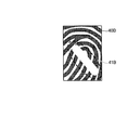
- Reference numeral 40A shown in FIG. 4A indicates a fingerprint image without a low quality region.
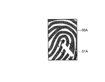
- Reference numeral 40B shown in FIG. 4B indicates a fingerprint image in which a flaw is shown.
- FIG. 4C indicates a fingerprint image in which water droplets are reflected.
- symbol 40D shown to FIG. 4D shows the fingerprint image in which the rough skin was reflected.
- FIGS. 4A to 4D it is assumed that the fingerprints copied in the fingerprint images 40A to 40D are the fingerprints of the same user.
- the fingerprint image 40A has no low quality area on the image, so the valley line 41A appears whiter than the ridge 42A, and the ridge line 42A appears blacker than the valley line 41A.
- the valley line 41A, the ridge 42A, and the boundary between them are clearly shown.
- the first narrowed-down data is created from the fingerprint image 40A, the first narrowed-down data from the fingerprint image having the low-quality area as in the fingerprint images 40B to 40D shown in FIGS. 4B to 4D. It is possible to obtain refined data with higher quality than when data is created.
- the fingerprint image 40B to the fingerprint image 40D have scratches 41B, water droplets 41C, or rough skin 41D, which are factors that make the unique features of the fingerprint unclear.
- the existing ridge is damaged until it is damaged, and the ridge is more damaged after the ridge damage than before the ridge damage. Since the direction becomes smaller, the pixel value becomes higher than the ridge.
- the fingerprint image 40C in which the water droplet 41C is shown as shown in FIG.
- the valley line is filled with the water droplet 41C, so that the pixel value is lower than before the valley line is filled with the water droplet 41C.
- the existing ridge is damaged until the rough skin 41D occurs, and the ridge is smaller than before the damage to the ridge.
- the pixel value is higher than that of the ridge. For this reason, the first creation unit 14b cannot accurately calculate how the ridge width, the ridge spacing, and the minutia are formed by the wound 41B, the water droplet 41C, and the rough skin 41D.
- the first narrowed-down data is created from the fingerprint image 40B, the fingerprint image 40C, and the fingerprint image 40D, compared to the case where the first narrowed-down data is created from the fingerprint image 40A shown in FIG. 4A. , It is possible to obtain only the narrowed-down data that increases the frequency of failing to narrow down the input person.
- the detection unit 14c can employ the following technique as a technique for extracting scratches and cracks on the fingerprint image.
- An example of such technology is “Marcelo de Almeida Oliveira, Neucimar Jeronimo Leite:“ Reconnection of Fingerprint Ridges Based on Morphological Operators and Multiscale Directional Information ”, SIBGRAPI '04, 122-129, 2004”.
- the detection unit 14c detects a block that exists at a position overlapping a region with a flaw or crack extracted from the fingerprint image by the above technique as a low-quality region of the classification “wound (crack)”.
- FIG. 5 is a diagram illustrating an example of a fingerprint image.
- FIG. 6 is a diagram showing block identification numbers.
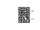
- FIG. 7 is a diagram showing a fingerprint image divided into blocks.
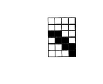
- FIG. 8 is a diagram illustrating a detection result of the low quality region.
- the number in the block shown in FIG. 6 shows the identification number of each block.
- the black fill in the block shown in FIG. 8 indicates a low quality area.
- a fingerprint image 50C divided into blocks with identification numbers 1 to 24 is obtained.
- the detection unit 14c extracts a scratch 51C from the fingerprint image 50C using the above technique, and then detects a block that exists at a position overlapping the region where the scratch 51C is present as a low quality region.
- the detection unit 14c since the area of the wound 51C overlaps the blocks of the identification numbers 14, 15, 19, 23, and 24, the identification numbers 14, 15, 19, 23, and 24 are detected by the detection unit 14c. It is detected as a low-quality area of the classification “scratch (crack)”.
- the detection unit 14c calculates the unclearness of each block from the fingerprint image using a statistical method or a frequency analysis method.
- a statistical method there is a method of smoothing the direction of a local ridge and then calculating a difference in the direction of the ridge after smoothing as the unclearness.
- the frequency analysis method the maximum power spectrum value or the kurtosis of the energy distribution of each frequency component is obtained after transforming the fingerprint image from the spatial domain to the frequency domain using Fast Fourier Transform.
- a method of calculating as unclearness may be used.
- the “blurredness” calculated in this way is an index representing that the higher the degree, the higher the possibility that the continuity of the ridge and valley line patterns is locally interrupted.
- the detection unit 14c performs a threshold determination of an average pixel value obtained by averaging the pixel values in the block with respect to a block whose blurring degree is a predetermined value or more among blocks in which the blurring degree is calculated from the fingerprint image.
- the detection unit 14c performs a threshold determination of an average pixel value obtained by averaging the pixel values in the block with respect to a block whose blurring degree is a predetermined value or more among blocks in which the blurring degree is calculated from the fingerprint image.
- the detection unit 14c detects a low quality region of the classification “water droplet” by determining whether or not the average pixel value in the block is equal to or less than the non-valley threshold. That is, as shown in FIG. 4C, when the valley line is filled with “water droplets”, the pixel value of that portion is lower than the original valley line. Therefore, when the average pixel value in the block is equal to or less than a threshold that can be estimated not to be a valley line, it can be estimated that the block is a low quality region of the classification “water droplets”. Therefore, the detection unit 14c detects a block whose average pixel value in the block is equal to or less than the non-valley threshold as a low quality region of the classification “water droplet”.
- the detection unit 14c detects a low-quality region of the classification “rough skin” by determining whether or not the average pixel value in the block is equal to or greater than the non-ridge threshold. That is, as shown in FIG. 4D, when the ridge is damaged due to “rough skin”, the ridge of the ridge becomes smaller than the original, so that the pixel value of that portion becomes higher than the original ridge. . Therefore, when the average pixel value in the block is equal to or higher than a threshold that can be estimated as not being a ridge, it can be estimated that the block is a low quality region of the classification “rough skin”. Therefore, the detection unit 14c detects a block whose average pixel value in the block is equal to or greater than the non-ridge threshold as a low quality region of the classification “rough skin”.
- the second creation unit 14d is a processing unit that creates second narrowed data related to the low quality area.
- the second narrowed data created by the second creating unit 14d is referred to as “second input narrowed data”, and the second narrowed data registered in the authentication server 30 is described. This may be described as “second registered narrowing data”.
- the second creating unit 14d includes an identification number of a block that forms a low-quality area detected by the detecting unit 14c, and reference information used when the block is divided by the dividing unit 14a.
- the second narrowed-down data is created for each cause classification.
- the second creation unit 14 d transmits the second narrowed data created for each occurrence factor classification to the authentication server 30.
- the second narrowed-down data of the classification “scratch (crack)” is corrected when the low quality region is corrected by the correction unit 14e described later.
- the second narrowed data is re-created using the corrected low quality area.
- the reason why the reference information is included in the second narrowed-down data is to align the block included in the second narrowed-down data and the block included in the second registered narrowed-down data. It is.
- the reference information there is an identification number of a block having a singular point such as a center of a fingerprint swirl or a triangle.
- the case where the identification number of the block forming the low quality area is set as the second narrowed data is exemplified, but it is not always necessary to create the position information of the low quality area for each block.
- the second creating unit 14d may use the pixel position on the fingerprint image in the low quality region of the classification “scratch (crack)”, the classification “water droplet”, and the classification “rough skin” as the second narrowed data.
- the correction unit 14e is a processing unit that corrects the low quality area detected by the detection unit 14c.
- a low quality region in which the classification of the cause of occurrence is “scratch (crack)” is corrected.
- Such a scratch or crack expands or contracts according to the magnitude of the force with which the user presses the finger bar against the fingerprint sensor 12, that is, the size of the scratch or crack on the fingerprint image read by the fingerprint sensor 12. Therefore, if the force with which the user presses the finger against the fingerprint sensor 12 is different, the size of the low-quality area is different even if the second input narrowed data and the second registered narrowed data of the same user. Things can happen.
- the width of the valley line becomes narrower.
- the weaker the force the user presses against the fingerprint sensor 12 the smaller the ridge bends, and the wider the valley line.
- the force with which the finger is pressed against the fingerprint sensor 12 is stronger as the width of the valley line is narrower, and the scratches and cracks are reduced as compared with the case where an appropriate force is applied when the fingerprint sensor 12 is used. It can be said.
- the wider the valley line, the weaker the force with which the finger is pressed against the fingerprint sensor 12, and the scratches and cracks are longer than when a proper force is applied when using the fingerprint sensor 12. I can say that.
- the correction unit 14e has a distance between the ridges detected from the fingerprint image, that is, the width of the valley line that is assumed to have an appropriate force applied when using the fingerprint sensor 12. It is determined whether or not it is within an appropriate range.
- the correction unit 14e determines whether the distance between ridges detected from a plurality of locations on the fingerprint image, that is, whether the average value WAV of the valley line is within the appropriate range of the valley line width. That is, it is determined whether or not “L 1 ⁇ W AV ⁇ L 2 ”.
- the average value WAV of the valley line width is smaller than the lower limit L 1 of the appropriate range of the valley line width, for example, 0.1 mm, an appropriate force was applied in using the fingerprint sensor 12. It is estimated that the scratches and cracks are shrinking compared to the case.
- the lower limit L 1 of the appropriate range is suitably set depending on the average value of the width of the valley line of the human fingerprint, and whether the reading method of the slide type or the stamp type is adopted for the fingerprint sensor 12. can do.
- the correction unit 14e performs correction for enlarging the low quality region when it is determined that the low quality region of the classification “scratch (crack)” detected by the detection unit 14c is contracted.
- the correction unit 14e calculates a minor axis orthogonal to the major axis of the low quality region of the classification “scratch (crack)” and then the width in the minor axis direction of the low quality distribution of the classification “scratch (crack)”.
- the low-quality area is expanded so that becomes a predetermined magnification, for example, approximately twice.
- the enlargement ratio of the low quality region may be set higher as the degree of the average value of the width of the valley line detected from a plurality of locations on the fingerprint image is lower than the lower limit value of the appropriate range of the width of the valley line. it can.
- FIG. 9 is a diagram illustrating an example of a fingerprint image.
- FIG. 10 is a diagram illustrating a detection result of the low quality region.
- FIG. 11 is a diagram showing a low quality region after correction. Black fills in the blocks shown in FIGS. 10 and 11 indicate low quality areas.
- the average value W AV of the width of the valley line is smaller than the lower limit L 1 of the proper range of the width of the valley line.
- the blocks of the identification numbers 10, 15 and 20 existing at positions overlapping the area where the scratch 61A exists are classified into “scratches (cracks)”.
- the correction unit 14e calculates a minor axis 63A that is orthogonal to the major axis 62 in the low-quality region of the classification “scratches (cracks)”. Then, as shown in FIG.
- the correction unit 14e includes blocks of identification numbers 9, 14, 19 and 24 located in the same direction as the minor axis 63A in the low quality region formed by the identification numbers 10, 15 and 20. Furthermore, correction of the low quality area to be added is performed. As a result, the low-quality areas after correction are identification numbers 9, 10, 14, 15, 19, 20, and 24.
- the average value W AV of the width of the valley line is larger than the upper limit value L 2 for example 0.3mm proper range of the width of the valley line, and if the proper force is applied when using the fingerprint sensor 12 In comparison, it is estimated that scratches and cracks are growing.
- the upper limit L 2 of the proper range the average value of the width of the valley line of a human fingerprint, more suitably set depending on the one of the scanning method of the slide or stamp type is employed in the fingerprint sensor 12 can do.
- the correction unit 14e executes correction for reducing the low quality region of the classification “scratch (crack)” detected by the detection unit 14c.
- the correction unit 14e calculates a minor axis orthogonal to the major axis of the low quality region of the classification “scratch (crack)” and then the width in the minor axis direction of the low quality distribution of the classification “scratch (crack)”.
- the low quality region is expanded so that becomes a predetermined multiple, for example, about 2/3.
- the reduction rate of the low quality region may be set higher as the degree of the average value of the valley line widths detected from a plurality of locations on the fingerprint image exceeds the upper limit value of the appropriate range of the valley line widths is increased. it can.
- FIG. 12 is a diagram illustrating an example of a fingerprint image.
- FIG. 13 is a diagram illustrating a detection result of the low quality region.
- FIG. 14 is a diagram showing a low quality region after correction. The black fill in the blocks shown in FIGS. 13 and 14 indicates a low quality area.
- the average value W AV of the width of the valley line is assumed larger than the upper limit value L 2 of the proper range of the width of the valley line.
- the identification numbers 9, 10, 13, 14, 15, 18, 19, 20 existing at the position overlapping the area where the scratch 61B exists. , 23 and 24 are detected as low quality areas of the classification “scratches (cracks)”.
- the correction unit 14e calculates the short axis 63B passing through the center of the long axis 62B in the low quality region of the classification “scratch (crack)”.
- amendment part 14e is the same direction as the short axis 63B from the low quality area
- the low-quality area correction is performed to reduce the blocks of the identification numbers 13, 18 and 23 located at.
- the low-quality areas after correction are identification numbers 9, 10, 14, 15, 19, 20, and 24.
- the second narrowed-down data including the identification number of the block forming the low quality area corrected by the correction unit 14e and the reference information used when dividing the block is obtained. It is recreated by the second creation unit 14d. If the average value WAV of the valley line width is within the appropriate range of the valley line width, that is, “L 1 ⁇ WAV ⁇ L 2 ”, correction of the low quality region by the correction unit 14e is performed. Instead, the second narrowed data created by the second creation unit 14 d is transmitted to the authentication server 30.
- the processing executed by the correcting unit 14e is not limited to this.
- the correction unit 14e expands or reduces the low quality region after dividing the block into smaller blocks than the blocks divided by the dividing unit 14a in order to realize expansion and reduction of the low quality region in a finer unit. It is good as well.
- the block divided by the dividing unit 14a can be further divided.
- the OS execution unit 15 is a processing unit that controls execution of an OS that is basic software for managing the entire computer system.
- the OS execution unit 15 executes processing related to logon and logoff. For example, if the authentication result received from the authentication server 30 is successful, the OS execution unit 15 permits the user to log in to the terminal device 10. That is, the OS execution unit 15 logs in the user by automatically inputting an account and a password.
- the OS execution unit 15 prohibits the user from logging in to the terminal device 10.
- the OS execution unit 15 may output a notification that prompts the user to input the fingerprint image again to a display unit or a voice output unit (not shown), and has no authority to use the terminal device 10. You may output a warning to the display part or audio
- the OS execution unit 15 may lock the operation of the terminal device 10.
- the fingerprint data creation unit 13 the narrowed data creation unit 14, and the OS execution unit 15.
- a part of the functional unit included in the narrowed data creation unit 14 may be another integrated circuit or an electronic circuit.
- an ASIC Application Specific Integrated Circuit
- CPU Central Processing Unit
- MPU Micro Processing Unit
- the authentication server 30 includes a communication I / F unit 31, a storage unit 32, a first calculation unit 33, a second calculation unit 34, a narrowing unit 35, and an authentication unit 36. And a registration unit 37.
- the authentication server 30 has functions of various functional units included in a known server device, such as various input devices and audio output devices, in addition to the functional units illustrated in FIG.
- the communication I / F unit 31 is an interface for performing communication control with another device, for example, the terminal device 10.
- the communication I / F unit 31 receives the input fingerprint data, the first input narrowed data, and the second input narrowed data from the terminal device 10, and receives the authentication result of the input fingerprint data as the terminal device 10. Or send to.
- a network interface card such as a LAN card or a modem can be employed.
- the storage unit 32 is a storage unit that stores input fingerprint data, first narrowed data, and second narrowed data in association with each other.
- the storage unit 32 is referred to by a first calculation unit 33 to be described later in order to calculate a first narrowing similarity between the first input narrowed data and the first registered narrowed data. Is done.
- the storage unit 32 uses a second calculating unit 34 to be described later. Referenced.
- the storage unit 32 is referred to by a below-described narrowing unit 35 to narrow down registered fingerprint data to be collated with input fingerprint data.
- the storage unit 32 is referred to by an authentication unit 36 described later in order to collate input fingerprint data and registered fingerprint data.
- the storage unit 32 stores the second narrowed-down data input together with the input fingerprint data successfully biometrically authenticated by the authentication unit 36 described later, and the registered fingerprint data referred to when biometric authentication is successful.
- a registration unit 37 In order to register in association with each other, it is referred to by a registration unit 37 described later.
- the “fingerprint data” mentioned here is registered fingerprint data registered in advance in the authentication server 30 and is suitable for an arbitrary authentication method such as a minutia method, a pattern matching method, a frequency analysis method and the like adopted by the authentication unit 36 described later. Fingerprint data is registered in advance.
- the “first narrowed data” is first registered narrowed data registered in the authentication server 30 in advance, and the width of the ridge, the interval between the ridges, the number of minutiae, and the like are associated with each block.
- the “second narrowed data” is second registered narrowed data registered in advance in the authentication server 30 and includes a block identification number and a block reference information forming a low quality area. It is data.
- a semiconductor memory element or a storage device can be adopted as the storage unit 32.
- the semiconductor memory element include VRAM (Video Random Access Memory), RAM (Random Access Memory), and flash memory.
- the storage device include storage devices such as a hard disk and an optical disk.
- the first calculation unit 33 is a processing unit that calculates the first narrowing similarity from the first input narrowed data and the first registered narrowed data.
- the first calculation unit 33 uses the first input narrowing data and the first input data for a block in which both the input fingerprint data and the registered fingerprint data form a region that is not a low-quality region.
- a first narrowing similarity is calculated from the registered narrowing data.
- a region other than the low quality region, that is, a high quality region where the unique features of the fingerprint are clear on the fingerprint image may be described as a “high quality region”.
- the first calculation unit 33 refers to the mutual reference information of the second input narrowed data and the second registered narrowed data, and aligns both blocks. Then, the first calculation unit 33 calculates a set of blocks having identification numbers other than the identification numbers of the blocks forming the high quality region, that is, the low quality region, for the input fingerprint data. Further, the first calculation unit 33 calculates a high quality region for the registered fingerprint data. Subsequently, the first calculation unit 33 calculates an area where the high quality areas of the input fingerprint data and the registered fingerprint data are common. After that, the first calculation unit 33 targets the area where the high quality areas of the input fingerprint data and the registered fingerprint data are common, and the first input narrowed data and the first registered narrowed data in the area. A first narrowing similarity is calculated by comparison. Note that the first calculation unit 33 repeatedly calculates the first narrowing similarity for each occurrence factor classification, and calculates the first narrowing similarity between all the first registered narrowing data. Repeat until it is calculated.
- the first calculation unit 33 can employ the above equation (1).
- “I” in the above formula (1) indicates input fingerprint data.
- “T” in the above formula (1) indicates registered fingerprint data.
- “S (I, T)” in the above equation (1) indicates the first narrowing similarity for each classification of the input fingerprint data I and the registered fingerprint data T.
- “U” in the above formula (1) indicates a set of blocks in which both the input fingerprint data I and the registered fingerprint data T are in common and correspond to the high quality region.
- S ⁇ (I, T)” in the above equation (1) indicates the similarity between the first input narrowed data in the block ⁇ and the first input narrowed data of the registered fingerprint data T.
- the second calculation unit 34 is a processing unit that calculates the second narrowing similarity from the second input narrowed data and the second registered narrowed data.
- the second calculation unit 34 refers to the mutual reference information of the second input narrowed data and the second registered narrowed data, and aligns both blocks. Then, the second calculation unit 34 calculates the second narrowing similarity using the following equation (2).
- “I” in the above equation (2) indicates input fingerprint data.
- “T” in the above equation (2) indicates registered fingerprint data.
- “C 1 (I, T)” in the above formula (2) indicates a correlation value of a low quality region regarding the classification “scratch (crack)” between the input fingerprint data I and the registered fingerprint data T.
- “N (I, T)” indicates the number of blocks that form a low quality region of the classification “scratches (cracks)” of the input fingerprint data I and the registered fingerprint data T.
- “N (I)” in the above formula (2) indicates the number of blocks that form a low-quality area of the classification “scratches (cracks)” of the input fingerprint data I.
- “N (T)” indicates the number of blocks that form a low quality region of the classification “scratch (crack)” of the registered fingerprint data T.
- the second calculation unit 34 increases the second narrowing similarity as the blocks forming the low quality region are shared between the second input narrowed data and the second registered narrowed data. calculate. For this reason, in the 2nd calculation part 34, if the crack and crack of the same shape exist in the same position between 2nd input narrowing data and 2nd registration narrowing data, 2nd narrowing similarity is made high. The second narrowing similarity can be calculated low even if scratches of different shapes are in the same position. Therefore, from a single viewpoint, it is possible to effectively use information having a low value in which a characteristic unique to a fingerprint is unclear on a fingerprint image for narrowing down.
- the second calculation unit 34 determines that the registered fingerprint data is within a predetermined period from the previous authentication success or fingerprint data registration. Determine if there is. Such a period is preferably within 2 weeks to 1 month, which is an approximate period during which the skin is replaced. Then, the second calculation unit 34 calculates the second narrowing similarity when the registered fingerprint data is within a predetermined period from the previous successful authentication or fingerprint data registration.
- the second calculation unit 34 refers to the mutual reference information of the second input narrowed data and the second registered narrowed data, and aligns both blocks. Then, the second calculation unit 34 calculates the second narrowing similarity using the following equation (3).
- “I” in the above equation (3) indicates input fingerprint data.
- “T” in the above equation (3) indicates registered fingerprint data.
- C 2 (I, T)” in the above equation (3) indicates a correlation value of a low quality region regarding the classification “skin roughness” between the input fingerprint data I and the registered fingerprint data T.
- “N (I, T)” in the above equation (3) indicates the number of blocks that form a low quality region of the classification “rough skin” of the input fingerprint data I and the registered fingerprint data T.
- “N (I)” in the above formula (3) indicates the number of blocks that form a low quality region of the classification “rough skin” of the input fingerprint data I.
- “N (T)” in the above formula (3) indicates the number of blocks that form a low quality region of the classification “rough skin” of the registered fingerprint data T.
- the narrowing-down unit 35 is a processing unit that narrows down registered fingerprint data to be collated with input fingerprint data among the registered fingerprint data stored in the storage unit 32.
- the narrowing unit 35 adds the first narrowing similarity calculated by the first calculating unit 33 and the second narrowing similarity calculated by the second calculating unit 34.
- the total similarity that reflects the narrowing similarity between the high quality region and the low quality region is calculated.
- the narrowing unit 35 narrows down the registered fingerprint data corresponding to the registered narrowed data whose total similarity is equal to or greater than a predetermined threshold.
- the narrowing unit 35 can execute arbitrary statistical processing as well as addition when calculating the total similarity.
- the authentication unit 36 is a processing unit that performs authentication by collating the registered fingerprint data narrowed down by the narrowing-down unit 35 and the input fingerprint data. As an example, the authentication unit 36 compares the registered fingerprint data narrowed down by the narrowing-down unit 35 with the input fingerprint data, thereby calculating a matching score of both data. And the authentication part 36 determines whether the largest collation score among the collation scores calculated previously is more than a predetermined threshold value.
- the authentication unit 36 determines that fingerprint authentication has succeeded between the registered fingerprint data having the maximum collation score and the input fingerprint data. Further, when the maximum collation score is less than the threshold, the authentication unit 36 collates the registered fingerprint data other than the registered fingerprint data narrowed down by the narrowing unit 35 with the input fingerprint data, thereby obtaining both data. The collation score of is calculated. Then, the authentication unit 36 determines that the authentication of the input fingerprint data has failed when the maximum matching score is less than the threshold value. On the other hand, if the maximum collation score is equal to or greater than the threshold, the authentication unit 36 determines that fingerprint authentication has succeeded between the registered fingerprint data having the maximum collation score and the input fingerprint data. Thereafter, the authentication unit 36 transmits the authentication result to the terminal device 10. Note that the authentication unit 36 can employ an arbitrary authentication method such as a minutia method, a pattern matching method, or a frequency analysis method.
- the registration unit 37 registers the second narrowed-down data input together with the input fingerprint data successfully biometrically authenticated by the authentication unit 36 and the registered fingerprint data referred to when biometric authentication is successful in the storage unit 32 in association with each other. Is a processing unit.
- the registration unit 37 successfully authenticates between the registered fingerprint data narrowed down by the narrowing-down unit 36 and the input fingerprint data, or the registered fingerprint data other than the registered fingerprint data narrowed down by the narrowing-down unit 35 If the authentication is successful between the input fingerprint data and the input fingerprint data, the process is started. At this time, if the second narrowed data is already registered in the storage unit 32 in association with the registered fingerprint data, the registration unit 37 receives the second fingerprint input together with the input fingerprint data successfully authenticated this time. Overwrite and register the refined data. The registration unit 37 overwrites and registers the second input narrowing data for each of the classifications “scratches (cracks)”, “skin roughness”, and “water droplets”.
- the registration unit 37 registers or overwrites not only the second input narrowed data but also the first input narrowed data. At this time, if the first registered narrowed-down data is overwritten with the new first input narrowed-down data, the information is overwritten up to the low-quality area, so the quality of the first registered narrowed-down data deteriorates. There is also a case where it ends. Therefore, the registration unit 37 registers or overwrites the first input narrowed-down data only in the high quality region for each classification of the cause of occurrence calculated together with the first narrowing similarity by the first calculating unit 33. To do.
- the first calculation unit 33 can be employed for the first calculation unit 33, the second calculation unit 34, the narrowing unit 35, the authentication unit 36, and the registration unit 37.
- an ASIC can be given as an integrated circuit.
- the electronic circuit include a CPU and an MPU.
- FIG. 15 is a flowchart illustrating a login process procedure according to the first embodiment. This login process starts when the fingerprint image is read by the fingerprint sensor 12 of the terminal device 10 in a state where the terminal device 10 is started.
- the fingerprint data creation unit 13 creates fingerprint data used for fingerprint authentication from the fingerprint image (step S101). Then, the dividing unit 14a divides the fingerprint image into blocks of a predetermined size (Step S102).
- the first creation unit 14b creates first narrowed-down data related to features unique to fingerprints using the fingerprint image divided into blocks by the division unit 14a (step S103).
- the detection unit 14c detects a low quality region from the fingerprint image divided into blocks by the dividing unit 14a (step S104).
- the second creation unit 14d creates second narrowed data related to the low quality region (step S105).
- the correction unit 14e determines whether or not the width of the valley line detected from the fingerprint image is within an appropriate range of the width of the valley line that is assumed to have an appropriate force applied when the fingerprint sensor 12 is used. Is determined (step S106). If the valley line width is within the appropriate range (Yes at Step S106), the processing of Steps S107 and S108 is skipped, and the process proceeds to Step S109.
- the correction unit 14e performs correction for enlarging or reducing the low quality region detected by the detection unit 14c (Step S107). . Thereafter, the second creation unit 14d re-creates second narrowed-down data including the identification number of the block forming the low quality area corrected by the correction unit 14e and the reference information used when the block is divided. (Step S108).
- the communication I / F unit 11 transmits the input fingerprint data, the first input narrowed data, and the second input narrowed data to the authentication server 30 (step S109). Thereafter, the communication I / F unit 11 receives an authentication result from the authentication server 30 (step S110).
- Step S111 the OS execution unit 15 permits the user to log in to the terminal device 10 (Step S112), and ends the process. If the authentication result is unsuccessful (No at step S111), the process ends without permitting login.
- processing in steps S103 and S104 shown in FIG. 15 and the processing in steps S105 and S108 shown in FIG. 15 do not have to be executed in the order shown in the drawing, and are executed by switching their order. Can do.
- FIG. 16 is a flowchart illustrating a procedure of biometric authentication processing according to the first embodiment.
- This biometric authentication process is a process that is repeatedly executed as long as the power of the authentication server 30 is ON.
- the input fingerprint data, the first input narrowed data, and the second input narrowed data are received from the terminal device 10. Processing starts when received.
- the first calculation unit 33 calculates the first narrowing similarity from the first input narrowing data and the first registered narrowing data (step S301). Then, the second calculation unit 34 calculates a second narrowing similarity from the second input narrowed data and the second registered narrowed data (step S302).
- the authentication unit 36 collates the registered fingerprint data narrowed down by the narrowing down unit 35 with the input fingerprint data (step S305). At this time, when the authentication fails between the registered fingerprint data narrowed down by the narrowing-down unit 35 and the input fingerprint data (Yes in step S306), the authentication unit 36 uses the registered fingerprint narrowed down by the narrowing-down unit 35 The registered fingerprint data other than the data is collated with the input fingerprint data (step S307).
- the registration unit 37 performs the following processing Execute. That is, the registration unit 37 associates the second narrowed-down data input together with the input fingerprint data successfully succeeded in the second biometric authentication without entering the narrow-down and the registered fingerprint data referred to when the biometric authentication is successful. To the storage unit 32 (step S309). Thereafter, the authentication unit 36 transmits the authentication result to the terminal device 10 (step S310), and ends the process.
- the authentication unit 36 sends the authentication result to the terminal device 10. (Step S310), and the process ends.
- the registration unit 37 executes the following process. That is, the registration unit 37 associates the second narrowed-down data input together with the input fingerprint data successfully biometrically authenticated by the authentication unit 36 with the registered fingerprint data referred to when biometric authentication is successful, and the storage unit 32. (Step S309). Thereafter, the authentication unit 36 transmits the authentication result to the terminal device 10 (step S310), and ends the process.
- steps S301 and S302 shown in FIG. 16 need not be executed in the order shown in the drawing, and can be executed by switching the order of each other.
- the biometric authentication system 1 according to the present embodiment has a unique fingerprint on a fingerprint image due to scratches or rough skin when authentication is successful even if the user's fingerprint changes due to scratches or rough skin.
- the position information of the area where the feature is unclear is added to the registered fingerprint data as narrowed-down data.
- registered fingerprint data having position information similar to the position information of the region is narrowed down. . Therefore, in the biometric authentication system 1 according to the present embodiment, the probability that the registered fingerprint data of the user who has input the fingerprint is included in the narrowed-down result is increased.
- the biometric authentication system 1 it is possible to stabilize the accuracy of narrowing down. Furthermore, in the biometric authentication system 1 according to the present embodiment, since the probability that the registered fingerprint data of the user himself / herself is included in the narrowing-down result increases, it is possible to prevent the authentication from failing in conjunction with the narrowing-down failure, The authentication time from when the fingerprint is input to when the authentication result is output can be shortened.
- the biometric authentication system 1 according to the present embodiment narrows down the registered fingerprint data having position information similar to the position information of the low quality area detected from the input fingerprint image among the registered fingerprint data. For this reason, in the biometric authentication system 1 according to the present embodiment, it is possible to effectively use information having a low value that the characteristic unique to the fingerprint is unclear on the fingerprint image for narrowing down.
- the biometric authentication system 1 has position information similar to the position information of the low quality area detected from the input fingerprint image in the registered fingerprint data, and is in an area other than the low quality area.
- the registered fingerprint data having a feature amount similar to the first input narrowing data is narrowed down.
- the biometric authentication system 1 corrects the position information of the low quality region according to the input state of the input fingerprint data. Furthermore, the biometric authentication system 1 according to the present embodiment uses the registered fingerprint to be compared with the input fingerprint data among the registered fingerprint data based on the corrected low-quality area position information and the stored low-quality area position information. Narrow down the data. For this reason, in the biometric authentication system 1 which concerns on a present Example, it can prevent that dispersion
- the processing executed by the correction unit 14e is not limited to this.
- the average value W AV of the width of the valley line is smaller than the lower limit L 1 of the proper range of the width of the valley line
- the correction unit 14e is the low quality area by the expansion of the morphological operations
- the number of blocks can be expanded.
- the average value W AV of the width of the valley line is larger than the upper limit value L 2 of the proper range of the width of the valley line
- the correction unit 14e is the low quality region by contraction of the morphological operations The number of blocks can be reduced.
- the disclosed system is not limited to this, and can be similarly applied to other biometric authentication such as palm prints and veins.
- biometric authentication such as palm prints and veins.
- vein authentication there is a similar problem that there is a temporary change in biological information due to a thrombus in the vein, and therefore the disclosed system can be similarly applied.
- each component of each illustrated apparatus does not necessarily need to be physically configured as illustrated.
- the specific form of distribution / integration of each device is not limited to that shown in the figure, and all or a part thereof may be functionally or physically distributed or arbitrarily distributed in arbitrary units according to various loads or usage conditions.
- the first calculation unit 33, the second calculation unit 34, the narrowing unit 35, the authentication unit 36, or the registration unit 37 may be connected as an external device of the authentication server 30 via a network.
- the first calculation unit 33, the second calculation unit 34, the narrowing unit 35, the authentication unit 36, or the registration unit 37 is provided in a separate device, and is connected to the network to cooperate.
- part or all of the functional units included in the fingerprint data creation unit 13, the narrowed data creation unit 14, and the narrowed data creation unit 14 may be connected as an external device of the terminal device 10 via a network.
- another device has a part or all of the functional units included in the fingerprint data creation unit 13, the narrowed data creation unit 14, and the narrowed data creation unit 14, and is connected to the network to cooperate. You may make it implement
- Biometric authentication program The various processes described in the above embodiments can be realized by executing a prepared program on a computer such as a personal computer or a workstation.
- a computer such as a personal computer or a workstation.
- an example of a computer that executes a biometric authentication program having the same function as that of the above embodiment will be described with reference to FIG.
- FIG. 17 is a schematic diagram illustrating an example of a computer that executes a biometric authentication program according to the first and second embodiments.
- the computer 100 includes an operation unit 110a, a speaker 110b, a camera 110c, a display 120, and a communication unit 130. Further, the computer 100 includes a CPU 150, a ROM 160, an HDD 170, and a RAM 180. These units 110 to 180 are connected via a bus 140.
- the HDD 170 includes a first calculation unit 33, a second calculation unit 34, a narrowing unit 35, an authentication unit 36, and a registration unit 37 described in the first embodiment.
- a biometric authentication program 170a that exhibits the same function is stored in advance.
- the biometric authentication program 170a is integrated as appropriate as with each component of the first calculation unit 33, the second calculation unit 34, the narrowing unit 35, the authentication unit 36, and the registration unit 37 shown in FIG. Or you may isolate
- all data stored in the HDD 170 need not always be stored in the HDD 170, and only data necessary for processing may be stored in the HDD 170.
- the CPU 150 reads the biometric authentication program 170 a from the HDD 170 and expands it in the RAM 180. Accordingly, as shown in FIG. 17, the biometric authentication program 170a functions as a biometric authentication process 180a.
- the biometric authentication process 180a expands various data read from the HDD 170 in an area allocated to itself on the RAM 180 as appropriate, and executes various processes based on the expanded data.
- the biometric authentication process 180a is performed by the first calculation unit 33, the second calculation unit 34, the narrowing unit 35, the authentication unit 36, and the registration unit 37 illustrated in FIG.
- the process shown in FIG. 16 is included.
- each processing unit virtually realized on the CPU 150 does not always require that all processing units operate on the CPU 150, and only a processing unit necessary for the processing needs to be virtually realized.
- the biometric authentication program 170a is not necessarily stored in the HDD 170 or the ROM 160 from the beginning.
- each program is stored in a “portable physical medium” such as a flexible disk inserted into the computer 100, so-called FD, CD-ROM, DVD disk, magneto-optical disk, or IC card. Then, the computer 100 may acquire and execute each program from these portable physical media.
- each program is stored in another computer or server device connected to the computer 100 via a public line, the Internet, a LAN, a WAN, etc., and the computer 100 acquires and executes each program from these. It may be.
Landscapes
- Engineering & Computer Science (AREA)
- Theoretical Computer Science (AREA)
- Physics & Mathematics (AREA)
- General Physics & Mathematics (AREA)
- Multimedia (AREA)
- Quality & Reliability (AREA)
- Computer Security & Cryptography (AREA)
- Computer Vision & Pattern Recognition (AREA)
- Computer Hardware Design (AREA)
- Software Systems (AREA)
- General Engineering & Computer Science (AREA)
- Collating Specific Patterns (AREA)
Abstract
生体認証システム(1)は、生体認証に成功した生体情報の画像上で生体固有の特徴領域の位置情報と、生体認証の成功時に参照された参照用の生体情報とを対応付けて記憶部に記録する。さらに、生体認証システム(1)は、入力された認証対象の生体情報の画像から生体固有の特徴領域を検出する。さらに、生体認証システム(1)は、検出結果として得られた特徴領域の位置情報と記憶部に記憶された領域の位置情報との類似度に基づいて、記憶部に記憶された参照用の生体情報のうち認証対象の生体情報と照合する参照用の生体情報を絞り込む。さらに、生体認証システム(1)は、絞込結果として得られた参照用の生体情報と認証対象の生体情報とを照合して認証する。
Description
本発明は、生体認証システム、生体認証方法及び生体認証プログラムに関する。
生体認証技術の認証方式の一例としては、「1:1認証」と「1:N認証」が挙げられる。かかる1:1認証は、利用者によって入力された生体情報と利用者の識別情報に対応付けて予め登録された生体情報とを照合することで認証する方式を指す。また、1:N認証は、利用者によって入力された生体情報と予め登録されたN人の生体情報とを照合することで認証する方式を指す。このうち、1対N認証を採用する場合には、利用者によって入力された生体データを、予め登録されているN人の生体データとの間で照合するので、生体データの登録数Nが多いほど認証結果が出力されるまでに時間がかかる。
かかる1対N認証の認証時間を短縮する技術の一例として、入力指紋と登録指紋の間で指紋の特徴量を代表する選択用パラメータを比較することによって入力指紋と照合する登録指紋を絞り込む指紋照合装置が挙げられる。この指紋照合装置では、選択用パラメータとして、全指紋領域に対する隆線領域の割合、隆線と谷線の間隔、指紋の隆線又は谷線が持つ端点あるいは分岐点の数などを照合の前に比較する。
しかしながら、上記の従来技術では、以下に説明するように、絞り込みの精度が安定しないという問題がある。
すなわち、上記の指紋照合装置は、同じ利用者であれば指紋が登録された時点と登録された指紋が認証に用いられる時点とで指紋に変化がないことを前提に絞り込みを行うものである。このため、上記の指紋照合装置では、傷や皮膚荒れなどによって生体に一時的な変化が発生した場合の絞り込みには対応できない。なぜなら、傷や皮膚荒れなどによって指紋に一時的な変化が起こった場合には、同じ利用者の指紋であっても入力指紋と登録指紋の間で比較される選択用パラメータの差が大きくなる。それゆえ、上記の指紋照合装置では、入力指紋及び登録指紋の間で選択用パラメータを比較することによって登録指紋を絞り込んだとしても、指紋を入力した利用者本人の登録指紋が入力指紋と照合する登録指紋の中に絞り込まれない場合がある。
開示の技術は、上記に鑑みてなされたものであって、絞り込みの精度を安定させることができる生体認証システム、生体認証方法及び生体認証プログラムを提供することを目的とする。
本願の開示する生体認証システムは、一つの態様において、生体認証に成功した生体情報の画像上で生体固有の特徴領域の位置情報と、前記生体認証の成功時に参照された参照用の生体情報とを対応付けて記憶部に記録する登録部を有する。前記生体認証システムは、入力された認証対象の生体情報の画像から生体固有の特徴領域を検出する検出部を有する。前記生体認証システムは、前記検出部によって検出された特徴領域の位置情報と前記記憶部に記憶された領域の位置情報とに基づいて、前記記憶部に記憶された参照用の生体情報のうち前記認証対象の生体情報と照合する参照用の生体情報を絞り込む絞込部を有する。前記生体認証システムは、前記絞込部によって絞り込まれた参照用の生体情報と前記認証対象の生体情報とを照合して認証する認証部を有する。
本願の開示する生体認証システムの一つの態様によれば、絞り込みの精度を安定させることができるという効果を奏する。
以下に、本願の開示する生体認証システム、生体認証方法及び生体認証プログラムの実施例を図面に基づいて詳細に説明する。なお、この実施例は開示の技術を限定するものではない。そして、各実施例は、処理内容を矛盾させない範囲で適宜組み合わせることが可能である。
[システム構成]
まず、本実施例に係る生体認証システムの構成について説明する。図1は、実施例1に係る生体認証システムの構成を示す図である。図1に示す生体認証システム1には、端末装置10A~端末装置10Cと、認証サーバ30とが収容される。なお、図1の例では、認証サーバ30が、端末装置10A~端末装置10Cのいずれかで入力された利用者の指紋データと、予め登録された複数の指紋データとの間で1:Nの指紋認証を実行する場合を想定する。
まず、本実施例に係る生体認証システムの構成について説明する。図1は、実施例1に係る生体認証システムの構成を示す図である。図1に示す生体認証システム1には、端末装置10A~端末装置10Cと、認証サーバ30とが収容される。なお、図1の例では、認証サーバ30が、端末装置10A~端末装置10Cのいずれかで入力された利用者の指紋データと、予め登録された複数の指紋データとの間で1:Nの指紋認証を実行する場合を想定する。
これら端末装置10A~端末装置10Cと認証サーバ30との間は、ネットワーク3を介して通信可能に接続される。なお、ネットワーク3の一態様としては、インターネット(Internet)、LAN(Local Area Network)やVPN(Virtual Private Network)などの通信網が採用される。
図1の例では、3つの端末装置、1つの認証サーバをそれぞれ図示したが、開示のシステムは図示の構成に限定されない。すなわち、生体認証システム1は、少なくとも端末装置及び認証サーバが1つずつ収容されていればよく、任意の数の端末装置及び認証サーバを収容できる。なお、以下では、端末装置10A~端末装置10Cの各装置を区別なく説明する場合には、「端末装置10」と表現する場合がある。
端末装置10は、利用者によって利用される情報処理装置である。かかる端末装置10の一態様としては、パーソナルコンピュータ(PC:Personal Computer)を始めとする固定端末の他、携帯電話機、PHS(Personal Handyphone System)やPDA(Personal Digital Assistant)、スマートフォンなどの移動体端末も採用できる。なお、ここでは、一例として、利用者がPCにログインする場合を想定して以下の説明を行う。
かかる端末装置10は、自装置へのログインに際して、アカウント及びパスワードに代えて利用者の指紋画像の入力を受け付け、後述の認証サーバ30に実行させた指紋認証の結果により、端末装置10に対する利用者のログインを許可または禁止する。
これを説明すると、端末装置10は、図示しない指紋センサによって指紋が読み取られた画像から、後述の認証サーバ30によって指紋認証が実行される場合に使用させる指紋データを作成する。なお、以下では、端末装置10の指紋センサによって指紋が読み取られた画像のことを「指紋画像」と記載する場合がある。さらに、以下では、指紋画像から作成された指紋データのことを「入力指紋データ」と記載するとともに、後述の認証サーバ30に予め登録されている指紋データのことを「登録指紋データ」と記載する場合がある。
さらに、端末装置10は、指紋センサによって読み取られた指紋画像から、後述の認証サーバ30によって入力指紋データと照合する登録指紋データが絞り込まれる場合に使用させる絞込データを作成する。なお、以下では、指紋画像から作成された絞込データのことを「入力絞込データ」と記載するとともに、後述の認証サーバ30に予め登録されている絞込データのことを「登録絞込データ」と記載する場合がある。
その上で、端末装置10は、指紋画像から作成した指紋データ及び絞込データを後述の認証サーバ30に送信する。このように、端末装置10が、指紋画像そのものではなく、指紋画像から作成した指紋データ及び絞込データをネットワーク3に送出するので、指紋という利用者の個人情報が外部に漏れるのを防止できる。なお、ここでは、端末装置10が指紋画像から指紋データ及び絞込データを作成する場合を例示するが、端末装置10が指紋画像をそのまま認証サーバ30へ送信し、認証サーバ30に指紋データ及び絞込データを作成させることとしてもかまわない。
このとき、端末装置10は、後述の認証サーバ30による認証結果が認証成功である場合には、端末装置10に対する利用者のログインを許可する。すなわち、端末装置10は、アカウント及びパスワードを自動入力することにより、利用者をログインさせる。これによって、利用者の本人認証のセキュリティをパスワード認証よりも向上させた上で、パスワードが忘却されたり、パスワードが漏洩したりするリスクを低減させる。
一方、端末装置10は、後述の認証サーバ30による認証結果が認証失敗である場合には、端末装置10に対する利用者のログインを禁止する。この場合には、端末装置10は、指紋画像を再度入力するように利用者を促す報知を出力してもよく、端末装置10の利用権限がない旨の警告を出力してもよく、また、端末装置10の操作をロックすることとしてもよい。
認証サーバ30は、指紋認証サービスを提供するサーバ装置である。かかる認証サーバ30は、端末装置10から入力指紋データ及び入力絞込データを受け付けた場合に、入力絞込データ及び登録絞込データを用いて、指紋認証に先立って入力指紋データと照合する登録指紋データを絞り込む。一例としては、認証サーバ30は、入力絞込データ及び登録絞込データから算出される絞込類似度が、登録指紋データの総数Nに対する所定の割合、例えば上位10分の1(=N/10)以内に入る登録絞込データに対応する登録指紋データを絞り込む。他の一例としては、認証サーバ30は、入力絞込データ及び登録絞込データから算出される絞込類似度が所定の閾値以上である登録絞込データに対応する登録指紋データを絞り込む。
その上で、認証サーバ30は、入力指紋データと、絞込結果として得られた登録指紋データとを照合することにより認証する。一例としては、認証サーバ30は、入力指紋データが先に絞り込まれた全ての登録指紋データと照合されるまで、入力指紋データ及び登録指紋データから算出される照合類似度が所定の閾値以上であるか否かを判定する処理を繰り返す。このとき、認証サーバ30は、少なくとも1つの登録指紋データとの間で照合類似度が閾値以上である場合には、入力指紋データの認証に成功した旨を端末装置10に応答する。一方、認証サーバ30は、全ての登録指紋データとの間で照合類似度が閾値未満である場合には、入力指紋データの認証に失敗した旨を端末装置10に応答する。
ここで、本実施例に係る生体認証システム1は、指紋認証に成功した入力指紋データに対応する指紋画像上で指紋固有の特徴が不鮮明な領域の位置情報と、指紋認証の成功時に参照された登録指紋データとを対応付けて記憶部に登録する。その後、本実施例に係る生体認証システム1は、新たに入力された入力指紋データに対する指紋画像から指紋固有の特徴が不鮮明な領域を検出する。さらに、本実施例に係る生体認証システム1は、検出結果として得られた領域の位置情報と記憶部に記憶された領域の位置情報との類似度に基づいて、記憶部に記憶された登録指紋データのうち入力指紋データと照合する登録指紋データを絞り込む。さらに、本実施例に係る生体認証システム1は、絞込結果として得られた登録指紋データと入力指紋データとを照合して認証する。
このように、本実施例に係る生体認証システム1では、利用者の指紋が傷や皮膚荒れにより変化しても、認証に成功した段階で傷や皮膚荒れによって指紋画像上で指紋固有の特徴が不鮮明になった領域の位置情報が絞込データとして登録指紋データに付加される。このため、本実施例に係る生体認証システム1では、以降の認証で傷や皮膚荒れがある指紋データが入力された場合にその領域の位置情報と類似する位置情報を持つ登録指紋データが絞り込まれる。それゆえ、本実施例に係る生体認証システム1では、指紋を入力した利用者本人の登録指紋データが絞込結果の中に含まれる蓋然性が高まる。
よって、本実施例に係る生体認証システム1によれば、絞り込みの精度を安定させることができる。さらに、本実施例に係る生体認証システム1では、利用者本人の登録指紋データが絞込結果の中に含まれる蓋然性が高まるので、絞込失敗に連動して認証が失敗することを防止でき、指紋が入力されてから認証結果が出力されるまでの認証時間も短縮できる。
[端末装置10の構成]
続いて、本実施例に係る端末装置の構成について説明する。図2は、実施例1に係る生体認証システムに含まれる各装置の構成を示すブロック図である。図2に示すように、端末装置10は、通信I/F(Interface)部11と、指紋センサ12と、指紋データ作成部13と、絞込データ作成部14と、OS(Operating System)実行部15とを有する。なお、端末装置10は、図2に示した機能部以外にも既知のPCが有する各種の機能部、例えば各種の入力デバイスや音声出力デバイスなどの機能を有するものとする。
続いて、本実施例に係る端末装置の構成について説明する。図2は、実施例1に係る生体認証システムに含まれる各装置の構成を示すブロック図である。図2に示すように、端末装置10は、通信I/F(Interface)部11と、指紋センサ12と、指紋データ作成部13と、絞込データ作成部14と、OS(Operating System)実行部15とを有する。なお、端末装置10は、図2に示した機能部以外にも既知のPCが有する各種の機能部、例えば各種の入力デバイスや音声出力デバイスなどの機能を有するものとする。
このうち、通信I/F部11は、他の装置、例えば認証サーバ30との間で通信制御を行うインタフェースである。例えば、通信I/F部11は、後述の指紋データ作成部13によって作成された指紋データや後述の絞込データ作成部14によって作成された絞込データを認証サーバ30に送信したり、また、認証サーバ30から認証結果を受信したりする。かかる通信I/F部11の一態様としては、LANカードなどのネットワークインタフェースカード(NIC:Network Interface Card)やモデムを採用できる。
指紋センサ12は、指紋を読み取るセンサである。かかる指紋センサ12の実装例としては、指紋センサ12が端末装置10に内蔵される態様を採用できる他、端末装置10にUSB(Universal Serial Bus)等で接続される態様を採用できる。また、指紋センサ12の検知方式の一例としては、静電容量式、電界検知式、光学式、感熱式、感圧式など任意の検知方式を採用できる。さらに、指紋センサ12の読取方式の一例としては、指のはら、すなわち指先の内側の中央部をスライドさせるスライド型であってもよいし、指のはらを載置させるスタンプ型であってもかまわない。
指紋データ作成部13は、指紋画像から指紋認証に用いられる指紋データを作成する処理部である。一例としては、指紋データ作成部13は、後述の認証サーバ30の認証部36によって採用されるマニューシャ方式、パターンマッチング方式や周波数解析法などの任意の認証方式に合わせて、指紋センサ12により読み取られた指紋画像から指紋データを作成する。
例えば、指紋データ作成部13は、後述の認証部36によってマニューシャ方式が採用される場合には、指紋画像の紋様に含まれる隆線の端点や分岐点などの特徴点の方向と、位置関係や特徴点相互間の相関関係とを指紋データとして作成する。また、指紋データ作成部13は、後述の認証部36によってパターンマッチング方式が採用される場合には、指紋画像が2値化または細線化された画像を指紋データとして作成する。また、指紋データ作成部13は、後述の認証部36によって周波数解析法が採用される場合には、指紋画像の紋様パターンをスライスした断面を波形と見なした場合の波形スペクトル系列を指紋データとして作成する。
絞込データ作成部14は、指紋画像から登録指紋データの絞り込みに用いられる絞込データを作成する処理部である。かかる絞込データ作成部14は、図2に示すように、分割部14aと、第1の作成部14bと、検出部14cと、第2の作成部14dと、補正部14eとを有する。
このうち、分割部14aは、指紋画像を所定のサイズのブロックに分割する処理部である。一態様としては、分割部14aは、指紋センサ12によって読み取られた指紋画像を探索することにより、指紋の基準点、例えば指紋を形成する紋様(渦)の中心である指紋中心を検出する。そして、分割部14aは、指紋画像の探索により検出した指紋中心をもとに、指紋画像のうち、以降の処理、例えば絞込データの作成などの対象とする領域を切り出した上でその領域の画像をブロック分割する。
ここで、指紋画像の切出しについて説明する。図3は、指紋画像の切出し方法を説明するため図である。図3に示すように、分割部14aは、指紋センサ12によって読み取られた指紋画像20を探索する。かかる探索によって、分割部14aは、指紋画像20から指紋を形成する紋様の中心である指紋中心21を検出する。そして、分割部14aは、指紋画像20における指紋中心21を中心または重心とする指紋画像20の切出し領域22を設定する。このとき、分割部14aは、長軸方向23が指の第一関節のしわと比較して鉛直な方向、すなわち指先方向となる長方形を切出し領域22として設定する。さらに、分割部14aは、切出し領域22の大きさを所定のブロック数に分割可能な程度の大きさに設定する。その後、分割部14aは、指紋画像20から切出し領域22を切り出すことによって切出し後の指紋画像24を抽出する。
なお、分割部14aは、後述の第1の作成部14b及び後述の第2の作成部14dから送信される基準情報、例えば指紋の基準点とする特異点の種別や切出し領域22の大きさなどにしたがって指紋画像20の切出しを行う。また、分割部14aには、認証サーバ30の記憶部32に登録された第1の絞込データ及び第2の絞込データの作成時に用いられた切出し方法と同様の切出し方法で切り出すことを予め定義しておくこともできる。
このように指紋画像の切出しを行った上で、分割部14aは、切出し後の指紋画像の各ブロックに複数の隆線の一部が含まれるように、成人の指で隆線が隣接する間隔の代表値の数倍程度の値、例えば2倍に相当する画素数を一辺の大きさとしたブロックに指紋画像を分割する。例えば、成人の指における隆線の間隔の代表値が約0.2mmであるとしたとき、分割部14aは、約0.4mmに相当する画素数を一辺としたブロックに指紋画像を分割する。なお、分割部14aは、ブロックに分割した指紋画像を後述の第1の作成部14b及び後述の検出部14cへ出力する。
なお、上記のブロックの一辺の大きさは、システムの管理者が任意に変更することができる。一例としては、学校などのように利用者の年代が特定の年代に限定できる場合には、分割部14aは、特定の年代の指における隆線の間隔の代表値をもとにブロックを構成する画素数を自動的に設定できる。
第1の作成部14bは、分割部14aによってブロックに分割された指紋画像を用いて、指紋固有の特徴に関する第1の絞込データを作成する処理部である。ここでは、第1の作成部14bによってマニューシャに関する絞込データが第1の絞込データとして作成される場合を想定して以下の説明を行う。一例としては、第1の作成部14bは、指紋画像のブロックごとにブロック内で検出された隆線の幅、ブロック内で検出された隆線の間隔、ブロック内で検出されたマニューシャの個数などを算出する。このようにして算出された隆線の幅、隆線の間隔、マニューシャの個数が第1の絞込データとして認証サーバ30へ送信される。なお、以下では、第1の作成部14bによって作成された第1の絞込データのことを「第1の入力絞込データ」と記載するとともに、認証サーバ30に登録された第1の絞込データのことを「第1の登録絞込データ」と記載する場合がある。
検出部14cは、分割部14aによってブロックに分割された指紋画像から指紋固有の特徴が不鮮明な領域を検出する処理部である。以下では、指紋画像上で指紋固有の特徴が不鮮明な領域、すなわち指紋固有の特徴が鮮明な領域よりも絞り込みを行う上で低品質な領域を「低品質領域」と記載する場合がある。
ここで、検出部14cは、指紋画像上における低品質領域を発生要因別に検出する。上記の低品質領域が発生する要因は、傷や亀裂、水滴の付着、皮膚荒れなどに分類される。ここで言う「水滴」には、汗などが含まれる。また、「皮膚荒れ」には、表皮の剥がれ、タコ、摩耗などが含まれる。図4A~図4Dは、低品質領域の分類を説明するための図である。図4Aに示す符号40Aは、低品質領域がない指紋画像を示す。図4Bに示す符号40Bは、傷が写った指紋画像を示す。図4Cに示す符号40Cは、水滴が写った指紋画像を示す。また、図4Dに示す符号40Dは、皮膚荒れが写った指紋画像を示す。なお、図4A~図4Dの例では、指紋画像40A~指紋画像40Dに写された指紋が同一の利用者の指紋であるものとする。
図4Aに示すように、指紋画像40Aには、低品質領域が画像上にないので、谷線41Aが隆線42Aに比べて白く写り、また、隆線42Aが谷線41Aに比べて黒く写り、谷線41A、隆線42A及び両者の境界が明瞭に写る。このため、指紋画像40Aから第1の絞込データが作成された場合には、図4B~図4Dに示す指紋画像40B~40Dのように、低品質領域を持つ指紋画像から第1の絞込データが作成される場合よりも高品質な絞込データを得ることができる。
図4B~図4Dに示すように、指紋画像40B~指紋画像40Dには、指紋固有の特徴が不鮮明になる要因である傷41B、水滴41Cまたは皮膚荒れ41Dが存在する。このとき、傷41Bが写った指紋画像40Bの場合には、図4Bに示すように、傷付くまでは存在した隆線が損傷して隆起が隆線の損傷前よりも隆線の損傷後の方が小さくなるので、隆線よりも画素値が高くなる。また、水滴41Cが写った指紋画像40Cの場合には、図4Cに示すように、水滴41Cによって谷線が埋まるので、谷線が水滴41Cによって埋まる前よりも画素値が低くなる。また、皮膚荒れ41Dが写った指紋画像40Dの場合には、図4Dに示すように、皮膚荒れ41Dが起こるまで存在した隆線が損傷して隆起が隆線の損傷前よりも小さくなるので、隆線よりも画素値が高くなる。このため、傷41B、水滴41C及び皮膚荒れ41Dで隆線の幅、隆線の間隔及びマニューシャがどのように形成されているかは第1の作成部14bで正確に算出できない。よって、指紋画像40B、指紋画像40C及び指紋画像40Dから第1の絞込データが作成された場合には、図4Aに示した指紋画像40Aから第1の絞込データが作成された場合よりも、入力した本人の絞り込みに失敗する頻度が高くなるような絞込データしか得ることができない。
一態様として、検出部14cは、指紋画像上における傷や亀裂を抽出する技術として、次のような技術を採用できる。かかる技術の一例としては、「Marcelo de Almeida Oliveira,Neucimar Jeronimo Leite: “Reconnection of Fingerprint Ridges Based on Morphological Operators and Multiscale Directional Information”,SIBGRAPI’04,122-129,2004」がある。検出部14cは、上記の技術によって指紋画像から抽出された傷または亀裂がある領域と重なる位置に存在するブロックを分類「傷(亀裂)」の低品質領域として検出する。
図5~図8を用いて、低品質領域の検出方法について説明する。図5は、指紋画像の一例を示す図である。図6は、ブロックの識別番号を示す図である。図7は、ブロックに分割された指紋画像を示す図である。図8は、低品質領域の検出結果を示す図である。なお、図6に示すブロック内の数字は、各ブロックの識別番号を示す。また、図8に示すブロック内の黒の塗りつぶしは、低品質領域を指す。
図5に示すように、分割部14aによって傷51Aの写った指紋画像50Aが図6に示した識別番号1~24の24個(=縦6個×横4個)のブロックに分割される。このようにして指紋画像50Aが分割された場合には、図7に示すように、識別番号1~24のブロックに分割された指紋画像50Cが得られる。そして、検出部14cは、上記の技術を用いて指紋画像50Cから傷51Cを抽出した上で傷51Cがある領域と重なる位置に存在するブロックを低品質領域として検出する。この場合には、図8に示すように、傷51Cの領域が識別番号14、15、19、23及び24のブロックと重なるので、検出部14cによって識別番号14、15、19、23及び24が分類「傷(亀裂)」の低品質領域として検出される。
他の一態様として、検出部14cは、統計手法または周波数解析法を用いて、指紋画像から各ブロックの不鮮明度を算出する。かかる統計手法の一例としては、局所的な隆線の方向を平滑化した上で平滑化後の隆線の方向の差を不鮮明度として算出する手法などが挙げられる。周波数解析法の一例としては、高速フーリエ変換(Fast Fourier Transform)を用いて、空間領域から周波数領域へと指紋画像を変換した上で最大パワースペクトルの値又は各周波数成分のエネルギー分布の尖度を不鮮明度として算出する手法などが挙げられる。このようにして算出される「不鮮明度」は、度合いが高いほど局所的に隆線や谷線のパターンの連続性が途切れている可能性が高いことを表す指標である。
その上で、検出部14cは、指紋画像から不鮮明度が算出されたブロックのうち不鮮明度が所定値以上であるブロックを対象に、ブロック内の画素値を平均した平均画素値の閾値判定を行うことによって分類「水滴」及び分類「皮膚荒れ」の低品質領域を検出する。このように、不鮮明度が所定値以上であるブロックを低品質領域の検出対象とするのは、局所的に隆線や谷線のパターンの連続性が途切れている可能性が高い領域に水滴が付着したり、皮膚荒れが起こったりしている可能性も高いからである。
例えば、検出部14cは、ブロック内の平均画素値が非谷線閾値以下であるか否かを判定することによって分類「水滴」の低品質領域を検出する。すなわち、図4Cに示したように、「水滴」によって谷線が埋まった場合には、その部分の画素値が元の谷線よりも低くなる。それゆえ、ブロック内の平均画素値が谷線ではないと推定できる程度の閾値以下である場合には、当該ブロックが分類「水滴」の低品質領域であると推定できる。よって、検出部14cは、ブロック内の平均画素値が非谷線閾値以下であるブロックを分類「水滴」の低品質領域として検出する。
これとは逆に、検出部14cは、ブロック内の平均画素値が非隆線閾値以上であるか否かを判定することによって分類「皮膚荒れ」の低品質領域を検出する。すなわち、図4Dに示したように、「皮膚荒れ」によって隆線が損傷した場合には、隆線の隆起が元よりも小さくなるので、その部分の画素値が元の隆線よりも高くなる。それゆえ、ブロック内の平均画素値が隆線ではないと推定できる程度の閾値以上である場合には、当該ブロックが分類「皮膚荒れ」の低品質領域であると推定できる。よって、検出部14cは、ブロック内の平均画素値が非隆線閾値以上であるブロックを分類「皮膚荒れ」の低品質領域として検出する。
第2の作成部14dは、低品質領域に関する第2の絞込データを作成する処理部である。以下では、第2の作成部14dによって作成された第2の絞込データのことを「第2の入力絞込データ」と記載するとともに、認証サーバ30に登録された第2の絞込データのことを「第2の登録絞込データ」と記載する場合がある。
一例としては、第2の作成部14dは、検出部14cによって検出された低品質領域を形成するブロックの識別番号と、分割部14aによってブロックが分割される際に使用された基準情報とを含む第2の絞込データを発生要因の分類別に作成する。その上で、第2の作成部14dは、発生要因の分類別に作成した第2の絞込データを認証サーバ30へ送信する。なお、発生要因の分類別に作成した第2の絞込データのうち分類「傷(亀裂)」の第2の絞込データは、後述の補正部14eによって低品質領域が補正された場合には、補正後の低品質領域を用いて第2の絞込データが再作成される。
このように、第2の絞込データに基準情報を含めるのは、第2の入力絞込データに含まれるブロックと、第2の登録絞込データに含まれるブロックとの間で位置合わせさせるためである。かかる基準情報の一例としては、指紋の渦巻きの中心や三角州などの特異点があるブロックの識別番号などが挙げられる。なお、ここでは、低品質領域を形成するブロックの識別番号を第2の絞込データとする場合を例示したが、必ずしてもブロック単位で低品質領域の位置情報を作成する必要はない。例えば、第2の作成部14dは、分類「傷(亀裂)」、分類「水滴」や分類「皮膚荒れ」の低品質領域の指紋画像上における画素位置を第2の絞込データとしてもよい。
補正部14eは、検出部14cによって検出された低品質領域を補正する処理部である。ここで、一例として、発生要因の分類が「傷(亀裂)」である低品質領域を補正する場合について説明する。かかる傷や亀裂は、利用者が指のはらを指紋センサ12に押圧する力の大きさ、すなわち指紋の入力状態によって指紋センサ12が読み取る指紋画像上の傷や亀裂の大きさは伸縮する。このため、利用者が指紋センサ12に指を押圧した力が異なれば、同じ利用者の第2の入力絞込データ及び第2の登録絞込データであっても低品質領域の大きさが異なる事態も生じ得る。
すなわち、利用者が指紋センサ12に押し付ける力が強いほど隆線が大きく撓むので、谷線の幅が狭くなる。一方、利用者が指紋センサ12に押し付ける力が弱いほど隆線の撓みが小さくなるので、谷線の幅が広くなる。言い換えれば、谷線の幅が狭いほど指紋センサ12に指が押し付けられている力が強く、指紋センサ12の使用にあたって適正な力が加えられている場合と比べて、傷や亀裂が縮んでいると言える。また、谷線の幅が広いほど指紋センサ12に指が押し付けられている力が弱く、指紋センサ12の使用にあたって適正な力が加えられている場合と比べて、傷や亀裂が伸びていると言える。
このことから、補正部14eは、指紋画像から検出される隆線間の距離、すなわち谷線の幅が指紋センサ12の使用にあたって適切な力が加えられていると想定される谷線の幅の適正範囲内にあるか否かを判定する。
一例としては、補正部14eは、指紋画像上の複数の箇所から検出される隆線間の距離、すなわち谷線の幅の平均値WAVが谷線の幅の適正範囲内であるか否か、すなわち「L1≦WAV≦L2」であるか否かを判定する。このとき、谷線の幅の平均値WAVが谷線の幅の適正範囲の下限値L1、例えば0.1mmよりも小さい場合には、指紋センサ12の使用にあたって適正な力が加えられた場合と比べて、傷や亀裂が縮んでいると推定される。なお、適正範囲の下限値L1は、人間の指紋の谷線の幅の平均値、さらには、スライド型またはスタンプ型のいずれの読取方式が指紋センサ12に採用されているかなどによって好適に設定することができる。
よって、補正部14eは、検出部14cによって検出された分類「傷(亀裂)」の低品質領域が縮んでいると判断された場合に低品質領域を拡大する補正を実行する。一例としては、補正部14eは、分類「傷(亀裂)」の低品質領域の長軸に直行する短軸を算出した上で分類「傷(亀裂)」の低品質分布の短軸方向の幅が所定倍、例えば約2倍になるように低品質領域を拡大する。なお、低品質領域の拡大率は、指紋画像上の複数の箇所から検出される谷線の幅の平均値が谷線の幅の適正範囲の下限値を下回る度合いが大きいほど高く設定することもできる。
図9は、指紋画像の一例を示す図である。図10は、低品質領域の検出結果を示す図である。図11は、補正後の低品質領域を示す図である。図10及び図11に示すブロック内の黒の塗りつぶしは、低品質領域を指す。図9の例では、谷線の幅の平均値WAVが谷線の幅の適正範囲の下限値L1よりも小さい場合を想定する。
図9に示すように、分割部14aによって傷61Aの写った指紋画像60Aが図6に示した識別番号1~24の24個(=縦6個×横4個)のブロックに分割される。このようにして指紋画像60Aが分割された場合には、図10に示すように、傷61Aがある領域と重なる位置に存在する識別番号10、15及び20のブロックが分類「傷(亀裂)」の低品質領域として検出される。このとき、補正部14eは、分類「傷(亀裂)」の低品質領域における長軸62に直行する短軸63Aを算出する。そして、補正部14eは、図11に示すように、識別番号10、15及び20によって形成される低品質領域に短軸63Aと同じ方向に位置する識別番号9、14、19及び24のブロックをさらに加える低品質領域の補正を行う。これによって、補正後の低品質領域は、識別番号9、10、14、15、19、20及び24となる。
一方、谷線の幅の平均値WAVが谷線の幅の適正範囲の上限値L2例えば0.3mmよりも大きい場合には、指紋センサ12の使用にあたって適正な力が加えられた場合と比べて、傷や亀裂が伸びていると推定される。なお、適正範囲の上限値L2は、人間の指紋の谷線の幅の平均値、さらには、スライド型またはスタンプ型のいずれの読取方式が指紋センサ12に採用されているかなどによって好適に設定することができる。
よって、補正部14eは、検出部14cによって検出された分類「傷(亀裂)」の低品質領域を縮小する補正を実行する。一例としては、補正部14eは、分類「傷(亀裂)」の低品質領域の長軸に直行する短軸を算出した上で分類「傷(亀裂)」の低品質分布の短軸方向の幅が所定倍、例えば約2/3倍になるように低品質領域を拡大する。なお、低品質領域の縮小率は、指紋画像上の複数の箇所から検出される谷線の幅の平均値が谷線の幅の適正範囲の上限値を超える度合いが大きいほど高く設定することもできる。
図12は、指紋画像の一例を示す図である。図13は、低品質領域の検出結果を示す図である。図14は、補正後の低品質領域を示す図である。図13及び図14に示すブロック内の黒の塗りつぶしは、低品質領域を指す。図12の例では、谷線の幅の平均値WAVが谷線の幅の適正範囲の上限値L2よりも大きい場合を想定する。
図12に示すように、分割部14aによって傷61Bの写った指紋画像60Bが図6に示した識別番号1~24の24個(=縦6個×横4個)のブロックに分割される。このようにして指紋画像60Bが分割された場合には、図13に示すように、傷61Bがある領域と重なる位置に存在する識別番号9、10、13、14、15、18、19、20、23及び24のブロックが分類「傷(亀裂)」の低品質領域として検出される。このとき、補正部14eは、分類「傷(亀裂)」の低品質領域における長軸62Bの中心を通る短軸63Bを算出する。そして、補正部14eは、図14に示すように、識別番号9、10、13、14、15、18、19、20、23及び24によって形成される低品質領域から、短軸63Bと同じ方向に位置する識別番号13、18及び23のブロックを減らす低品質領域の補正を行う。これによって、補正後の低品質領域は、識別番号9、10、14、15、19、20及び24となる。
このようにして低品質領域が補正されると、補正部14eが補正した低品質領域を形成するブロックの識別番号と、ブロックの分割時に使用された基準情報とを含む第2の絞込データが第2の作成部14dによって再作成される。なお、谷線の幅の平均値WAVが谷線の幅の適正範囲内、すなわち「L1≦WAV≦L2」である場合には、補正部14eによる低品質領域の補正が実行されず、第2の作成部14dによって作成された第2の絞込データが認証サーバ30へ送信される。
なお、本実施例では、分割部14aによって分割されたブロックの大きさで低品質領域を拡大または縮小する場合を例示したが、補正部14eが実行する処理はこれに限定されない。例えば、補正部14eは、低品質領域の拡大及び縮小をより細かな単位で実現するために、分割部14aによって分割されたブロックよりも小さいブロックに分割した上で低品質領域を拡大または縮小することとしてもよい。一例としては、分割部14aによって分割されたブロックをさらに分割することもできる。
OS実行部15は、コンピュータシステム全体を管理する基本ソフトウェアであるOSの実行を制御する処理部である。
一例としては、OS実行部15は、ログオン及びログオフに関する処理を実行する。例えば、OS実行部15は、認証サーバ30から受信した認証結果が成功である場合には、端末装置10に対する利用者のログインを許可する。すなわち、OS実行部15は、アカウント及びパスワードを自動入力することにより、利用者をログインさせる。
一方、OS実行部15は、認証サーバ30から受信した認証結果が失敗である場合には、OS実行部15は、端末装置10に対する利用者のログインを禁止する。この場合には、OS実行部15は、指紋画像を再度入力するように利用者を促す報知を図示しない表示部または音声出力部に出力してもよく、端末装置10の利用権限がない旨の警告を図示しない表示部または音声出力部に出力してもよい。また、OS実行部15は、端末装置10の操作をロックすることとしてもよい。
なお、指紋データ作成部13、絞込データ作成部14及びOS実行部15には、各種の集積回路や電子回路を採用できる。また、絞込データ作成部14に含まれる機能部の一部を別の集積回路や電子回路とすることもできる。例えば、集積回路としては、ASIC(Application Specific Integrated Circuit)が挙げられる。また、電子回路としては、CPU(Central Processing Unit)やMPU(Micro Processing Unit)などが挙げられる。
[認証サーバの構成]
次に、本実施例に係る認証サーバの構成について説明する。図2に示すように、認証サーバ30は、通信I/F部31と、記憶部32と、第1の算出部33と、第2の算出部34と、絞込部35と、認証部36と、登録部37とを有する。なお、認証サーバ30は、図2に示した機能部以外にも既知のサーバ装置が有する各種の機能部、例えば各種の入力デバイスや音声出力デバイスなどの機能を有するものとする。
次に、本実施例に係る認証サーバの構成について説明する。図2に示すように、認証サーバ30は、通信I/F部31と、記憶部32と、第1の算出部33と、第2の算出部34と、絞込部35と、認証部36と、登録部37とを有する。なお、認証サーバ30は、図2に示した機能部以外にも既知のサーバ装置が有する各種の機能部、例えば各種の入力デバイスや音声出力デバイスなどの機能を有するものとする。
このうち、通信I/F部31は、他の装置、例えば端末装置10との間で通信制御を行うインタフェースである。例えば、通信I/F部31は、端末装置10から入力指紋データ、第1の入力絞込データ及び第2の入力絞込データを受信したり、また、入力指紋データの認証結果を端末装置10へ送信したりする。かかる通信I/F部31の一態様としては、LANカードなどのネットワークインタフェースカードやモデムを採用できる。
記憶部32は、入力指紋データ、第1の絞込データ及び第2の絞込データを対応付けて記憶する記憶部である。一例としては、記憶部32は、第1の入力絞込データ及び第1の登録絞込データの間で第1の絞込類似度を算出するために、後述の第1の算出部33によって参照される。他の一例としては、記憶部32は、第2の入力絞込データ及び第2の絞込データの間で第2の絞込類似度を算出するために、後述の第2の算出部34によって参照される。更なる一例としては、記憶部32は、入力指紋データと照合する登録指紋データを絞り込むために、後述の絞込部35によって参照される。
一例としては、記憶部32は、入力指紋データと登録指紋データとを照合するために、後述の認証部36によって参照される。他の一例としては、記憶部32は、後述の認証部36によって生体認証に成功した入力指紋データとともに入力された第2の絞込データと、生体認証の成功時に参照された登録指紋データとを対応付けて登録するために、後述の登録部37によって参照される。
ここで言う「指紋データ」は、認証サーバ30に予め登録された登録指紋データであり、後述の認証部36によって採用されるマニューシャ方式、パターンマッチング方式や周波数解析法などの任意の認証方式に合う指紋データが予め登録される。また、「第1の絞込データ」は、認証サーバ30に予め登録された第1の登録絞込データであり、ブロックごとに隆線の幅、隆線の間隔及びマニューシャの個数などが対応付けられた絞込データである。また、「第2の絞込データ」は、認証サーバ30に予め登録された第2の登録絞込データであり、低品質領域を形成するブロックの識別番号とブロックの基準情報とを含む絞込データである。
なお、記憶部32には、半導体メモリ素子や記憶装置を採用できる。例えば、半導体メモリ素子としては、VRAM(Video Random Access Memory)、RAM(Random Access Memory)やフラッシュメモリ(flash memory)などが挙げられる。また、記憶装置としては、ハードディスク、光ディスクなどの記憶装置が挙げられる。
第1の算出部33は、第1の入力絞込データ及び第1の登録絞込データから第1の絞込類似度を算出する処理部である。一例としては、第1の算出部33は、入力指紋データ及び登録指紋データの両方が共通して低品質領域ではない領域を形成するブロックを対象に、第1の入力絞込データ及び第1の登録絞込データから第1の絞込類似度を算出する。なお、以下では、低品質領域以外の領域、すなわち指紋画像上で指紋固有の特徴が鮮明な高品質な領域を「高品質領域」と記載する場合がある。
これを説明すると、第1の算出部33は、第2の入力絞込データ及び第2の登録絞込データの互いの基準情報を参照して、両者のブロックの位置合わせを行う。そして、第1の算出部33は、入力指紋データを対象に高品質領域、すなわち低品質領域を形成するブロックの識別番号以外の識別番号を持つブロックの集合を算出する。さらに、第1の算出部33は、登録指紋データを対象に高品質領域を算出する。続いて、第1の算出部33は、入力指紋データ及び登録指紋データの高品質領域が共通する領域を算出する。その上で、第1の算出部33は、入力指紋データ及び登録指紋データの高品質領域が共通する領域を対象に、当該領域における第1の入力絞込データ及び第1の登録絞込データを比較することにより、第1の絞込類似度を算出する。なお、第1の算出部33は、発生要因の分類ごとに第1の絞込類似度を繰り返して算出し、全ての第1の登録絞込データとの間で第1の絞込類似度を算出するまで繰り返し実行する。

このようにして第1の絞込類似度を算出するアルゴリズムの一例として、第1の算出部33は、上記の式(1)を採用できる。ここで、上記の式(1)における「I」は、入力指紋データを指す。上記の式(1)における「T」は、登録指紋データを指す。上記の式(1)における「S(I,T)」は、入力指紋データIと登録指紋データTの分類ごとの第1の絞込類似度を指す。上記の式(1)における「U」は、入力指紋データIと登録指紋データTの両方が共通して高品質領域に該当するブロックの集合を指す。上記の式(1)における「Sα(I,T)」は、ブロックαにおける第1の入力絞込データと登録指紋データTの第1の入力絞込データの類似度を指す。
第2の算出部34は、第2の入力絞込データ及び第2の登録絞込データから第2の絞込類似度を算出する処理部である。
まず、分類「傷(亀裂)」に関する第2の絞込類似度を算出する場合について説明する。これを説明すると、第2の算出部34は、第2の入力絞込データ及び第2の登録絞込データの互いの基準情報を参照して、両者のブロックの位置合わせを行う。そして、第2の算出部34は、下記の式(2)を用いて、第2の絞込類似度を算出する。

ここで、上記の式(2)における「I」は、入力指紋データを指す。上記の式(2)における「T」は、登録指紋データを指す。上記の式(2)における「C1(I,T)」は、入力指紋データIと登録指紋データTの分類「傷(亀裂)」に関する低品質領域の相関値を指す。上記の式(2)における「N(I,T)」は、入力指紋データIと登録指紋データTの分類「傷(亀裂)」の低品質領域を形成するブロックが共通している数を指す。上記の式(2)における「N(I)」は、入力指紋データIの分類「傷(亀裂)」の低品質領域を形成するブロック数を指す。上記の式(2)における「N(T)」は、登録指紋データTの分類「傷(亀裂)」の低品質領域を形成するブロック数を指す。
このように、第2の算出部34は、第2の入力絞込データ及び第2の登録絞込データの間で低品質領域を形成するブロックが共通するほど高い第2の絞込類似度を算出する。このため、第2の算出部34では、第2の入力絞込データ及び第2の登録絞込データの間で同じ形状の傷や亀裂が同じ位置にあれば第2の絞込類似度を高く算出し、異なる形状の傷が同じ位置にあっても第2の絞込類似度を低く算出できる。よって、一面的にみれば指紋画像上で指紋固有の特徴が不鮮明である価値が低い情報を絞り込みに有効活用することが可能になる。
次に、分類「皮膚荒れ」に関する第2の絞込類似度を算出する場合について説明する。ここで、皮膚荒れは、傷や亀裂よりも短期間で変動しやすい特徴を持つので、期間を限って第2の登録絞込データを使用するのが好ましい。そこで、第2の算出部34は、分類「皮膚荒れ」に関する第2の絞込類似度を算出するために、登録指紋データが前回の認証成功時または指紋データの登録時から所定の期間以内であるかを判定する。かかる期間は、皮膚が入れ替わるおおよその期間である2週間から1ヶ月以内であることが好ましい。そして、第2の算出部34は、登録指紋データが前回の認証成功時または指紋データの登録時から所定の期間以内である場合に、第2の絞込類似度を算出する。
すなわち、第2の算出部34は、第2の入力絞込データ及び第2の登録絞込データの互いの基準情報を参照して、両者のブロックの位置合わせを行う。そして、第2の算出部34は、下記の式(3)を用いて、第2の絞込類似度を算出する。

ここで、上記の式(3)における「I」は、入力指紋データを指す。上記の式(3)における「T」は、登録指紋データを指す。上記の式(3)における「C2(I,T)」は、入力指紋データIと登録指紋データTの分類「皮膚荒れ」に関する低品質領域の相関値を指す。上記の式(3)における「N(I,T)」は、入力指紋データIと登録指紋データTの分類「皮膚荒れ」の低品質領域を形成するブロックが共通している数を指す。上記の式(3)における「N(I)」は、入力指紋データIの分類「皮膚荒れ」の低品質領域を形成するブロック数を指す。上記の式(3)における「N(T)」は、登録指紋データTの分類「皮膚荒れ」の低品質領域を形成するブロック数を指す。
絞込部35は、記憶部32に記憶された登録指紋データのうち入力指紋データと照合する登録指紋データを絞り込む処理部である。一例としては、絞込部35は、第1の算出部33によって算出された第1の絞込類似度と、第2の算出部34によって算出された第2の絞込類似度とを足し合わせることにより、高品質領域及び低品質領域の互いの絞込類似度が反映された総合類似度を算出する。そして、絞込部35は、総合類似度が登録指紋データの総数Nに対する所定の割合、例えば上位10分の1(=N/10)以内に入る登録絞込データに対応する登録指紋データを絞り込む。他の一例としては、絞込部35は、総合類似度が所定の閾値以上である登録絞込データに対応する登録指紋データを絞り込む。なお、絞込部35は、総合類似度を算出するにあたっては足し算のみならず、任意の統計処理を実行できる。
認証部36は、絞込部35によって絞り込まれた登録指紋データと入力指紋データとを照合して認証する処理部である。一例としては、認証部36は、絞込部35によって絞り込まれた登録指紋データと、入力指紋データとを照合することにより、両者のデータの照合スコアを算出する。そして、認証部36は、先に算出した照合スコアのうち最大の照合スコアが所定の閾値以上であるか否かを判定する。
このとき、認証部36は、最大の照合スコアが閾値以上である場合には、最大の照合スコアを持つ登録指紋データと入力指紋データとの間で指紋認証が成功したと判定する。また、認証部36は、最大の照合スコアが閾値未満である場合には、絞込部35によって絞り込まれた登録指紋データ以外の登録指紋データと入力指紋データとを照合することにより、両者のデータの照合スコアを算出する。そして、認証部36は、最大の照合スコアが閾値未満である場合には、入力指紋データの認証が失敗したと判定する。一方、認証部36は、最大の照合スコアが閾値以上である場合には、最大の照合スコアを持つ登録指紋データと入力指紋データとの間で指紋認証が成功したと判定する。その後、認証部36は、認証結果を端末装置10に送信する。なお、認証部36は、マニューシャ方式、パターンマッチング方式や周波数解析法などの任意の認証方式を採用できる。
登録部37は、認証部36によって生体認証に成功した入力指紋データとともに入力された第2の絞込データと、生体認証の成功時に参照された登録指紋データとを対応付けて記憶部32に登録する処理部である。
一例として、登録部37は、絞込部36により絞り込まれた登録指紋データと入力指紋データとの間で認証に成功した場合、または絞込部35により絞り込まれた登録指紋データ以外の登録指紋データと入力指紋データとの間で認証に成功した場合に処理を起動する。このとき、登録部37は、記憶部32によって登録指紋データに対応付けて第2の絞込データが既に登録されていた場合には、今回認証に成功した入力指紋データとともに入力された第2の絞込データを上書き登録する。なお、登録部37は、分類「傷(亀裂)」、「皮膚荒れ」及び「水滴」ごとに第2の入力絞込データを上書き登録する。
他の一例として、登録部37は、第2の入力絞込データだけでなく、第1の入力絞込データも登録または上書き登録する。このとき、第1の登録絞込データを新しい第1の入力絞込データに上書きしたのでは、低品質領域の部分まで情報が上書きされてしまうので、第1の登録絞込データの品質が劣化してしまう場合もある。このため、登録部37は、第1の算出部33によって第1の絞込類似度とともに算出された発生要因の分類ごとの高品質領域に限って第1の入力絞込データを登録または上書き登録する。
なお、第1の算出部33、第2の算出部34、絞込部35、認証部36及び登録部37には、各種の集積回路や電子回路を採用できる。例えば、集積回路としては、ASICが挙げられる。また、電子回路としては、CPUやMPUなどが挙げられる。
[処理の流れ]
次に、本実施例に係る生体認証システムの各装置の処理の流れについて説明する。なお、ここでは、端末装置10によって実行される(1)ログイン処理を説明した後に、認証サーバ30によって実行される(2)生体認証処理を説明する。
次に、本実施例に係る生体認証システムの各装置の処理の流れについて説明する。なお、ここでは、端末装置10によって実行される(1)ログイン処理を説明した後に、認証サーバ30によって実行される(2)生体認証処理を説明する。
(1)ログイン処理
図15は、実施例1に係るログイン処理の手順を示すフローチャートである。このログイン処理は、端末装置10が起動された状態で端末装置10の指紋センサ12によって指紋画像が読み取られたことを契機に処理が起動する。
図15は、実施例1に係るログイン処理の手順を示すフローチャートである。このログイン処理は、端末装置10が起動された状態で端末装置10の指紋センサ12によって指紋画像が読み取られたことを契機に処理が起動する。
図15に示すように、指紋データ作成部13は、指紋画像から指紋認証に用いられる指紋データを作成する(ステップS101)。そして、分割部14aは、指紋画像を所定のサイズのブロックに分割する(ステップS102)。
続いて、第1の作成部14bは、分割部14aによってブロックに分割された指紋画像を用いて、指紋固有の特徴に関する第1の絞込データを作成する(ステップS103)。その後、検出部14cは、分割部14aによってブロックに分割された指紋画像から低品質領域を検出する(ステップS104)。そして、第2の作成部14dは、低品質領域に関する第2の絞込データを作成する(ステップS105)。
ここで、補正部14eは、指紋画像から検出される谷線の幅が指紋センサ12の使用にあたって適切な力が加えられていると想定される谷線の幅の適正範囲内にあるか否かを判定する(ステップS106)。なお、谷線の幅が適正範囲内にある場合(ステップS106肯定)には、ステップS107及びS108の処理をとばし、ステップS109に移行する。
このとき、谷線の幅が適正範囲内にない場合(ステップS106否定)には、補正部14eは、検出部14cによって検出された低品質領域を拡大または縮小する補正を実行する(ステップS107)。その後、第2の作成部14dは、補正部14eによって補正された低品質領域を形成するブロックの識別番号と、ブロックの分割時に使用された基準情報とを含む第2の絞込データを再作成する(ステップS108)。
そして、通信I/F部11は、入力指紋データ、第1の入力絞込データ及び第2の入力絞込データを認証サーバ30へ送信する(ステップS109)。その後、通信I/F部11は、認証サーバ30から認証結果を受信する(ステップS110)。
このとき、認証結果が成功である場合(ステップS111肯定)には、OS実行部15は、端末装置10に対する利用者のログインを許可し(ステップS112)、処理を終了する。なお、認証結果が失敗である場合(ステップS111否定)には、ログインを許可せずにそのまま処理を終了する。
なお、図15に示したステップS103及びS104の処理と、図15に示したステップS105及びS108の処理とは、図示の順序通りに実行される必要はなく、互いの順序を入れ換えて実行することができる。
(2)生体認証処理
図16は、実施例1に係る生体認証処理の手順を示すフローチャートである。この生体認証処理は、認証サーバ30の電源がON状態である限り、繰り返し実行される処理であり、端末装置10から入力指紋データ、第1の入力絞込データ及び第2の入力絞込データを受信した場合に処理が起動する。
図16は、実施例1に係る生体認証処理の手順を示すフローチャートである。この生体認証処理は、認証サーバ30の電源がON状態である限り、繰り返し実行される処理であり、端末装置10から入力指紋データ、第1の入力絞込データ及び第2の入力絞込データを受信した場合に処理が起動する。
図16に示すように、第1の算出部33は、第1の入力絞込データ及び第1の登録絞込データから第1の絞込類似度を算出する(ステップS301)。そして、第2の算出部34は、第2の入力絞込データ及び第2の登録絞込データから第2の絞込類似度を算出する(ステップS302)。
その後、絞込部35は、第1の絞込類似度及び第2の絞込類似度を用いて、高品質領域及び低品質領域の互いの絞込類似度が反映された総合類似度を算出する(ステップS303)。続いて、絞込部35は、総合類似度が登録指紋データの総数Nに対する所定の割合、例えば上位10分の1(=N/10)以内に入る登録絞込データに対応する登録指紋データを絞り込む(ステップS304)。
そして、認証部36は、絞込部35によって絞り込まれた登録指紋データと入力指紋データとを照合する(ステップS305)。このとき、絞込部35によって絞り込まれた登録指紋データと入力指紋データとの間で認証が失敗した場合(ステップS306肯定)には、認証部36は、絞込部35によって絞り込まれた登録指紋データ以外の登録指紋データと入力指紋データとを照合する(ステップS307)。
その結果、絞込部35によって絞り込まれた登録指紋データ以外の登録指紋データと入力指紋データとの間で認証が成功した場合(ステップS308肯定)には、登録部37は、下記のような処理を実行する。すなわち、登録部37は、絞り込みに入らず、2回目の生体認証に成功した入力指紋データとともに入力された第2の絞込データと、生体認証の成功時に参照された登録指紋データとを対応付けて記憶部32に登録する(ステップS309)。その後、認証部36は、認証結果を端末装置10に送信し(ステップS310)、処理を終了する。
一方、絞込部35によって絞り込まれた登録指紋データ以外の登録指紋データと入力指紋データとの間でも認証に失敗した場合(ステップS308否定)には、認証部36は、認証結果を端末装置10に送信し(ステップS310)、処理を終了する。
一方、絞込部35によって絞り込まれた登録指紋データと入力指紋データとの間で認証が成功した場合(ステップS306否定)には、登録部37は、下記のような処理を実行する。すなわち、登録部37は、認証部36による生体認証に成功した入力指紋データとともに入力された第2の絞込データと、生体認証の成功時に参照された登録指紋データとを対応付けて記憶部32に登録する(ステップS309)。その後、認証部36は、認証結果を端末装置10に送信し(ステップS310)、処理を終了する。
なお、図16に示したステップS301及びS302の処理は、図示の順序通りに実行される必要はなく、互いの順序を入れ換えて実行することができる。
[実施例1の効果]
上述してきたように、本実施例に係る生体認証システム1は、利用者の指紋が傷や皮膚荒れにより変化しても、認証に成功した段階で傷や皮膚荒れによって指紋画像上で指紋固有の特徴が不鮮明になった領域の位置情報を絞込データとして登録指紋データに付加する。このため、本実施例に係る生体認証システム1では、以降の認証で傷や皮膚荒れがある指紋データが入力された場合にその領域の位置情報と類似する位置情報を持つ登録指紋データが絞り込まれる。それゆえ、本実施例に係る生体認証システム1では、指紋を入力した利用者本人の登録指紋データが絞込結果の中に含まれる蓋然性が高まる。
上述してきたように、本実施例に係る生体認証システム1は、利用者の指紋が傷や皮膚荒れにより変化しても、認証に成功した段階で傷や皮膚荒れによって指紋画像上で指紋固有の特徴が不鮮明になった領域の位置情報を絞込データとして登録指紋データに付加する。このため、本実施例に係る生体認証システム1では、以降の認証で傷や皮膚荒れがある指紋データが入力された場合にその領域の位置情報と類似する位置情報を持つ登録指紋データが絞り込まれる。それゆえ、本実施例に係る生体認証システム1では、指紋を入力した利用者本人の登録指紋データが絞込結果の中に含まれる蓋然性が高まる。
よって、本実施例に係る生体認証システム1によれば、絞り込みの精度を安定させることができる。さらに、本実施例に係る生体認証システム1では、利用者本人の登録指紋データが絞込結果の中に含まれる蓋然性が高まるので、絞込失敗に連動して認証が失敗することを防止でき、指紋が入力されてから認証結果が出力されるまでの認証時間も短縮できる。
また、本実施例に係る生体認証システム1は、登録指紋データのうち、入力された指紋画像から検出された低品質領域の位置情報に類似する位置情報を持つ登録指紋データを絞り込む。このため、本実施例に係る生体認証システム1では、指紋画像上で指紋固有の特徴が不鮮明である価値が低い情報を絞り込みに有効活用することが可能になる。
さらに、本実施例に係る生体認証システム1は、登録指紋データのうち、入力された指紋画像から検出された低品質領域の位置情報に類似する位置情報を持ち、かつ低品質領域以外の領域で第1の入力絞込データに類似する特徴量を持つ登録指紋データを絞り込む。これによって、本実施例に係る生体認証システム1では、指紋画像上で指紋固有の特徴が不鮮明である価値が低い情報を含む指紋画像全体の情報を絞り込みに有効活用できる。
また、本実施例に係る生体認証システム1は、入力指紋データの入力状態に応じて、低品質領域の位置情報を補正する。さらに、本実施例に係る生体認証システム1は、補正された低品質領域の位置情報と、記憶した低品質領域の位置情報とに基づいて、登録指紋データのうち入力指紋データと照合する登録指紋データを絞り込む。このため、本実施例に係る生体認証システム1では、同じ利用者の指紋から検出される低品質領域にばらつきが生じることを防止できる。よって、本実施例に係る生体認証システム1によれば、絞り込みの精度をより安定させることができる。
さて、これまで開示の装置に関する実施例について説明したが、本発明は上述した実施例以外にも、種々の異なる形態にて実施されてよいものである。そこで、以下では、本発明に含まれる他の実施例を説明する。
[モルフォロジ演算]
上記の実施例1では、検出部14cが低品質領域を短軸方向に拡大または縮小させる場合を例示したが、補正部14eが実行する処理はこれに限定されない。例えば、開示のシステムでは、谷線の幅の平均値WAVが谷線の幅の適正範囲の下限値L1よりも小さい場合には、補正部14eは、モルフォロジ演算の膨張により低品質領域のブロック数を拡大できる。また、開示のシステムでは、谷線の幅の平均値WAVが谷線の幅の適正範囲の上限値L2よりも大きい場合には、補正部14eは、モルフォロジ演算の収縮により低品質領域のブロック数を縮小できる。
上記の実施例1では、検出部14cが低品質領域を短軸方向に拡大または縮小させる場合を例示したが、補正部14eが実行する処理はこれに限定されない。例えば、開示のシステムでは、谷線の幅の平均値WAVが谷線の幅の適正範囲の下限値L1よりも小さい場合には、補正部14eは、モルフォロジ演算の膨張により低品質領域のブロック数を拡大できる。また、開示のシステムでは、谷線の幅の平均値WAVが谷線の幅の適正範囲の上限値L2よりも大きい場合には、補正部14eは、モルフォロジ演算の収縮により低品質領域のブロック数を縮小できる。
[スタンドアローン]
上記の実施例1では、クライアントサーバシステムで指紋認証が実行される場合を例示したが、必ずしもシステムで実施される必要はない。例えば、指紋データ作成部13、絞込データ生成部14、第1の算出部33、第2の算出部34、絞込部35、認証部36及び登録部37の機能をノートPC(notebook personal computer)や携帯電話に搭載し、スタンドローンで実施することもできる。
上記の実施例1では、クライアントサーバシステムで指紋認証が実行される場合を例示したが、必ずしもシステムで実施される必要はない。例えば、指紋データ作成部13、絞込データ生成部14、第1の算出部33、第2の算出部34、絞込部35、認証部36及び登録部37の機能をノートPC(notebook personal computer)や携帯電話に搭載し、スタンドローンで実施することもできる。
[認証環境]
上記の実施例1では、PCのログイン認証に適用する場合を例示したが、開示のシステムはこれに限定されるものではなく、アプリケーションのログインを生体認証する場合や入退室時に生体認証する場合など、生体認証が利用される環境に広く適用できる。
上記の実施例1では、PCのログイン認証に適用する場合を例示したが、開示のシステムはこれに限定されるものではなく、アプリケーションのログインを生体認証する場合や入退室時に生体認証する場合など、生体認証が利用される環境に広く適用できる。
[指紋以外]
上記の実施例1では、指紋認証を行う場合を例示したが、開示のシステムはこれに限定されず、掌紋や静脈など他の生体認証についても同様に適用できる。例えば、静脈認証の場合にも静脈中の血栓などによる一時的な生体情報の変化が存在するという同様の課題があるので、開示のシステムを同様に適用できる。
上記の実施例1では、指紋認証を行う場合を例示したが、開示のシステムはこれに限定されず、掌紋や静脈など他の生体認証についても同様に適用できる。例えば、静脈認証の場合にも静脈中の血栓などによる一時的な生体情報の変化が存在するという同様の課題があるので、開示のシステムを同様に適用できる。
[分散及び統合]
また、図示した各装置の各構成要素は、必ずしも物理的に図示の如く構成されていることを要しない。すなわち、各装置の分散・統合の具体的形態は図示のものに限られず、その全部または一部を、各種の負荷や使用状況などに応じて、任意の単位で機能的または物理的に分散・統合して構成することができる。例えば、第1の算出部33、第2の算出部34、絞込部35、認証部36又は登録部37を認証サーバ30の外部装置としてネットワーク経由で接続するようにしてもよい。また、第1の算出部33、第2の算出部34、絞込部35、認証部36又は登録部37を別の装置がそれぞれ有し、ネットワーク接続されて協働することで、上記の生体認証システムの機能を実現するようにしてもよい。また、指紋データ作成部13、絞込データ作成部14、絞込データ生成部14に含まれる機能部の一部又は全部を端末装置10の外部装置としてネットワーク経由で接続するようにしてもよい。また、指紋データ作成部13、絞込データ作成部14、絞込データ生成部14に含まれる機能部の一部又は全部を別の装置がそれぞれ有し、ネットワーク接続されて協働することで、上記の生体認証システムの機能を実現するようにしてもよい。
また、図示した各装置の各構成要素は、必ずしも物理的に図示の如く構成されていることを要しない。すなわち、各装置の分散・統合の具体的形態は図示のものに限られず、その全部または一部を、各種の負荷や使用状況などに応じて、任意の単位で機能的または物理的に分散・統合して構成することができる。例えば、第1の算出部33、第2の算出部34、絞込部35、認証部36又は登録部37を認証サーバ30の外部装置としてネットワーク経由で接続するようにしてもよい。また、第1の算出部33、第2の算出部34、絞込部35、認証部36又は登録部37を別の装置がそれぞれ有し、ネットワーク接続されて協働することで、上記の生体認証システムの機能を実現するようにしてもよい。また、指紋データ作成部13、絞込データ作成部14、絞込データ生成部14に含まれる機能部の一部又は全部を端末装置10の外部装置としてネットワーク経由で接続するようにしてもよい。また、指紋データ作成部13、絞込データ作成部14、絞込データ生成部14に含まれる機能部の一部又は全部を別の装置がそれぞれ有し、ネットワーク接続されて協働することで、上記の生体認証システムの機能を実現するようにしてもよい。
[生体認証プログラム]
また、上記の実施例で説明した各種の処理は、予め用意されたプログラムをパーソナルコンピュータやワークステーションなどのコンピュータで実行することによって実現することができる。そこで、以下では、図17を用いて、上記の実施例と同様の機能を有する生体認証プログラムを実行するコンピュータの一例について説明する。
また、上記の実施例で説明した各種の処理は、予め用意されたプログラムをパーソナルコンピュータやワークステーションなどのコンピュータで実行することによって実現することができる。そこで、以下では、図17を用いて、上記の実施例と同様の機能を有する生体認証プログラムを実行するコンピュータの一例について説明する。
図17は、実施例1及び実施例2に係る生体認証プログラムを実行するコンピュータの一例について説明するための図である。図17に示すように、コンピュータ100は、操作部110aと、スピーカ110bと、カメラ110cと、ディスプレイ120と、通信部130とを有する。さらに、このコンピュータ100は、CPU150と、ROM160と、HDD170と、RAM180と有する。これら110~180の各部はバス140を介して接続される。
HDD170には、図17に示すように、上記の実施例1で示した第1の算出部33と、第2の算出部34と、絞込部35と、認証部36と、登録部37と同様の機能を発揮する生体認証プログラム170aが予め記憶される。この生体認証プログラム170aについては、図2に示した各々の第1の算出部33、第2の算出部34、絞込部35、認証部36及び登録部37の各構成要素と同様、適宜統合又は分離しても良い。すなわち、HDD170に格納される各データは、常に全てのデータがHDD170に格納される必要はなく、処理に必要なデータのみがHDD170に格納されれば良い。
そして、CPU150が、生体認証プログラム170aをHDD170から読み出してRAM180に展開する。これによって、図17に示すように、生体認証プログラム170aは、生体認証プロセス180aとして機能する。この生体認証プロセス180aは、HDD170から読み出した各種データを適宜RAM180上の自身に割り当てられた領域に展開し、この展開した各種データに基づいて各種処理を実行する。なお、生体認証プロセス180aは、図2に示した第1の算出部33、第2の算出部34、絞込部35、認証部36及び登録部37にて実行される処理、例えば図15及び図16に示す処理を含む。また、CPU150上で仮想的に実現される各処理部は、常に全ての処理部がCPU150上で動作する必要はなく、処理に必要な処理部のみが仮想的に実現されれば良い。
なお、上記の生体認証プログラム170aについては、必ずしも最初からHDD170やROM160に記憶させておく必要はない。例えば、コンピュータ100に挿入されるフレキシブルディスク、いわゆるFD、CD-ROM、DVDディスク、光磁気ディスク、ICカードなどの「可搬用の物理媒体」に各プログラムを記憶させる。そして、コンピュータ100がこれらの可搬用の物理媒体から各プログラムを取得して実行するようにしてもよい。また、公衆回線、インターネット、LAN、WANなどを介してコンピュータ100に接続される他のコンピュータまたはサーバ装置などに各プログラムを記憶させておき、コンピュータ100がこれらから各プログラムを取得して実行するようにしてもよい。
1 生体認証システム
10 端末装置
11 通信I/F部
12 指紋センサ
13 指紋データ作成部
14 絞込データ作成部
14a 分割部
14b 第1の作成部
14c 検出部
14d 第2の作成部
14e 補正部
15 OS実行部
30 認証サーバ
31 通信I/F部
32 記憶部
33 第1の算出部
34 第2の算出部
35 絞込部
36 認証部
37 登録部
10 端末装置
11 通信I/F部
12 指紋センサ
13 指紋データ作成部
14 絞込データ作成部
14a 分割部
14b 第1の作成部
14c 検出部
14d 第2の作成部
14e 補正部
15 OS実行部
30 認証サーバ
31 通信I/F部
32 記憶部
33 第1の算出部
34 第2の算出部
35 絞込部
36 認証部
37 登録部
Claims (7)
- 生体認証に成功した生体情報の画像上で生体固有の特徴領域の位置情報と、前記生体認証の成功時に参照された参照用の生体情報とを対応付けて記憶部に記録する登録部と、
入力された認証対象の生体情報の画像から生体固有の特徴領域を検出する検出部と、
前記検出部によって検出された特徴領域の位置情報と前記記憶部に記憶された領域の位置情報とに基づいて、前記記憶部に記憶された参照用の生体情報のうち前記認証対象の生体情報と照合する参照用の生体情報を絞り込む絞込部と、
前記絞込部によって絞り込まれた参照用の生体情報と前記認証対象の生体情報とを照合して認証する認証部と
を有することを特徴とする生体認証システム。 - 前記生体固有の特徴領域の位置が、生体特徴が不鮮明な領域であることを特徴とする請求項1に記載の生体認証システム。
- 前記絞込部は、前記記憶部に記憶された参照用の生体情報のうち、前記検出部によって検出された生体固有の特徴領域の位置情報に類似する位置情報を持つ参照用の生体情報を抽出することを特徴とする請求項1または2に記載の生体認証システム。
- 前記記憶部は、前記参照用の生体情報ごとに当該参照用の生体情報の特徴量をさらに対応付けて記憶し、
前記絞込部は、前記記憶部に記憶された参照用の生体情報のうち、前記検出部によって検出された生体固有の特徴領域の位置情報に類似する位置情報を持ち、かつ前記検出部によって検出された生体固有の特徴領域以外の領域で前記認証対象の生体情報の特徴量に類似する特徴量を持つ参照用の生体情報を絞り込むことを特徴とする請求項1または2に記載の生体認証システム。 - 前記認証対象の生体情報が入力された入力状態に応じて、前記検出部によって検出された生体固有の特徴領域を補正する補正部をさらに有し、
前記絞込部は、前記補正部によって補正された特徴領域の位置情報と前記記憶部に記憶された生体固有の特徴領域の位置情報とに基づいて、前記記憶部に記憶された参照用の生体情報のうち前記認証対象の生体情報と照合する参照用の生体情報を絞り込むことを特徴とする請求項1~4のいずれか一つに記載の生体認証システム。 - 生体認証に成功した生体情報の画像上で生体固有の特徴領域の位置情報と、前記生体認証の成功時に参照された参照用の生体情報とを対応付けて記憶部に記録し、
入力された認証対象の生体情報の画像から生体固有の特徴領域を検出し、
検出結果として得られた特徴領域の位置情報と前記記憶部に記憶された領域の位置情報との類似度に基づいて、前記記憶部に記憶された参照用の生体情報のうち前記認証対象の生体情報と照合する参照用の生体情報を絞り込み、
絞込結果として得られた参照用の生体情報と前記認証対象の生体情報とを照合して認証する処理
を実行することを特徴とする生体認証方法。 - 生体認証に成功した生体情報の画像上で生体固有の特徴領域の位置情報と、前記生体認証の成功時に参照された参照用の生体情報とを対応付けて記憶部に記録し、
認証対象の生体情報の画像から検出された生体固有の特徴領域の位置情報を受け付け、
受け付けられた特徴領域の位置情報と前記記憶部に記憶された領域の位置情報との類似度に基づいて、前記記憶部に記憶された参照用の生体情報のうち前記認証対象の生体情報と照合する参照用の生体情報を絞り込み、
絞込結果として得られた参照用の生体情報と前記認証対象の生体情報とを照合して認証する処理
をコンピュータに実行させることを特徴とする生体認証プログラム。
Priority Applications (4)
| Application Number | Priority Date | Filing Date | Title |
|---|---|---|---|
| JP2013505700A JP5825341B2 (ja) | 2011-03-22 | 2011-03-22 | 生体認証システム、生体認証方法及び生体認証プログラム |
| EP11861832.1A EP2690595A4 (en) | 2011-03-22 | 2011-03-22 | BIOMETRIC AUTHENTICATION SYSTEM, BIOMETRIC AUTHENTICATION PROCESS AND BIOMETRIC AUTHENTICATION PROGRAM |
| PCT/JP2011/056848 WO2012127630A1 (ja) | 2011-03-22 | 2011-03-22 | 生体認証システム、生体認証方法及び生体認証プログラム |
| US14/030,191 US9639679B2 (en) | 2011-03-22 | 2013-09-18 | Biometric authentication system, biometric authentication method, and recording medium |
Applications Claiming Priority (1)
| Application Number | Priority Date | Filing Date | Title |
|---|---|---|---|
| PCT/JP2011/056848 WO2012127630A1 (ja) | 2011-03-22 | 2011-03-22 | 生体認証システム、生体認証方法及び生体認証プログラム |
Related Child Applications (1)
| Application Number | Title | Priority Date | Filing Date |
|---|---|---|---|
| US14/030,191 Continuation US9639679B2 (en) | 2011-03-22 | 2013-09-18 | Biometric authentication system, biometric authentication method, and recording medium |
Publications (1)
| Publication Number | Publication Date |
|---|---|
| WO2012127630A1 true WO2012127630A1 (ja) | 2012-09-27 |
Family
ID=46878823
Family Applications (1)
| Application Number | Title | Priority Date | Filing Date |
|---|---|---|---|
| PCT/JP2011/056848 Ceased WO2012127630A1 (ja) | 2011-03-22 | 2011-03-22 | 生体認証システム、生体認証方法及び生体認証プログラム |
Country Status (4)
| Country | Link |
|---|---|
| US (1) | US9639679B2 (ja) |
| EP (1) | EP2690595A4 (ja) |
| JP (1) | JP5825341B2 (ja) |
| WO (1) | WO2012127630A1 (ja) |
Cited By (7)
| Publication number | Priority date | Publication date | Assignee | Title |
|---|---|---|---|---|
| JP2015028723A (ja) * | 2013-07-30 | 2015-02-12 | 富士通株式会社 | 生体特徴ベクトル抽出装置、生体特徴ベクトル抽出方法、および生体特徴ベクトル抽出プログラム |
| JP2019109619A (ja) * | 2017-12-15 | 2019-07-04 | 富士通株式会社 | 生体認証装置、生体認証方法、および生体認証プログラム |
| JP2020115402A (ja) * | 2015-06-15 | 2020-07-30 | 日本電気株式会社 | 真皮画像情報処理装置、真皮画像情報処理方法及びプログラム |
| JP2021520015A (ja) * | 2018-09-10 | 2021-08-12 | ベイジン センスタイム テクノロジー デベロップメント カンパニー, リミテッド | 画像処理方法、装置、端末機器、サーバおよびシステム |
| JP2022002154A (ja) * | 2015-03-31 | 2022-01-06 | 日本電気株式会社 | 指紋情報処理装置、指紋情報処理方法、およびプログラム |
| JP2022060505A (ja) * | 2020-11-11 | 2022-04-14 | 日本電気株式会社 | 指紋処理装置、指紋処理方法、プログラム、指紋処理回路 |
| US11631274B2 (en) | 2016-10-19 | 2023-04-18 | Nec Corporation | Fingerprint processing device, fingerprint processing method, program, and fingerprint processing circuit |
Families Citing this family (18)
| Publication number | Priority date | Publication date | Assignee | Title |
|---|---|---|---|---|
| JP6160148B2 (ja) * | 2013-03-19 | 2017-07-12 | 富士通株式会社 | 生体情報入力装置、生体情報入力プログラム、生体情報入力方法 |
| US9380077B2 (en) * | 2013-08-08 | 2016-06-28 | Iboss, Inc. | Switching between networks |
| FR3016989B1 (fr) * | 2014-01-29 | 2016-01-15 | St Microelectronics Grenoble 2 | Procede de transformation combinee de l'echelle et du rapport d'aspect d'une image |
| KR101774746B1 (ko) * | 2015-08-13 | 2017-09-05 | 주식회사 슈프리마 | 지문 인증 방법 및 그 지문 인증 방법을 이용한 장치 |
| KR102365412B1 (ko) * | 2015-10-13 | 2022-02-21 | 삼성전자주식회사 | 전자 장치 및 전자 장치에서의 지문 인증을 위한 방법 |
| US10210318B2 (en) * | 2015-12-09 | 2019-02-19 | Daon Holdings Limited | Methods and systems for capturing biometric data |
| KR102476017B1 (ko) * | 2016-01-05 | 2022-12-09 | 삼성전자주식회사 | 생체 정보를 이용한 인증 방법 및 장치 |
| KR20170094895A (ko) * | 2016-02-12 | 2017-08-22 | 삼성전자주식회사 | 지문을 인식하기 위한 방법 및 전자 장치 |
| US11843597B2 (en) * | 2016-05-18 | 2023-12-12 | Vercrio, Inc. | Automated scalable identity-proofing and authentication process |
| US10148649B2 (en) * | 2016-05-18 | 2018-12-04 | Vercrio, Inc. | Automated scalable identity-proofing and authentication process |
| US10176362B1 (en) * | 2016-11-10 | 2019-01-08 | Synaptics Incorporated | Systems and methods for a gradient-based metric for spoof detection |
| KR102316278B1 (ko) * | 2017-04-07 | 2021-10-22 | 삼성전자 주식회사 | 지문 정보를 저장하기 위한 전자 장치 및 방법 |
| JP7056052B2 (ja) * | 2017-09-22 | 2022-04-19 | 富士通株式会社 | 画像処理プログラム、画像処理方法、及び画像処理装置 |
| JP6981249B2 (ja) * | 2017-12-28 | 2021-12-15 | 富士通株式会社 | 生体認証装置、生体認証プログラム、及び生体認証方法 |
| KR102517610B1 (ko) * | 2018-02-28 | 2023-04-03 | 엘지전자 주식회사 | 전자 기기 |
| US10572749B1 (en) * | 2018-03-14 | 2020-02-25 | Synaptics Incorporated | Systems and methods for detecting and managing fingerprint sensor artifacts |
| CN111971671B (zh) * | 2018-04-24 | 2024-07-12 | 三菱电机株式会社 | 认证装置 |
| EP4148601A4 (en) * | 2020-05-08 | 2023-06-28 | Fujitsu Limited | Biometric authentication device, biometric authentication method, and biometric authentication program |
Citations (3)
| Publication number | Priority date | Publication date | Assignee | Title |
|---|---|---|---|---|
| JP2002197460A (ja) * | 2000-12-27 | 2002-07-12 | Hitachi Ltd | 指紋照合装置及び指紋照合方法 |
| JP2004145447A (ja) | 2002-10-22 | 2004-05-20 | Secom Co Ltd | 指紋照合装置 |
| JP2009086951A (ja) * | 2007-09-28 | 2009-04-23 | Sony Corp | 登録装置、登録方法、認証装置及び認証方法 |
Family Cites Families (6)
| Publication number | Priority date | Publication date | Assignee | Title |
|---|---|---|---|---|
| JPWO2002029720A1 (ja) * | 2000-09-29 | 2004-02-12 | 中央発條株式会社 | 指紋照合装置及び指紋照合方法 |
| JP2003030661A (ja) * | 2001-07-18 | 2003-01-31 | Hitachi Ltd | 指紋照合装置および方法 |
| JP2004258963A (ja) * | 2003-02-26 | 2004-09-16 | Fujitsu Ltd | 多段階照合による高速idレス照合方法およびシステム |
| US8275178B2 (en) * | 2008-06-19 | 2012-09-25 | Authentec, Inc. | Software based method for finger spoof detection and related devices |
| JP2010049357A (ja) * | 2008-08-19 | 2010-03-04 | Fujitsu Ltd | 認証装置、認証システム及び認証方法 |
| JP2009163767A (ja) * | 2009-04-13 | 2009-07-23 | Fujitsu Ltd | 生体情報を用いた個人認証システム |
-
2011
- 2011-03-22 WO PCT/JP2011/056848 patent/WO2012127630A1/ja not_active Ceased
- 2011-03-22 EP EP11861832.1A patent/EP2690595A4/en not_active Withdrawn
- 2011-03-22 JP JP2013505700A patent/JP5825341B2/ja not_active Expired - Fee Related
-
2013
- 2013-09-18 US US14/030,191 patent/US9639679B2/en not_active Expired - Fee Related
Patent Citations (3)
| Publication number | Priority date | Publication date | Assignee | Title |
|---|---|---|---|---|
| JP2002197460A (ja) * | 2000-12-27 | 2002-07-12 | Hitachi Ltd | 指紋照合装置及び指紋照合方法 |
| JP2004145447A (ja) | 2002-10-22 | 2004-05-20 | Secom Co Ltd | 指紋照合装置 |
| JP2009086951A (ja) * | 2007-09-28 | 2009-04-23 | Sony Corp | 登録装置、登録方法、認証装置及び認証方法 |
Non-Patent Citations (1)
| Title |
|---|
| See also references of EP2690595A4 |
Cited By (12)
| Publication number | Priority date | Publication date | Assignee | Title |
|---|---|---|---|---|
| JP2015028723A (ja) * | 2013-07-30 | 2015-02-12 | 富士通株式会社 | 生体特徴ベクトル抽出装置、生体特徴ベクトル抽出方法、および生体特徴ベクトル抽出プログラム |
| JP2022002154A (ja) * | 2015-03-31 | 2022-01-06 | 日本電気株式会社 | 指紋情報処理装置、指紋情報処理方法、およびプログラム |
| JP7259912B2 (ja) | 2015-03-31 | 2023-04-18 | 日本電気株式会社 | 指紋情報処理装置、指紋情報処理方法、およびプログラム |
| US11776304B2 (en) | 2015-03-31 | 2023-10-03 | Nec Corporation | Biological pattern information processing device, biological pattern information processing method and program |
| JP2020115402A (ja) * | 2015-06-15 | 2020-07-30 | 日本電気株式会社 | 真皮画像情報処理装置、真皮画像情報処理方法及びプログラム |
| JP7010328B2 (ja) | 2015-06-15 | 2022-01-26 | 日本電気株式会社 | 真皮画像情報処理装置、真皮画像情報処理方法及びプログラム |
| US11631274B2 (en) | 2016-10-19 | 2023-04-18 | Nec Corporation | Fingerprint processing device, fingerprint processing method, program, and fingerprint processing circuit |
| US12020503B2 (en) | 2016-10-19 | 2024-06-25 | Nec Corporation | Fingerprint processing device, fingerprint processing method, program, and fingerprint processing circuit |
| JP2019109619A (ja) * | 2017-12-15 | 2019-07-04 | 富士通株式会社 | 生体認証装置、生体認証方法、および生体認証プログラム |
| JP2021520015A (ja) * | 2018-09-10 | 2021-08-12 | ベイジン センスタイム テクノロジー デベロップメント カンパニー, リミテッド | 画像処理方法、装置、端末機器、サーバおよびシステム |
| JP2022060505A (ja) * | 2020-11-11 | 2022-04-14 | 日本電気株式会社 | 指紋処理装置、指紋処理方法、プログラム、指紋処理回路 |
| JP7239034B2 (ja) | 2020-11-11 | 2023-03-14 | 日本電気株式会社 | 指紋処理装置、指紋処理方法、プログラム、指紋処理回路 |
Also Published As
| Publication number | Publication date |
|---|---|
| EP2690595A4 (en) | 2016-05-04 |
| EP2690595A1 (en) | 2014-01-29 |
| US9639679B2 (en) | 2017-05-02 |
| JPWO2012127630A1 (ja) | 2014-07-24 |
| US20140020090A1 (en) | 2014-01-16 |
| JP5825341B2 (ja) | 2015-12-02 |
Similar Documents
| Publication | Publication Date | Title |
|---|---|---|
| JP5825341B2 (ja) | 生体認証システム、生体認証方法及び生体認証プログラム | |
| JP5196010B2 (ja) | 生体情報登録装置、生体情報登録方法及び生体情報登録用コンピュータプログラムならびに生体認証装置、生体認証方法及び生体認証用コンピュータプログラム | |
| Duta | A survey of biometric technology based on hand shape | |
| JP5228872B2 (ja) | 生体認証装置、生体認証方法及び生体認証用コンピュータプログラムならびにコンピュータシステム | |
| US9430693B2 (en) | Biometric authentication apparatus and biometric authentication method | |
| EP2551791A1 (en) | Biometric information processing device and biometric-information processing method | |
| JP2014099039A (ja) | 生体情報補正装置、生体情報補正方法及び生体情報補正用コンピュータプログラム | |
| JP2013122679A (ja) | 安全性の高い生体認証システム | |
| Li et al. | Image alignment based on invariant features for palmprint identification | |
| KR100905675B1 (ko) | 지문인식 장치 및 방법 | |
| Sharma et al. | Encryption of Text Using Fingerprints | |
| Kanjan et al. | A comparative study of fingerprint matching algorithms | |
| JPWO2006078054A1 (ja) | パターン情報登録装置、パターン情報登録方法、パターン情報登録プログラム及びパターン照合システム | |
| Dewangan | Human authentication using biometric recognition | |
| Sharma | Fingerprint biometric system: a survey | |
| JP6056577B2 (ja) | 生体認証装置、生体認証方法及び生体認証用コンピュータプログラム | |
| Kiran et al. | Biometric authentication: a holistic review | |
| JP5895751B2 (ja) | 生体認証装置、リトライ制御プログラム及びリトライ制御方法 | |
| JP6079440B2 (ja) | 認証装置、認証方法および認証プログラム | |
| Liu et al. | The research and design of an efficient verification system based on biometrics | |
| Sharma et al. | Human Recognition Methods based on Biometric Technologies | |
| JP4588577B2 (ja) | 掌紋認証装置、掌紋認証プログラム、及び掌紋認証方法、並びに掌紋画像の抽出方法、並びに掌紋認証装置を備えた携帯電話端末 | |
| JP2006277415A (ja) | 登録方法および装置ならびに認証方法および装置 | |
| JP2006039777A (ja) | 登録方法および装置ならびに認証方法および装置 | |
| Kute et al. | Fingerprint recognition system: A review |
Legal Events
| Date | Code | Title | Description |
|---|---|---|---|
| 121 | Ep: the epo has been informed by wipo that ep was designated in this application |
Ref document number: 11861832 Country of ref document: EP Kind code of ref document: A1 |
|
| WWE | Wipo information: entry into national phase |
Ref document number: 2011861832 Country of ref document: EP |
|
| ENP | Entry into the national phase |
Ref document number: 2013505700 Country of ref document: JP Kind code of ref document: A |
|
| NENP | Non-entry into the national phase |
Ref country code: DE |