WO2012127839A1 - 空気入りタイヤ - Google Patents
空気入りタイヤ Download PDFInfo
- Publication number
- WO2012127839A1 WO2012127839A1 PCT/JP2012/001860 JP2012001860W WO2012127839A1 WO 2012127839 A1 WO2012127839 A1 WO 2012127839A1 JP 2012001860 W JP2012001860 W JP 2012001860W WO 2012127839 A1 WO2012127839 A1 WO 2012127839A1
- Authority
- WO
- WIPO (PCT)
- Prior art keywords
- tread
- groove
- width direction
- respect
- tread width
- Prior art date
- Legal status (The legal status is an assumption and is not a legal conclusion. Google has not performed a legal analysis and makes no representation as to the accuracy of the status listed.)
- Ceased
Links
Images


Classifications
-
- B—PERFORMING OPERATIONS; TRANSPORTING
- B60—VEHICLES IN GENERAL
- B60C—VEHICLE TYRES; TYRE INFLATION; TYRE CHANGING; CONNECTING VALVES TO INFLATABLE ELASTIC BODIES IN GENERAL; DEVICES OR ARRANGEMENTS RELATED TO TYRES
- B60C11/00—Tyre tread bands; Tread patterns; Anti-skid inserts
- B60C11/03—Tread patterns
- B60C11/0306—Patterns comprising block rows or discontinuous ribs
-
- B—PERFORMING OPERATIONS; TRANSPORTING
- B60—VEHICLES IN GENERAL
- B60C—VEHICLE TYRES; TYRE INFLATION; TYRE CHANGING; CONNECTING VALVES TO INFLATABLE ELASTIC BODIES IN GENERAL; DEVICES OR ARRANGEMENTS RELATED TO TYRES
- B60C11/00—Tyre tread bands; Tread patterns; Anti-skid inserts
- B60C11/03—Tread patterns
- B60C11/12—Tread patterns characterised by the use of narrow slits or incisions, e.g. sipes
- B60C11/1236—Tread patterns characterised by the use of narrow slits or incisions, e.g. sipes with special arrangements in the tread pattern
-
- B—PERFORMING OPERATIONS; TRANSPORTING
- B60—VEHICLES IN GENERAL
- B60C—VEHICLE TYRES; TYRE INFLATION; TYRE CHANGING; CONNECTING VALVES TO INFLATABLE ELASTIC BODIES IN GENERAL; DEVICES OR ARRANGEMENTS RELATED TO TYRES
- B60C11/00—Tyre tread bands; Tread patterns; Anti-skid inserts
- B60C11/03—Tread patterns
- B60C2011/0337—Tread patterns characterised by particular design features of the pattern
- B60C2011/0339—Grooves
- B60C2011/0341—Circumferential grooves
- B60C2011/0346—Circumferential grooves with zigzag shape
-
- B—PERFORMING OPERATIONS; TRANSPORTING
- B60—VEHICLES IN GENERAL
- B60C—VEHICLE TYRES; TYRE INFLATION; TYRE CHANGING; CONNECTING VALVES TO INFLATABLE ELASTIC BODIES IN GENERAL; DEVICES OR ARRANGEMENTS RELATED TO TYRES
- B60C11/00—Tyre tread bands; Tread patterns; Anti-skid inserts
- B60C11/03—Tread patterns
- B60C2011/0337—Tread patterns characterised by particular design features of the pattern
- B60C2011/0339—Grooves
- B60C2011/0358—Lateral grooves, i.e. having an angle of 45 to 90 degees to the equatorial plane
- B60C2011/0365—Lateral grooves, i.e. having an angle of 45 to 90 degees to the equatorial plane characterised by width
-
- B—PERFORMING OPERATIONS; TRANSPORTING
- B60—VEHICLES IN GENERAL
- B60C—VEHICLE TYRES; TYRE INFLATION; TYRE CHANGING; CONNECTING VALVES TO INFLATABLE ELASTIC BODIES IN GENERAL; DEVICES OR ARRANGEMENTS RELATED TO TYRES
- B60C11/00—Tyre tread bands; Tread patterns; Anti-skid inserts
- B60C11/03—Tread patterns
- B60C2011/0337—Tread patterns characterised by particular design features of the pattern
- B60C2011/0339—Grooves
- B60C2011/0358—Lateral grooves, i.e. having an angle of 45 to 90 degees to the equatorial plane
- B60C2011/0372—Lateral grooves, i.e. having an angle of 45 to 90 degees to the equatorial plane with particular inclination angles
-
- B—PERFORMING OPERATIONS; TRANSPORTING
- B60—VEHICLES IN GENERAL
- B60C—VEHICLE TYRES; TYRE INFLATION; TYRE CHANGING; CONNECTING VALVES TO INFLATABLE ELASTIC BODIES IN GENERAL; DEVICES OR ARRANGEMENTS RELATED TO TYRES
- B60C11/00—Tyre tread bands; Tread patterns; Anti-skid inserts
- B60C11/03—Tread patterns
- B60C2011/0337—Tread patterns characterised by particular design features of the pattern
- B60C2011/0339—Grooves
- B60C2011/0381—Blind or isolated grooves
-
- B—PERFORMING OPERATIONS; TRANSPORTING
- B60—VEHICLES IN GENERAL
- B60C—VEHICLE TYRES; TYRE INFLATION; TYRE CHANGING; CONNECTING VALVES TO INFLATABLE ELASTIC BODIES IN GENERAL; DEVICES OR ARRANGEMENTS RELATED TO TYRES
- B60C11/00—Tyre tread bands; Tread patterns; Anti-skid inserts
- B60C11/03—Tread patterns
- B60C2011/0337—Tread patterns characterised by particular design features of the pattern
- B60C2011/0339—Grooves
- B60C2011/0381—Blind or isolated grooves
- B60C2011/0383—Blind or isolated grooves at the centre of the tread
-
- B—PERFORMING OPERATIONS; TRANSPORTING
- B60—VEHICLES IN GENERAL
- B60C—VEHICLE TYRES; TYRE INFLATION; TYRE CHANGING; CONNECTING VALVES TO INFLATABLE ELASTIC BODIES IN GENERAL; DEVICES OR ARRANGEMENTS RELATED TO TYRES
- B60C11/00—Tyre tread bands; Tread patterns; Anti-skid inserts
- B60C11/03—Tread patterns
- B60C11/12—Tread patterns characterised by the use of narrow slits or incisions, e.g. sipes
- B60C11/1204—Tread patterns characterised by the use of narrow slits or incisions, e.g. sipes with special shape of the sipe
- B60C2011/1213—Tread patterns characterised by the use of narrow slits or incisions, e.g. sipes with special shape of the sipe sinusoidal or zigzag at the tread surface
Definitions
- the present invention relates to a pneumatic tire, particularly a pneumatic tire having improved cornering performance without impairing traction performance and braking performance on snow.
- the tread surface is divided into at least one circumferential main groove extending in the circumferential direction of the tread and a plurality of lateral grooves extending inclined with respect to the tread width direction.
- a tire that ensures on-snow performance by increasing the number of sides of the block in a zigzag shape in the circumferential direction has been proposed, such as the pneumatic tire disclosed in Patent Document 1. Yes.
- the edge component of the block increases, and it is possible to ensure the traction performance on the snow and the braking performance.
- the steering stability performance (cornering performance) at the time of cornering can be improved by making the circumferential main grooves zigzag and increasing the number of sides of the block.
- a pair of circumferential grooves that divide the tread into a central area and both side areas, and a circumferential interval between the central area are arranged.
- a pneumatic tire has been proposed in which the direction of inclination with respect to the circumferential direction is opposite between the low-inclined groove and the high-inclined groove.
- the edge effect in the tire lateral direction that is, the lateral gripping force is further increased by the edge component in the tire circumferential direction of the low slope groove and the high slope groove, and the tire has a high slope with respect to the circumferential direction.
- an object of the present invention is to propose a means for making the traction performance on the snow, the braking performance, and the cornering performance compatible at a high level.
- the gist of the present invention is as follows. (1) A tread surface of a tire tread is partitioned into a plurality of blocks by at least one circumferential main groove extending in the circumferential direction of the tread and a plurality of lateral grooves extending obliquely with respect to the tread width direction. A pneumatic tire having one or more sipes in each block, A plurality of reversely inclined lateral grooves extending between at least two blocks in a direction opposite to the inclination direction of the transverse groove with respect to the tread width direction; A pneumatic tire characterized in that both end portions of the inversely inclined lateral groove each terminate in a block.
- “tread surface” means an industrial standard effective in the region where tires are produced or used, for example, the “Tire” and “Rim” Association ”Inc. in the United States. “Year Book” in Europe, “Standard Manual” of The European Tire and Rim Technical Organization in Europe, and the standard rim for the standard rim in the standard size described in “JATMA Year Book” of Japan Automobile Tire Association The outer peripheral surface over the entire circumference of the tire that comes into contact with the road surface when rolling with the maximum load (maximum load capacity) of the single wheel and the air pressure corresponding to the maximum load applied at the applicable size of .
- the reversely inclined lateral groove has a bent portion in the block, and the inclination angle with respect to the tread width direction from the bent portion to the end is larger than the inclination angle with respect to the tread width direction of the central portion of the reversely inclined horizontal groove.
- the pneumatic tire according to (1) or (2) which is small.
- the inclination angle with respect to the tread width direction of the reversely inclined lateral groove refers to an acute angle side angle formed by the tread width direction and the reversely inclined lateral groove. The same applies to the inclination angle of the lateral groove described below with respect to the tread width direction.
- the reverse inclined lateral groove has a bent portion in the block, and the groove width of the reverse inclined horizontal groove from the bent portion to the end is narrower than the groove width of the central portion of the reverse inclined horizontal groove.
- FIG. 1 is an example of a pneumatic tire according to the present invention, and is a partial development view of a tread surface.
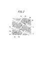
- FIG. 2 is an enlarged view of a part of the reversely inclined lateral groove of FIG.
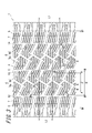
- FIG. 3 is another example of a pneumatic tire according to the present invention, and is a partial development view of a tread surface.
- FIG. 1 is a partial development view of a tread surface 1 of a tread of a pneumatic tire (hereinafter simply referred to as “tire”) according to the present invention.
- the tread surface 1 is provided with at least one circumferential main groove extending in the circumferential direction of the tread, here two circumferential main grooves 2 and 3.
- a land portion on the tread shoulder side from the tread end TE to the circumferential main groove 2 a land portion on the tread shoulder side from the other tread end TE to the circumferential main groove 3, and the circumferential main groove 2
- the land part of the tread center side between 3 is formed.
- a plurality of lateral grooves 4 extending from the circumferential main groove 2 to the circumferential main groove 3 so as to incline at an angle of, for example, less than 45 degrees with respect to the tread width direction (the equator orthogonal direction) are provided at predetermined intervals in the tire circumferential direction.
- the land portion on the tread center side is partitioned into a plurality of blocks 6.
- a plurality of lateral grooves 5 and 5 extending in the tread width direction from the circumferential main groove 2 to the tread end TE and from the circumferential main groove 3 to the other tread end TE, respectively, at a predetermined interval in the tire circumferential direction.
- the land portion on the tread shoulder side is divided into a plurality of blocks 7 and 7.
- Each block 6, 7 is provided with one or more sipes.
- a sipe When a sipe is formed in this way, the sipe opens when the block comes in contact with the snow road surface, so the friction between the block and the snow road surface increases due to the effect of the block scratching the snow road surface (edge effect), and the traction performance on the snow In addition, the brake performance can be improved.
- an open sipe when running on wet roads or when snow melts due to friction between the block and snow road surface, an open sipe can take in this water and communicate with these sipes in the circumferential direction. By draining into the main grooves 2 and 3 and the lateral grooves 4 and 5 and the reverse inclined lateral groove 8 described later, the water removal effect can be enhanced.
- the rigidity of the block is appropriately reduced, the grounding property of each block is improved, and the steering stability can be improved.
- the inclined groove extending in the direction opposite to the inclination direction with respect to the tread width direction of the lateral groove 4 is formed in the land portion on the center side of the tread so as to straddle at least two blocks, here three blocks 6. (Hereinafter referred to as “reversely inclined lateral grooves 8”).
- the block 6 is divided into two blocks, here blocks 6 a and 6 b, by a reverse inclined lateral groove 8.
- the lateral groove 4 that crosses the tread center side tread in the tread width direction is inclined with respect to the tread width direction, an edge component in the tire width direction is particularly effective, and on snow, during cornering The handling performance can be ensured.
- the lateral groove 4 is inclined in a certain direction with respect to the tread width direction as described above, especially when the vehicle equipped with the tire of the present invention travels on a low ⁇ road surface such as snow, the lateral groove 4 When the vehicle turns in the tilt direction, the tire may easily slip on the road surface and the vehicle may flow in the tilt direction (called skew).
- the tire can be prevented from flowing in the inclined direction of the lateral groove 4, so that the vehicle turns in any direction. Even so, it is possible to prevent the skew of the tire on the snow and to ensure good handling performance.
- the reversely inclined lateral groove 8 functions effectively for traction performance and braking performance when the vehicle goes straight. Further, since the reversely inclined lateral groove 8 has an edge component in the opposite direction to the lateral groove 4, it is also effective for handling performance during cornering.
- the reverse inclined lateral groove 8 is configured to straddle three blocks.
- the reverse inclined lateral groove 8 has a tread circumferential length L ⁇ b> 1 that is the length of each of the divided blocks 6 a and 6 b in the tread circumferential direction. If configured to be longer than the length L2, for example, it may be configured to straddle two blocks. This is because the above-described effects can be effectively exhibited by setting the reverse inclined lateral groove 8 to such a length.
- the reverse inclined lateral groove 8 is a bag-like groove with both ends closed.
- the reverse inclined lateral groove 8 is a bag-like groove with both ends closed.
- both ends are terminated in the block and a bag-like groove is provided, when snow enters the bag-like groove, the snow can be stepped firmly and a higher snow column shear force can be obtained. .
- the reversely inclined lateral groove 8 in the block 6 it is possible to obtain the same effect in bidirectional rotation without depending on the rotation direction of the tire.
- the end portions 9a and 9b do not divide the blocks 6a and 6b, the rigidity of the blocks 6a and 6b can be ensured. Therefore, the ground contact property of each block can be improved, and the traction performance, the brake performance, and the cornering performance can be further improved.
- the center in the tread width direction of the reversely inclined lateral groove 8 is preferably on a circumferential line passing through the center of the block 6 in which the reversely inclined lateral groove 8 is provided in the tread width direction.
- the center in the tread width direction of the reversely inclined lateral groove 8 is, as shown in FIG. 1, the midpoint A ′ of the line segment AA that is the length when the inversely inclined lateral groove 8 is projected in the tread circumferential direction. This also applies to the center in the tread width direction of the lateral groove 4 described below. Further, as shown in FIG.
- the circumferential line passing through the center of the block 6 in the tread width direction is a line segment B ⁇ that is the length when the block 6 formed with the reverse inclined lateral groove 8 is projected in the tread circumferential direction.
- the reversely inclined lateral groove 8 includes a groove that is inclined in a direction opposite to the inclination direction of the horizontal groove 4 with respect to the tread width direction, and therefore does not flow in one inclination direction during turning of the vehicle and suppresses the occurrence of skew. be able to.
- the reversely inclined horizontal groove 8 is positioned on the tread circumferential direction line at the center of the tread width direction of the horizontal groove 4, the horizontal groove 4 inclined with respect to the tread width direction and the reversely inclined horizontal groove 8 inclined with respect to the tread width direction are provided.
- the above effect is most effective when the tread width direction center of the reverse inclined lateral groove 8 is positioned on the tread width direction center of the horizontal groove 4, that is, on the tread circumferential direction line of the tread width direction center of the block 6. is there. 1 shows the case where all the blocks 6 have the same length in the width direction.
- the peripheral line passing through the center of the block 6 in the tread width direction is the block 6 having the largest area ratio occupied by the reverse inclined lateral groove 8 among the plurality of blocks 6 over which the one reverse inclined horizontal groove 8 is straddled. Is a circumferential line passing through the midpoint of the length when projected in the circumferential direction.
- FIG. 2 is an enlarged view of a part of the reversely inclined lateral groove 8 of FIG.
- the reverse inclined lateral groove 8 preferably has bent portions 10 a and 10 b in the blocks 6 a and 6 b, respectively, and the inclination angle with respect to the tread width direction is preferably changed in the groove.
- the inclination angles ⁇ m and ⁇ m of the portion from the bent portion 10 a to the end portion 9 a and the portion from the bent portion 10 b to the end portion 9 b with respect to the tread width direction are parts, i.e.
- the reverse inclined lateral groove 8 is bent in the blocks 6a and 6b, and the inclination angle ⁇ m in the vicinity of the end portions 9a and 9b is made smaller than the inclination angle ⁇ n between the bent portions 10a and 10b.
- the groove widths Wm and Wm of the portion from the bent portion 10a to the end portion 9a and the portion from the bent portion 10b to the end portion 9b of the reversely inclined lateral groove 8 are the central portion of the reversely inclined horizontal groove 8, that is, the bent portion 10a.
- 10b is preferably narrower than the groove width Wn in the portion between 10b.
- the portion from the bent portion 10a to the end portion 9a is formed in the block 6a, and the portion from the bent portion 10b to the end portion 9b is formed in the block 6b. Therefore, by reducing the groove width of these portions, Only the block part can be secured. As a result, the length of the reversely inclined lateral groove can be ensured without reducing the block rigidity.
- the inclination angles of the horizontal grooves 4 and 5 and the reverse inclined horizontal groove 8 will be described. It is preferable that the inclination angle with respect to the tread width direction of the lateral grooves 5 and 5 in both tread shoulder areas is smaller than the inclination angle with respect to the tread width direction of the lateral grooves 4 in the tread center area. Specifically, as shown in FIG. 1, the inclination angle ⁇ a with respect to the tread width direction of the horizontal groove 5 located in the tread shoulder region is larger than the inclination angle ⁇ b with respect to the tread width direction of the horizontal groove 4 located in the tread central region. Small is preferable.
- the tread shoulder region refers to a region from the outer circumferential main groove on the outermost tread to the tread end (both ends in the tread width direction of the tread surface) when two or more circumferential main grooves are provided.
- the tread central region refers to the region between the two outer circumferential main grooves on the outermost side of the tread, and in the example illustrated in FIG. 1, refers to the region between the circumferential main groove 2 and the circumferential main groove 3. Say it.
- the force received from the road surface during tire rotation is made uniform over the width direction of the block, and uneven wear of the block on the shoulder side is suppressed. be able to.
- the block in the tread shoulder region contributes to the braking performance, while the block in the center region of the tread tends to contribute to the handling performance.
- a relatively small inclination angle theta a with respect to the tread width direction of the transverse grooves 5 of the tread shoulder zone, that lateral groove wall of the block of the tread shoulder region is to be substantially perpendicular to the tread circumferential direction Brake performance can be improved.
- handling performance can be improved by making the horizontal groove 4 in the tread central region have a relatively large inclination angle.
- the inclination angle of the lateral groove 4 does not need to be constant between the circumferential main grooves 2 and 3, and may gradually increase from the tread end side toward the tread central region. Specifically, as in the example shown in FIG. 1, the inclination angle ⁇ c of the lateral groove 4 located at the center of the tread (on the tire equator C) is larger than the inclination angle ⁇ b located on the tread end side. It may be.
- the inclination angle ⁇ n of the reversely inclined lateral groove 8 with respect to the tread width direction is preferably 30 ° to 70 °. This is because when the inclination angle ⁇ n with respect to the tread width direction is set to 30 ° or more, the occurrence of skew can be effectively suppressed. When the inclination angle ⁇ n is set to 70 ° or less, the traction and brake performance is effectively ensured. Because it can. Then, for example, as shown in FIG. 1, in a region constituted by one or more blocks (three in FIG. 1) across which the reversely inclined lateral groove 8 is straddled, the circumferential length and the widthwise length of the region are substantially equal.
- the inclination angle ⁇ n of the reverse inclined lateral groove 8 with respect to the tread width direction is set to 40 ° to 60 °, and the bent portion 10a (10b) to the end 9a (9b) of the reverse inclined horizontal groove 8
- the inclination angle ⁇ m of the portion with respect to the tread width direction can be set to 10 ° to 30 °.
- the end 9a (9b) of the reversely inclined lateral groove 8 is used.
- the inclination angle ⁇ n of the reverse inclined lateral groove 8 with respect to the tread width direction is larger than the inclination angle ⁇ b of the horizontal groove 4 with respect to the tread width direction.
- the tread width direction length of the reversely inclined lateral groove 8 is larger than the length of the tread width direction of the lateral groove 4 extending in the entire tread width direction of the block because the reversely inclined lateral groove 8 is formed in the block located at the center of the tread. short.
- the lateral groove 4 and the reverse direction of the lateral groove 4 with respect to the tread width direction are obtained. This is because the reversely inclined groove 8 inclined to the above can function in a well-balanced manner and the occurrence of skew can be effectively suppressed.
- the positional relationship in the tread circumferential direction of the lateral grooves 4 and 5 is shifted from each other so that the blocks 6 and 7 adjacent to each other in the tread width direction across the circumferential main grooves 2 and 3 are in phase with each other.
- the horizontal grooves 4 and the horizontal grooves 5 may be linear.
- the circumferential main groove 2 and the circumferential main groove 3 are formed in a substantially straight shape, but the groove may be a groove that circulates in the tread circumferential direction, and may be a bent groove. Good.
- FIG. 3 shown next is a partial development view of the tread surface of another pneumatic tire according to the present invention. 3, the same components as those in FIG. 1 are denoted by the same reference numerals as those in FIG.
- the example of FIG. 3 is different from the example of FIG. 1 described above in that the tread tread surface 1 is provided with three circumferential main grooves (here, the circumferential main grooves 12, 13, and 14).
- a land portion on the tread shoulder side from the tread end TE to the circumferential main groove 12 a land portion on the tread shoulder side from the other tread end TE to the circumferential main groove 14, and the circumferential main groove 12
- a first land portion on the tread center side between 13 and a second land portion on the tread center side between the circumferential main grooves 13 and 14 are formed.
- the first land portion on the tread center side extends from the circumferential main groove 12 to the circumferential main groove 13
- the second land portion on the tread center side extends from the circumferential main groove 13 to the circumferential main groove 14.
- a plurality of lateral grooves 4 are provided at predetermined intervals in the tire circumferential direction, and the first land portion and the second land portion on the tread center side are partitioned into a plurality of blocks 6 and 6, respectively. Yes.
- the first and second land portions on the center side of the tread are inclined with respect to the tread width direction of the lateral groove 4 across at least two blocks 6 and, in this case, three blocks 6.
- a reverse inclined lateral groove 8 extending in a direction opposite to the direction is provided. In this way, it is possible to increase the number of circumferential main grooves and arrange a plurality of reverse inclined lateral grooves 8 in the tread width direction.
- the configuration of each part and the effects thereof are described above with reference to FIG. It is the same as the contents of.
- the number of circumferential main grooves may be one or four or more.
- the tire of the example has the tread pattern shown in FIG. 1 having a size of 235 / 65R16, the inclination angle ⁇ m from the bent portion to the end of the reversely inclined lateral groove is 20 °, and the inclination angle ⁇ n of the central portion is 50.
- This is a radial tire for passenger cars.
- a horizontal groove and a reverse inclination horizontal groove incline in a mutually reverse direction with respect to the tread width direction.
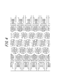
- the comparative tire 1 has the tread pattern shown in FIG. 4 in which the lateral grooves are parallel to the tread width direction, the reverse inclined lateral grooves are not provided, and four circumferential main grooves are provided. For radial tires.
- the comparative tire 2 is a radial tire for a passenger car having the tread pattern shown in FIG. 5 in which the reversely inclined lateral groove communicates with the lateral groove without terminating in the block.
- the other configurations of the comparative example tires 1 and 2 were based on the example tires. Table 1 shows the specifications of each tire.
- Example tires and Comparative Example tires were respectively mounted on a vehicle, and performance evaluation of snow brake, snow traction, snow handling, and snow cornering was performed. The results are shown in Table 2.
- the evaluation in Table 2 shows the index of the measured value of the braking distance when the brake on the snow is subjected to the test course on the snowy road surface at a speed of 40 km / h to full braking when the tire 1 of the comparative example is index 100,
- the index of the measured value of the section time when the test course of the snowy road surface is accelerated from 10 km / h to 45 km / h at the initial speed, the handling on snow is the overall evaluation index of braking performance and startability in the snowy road test course
- Snow cornering is an index of marginal feeling feeling evaluation by drivers when cornering on snowy road test courses.
- the values in Table 2 indicate that each performance improves as the numerical value increases.
- the example tire provided with the lateral groove inclined in the tread width direction in the tread and the reverse groove lateral groove inclined in the opposite direction to the lateral groove and the tread width direction is parallel to the tread width direction.
- the snow braking performance, snow traction performance, snow handling performance, and snow cornering performance are all improved. I understood.
- This invention makes it possible to provide a pneumatic tire that realizes traction performance on snow, braking performance, and cornering performance at a high level.
Landscapes
- Engineering & Computer Science (AREA)
- Mechanical Engineering (AREA)
- Tires In General (AREA)
Abstract
Description
このようなタイヤによれば、低傾斜溝と高傾斜溝のタイヤ周方向のエッジ成分によってタイヤ横方向へのエッジ効果、つまり横方向のグリップ力の一層の増加をもたらすとともに、周方向に対する高傾斜溝の傾斜の向きを、低傾斜溝の傾斜の向きとは逆方向になるように配設することで、車輌の直進性やタイヤの耐偏摩耗性を確保することができる。
(1)タイヤのトレッドの踏面を、該トレッドの周方向に延びる少なくとも一本の周方向主溝と、トレッド幅方向に対して傾斜して延びる複数本の横溝とで複数のブロックに区画し、各ブロックに一本以上のサイプを設けた空気入りタイヤであって、
該横溝のトレッド幅方向に対する傾き方向と逆向きに、少なくとも二つのブロック間に跨って延びる逆傾斜横溝を複数本有し、
該逆傾斜横溝の両端部は、各々、ブロック内で終端することを特徴とする空気入りタイヤ。
なお、逆傾斜横溝のトレッド幅方向に対する傾斜角度とは、トレッド幅方向と逆傾斜横溝とが成す鋭角側の角度のことを言う。以下記載される横溝のトレッド幅方向に対する傾斜角度についても同様である。
トレッドの踏面1には、トレッドの周方向に延びる少なくとも一本の周方向主溝、ここでは2本の周方向主溝2、3が設けられている。これにより、トレッド端TEから周方向主溝2までのトレッドショルダ側の陸部と、もう一方のトレッド端TEから周方向主溝3までのトレッドショルダ側の陸部と、周方向主溝2、3間のトレッド中央側の陸部とが形成される。
さらに、周方向主溝2から周方向主溝3へトレッド幅方向(赤道直交方向)に対して例えば45度未満の角度で傾斜して延びる横溝4がタイヤ周方向に所定の間隔を置いて複数本設けられ、トレッド中央側の陸部が、複数のブロック6に区画されている。また、周方向主溝2からトレッド端TEへ、周方向主溝3からもう一方のトレッド端TEへ、それぞれトレッド幅方向に延びる横溝5、5がタイヤ周方向に所定の間隔を置いて複数本設けられ、トレッドショルダ側の陸部が、複数のブロック7、7に区画されている。
しかしながら、横溝4は、上記のようにトレッド幅方向に対して一定方向に傾斜しているため、本発明のタイヤを装着した車両が雪上等の低μ路面上を走行する場合、特に横溝4の傾斜方向に車両が旋回する場合には、タイヤが路面上を滑りやすく、車両が傾斜方向に流れるという事態(斜行と呼ばれる)が発生してしまうことがある。従って、この横溝4の傾斜方向と反対向きの傾きを有する逆傾斜横溝8を設けることによって、タイヤが横溝4の傾斜方向に流れるのを抑制することができるので、車両がどのような方向に旋回しても、雪上におけるタイヤの斜行の発生を防ぎ、良好なハンドリング性能を確保することができる。
逆傾斜横溝8をかかる長さとすることによって、上述の効果を有効に発揮することができるからである。
また、逆傾斜横溝8の両端をブロック6内で終端させることにより、タイヤの回転方向に依存することなく、双方向の回転において同様の効果を得ることが可能となる。
また、端部9a、9bは、ブロック6a、6bを分断していないため、ブロック6a、6bの剛性を確保することができる。従って、各ブロックの接地性を高めて、トラクション性能、ブレーキ性能、コーナリング性能をさらに良好なものとすることができる。
上記の通り、逆傾斜横溝8は、横溝4のトレッド幅方向に対する傾斜方向と反対方向に傾斜する溝を備えるため、車両の旋回時に一方の傾斜方向に流れることなく、斜行の発生を抑制することができる。従って、横溝4のトレッド幅方向中心のトレッド周方向線上に逆傾斜横溝8が位置するようにすれば、トレッド幅方向に対して傾斜する横溝4及びトレッド幅方向に対して傾斜する逆傾斜横溝8を有効に機能させて、斜行の発生をさらに効果的に抑制することが可能となる。そして上記効果は、逆傾斜横溝8のトレッド幅方向中心が、横溝4のトレッド幅方向中心、すなわちブロック6のトレッド幅方向中心のトレッド周方向線上に位置するようにした場合に、最も効果的である。
なお、図1では、全てのブロック6の幅方向長さが同じである場合を示しているが、ブロック6のトレッド幅方向長さが異なる場合や、ブロック6をトレッド幅方向にずらして周方向に配置している場合がある。この場合には、ブロック6のトレッド幅方向中心を通る周線とは、一つの逆傾斜横溝8が跨っている複数のブロック6のうち、その逆傾斜横溝8の占める面積割合が最も大きいブロック6を、周方向に投影した場合の長さの中点を通る、周線のことを言うものとする。
このように、逆傾斜横溝8をブロック6a、6b内で屈曲させて、端部9a、9b近傍の傾斜角度θmを屈曲部10a及び10b間の傾斜角度θnよりも小さな角度とすることにより、雪が袋状の逆傾斜横溝8内に取り込まれた際に雪を強固に踏み固めて、雪柱せん断力を高めることができるので、雪上トラクション性能、雪上ブレーキ性能をさらに向上させることができる。
屈曲部10aから端部9aまでの部分はブロック6a内に、屈曲部10bから端部9bまでの部分はブロック6b内に形成されるため、これらの部分の溝幅を狭くすることで、その分だけ、ブロック部分を確保することができる。これにより、ブロック剛性を低下させることがない状態で、逆傾斜横溝の長さを確保することができる。
両トレッドショルダ域の横溝5、5のトレッド幅方向に対する傾斜角度は、トレッド中央域の横溝4のトレッド幅方向に対する傾斜角度よりも小さいことが好ましい。具体的には、図1に示すように、トレッドショルダ域に位置する横溝5のトレッド幅方向に対する傾斜角度θaが、トレッド中央域に位置する横溝4のトレッド幅方向に対する傾斜角度θbよりも小さいことが好ましい。
なお、本発明において、トレッドショルダ域とは、周方向主溝を2本以上設けた場合に、トレッド最外側の周方向主溝からトレッド端(トレッドの踏面のトレッド幅方向両端)までの領域のことを、図1に示す例では、周方向主溝2からトレッド端TEまでの領域と、周方向主溝3からトレッド端TEまでの領域のことを言うものとする。トレッド中央域とは、トレッド最外側の2本の周方向主溝間の領域のことを、図1に示す例では、周方向主溝2と周方向主溝3との間の領域のことを言うものとする。
また、タイヤ回転時、トレッドショルダ域のブロックはブレーキ性能に寄与し、一方、トレッド中央域のブロックはハンドリング性能に寄与し易い。従って上記のように、トレッドショルダ域の横溝5のトレッド幅方向に対する傾斜角度θaを比較的小さくして、トレッドショルダ域のブロックの横溝壁がトレッド周方向と略直交するようにすることで、ブレーキ性能を高めることができる。一方、トレッド中央域の横溝4は比較的大きな傾斜角度を有するようにすることで、ハンドリング性能を向上させることができる。
そして、例えば図1のように、逆傾斜横溝8が跨ぐ1つ以上(図1では3つ)のブロックで構成される領域において、該領域の周方向長さと幅方向長さが略等しくなるようなトレッドパターンを有する乗用車用ラジアルタイヤで、逆傾斜横溝8のトレッド幅方向に対する傾斜角度θnを40°~60°とし、逆傾斜横溝8の屈曲部10a(10b)から端部9a(9b)まで部分のトレッド幅方向に対する傾斜角度θmを10°~30°とすることができる。この場合には、逆傾斜横溝8の効果を発揮させるために、逆傾斜横溝8が延在する長さを十分に取った場合であっても、逆傾斜横溝8の端部9a(9b)からブロック6a(6b)の壁までの距離を十分確保することができるため、ブロック6a(6b)の剛性及び耐クラック性を確保することができる。
なお、逆傾斜横溝8のトレッド幅方向に対する傾斜角度θnは、横溝4のトレッド幅方向に対する傾斜角度θbよりも、大きいことが好ましい。
逆傾斜横溝8のトレッド幅方向長さは、逆傾斜横溝8はトレッド中央に位置するブロック内に形成されるため、上記ブロックのトレッド幅方向全体に延在する横溝4のトレッド幅方向長さよりも短い。従って、逆傾斜横溝8のトレッド幅方向に対する傾斜角度θnを、横溝4のトレッド幅方向に対する傾斜角度θbよりも大きくすることによって、横溝4と、トレッド幅方向に対して横溝4の逆方向に傾いた逆傾斜溝8とをバランス良く機能させて、斜行の発生を効果的に抑制することができるからである。
また、図1において、周方向主溝2及び周方向主溝3は略直線状に形成されているが、該溝はトレッド周方向に周回した溝であればよく、屈曲した溝であってもよい。
図3の例は、トレッドの踏面1に周方向主溝が3本(ここでは周方向主溝12、13、14)設けられている点が、先に説明した図1の例とは異なる。これにより、トレッド端TEから周方向主溝12までのトレッドショルダ側の陸部と、もう一方のトレッド端TEから周方向主溝14までのトレッドショルダ側の陸部と、周方向主溝12、13間のトレッド中央側の第一の陸部と、周方向主溝13、14間のトレッド中央側の第二の陸部とが形成される。
さらに、トレッド中央側の第一の陸部には周方向主溝12から周方向主溝13へ、トレッド中央側の第二の陸部には周方向主溝13から周方向主溝14へ延びる横溝4が、それぞれ、タイヤ周方向に所定の間隔を置いて複数本設けられ、トレッド中央側の第一の陸部及び第二の陸部が、それぞれ、複数のブロック6、6に区画されている。
このように、周方向主溝の本数を増やして、逆傾斜横溝8をトレッド幅方向に複数列配置することも可能であり、各部分の構成及びその効果は、図1を用いて説明した上述の内容と同様である。
一方、比較例タイヤ1は、横溝がトレッド幅方向に対して平行であり、逆傾斜横溝が設けられておらず、周方向主溝を4本設けた、図4に示したトレッドパターンを有する乗用車用ラジアルタイヤである。また、比較例タイヤ2は、逆傾斜横溝がブロック内で終端せずに横溝に連通する、図5に示したトレッドパターンを有する乗用車用ラジアルタイヤである。比較例タイヤ1、2のその他の構成は、実施例タイヤに準ずるものとした。
表1に、各タイヤの諸元を示す。


2、3 周方向主溝
4、5 横溝
6、7 ブロック
8 逆傾斜横溝
9a、9b 端部
10a、10b 屈曲部
12、13、14 周方向主溝
Claims (7)
- タイヤのトレッドの踏面を、該トレッドの周方向に延びる少なくとも一本の周方向主溝と、トレッド幅方向に対して傾斜して延びる複数本の横溝とで複数のブロックに区画し、各ブロックに一本以上のサイプを設けた空気入りタイヤであって、
該横溝のトレッド幅方向に対する傾き方向と逆向きに、少なくとも二つのブロック間に跨って延びる逆傾斜横溝を複数本有し、
該逆傾斜横溝の両端部は、各々、ブロック内で終端することを特徴とする空気入りタイヤ。 - 前記逆傾斜横溝のトレッド幅方向中心は、前記逆傾斜横溝が設けられたブロックのトレッド幅方向中心を通る周線上に在ることを特徴とする請求項1に記載の空気入りタイヤ。
- 前記逆傾斜横溝はブロック内で屈曲部を有し、該屈曲部から前記端部までのトレッド幅方向に対する傾斜角度は、前記逆傾斜横溝の中央部のトレッド幅方向に対する傾斜角度よりも小さいことを特徴とする請求項1又は2に記載の空気入りタイヤ。
- 前記逆傾斜横溝の中央部のトレッド幅方向に対する傾斜角度は、30°~70°であることを特徴とする請求項3に記載の空気入りタイヤ。
- 前記横溝のトレッド幅方向に対する傾斜角度は、トレッドショルダ域の方が、トレッドの中央域よりも小さいことを特徴とする請求項1~4のいずれか一項に記載の空気入りタイヤ。
- 前記踏面内には、二本の周方向主溝が設けられることを特徴とする請求項1~5のいずれか一項に記載の空気入りタイヤ。
- 前記逆傾斜横溝はブロック内で屈曲部を有し、該屈曲部から前記端部までの逆傾斜横溝の溝幅は、前記逆傾斜横溝の中央部の溝幅よりも狭いことを特徴とする請求項1~6のいずれか一項に記載の空気入りタイヤ。
Priority Applications (3)
| Application Number | Priority Date | Filing Date | Title |
|---|---|---|---|
| EP12760793.5A EP2689940B1 (en) | 2011-03-23 | 2012-03-16 | Pneumatic tire |
| CN201280015203.7A CN103442909B (zh) | 2011-03-23 | 2012-03-16 | 充气轮胎 |
| JP2013505813A JP5820466B2 (ja) | 2011-03-23 | 2012-03-16 | 空気入りタイヤ |
Applications Claiming Priority (2)
| Application Number | Priority Date | Filing Date | Title |
|---|---|---|---|
| JP2011-063979 | 2011-03-23 | ||
| JP2011063979 | 2011-03-23 |
Publications (1)
| Publication Number | Publication Date |
|---|---|
| WO2012127839A1 true WO2012127839A1 (ja) | 2012-09-27 |
Family
ID=46879019
Family Applications (1)
| Application Number | Title | Priority Date | Filing Date |
|---|---|---|---|
| PCT/JP2012/001860 Ceased WO2012127839A1 (ja) | 2011-03-23 | 2012-03-16 | 空気入りタイヤ |
Country Status (4)
| Country | Link |
|---|---|
| EP (1) | EP2689940B1 (ja) |
| JP (1) | JP5820466B2 (ja) |
| CN (1) | CN103442909B (ja) |
| WO (1) | WO2012127839A1 (ja) |
Cited By (5)
| Publication number | Priority date | Publication date | Assignee | Title |
|---|---|---|---|---|
| CN103350617A (zh) * | 2013-07-25 | 2013-10-16 | 厦门正新橡胶工业有限公司 | 子午线轮胎胎面结构 |
| WO2015008659A1 (ja) * | 2013-07-16 | 2015-01-22 | 住友ゴム工業株式会社 | 空気入りタイヤ |
| US20170001479A1 (en) * | 2014-01-29 | 2017-01-05 | The Yokohama Rubber Co., Ltd. | Pneumatic Tire |
| CN108349322A (zh) * | 2015-11-12 | 2018-07-31 | 株式会社普利司通 | 轮胎 |
| CN108688411A (zh) * | 2017-04-10 | 2018-10-23 | 住友橡胶工业株式会社 | 充气轮胎 |
Families Citing this family (3)
| Publication number | Priority date | Publication date | Assignee | Title |
|---|---|---|---|---|
| JP6699193B2 (ja) * | 2016-01-21 | 2020-05-27 | 住友ゴム工業株式会社 | 空気入りタイヤ |
| JP6702361B2 (ja) * | 2018-07-02 | 2020-06-03 | 横浜ゴム株式会社 | 空気入りタイヤ |
| IT201800009473A1 (it) * | 2018-10-16 | 2020-04-16 | Bridgestone Europe Nv Sa | Battistrada per pneumatico invernale e pneumatico invernale |
Citations (3)
| Publication number | Priority date | Publication date | Assignee | Title |
|---|---|---|---|---|
| JPH06143935A (ja) * | 1992-11-09 | 1994-05-24 | Bridgestone Corp | 空気入りタイヤ |
| JPH0867114A (ja) | 1994-06-21 | 1996-03-12 | Bridgestone Corp | 雪上走行および氷上走行に適した空気入りタイヤ |
| JP2008201319A (ja) | 2007-02-21 | 2008-09-04 | Sumitomo Rubber Ind Ltd | スタッドレスタイヤ |
Family Cites Families (7)
| Publication number | Priority date | Publication date | Assignee | Title |
|---|---|---|---|---|
| USD388752S (en) * | 1996-07-25 | 1998-01-06 | The Ohtsu Tire & Rubber Co., Ltd. | Automobile tire |
| JP4056304B2 (ja) * | 2002-06-24 | 2008-03-05 | 横浜ゴム株式会社 | 氷雪路用空気入りタイヤ |
| JP4927312B2 (ja) * | 2003-11-28 | 2012-05-09 | 株式会社ブリヂストン | 空気入りタイヤ |
| JP4355276B2 (ja) * | 2004-11-18 | 2009-10-28 | 住友ゴム工業株式会社 | 重荷重用空気入りタイヤ |
| JP4359262B2 (ja) * | 2005-05-13 | 2009-11-04 | 住友ゴム工業株式会社 | 空気入りタイヤ |
| JP4486592B2 (ja) * | 2005-12-29 | 2010-06-23 | 住友ゴム工業株式会社 | 重荷重用タイヤ |
| JP4166819B1 (ja) * | 2008-02-29 | 2008-10-15 | 横浜ゴム株式会社 | 空気入りタイヤ |
-
2012
- 2012-03-16 WO PCT/JP2012/001860 patent/WO2012127839A1/ja not_active Ceased
- 2012-03-16 CN CN201280015203.7A patent/CN103442909B/zh not_active Expired - Fee Related
- 2012-03-16 JP JP2013505813A patent/JP5820466B2/ja not_active Expired - Fee Related
- 2012-03-16 EP EP12760793.5A patent/EP2689940B1/en not_active Not-in-force
Patent Citations (3)
| Publication number | Priority date | Publication date | Assignee | Title |
|---|---|---|---|---|
| JPH06143935A (ja) * | 1992-11-09 | 1994-05-24 | Bridgestone Corp | 空気入りタイヤ |
| JPH0867114A (ja) | 1994-06-21 | 1996-03-12 | Bridgestone Corp | 雪上走行および氷上走行に適した空気入りタイヤ |
| JP2008201319A (ja) | 2007-02-21 | 2008-09-04 | Sumitomo Rubber Ind Ltd | スタッドレスタイヤ |
Non-Patent Citations (4)
| Title |
|---|
| "JATMA Year Book", JAPAN AUTOMOBILE TIRE MANUFACTURER'S ASSOCIATION |
| "Standards Manual", EUROPEAN TYRE AND RIM TECHNICAL ORGANISATION |
| "Year Book", TIRE AND RIM ASSOCIATION |
| See also references of EP2689940A4 * |
Cited By (12)
| Publication number | Priority date | Publication date | Assignee | Title |
|---|---|---|---|---|
| WO2015008659A1 (ja) * | 2013-07-16 | 2015-01-22 | 住友ゴム工業株式会社 | 空気入りタイヤ |
| JP2015020465A (ja) * | 2013-07-16 | 2015-02-02 | 住友ゴム工業株式会社 | 空気入りタイヤ |
| RU2655242C2 (ru) * | 2013-07-16 | 2018-05-24 | Сумитомо Раббер Индастриз, Лтд. | Пневматическая шина |
| US10005322B2 (en) | 2013-07-16 | 2018-06-26 | Sumitomo Rubber Industries, Ltd. | Pneumatic tire |
| CN103350617A (zh) * | 2013-07-25 | 2013-10-16 | 厦门正新橡胶工业有限公司 | 子午线轮胎胎面结构 |
| CN103350617B (zh) * | 2013-07-25 | 2016-03-02 | 厦门正新橡胶工业有限公司 | 子午线轮胎胎面结构 |
| US20170001479A1 (en) * | 2014-01-29 | 2017-01-05 | The Yokohama Rubber Co., Ltd. | Pneumatic Tire |
| US9770951B2 (en) * | 2014-01-29 | 2017-09-26 | The Yokohama Rubber Co., Ltd. | Pneumatic tire |
| CN108349322A (zh) * | 2015-11-12 | 2018-07-31 | 株式会社普利司通 | 轮胎 |
| JPWO2017082408A1 (ja) * | 2015-11-12 | 2018-08-30 | 株式会社ブリヂストン | タイヤ |
| CN108349322B (zh) * | 2015-11-12 | 2020-06-02 | 株式会社普利司通 | 轮胎 |
| CN108688411A (zh) * | 2017-04-10 | 2018-10-23 | 住友橡胶工业株式会社 | 充气轮胎 |
Also Published As
| Publication number | Publication date |
|---|---|
| CN103442909B (zh) | 2015-11-25 |
| JP5820466B2 (ja) | 2015-11-24 |
| EP2689940A1 (en) | 2014-01-29 |
| CN103442909A (zh) | 2013-12-11 |
| JPWO2012127839A1 (ja) | 2014-07-24 |
| EP2689940B1 (en) | 2016-11-02 |
| EP2689940A4 (en) | 2015-08-12 |
Similar Documents
| Publication | Publication Date | Title |
|---|---|---|
| JP5820466B2 (ja) | 空気入りタイヤ | |
| JP5480868B2 (ja) | 空気入りタイヤ | |
| JP5685237B2 (ja) | 空気入りタイヤ | |
| CN103832221B (zh) | 充气轮胎 | |
| JP5102711B2 (ja) | 空気入りタイヤ | |
| CN106660405B (zh) | 车辆轮胎 | |
| JP5404378B2 (ja) | 空気入りタイヤ | |
| JP5276104B2 (ja) | 空気入りタイヤ | |
| JP6139843B2 (ja) | 空気入りタイヤ | |
| JP5690339B2 (ja) | タイヤ | |
| JP5781566B2 (ja) | 空気入りタイヤ | |
| JP2013039899A (ja) | 空気入りタイヤ | |
| JP7176320B2 (ja) | タイヤ | |
| JP5844982B2 (ja) | タイヤ | |
| WO2015093390A1 (ja) | 冬用タイヤ | |
| CN113580850B (zh) | 轮胎 | |
| JP2016016694A (ja) | 冬用タイヤ | |
| JP7400429B2 (ja) | タイヤ | |
| JP5200123B2 (ja) | 重荷重用空気入りタイヤ | |
| US10232670B2 (en) | Pneumatic tire | |
| CN104512205B (zh) | 充气轮胎 | |
| WO2014006829A1 (ja) | 空気入りタイヤ | |
| JP6077288B2 (ja) | 空気入りタイヤ | |
| JP5545854B2 (ja) | タイヤ | |
| JP2011042260A (ja) | タイヤ |
Legal Events
| Date | Code | Title | Description |
|---|---|---|---|
| 121 | Ep: the epo has been informed by wipo that ep was designated in this application |
Ref document number: 12760793 Country of ref document: EP Kind code of ref document: A1 |
|
| ENP | Entry into the national phase |
Ref document number: 2013505813 Country of ref document: JP Kind code of ref document: A |
|
| REEP | Request for entry into the european phase |
Ref document number: 2012760793 Country of ref document: EP |
|
| WWE | Wipo information: entry into national phase |
Ref document number: 2012760793 Country of ref document: EP |
|
| NENP | Non-entry into the national phase |
Ref country code: DE |