WO2012127895A1 - 密封装置 - Google Patents
密封装置 Download PDFInfo
- Publication number
- WO2012127895A1 WO2012127895A1 PCT/JP2012/051023 JP2012051023W WO2012127895A1 WO 2012127895 A1 WO2012127895 A1 WO 2012127895A1 JP 2012051023 W JP2012051023 W JP 2012051023W WO 2012127895 A1 WO2012127895 A1 WO 2012127895A1
- Authority
- WO
- WIPO (PCT)
- Prior art keywords
- sealing device
- lip
- seal lip
- seal
- grease
- Prior art date
- Legal status (The legal status is an assumption and is not a legal conclusion. Google has not performed a legal analysis and makes no representation as to the accuracy of the status listed.)
- Ceased
Links
Images


Classifications
-
- F—MECHANICAL ENGINEERING; LIGHTING; HEATING; WEAPONS; BLASTING
- F16—ENGINEERING ELEMENTS AND UNITS; GENERAL MEASURES FOR PRODUCING AND MAINTAINING EFFECTIVE FUNCTIONING OF MACHINES OR INSTALLATIONS; THERMAL INSULATION IN GENERAL
- F16J—PISTONS; CYLINDERS; SEALINGS
- F16J15/00—Sealings
- F16J15/16—Sealings between relatively-moving surfaces
- F16J15/32—Sealings between relatively-moving surfaces with elastic sealings, e.g. O-rings
- F16J15/324—Arrangements for lubrication or cooling of the sealing itself
-
- C—CHEMISTRY; METALLURGY
- C10—PETROLEUM, GAS OR COKE INDUSTRIES; TECHNICAL GASES CONTAINING CARBON MONOXIDE; FUELS; LUBRICANTS; PEAT
- C10M—LUBRICATING COMPOSITIONS; USE OF CHEMICAL SUBSTANCES EITHER ALONE OR AS LUBRICATING INGREDIENTS IN A LUBRICATING COMPOSITION
- C10M171/00—Lubricating compositions characterised by purely physical criteria, e.g. containing as base-material, thickener or additive, ingredients which are characterised exclusively by their numerically specified physical properties, i.e. containing ingredients which are physically well-defined but for which the chemical nature is either unspecified or only very vaguely indicated
- C10M171/02—Specified values of viscosity or viscosity index
-
- F—MECHANICAL ENGINEERING; LIGHTING; HEATING; WEAPONS; BLASTING
- F16—ENGINEERING ELEMENTS AND UNITS; GENERAL MEASURES FOR PRODUCING AND MAINTAINING EFFECTIVE FUNCTIONING OF MACHINES OR INSTALLATIONS; THERMAL INSULATION IN GENERAL
- F16C—SHAFTS; FLEXIBLE SHAFTS; ELEMENTS OR CRANKSHAFT MECHANISMS; ROTARY BODIES OTHER THAN GEARING ELEMENTS; BEARINGS
- F16C33/00—Parts of bearings; Special methods for making bearings or parts thereof
- F16C33/72—Sealings
- F16C33/76—Sealings of ball or roller bearings
- F16C33/78—Sealings of ball or roller bearings with a diaphragm, disc, or ring, with or without resilient members
- F16C33/7816—Details of the sealing or parts thereof, e.g. geometry, material
- F16C33/782—Details of the sealing or parts thereof, e.g. geometry, material of the sealing region
- F16C33/7823—Details of the sealing or parts thereof, e.g. geometry, material of the sealing region of sealing lips
-
- F—MECHANICAL ENGINEERING; LIGHTING; HEATING; WEAPONS; BLASTING
- F16—ENGINEERING ELEMENTS AND UNITS; GENERAL MEASURES FOR PRODUCING AND MAINTAINING EFFECTIVE FUNCTIONING OF MACHINES OR INSTALLATIONS; THERMAL INSULATION IN GENERAL
- F16C—SHAFTS; FLEXIBLE SHAFTS; ELEMENTS OR CRANKSHAFT MECHANISMS; ROTARY BODIES OTHER THAN GEARING ELEMENTS; BEARINGS
- F16C33/00—Parts of bearings; Special methods for making bearings or parts thereof
- F16C33/72—Sealings
- F16C33/76—Sealings of ball or roller bearings
- F16C33/78—Sealings of ball or roller bearings with a diaphragm, disc, or ring, with or without resilient members
- F16C33/7869—Sealings of ball or roller bearings with a diaphragm, disc, or ring, with or without resilient members mounted with a cylindrical portion to the inner surface of the outer race and having a radial portion extending inward
- F16C33/7879—Sealings of ball or roller bearings with a diaphragm, disc, or ring, with or without resilient members mounted with a cylindrical portion to the inner surface of the outer race and having a radial portion extending inward with a further sealing ring
- F16C33/7883—Sealings of ball or roller bearings with a diaphragm, disc, or ring, with or without resilient members mounted with a cylindrical portion to the inner surface of the outer race and having a radial portion extending inward with a further sealing ring mounted to the inner race and of generally L-shape, the two sealing rings defining a sealing with box-shaped cross-section
-
- F—MECHANICAL ENGINEERING; LIGHTING; HEATING; WEAPONS; BLASTING
- F16—ENGINEERING ELEMENTS AND UNITS; GENERAL MEASURES FOR PRODUCING AND MAINTAINING EFFECTIVE FUNCTIONING OF MACHINES OR INSTALLATIONS; THERMAL INSULATION IN GENERAL
- F16J—PISTONS; CYLINDERS; SEALINGS
- F16J15/00—Sealings
- F16J15/16—Sealings between relatively-moving surfaces
- F16J15/32—Sealings between relatively-moving surfaces with elastic sealings, e.g. O-rings
- F16J15/3248—Sealings between relatively-moving surfaces with elastic sealings, e.g. O-rings provided with casings or supports
- F16J15/3252—Sealings between relatively-moving surfaces with elastic sealings, e.g. O-rings provided with casings or supports with rigid casings or supports
- F16J15/3256—Sealings between relatively-moving surfaces with elastic sealings, e.g. O-rings provided with casings or supports with rigid casings or supports comprising two casing or support elements, one attached to each surface, e.g. cartridge or cassette seals
- F16J15/3264—Sealings between relatively-moving surfaces with elastic sealings, e.g. O-rings provided with casings or supports with rigid casings or supports comprising two casing or support elements, one attached to each surface, e.g. cartridge or cassette seals the elements being separable from each other
-
- C—CHEMISTRY; METALLURGY
- C10—PETROLEUM, GAS OR COKE INDUSTRIES; TECHNICAL GASES CONTAINING CARBON MONOXIDE; FUELS; LUBRICANTS; PEAT
- C10N—INDEXING SCHEME ASSOCIATED WITH SUBCLASS C10M RELATING TO LUBRICATING COMPOSITIONS
- C10N2020/00—Specified physical or chemical properties or characteristics, i.e. function, of component of lubricating compositions
- C10N2020/01—Physico-chemical properties
- C10N2020/02—Viscosity; Viscosity index
-
- C—CHEMISTRY; METALLURGY
- C10—PETROLEUM, GAS OR COKE INDUSTRIES; TECHNICAL GASES CONTAINING CARBON MONOXIDE; FUELS; LUBRICANTS; PEAT
- C10N—INDEXING SCHEME ASSOCIATED WITH SUBCLASS C10M RELATING TO LUBRICATING COMPOSITIONS
- C10N2030/00—Specified physical or chemical properties which is improved by the additive characterising the lubricating composition, e.g. multifunctional additives
- C10N2030/06—Oiliness; Film-strength; Anti-wear; Resistance to extreme pressure
-
- C—CHEMISTRY; METALLURGY
- C10—PETROLEUM, GAS OR COKE INDUSTRIES; TECHNICAL GASES CONTAINING CARBON MONOXIDE; FUELS; LUBRICANTS; PEAT
- C10N—INDEXING SCHEME ASSOCIATED WITH SUBCLASS C10M RELATING TO LUBRICATING COMPOSITIONS
- C10N2040/00—Specified use or application for which the lubricating composition is intended
- C10N2040/02—Bearings
-
- C—CHEMISTRY; METALLURGY
- C10—PETROLEUM, GAS OR COKE INDUSTRIES; TECHNICAL GASES CONTAINING CARBON MONOXIDE; FUELS; LUBRICANTS; PEAT
- C10N—INDEXING SCHEME ASSOCIATED WITH SUBCLASS C10M RELATING TO LUBRICATING COMPOSITIONS
- C10N2050/00—Form in which the lubricant is applied to the material being lubricated
- C10N2050/10—Form in which the lubricant is applied to the material being lubricated semi-solid; greasy
-
- F—MECHANICAL ENGINEERING; LIGHTING; HEATING; WEAPONS; BLASTING
- F16—ENGINEERING ELEMENTS AND UNITS; GENERAL MEASURES FOR PRODUCING AND MAINTAINING EFFECTIVE FUNCTIONING OF MACHINES OR INSTALLATIONS; THERMAL INSULATION IN GENERAL
- F16C—SHAFTS; FLEXIBLE SHAFTS; ELEMENTS OR CRANKSHAFT MECHANISMS; ROTARY BODIES OTHER THAN GEARING ELEMENTS; BEARINGS
- F16C2240/00—Specified values or numerical ranges of parameters; Relations between them
- F16C2240/40—Linear dimensions, e.g. length, radius, thickness, gap
- F16C2240/54—Surface roughness
-
- F—MECHANICAL ENGINEERING; LIGHTING; HEATING; WEAPONS; BLASTING
- F16—ENGINEERING ELEMENTS AND UNITS; GENERAL MEASURES FOR PRODUCING AND MAINTAINING EFFECTIVE FUNCTIONING OF MACHINES OR INSTALLATIONS; THERMAL INSULATION IN GENERAL
- F16C—SHAFTS; FLEXIBLE SHAFTS; ELEMENTS OR CRANKSHAFT MECHANISMS; ROTARY BODIES OTHER THAN GEARING ELEMENTS; BEARINGS
- F16C2326/00—Articles relating to transporting
- F16C2326/20—Land vehicles
Definitions
- the present invention relates to a sealing device, and more particularly to a sealing device having a seal lip that is slidably in close contact with a mating member.
- the sealing device of the present invention is used, for example, as a bearing grease seal or the like in the field related to automobiles.
- a sealing device (hereinafter also referred to as a seal) is used for the purpose of preventing muddy water from entering from outside and sealing bearing grease.
- the present invention provides a sealing device having a sealing lip that is slidably in close contact with a mating member, and can achieve low friction accompanying the sliding and also suppress lip wear.
- An object of the present invention is to provide a sealing device that can be used.
- a sealing device is a sealing device having a sealing lip that is slidably in contact with a mating member, and simultaneously reduces frictional force and suppresses lip wear in the sliding.
- the sliding surface of the seal lip is provided with irregularities, and a low base oil viscosity grease is supplied to the sliding surface of the seal lip.
- the sealing device according to claim 2 of the present invention is the sealing device according to claim 1, wherein the mating member is integrally formed with a flange portion radially outward from one axial end of the cylindrical portion.
- a slinger having a substantially L-shaped cross section, wherein the seal lip is slidably in close contact with the end surface of the flange portion, and a second seal is slidably in close contact with the outer peripheral surface of the cylindrical portion.
- a lip and a third seal lip that is slidably in close contact with the outer peripheral surface of the cylindrical portion inside the second seal lip, and the unevenness is imparted to the sliding surfaces of the three seal lips, respectively.
- the low base oil viscosity grease is filled in the space between the three seal lips.
- the sealing device according to claim 3 of the present invention is the sealing device according to claim 1 or 2, characterized in that the unevenness has a size of 1.0 to 3.0 ⁇ mRa.
- the sealing device according to claim 4 of the present invention is the sealing device according to claim 1 or 2, characterized in that the unevenness has a size of 1.5 to 3.0 ⁇ mRa.
- the sealing device according to claim 5 of the present invention is the sealing device according to claim 1, 2, 3 or 4, wherein the low base oil viscosity grease has a base oil kinematic viscosity at 40 ° C. of 10 to 10. It is characterized by being a grease of 40 mm 2 / s.
- the sliding surface of the seal lip is provided with irregularities, and the low base oil viscosity grease is supplied to the sliding surface of the seal lip.
- the provision of irregularities here means that the irregularities are formed in advance, and that the grease is supplied means that the grease performs a lubricating action during the lip sliding operation as a result.
- the irregularities are fine irregularities.
- the contact area of the seal lip with the mating member is reduced, and grease is likely to intervene due to the unevenness, so the frictional force is reduced and the low base oil viscosity as grease Since the grease is supplied, the frictional force is further reduced.
- the surface of the mating member is formed as a smooth surface having a normal surface roughness. ing. Accordingly, the seal lip made of rubber-like elastic material slides on a smooth surface rather than an uneven surface, and therefore the seal lip is less likely to slide and wear.
- the mating member with which the seal lip is slidably in close contact is, for example, a half-section substantially L-shaped in which a flange portion is integrally formed from one axial end of the cylindrical portion outward in the radial direction.
- a slinger As the seal lip, for example, a first seal lip that is slidably in contact with the end surface of the flange portion of the slinger, a second seal lip that is slidably in close contact with the outer peripheral surface of the cylindrical portion, and a second seal lip And a third seal lip that is slidably in close contact with the outer peripheral surface of the cylindrical portion.
- unevenness is imparted to the sliding surfaces of the three seal lips, and the space between the first seal lip and the second seal lip and the space between the second seal lip and the third seal lip are reduced.
- the base oil viscosity grease will be filled.
- the unevenness imparted to the surface of the mating member is optimal when the surface roughness is in the range of 0.5 to 1.5 ⁇ mRa.
- unevenness is imparted to the sliding surface of the seal lip instead of the surface of the member, it is necessary to change the surface roughness because the seal lip is easily elastically deformed.
- the surface roughness is It has been found that it is desirable to make the range larger than the above case, that is, 1.0 to 3.0 ⁇ m Ra, and 1.5 to 3.0 ⁇ m Ra (equivalent to 10 to 20 ⁇ m Rz) in view of practical use.
- the grease may be dispersed by sliding to cause an increase in frictional resistance, so the base oil kinematic viscosity at 40 ° C. is 10 mm 2 / s. It is desirable to use a larger one.
- Grease used for general bearings base oil kinematic viscosity at 40 ° C. is 60 to 100 mm 2 / s
- the present invention has the following effects.
- the sealing device of the present invention since the unevenness is imparted to the sliding surface of the seal lip, the contact area of the seal lip with the mating member is reduced and the grease is likely to be interposed by the unevenness, Therefore, the frictional force is reduced, and the low base oil viscosity grease is supplied as the grease, so that the frictional force is further reduced. Moreover, since the unevenness is imparted to the sliding surface of the seal lip and not to the surface of the mating member, the surface of the mating member is formed as a smooth surface having a normal surface roughness. Accordingly, the seal lip made of rubber-like elastic material slides on a smooth surface, not an uneven surface, and therefore the seal lip is less likely to slide and wear.
- a seal that can achieve low friction accompanying sliding and can also suppress lip wear.
- the present invention includes the following embodiments.
- (1) As shown in FIG. 1, the present invention is characterized in that the lip portion of the seal is provided with irregularities and is filled with a low base oil viscosity grease.
- the present invention relates to a method for reducing the torque of a bearing grease seal.
- (3) The present invention is different from the invention described in the prior art document in that the surface roughness on the rubber side is adjusted. The torque can be reduced by increasing the surface roughness on the rubber lip side.
- the surface roughness on the metal member side that comes into sliding contact with the rubber lip is a normal finished surface, there is an advantage that the lip does not wear. Further, since the lip roughness is formed by transferring the surface of the mold to a predetermined surface roughness, there is an advantage that the roughness quality can be kept constant. Since the surface of the rubber lip is greatly elastically deformed by sliding contact with the mating metal member, a numerical range different from the roughness of the surface formed on the metal member side, which has been performed so far, is an optimum range in the case of rubber. As is clear from the examples of the present invention, this optimum range cannot be easily conceived from the invention described in the prior art document.
- FIG. 1 shows a cross section of the main part of a sealing device according to an embodiment of the present invention.
- the sealing device shown in FIG. 1 is used as a bearing grease seal in the automobile-related field, and is attached to a bearing inner ring (not shown) and rotates together with the bearing inner ring, and a bearing outer ring (not shown). It is configured by a combination with a seal lip member 21 that is attached and slidably contacts the slinger 11.
- the bearing inner ring may be a shaft or sleeve of a rotating device instead of this
- the bearing outer ring may be a housing of a rotating device instead of this.
- the slinger 11 is made of a metal material, and is integrally formed with a flange portion (outward flange portion) 11b radially outward at one end in the axial direction of the cylindrical portion 11a so as to have a substantially L-shaped cross section.
- the inner peripheral surface of the cylindrical portion 11a is fitted to the outer peripheral surface of the bearing inner ring.
- a magnetic encoder may be attached to the outer end surface 11c of the flange portion 11b.
- the seal lip member 21 is configured by a combination of an attachment ring 22 and a rubber-like elastic body 23 attached to the attachment ring 22.
- the mounting ring 22 is made of a metal material, and is formed by integrally forming a flange portion (inward flange portion) 22b radially inward at the other axial end of the cylindrical portion 22a.
- the outer peripheral surface 22a is fitted to the inner peripheral surface of the bearing outer ring.
- the rubber-like elastic body 23 is slidably in close contact with the rubber part 24 attached to the attachment ring 22 and the inner end face 11d of the flange part 11b of the slinger 11 supported by the rubber part 24.
- a third seal lip (grease lip) 27 that is also supported by the adherend rubber portion 24 inside the seal lip 26 (inside the machine) and slidably contacts the outer peripheral surface of the cylindrical portion 11a of the slinger 11 is integrated.
- the first seal lip 25 and the second seal lip 26 seal the foreign matter such as muddy water outside the bearing from entering the bearing. Because of its function against muddy water, it has an outward lip structure (a structure in which the lip end is directed to the outside of the bearing), and in particular, the diameter of the first seal lip 25 gradually increases from the base end to the tip end. It is formed to do.
- the third seal lip 27 seals the grease inside the bearing so that it does not leak to the outside of the bearing.
- the third seal lip 27 has an inward lip structure (the lip end faces toward the inside of the bearing) due to the function of the grease. Structure).
- Unevenness (not shown) is provided on the sliding surfaces 25a, 26a, 27a of the three seal lips 25, 26, 27, respectively.
- the unevenness is set to a size of 1.0 to 3.0 ⁇ mRa. Since the unevenness is a minute shape and cannot be illustrated in FIG. 1, in FIG. 1, regions where the unevenness is provided are indicated by solid lines A, B, and C, respectively.
- a sealed space 31 is formed between the first seal lip 25 and the second seal lip 26, and the second seal lip 26 and the third seal lip 26
- a sealed space 32 is also formed between the seal lips 27.
- these spaces 31 and 32 are filled with low base oil viscosity grease (not shown), respectively. It is said that.
- the low base oil viscosity grease a grease having a base oil kinematic viscosity at 40 ° C. of 10 to 40 mm 2 / s is used.
- the surface of the slinger 11 is not provided with irregularities, that is, the surface of the slinger 11 is finished as a smooth surface having a normal surface roughness.
- the sliding surfaces 25a, 26a, and 27a of the seal lips 25, 26, and 27 are provided with irregularities and the spaces 31 and 32 between the seal lips 25, 26, and 27 have a low base.
- the low base oil viscosity grease is supplied to the sliding surfaces 25a, 26a, 27a of the seal lips 25, 26, 27. If unevenness is given to the sliding surfaces 25a, 26a, 27a of the seal lips 25, 26, 27, the contact area of the seal lips 25, 26, 27 to the slinger 11 is reduced, and grease is likely to intervene due to the unevenness.
- the frictional force can be reduced, and the low base oil viscosity grease is supplied as the grease, so that the frictional force can be further reduced.
- the unevenness is imparted to the sliding surfaces 25a, 26a, 27a of the seal lips 25, 26, 27 and not to the surface of the slinger 11, so that the surface of the slinger 11 has a normal surface roughness. It is finished as a smooth surface. Therefore, since the rubber-like elastic seal lips 25, 26, 27 slide on a smooth surface rather than an uneven surface, it is possible to suppress the sliding lip 25, 26, 27 from sliding wear. Become.
- a sealing device having a sealing lip that is slidably in close contact with a mating member as in the intended purpose of the present invention low friction caused by sliding can be realized and lip wear can be suppressed.
- Table 1 shows the effect of reducing the frictional force due to the unevenness on the seal lip.
- a general bearing grease base oil kinematic viscosity at 40 ° C. is 65 mm 2 / s
- the slinger is rotated at 500 rpm with the lip member fixed to the housing.
- the frictional force was measured.
- the relative comparison is made assuming that the frictional force at the seal not provided with unevenness is 100.
- the frictional force decreases as the surface roughness of the lip increases, and in the range where the surface roughness is larger than 3.0 ⁇ mRa (equivalent to 20 ⁇ mRz), the effect of reducing the frictional force is equivalent. It has become. Since imparting excessive roughness to the lip surface leads to a decrease in the sealing performance, the surface roughness of the lip portion is set to 1.0 to 3 in order to obtain a remarkable effect of reducing the frictional force while maintaining the sealing performance. From the viewpoint of practical use, it is preferably 1.5 to 3.0 ⁇ m Ra (equivalent to 10 to 20 ⁇ m Rz).
- Table 3 shows the effect of reducing the frictional force by providing irregularities on the seal lip and using the low base oil viscosity grease.
- the test conditions are the same as those shown in Table 1, and the frictional force of a seal that is not provided with irregularities with grease having a base oil kinematic viscosity at 40 ° C. of 65 mm 2 / s is 100.
- the drastic friction reduction effect can be anticipated by using a low base oil viscosity grease. This reduction in friction can be expected to improve fuel efficiency by reducing friction loss and to improve seal life by suppressing wear.
Landscapes
- Engineering & Computer Science (AREA)
- General Engineering & Computer Science (AREA)
- Mechanical Engineering (AREA)
- Chemical & Material Sciences (AREA)
- Chemical Kinetics & Catalysis (AREA)
- General Chemical & Material Sciences (AREA)
- Oil, Petroleum & Natural Gas (AREA)
- Organic Chemistry (AREA)
- Sealing Of Bearings (AREA)
- Sealing With Elastic Sealing Lips (AREA)
- Lubricants (AREA)
Abstract
相手部材に摺動自在に密接するシールリップを有する密封装置において、前記摺動に伴う低摩擦化を実現することができ、しかもリップ摩耗を抑制することもできる密封装置を提供する。この目的を達成するため、相手部材に摺動自在に密接するシールリップを有する密封装置において、前記摺動における摩擦力の低減およびリップ摩耗の抑制を同時に実現すべく前記シールリップの摺動面に凹凸を付与するとともに前記シールリップの摺動面に低基油粘度グリースを供給することを特徴とする。凹凸は、1.0~3.0μmRaの大きさとし、低基油粘度グリースは、40℃での基油動粘度が10~40mm2/sのグリースとするのが望ましい。
Description
本発明は、密封装置に係り、更に詳しくは、相手部材に摺動自在に密接するシールリップを有する密封装置に関する。本発明の密封装置は例えば、自動車関連の分野において、ベアリンググリースシール等として用いられる。
例えば自動車の軸受ユニットには、外部からの泥水侵入の防止およびベアリンググリースの密封を目的として密封装置(以下、シールとも称する)が使用されている。
近年、自動車の燃費向上のための取り組みとして、対象シールにおいても低摩擦化(低トルク化)が求められており、例えば図5に示す従来技術では、リップ摺接面(シールリップ51が摺動自在に密接する相手部材52の表面)53に凹凸(ディンプル)54を付与すること等による対策が提案されている(特許文献1参照)。
しかしながら、このようにリップ摺接面53に凹凸54を付与すると、ゴム状弾性体製のシールリップ51がこの凹凸54に対して摺動することになるために、シールリップ51の摺動摩耗を促進してしまい、よってシール性の悪化につながる問題がある。
また、上記特許文献1を含めて、本発明に対する先行技術文献としては、以下のものがある。
しかしながら、これらの文献に記載された発明はいずれも上記したようにリップ摺接面(シールリップが摺動自在に密接する相手部材の表面)に凹凸を付与するものとなっており、よって本発明とは構成を異にしている。
本発明は以上の点に鑑みて、相手部材に摺動自在に密接するシールリップを有する密封装置において、前記摺動に伴う低摩擦化を実現することができ、しかもリップ摩耗を抑制することもできる密封装置を提供することを目的とする。
上記目的を達成するため、本発明の請求項1による密封装置は、相手部材に摺動自在に密接するシールリップを有する密封装置において、前記摺動における摩擦力の低減およびリップ摩耗の抑制を同時に実現すべく前記シールリップの摺動面に凹凸を付与するとともに前記シールリップの摺動面に低基油粘度グリースを供給することを特徴とする。
また、本発明の請求項2による密封装置は、上記した請求項1記載の密封装置において、前記相手部材は、筒状部の軸方向一端から径方向外方へ向けてフランジ部を一体成形した半裁断面ほぼL字形のスリンガーであり、前記シールリップは、前記フランジ部の端面に摺動自在に密接する第1シールリップと、前記筒状部の外周面に摺動自在に密接する第2シールリップと、前記第2シールリップの内側で同じく前記筒状部の外周面に摺動自在に密接する第3シールリップと、を備え、前記3つのシールリップの摺動面にそれぞれ前記凹凸が付与されるとともに前記3つのシールリップ間の空間にそれぞれ前記低基油粘度グリースが充填されることを特徴とする。
また、本発明の請求項3による密封装置は、上記した請求項1または2記載の密封装置において、前記凹凸は、1.0~3.0μmRaの大きさであることを特徴とする。
また、本発明の請求項4による密封装置は、上記した請求項1または2記載の密封装置において、前記凹凸は、1.5~3.0μmRaの大きさであることを特徴とする。
更にまた、本発明の請求項5による密封装置は、上記した請求項1、2、3または4記載の密封装置において、前記低基油粘度グリースは、40℃での基油動粘度が10~40mm2/sのグリースであることを特徴とする。
上記構成を備える本発明の密封装置においては、シールリップの摺動面に凹凸が付与されるとともに、シールリップの摺動面に低基油粘度グリースが供給される構成とされている。ここに凹凸が付与されるとは、凹凸が予め形成されることを云い、グリースが供給されるとは、その結果としてグリースがリップ摺動作動時に潤滑作用を行なうことを云う。凹凸は、微細な凹凸である。
シールリップの摺動面に凹凸が付与されると、シールリップの相手部材に対する接触面積が縮小するとともに凹凸によってグリースが介在しやすくなるために、摩擦力が低減され、しかもグリースとして低基油粘度グリースが供給されるために、摩擦力が一層低減される。また本発明によれば、凹凸はシールリップの摺動面に付与されるものであって相手部材の表面には付与されないため、相手部材の表面は通常の表面粗さを備える平滑面として成形されている。したがってゴム状弾性体製のシールリップが摺動するのが凹凸面ではなく平滑面であるため、シールリップが摺動摩耗しにくいものとなる。
尚、ゴム状弾性体製のシールリップに凹凸を付与するには、ショットブラスト加工、放電加工、シボ加工またはレーザ加工等により表面を凹凸処理した金型を用いてシールリップを成形することが望ましく、これによれば、金型の寿命管理を適切に実施することにより、常に安定した成形品を提供することが可能となる。
また本発明の密封装置において、シールリップが摺動自在に密接する相手部材としては例えば、筒状部の軸方向一端から径方向外方へ向けてフランジ部を一体成形した半裁断面ほぼL字形のスリンガーである。またシールリップとしては例えば、前記スリンガーのフランジ部の端面に摺動自在に密接する第1シールリップと、筒状部の外周面に摺動自在に密接する第2シールリップと、第2シールリップの内側で同じく筒状部の外周面に摺動自在に密接する第3シールリップとを備えるものである。そしてこれらの場合、前記3つのシールリップの摺動面にそれぞれ凹凸が付与されるとともに第1シールリップおよび第2シールリップ間の空間ならびに第2シールリップおよび第3シールリップ間の空間にそれぞれ低基油粘度グリースが充填されることになる。
上記特許文献1に記載された発明において、相手部材の表面に付与される凹凸は、その表面粗さが0.5~1.5μmRaの範囲で最適とされているが、本発明のように相手部材の表面ではなくシールリップの摺動面に凹凸を付与する場合には、シールリップが弾性変形しやすいものであるために、その表面粗さの大きさを変更する必要がある。このため本願発明者らが鋭意検討した結果として、シールリップの摺動面に付与される凹凸について、シール性を維持しつつ、顕著な摩擦力の低減効果を得るためには、表面粗さは上記の場合よりも大きく、すなわち1.0~3.0μmRa、より実用面を考慮すれば1.5~3.0μmRa(10~20μmRz相当)の範囲とするのが望ましいことが判明した。
一方、グリースについては、特に基油動粘度が低いものについては、摺動によってグリースが離散し、摩擦抵抗の増加を引き起こす可能性があるため、40℃での基油動粘度が10mm2/sより大きなものを用いることが望ましい。一般的なベアリング用として用いられるグリース(40℃での基油動粘度が60~100mm2/s)でも、リップ部の粗さによる低摩擦化は期待できるが、より顕著な低摩擦効果を得るためには、40℃での基油動粘度が10~40mm2/sのグリースを用いることが望ましい。
本発明は、以下の効果を奏する。
すなわち、本発明の密封装置においては上記したように、シールリップの摺動面に凹凸が付与されるために、シールリップの相手部材に対する接触面積が縮小するとともに凹凸によってグリースが介在しやすくなり、よって摩擦力が低減され、しかもグリースとして低基油粘度グリースが供給されるため、摩擦力が一層低減される。また、凹凸はシールリップの摺動面に付与され相手部材の表面に付与されないため、相手部材の表面は通常の表面粗さを備える平滑面として成形されている。したがってゴム状弾性体製のシールリップが摺動するのが凹凸面でなく平滑面であるため、シールリップが摺動摩耗しにくくなる。したがって本発明所期の目的どおり、相手部材に摺動自在に密接するシールリップを有する密封装置において、摺動に伴う低摩擦化を実現することができ、しかもリップ摩耗を抑制することもできる密封装置を提供することができる。
本発明には、以下の実施形態が含まれる。
(1)本発明は、図1に示すように、シールのリップ部に凹凸を付与し、低基油粘度グリースが充填されていることを特徴とする。
(2)本発明は、ベアリンググリースシールの低トルク化方法に関わり、スリンガに摺接するシールリップ部表面の粗さをRa=1.0~3.0μm、より実用面を考慮すれば1.5~3.0μmに調節とする点に特徴を有する。さらに低基油粘度のグリースを併用することで、トルクは一層低下する。
(3)本発明は、ゴム側の表面粗さを調整する点で、先行技術文献記載の発明とは手法が異なる。ゴムリップ側の表面粗さを大きくすることで低トルク化が達成されるが、これと摺接する金属部材側の表面粗さは通常の仕上げ面であるためリップが摩耗しないという利点がある。また、リップの粗さは金型表面を所定の表面粗さに仕上げることでこれを転写して成形されるので、粗さ品質が一定に確保できる利点もある。尚、相手金属部材との摺接によりゴムリップ表面は大きく弾性変形するので、これまで行なわれてきた金属部材側に形成する表面の粗さとは異なる数値範囲がゴムの場合の最適範囲になる。本発明の実施例から明らかなように、この最適範囲は先行技術文献記載の発明から容易に想到できるものではない。
つぎに本発明の実施例を図面にしたがって説明する。
図1は、本発明の実施例に係る密封装置の要部断面を示している。
図1の密封装置は、自動車関連分野においてベアリンググリースシールとして用いられるものであって、ベアリング内輪(図示せず)に装着されてベアリング内輪とともに回転するスリンガー11と、ベアリング外輪(図示せず)に装着されてスリンガー11に摺動自在に密接するシールリップ部材21との組み合わせにより構成されている。尚、発明として、ベアリング内輪はこれに代えて回転機器の軸やスリーブなどであっても良く、ベアリング外輪はこれに代えて回転機器のハウジングなどであっても良い。
スリンガー11は、金属材よりなり、筒状部11aの軸方向一方の端部に径方向外方へ向けてフランジ部(外向きフランジ部)11bを一体成形することにより半裁断面ほぼL字形に成形されたものであって、筒状部11aの内周面をもってベアリング内輪の外周面に嵌合される。フランジ部11bの外側端面11cには、磁気エンコーダが被着される場合もある。
シールリップ部材21は、取付環22と、この取付環22に被着されたゴム状弾性体23との組み合わせにより構成されている。取付環22は、金属材よりなり、筒状部22aの軸方向他方の端部に径方向内方へ向けてフランジ部(内向きフランジ部)22bを一体成形したものであって、筒状部22aの外周面をもってベアリング外輪の内周面に嵌合される。ゴム状弾性体23は、取付環22に被着された被着ゴム部24と、この被着ゴム部24に支持されてスリンガー11のフランジ部11bの内側端面11dに摺動自在に密接する第1シールリップ(サイドリップ)25と、同じく被着ゴム部24に支持されてスリンガー11の筒状部11aの外周面に摺動自在に密接する第2シールリップ(ラジアルリップ)26と、第2シールリップ26の内側(機内側)で同じく被着ゴム部24に支持されてスリンガー11の筒状部11aの外周面に摺動自在に密接する第3シールリップ(グリースリップ)27とを一体に有している。尚、図1では、これらシールリップ25,26,27の自由状態を描いているため、これらシールリップ25,26,27が摺動する相手部材であるスリンガー11はこれを仮想の鎖線で描いている。
上記3つのシールリップ25,26,27のうち、第1シールリップ25および第2シールリップ26はそれぞれ、ベアリング外部の泥水等の異物がベアリング内部へ侵入しないようにこれをシールするものであって、その対泥水の機能からして外向きのリップ構造(リップ端がベアリング外部へ向けられた構造)とされ、特に第1シールリップ25はその基端から先端へかけて径寸法が徐々に拡大するように形成されている。また第3シールリップ27は、ベアリング内部のグリースがベアリング外部へ漏洩しないようにこれをシールするものであって、その対グリースの機能からして内向きのリップ構造(リップ端がベアリング内部へ向けられた構造)とされている。
上記3つのシールリップ25,26,27の摺動面25a,26a,27aにはそれぞれ、凹凸(図示せず)が付与されている。凹凸としては、1.0~3.0μmRaの大きさに設定されたものが付与されている。凹凸は微細な形状であって図1に図示できないことから、図1では、この凹凸が付与される領域をそれぞれ実線A、B、Cをもって示している。
また、上記3つのシールリップ25,26,27がそれぞれスリンガー11に密接すると、第1シールリップ25および第2シールリップ26間に密閉状の空間31が形成され、第2シールリップ26および第3シールリップ27間にも密閉状の空間32が形成されることになるが、当該密封装置ではその使用時に、これら空間31,32にそれぞれ低基油粘度グリース(図示せず)が充填されるものとされている。低基油粘度グリースとしては特に、40℃での基油動粘度が10~40mm2/sのグリースが用いられる。
また、当該密封装置では、スリンガー11の表面に凹凸の類は付与されておらず、すなわちスリンガー11の表面は、通常の表面粗さを備える平滑面として仕上げられている。
上記構成の密封装置においては、各シールリップ25,26,27の摺動面25a,26a,27aに凹凸が付与されるとともに、各シールリップ25,26,27間の空間31,32に低基油粘度グリースが充填される結果として各シールリップ25,26,27の摺動面25a,26a,27aに低基油粘度グリースが供給される構成とされている。シールリップ25,26,27の摺動面25a,26a,27aに凹凸が付与されると、シールリップ25,26,27のスリンガー11に対する接触面積が縮小するとともに凹凸によってグリースが介在しやすくなるために、摩擦力を低減させることが可能となり、しかもグリースとして低基油粘度グリースが供給されるために、摩擦力を一層低減させることが可能となる。
また、上記構成の密封装置によると、凹凸はシールリップ25,26,27の摺動面25a,26a,27aに付与されスリンガー11の表面に付与されないため、スリンガー11の表面は通常の表面粗さを備える平滑面として仕上げられている。したがってゴム状弾性体製のシールリップ25,26,27が摺動するのが凹凸面でなく平滑面であるため、シールリップ25,26,27が摺動摩耗するのを抑制することが可能となる。
したがって以上により、本発明所期の目的どおり、相手部材に摺動自在に密接するシールリップを有する密封装置において、摺動に伴う低摩擦化を実現することができ、しかもリップ摩耗を抑制することもできる密封装置を提供することができる。
つぎに、上記各数値の特定について説明する。
シールリップへの凹凸付与による摩擦力の低減効果を表1(図2)に示す。一般的なベアリング用グリース(40℃での基油動粘度が65mm2/s)をリップ間の空間に封入し、ハウジングにリップ部材を固定した状態で、スリンガーを回転数500rpmで回転させたときの摩擦力を測定した。尚、凹凸を付与していないシールでの摩擦力を100として、相対比較している。結果としては表1に示すとおり、摩擦力は、リップの表面粗さが大きくなるほど低下しており、表面粗さが3.0μmRa(20μmRz相当)よりも大きな範囲では摩擦力の低減効果は同等となっている。リップ面の過大な粗さ付与はシール性の低下につながるため、シール性を維持しつつ、顕著な摩擦力の低減効果を得るためには、リップ部の表面粗さを1.0~3.0μmRa、より実用面を考慮すれば1.5~3.0μmRa(10~20μmRz相当)とすることが望ましい。
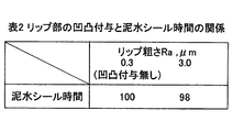
また、シールリップへの凹凸付与によるシール性(シールの使用環境の点から、特に外部からの泥水侵入に対するシール性)への影響を確認するため、表面粗さ3.0μmRaの凹凸処理を施したシールによる評価を実施した。試験は、シールの軸中心まで泥水(水+関東ローム粉JIS8種)が浸漬した状態で、一般的なベアリング用グリース(40℃での基油動粘度が65mm2/s)をリップ間の空間に封入し、スリンガーを1000rpmで回転させ、泥水が侵入するまでの時間で評価した。凹凸を付与していないシールの泥水シール時間を100として、相対比較した結果を表2(図3)に示す。表面粗さ3.0μmRaの凹凸を付与したシールでも、泥水に対するシール性は、凹凸を付与していないシールと同等であり、粗さ3.0μmRa以下であれば、シール性を維持しつつ低摩擦効果を得られるといえる。
続いて、シールリップへの凹凸付与と低基油粘度グリース使用による摩擦力の低減効果を表3(図4)に示す。試験条件は表1で示したものと同様であり、40℃での基油動粘度が65mm2/sのグリースで凹凸を付与していないシールの摩擦力を100としている。これにより、リップへの凹凸付与に加え、低基油粘度グリースを用いることで、より大幅な摩擦低減効果を見込むことができる。この低摩擦化により、摩擦損失低減による燃費向上、摩耗の抑制によるシール寿命の向上を期待することができる。
11 スリンガー(相手部材)
11a,22a 筒状部
11b,22b フランジ部
11c,11d 端面
21 シールリップ部材
22 取付環
23 ゴム状弾性体
24 被着ゴム部
25,26,27 シールリップ
25a,26a,27a 摺動面
31,32 空間
A,B,C 凹凸付与領域
11a,22a 筒状部
11b,22b フランジ部
11c,11d 端面
21 シールリップ部材
22 取付環
23 ゴム状弾性体
24 被着ゴム部
25,26,27 シールリップ
25a,26a,27a 摺動面
31,32 空間
A,B,C 凹凸付与領域
Claims (5)
- 相手部材に摺動自在に密接するシールリップを有する密封装置において、
前記摺動における摩擦力の低減およびリップ摩耗の抑制を同時に実現すべく前記シールリップの摺動面に凹凸を付与するとともに前記シールリップの摺動面に低基油粘度グリースを供給することを特徴とする密封装置。 - 請求項1記載の密封装置において、
前記相手部材は、筒状部の軸方向一端から径方向外方へ向けてフランジ部を一体成形した半裁断面ほぼL字形のスリンガーであり、
前記シールリップは、前記フランジ部の端面に摺動自在に密接する第1シールリップと、前記筒状部の外周面に摺動自在に密接する第2シールリップと、前記第2シールリップの内側で同じく前記筒状部の外周面に摺動自在に密接する第3シールリップと、を備え、
前記3つのシールリップの摺動面にそれぞれ前記凹凸が付与されるとともに前記3つのシールリップ間の空間にそれぞれ前記低基油粘度グリースが充填されることを特徴とする密封装置。 - 請求項1または2記載の密封装置において、
前記凹凸は、1.0~3.0μmRaの大きさであることを特徴とする密封装置。 - 請求項1または2記載の密封装置において、
前記凹凸は、1.5~3.0μmRaの大きさであることを特徴とする密封装置。 - 請求項1、2、3または4記載の密封装置において、
前記低基油粘度グリースは、40℃での基油動粘度が10~40mm2/sのグリースであることを特徴とする密封装置。
Priority Applications (2)
| Application Number | Priority Date | Filing Date | Title |
|---|---|---|---|
| CN2012800134378A CN103459902A (zh) | 2011-03-18 | 2012-01-19 | 密封装置 |
| EP12760861.0A EP2687761B1 (en) | 2011-03-18 | 2012-01-19 | Sealing device |
Applications Claiming Priority (2)
| Application Number | Priority Date | Filing Date | Title |
|---|---|---|---|
| JP2011060410A JP5757455B2 (ja) | 2011-03-18 | 2011-03-18 | 密封装置 |
| JP2011-060410 | 2011-03-18 |
Publications (1)
| Publication Number | Publication Date |
|---|---|
| WO2012127895A1 true WO2012127895A1 (ja) | 2012-09-27 |
Family
ID=46879065
Family Applications (1)
| Application Number | Title | Priority Date | Filing Date |
|---|---|---|---|
| PCT/JP2012/051023 Ceased WO2012127895A1 (ja) | 2011-03-18 | 2012-01-19 | 密封装置 |
Country Status (4)
| Country | Link |
|---|---|
| EP (1) | EP2687761B1 (ja) |
| JP (1) | JP5757455B2 (ja) |
| CN (2) | CN108286609A (ja) |
| WO (1) | WO2012127895A1 (ja) |
Cited By (4)
| Publication number | Priority date | Publication date | Assignee | Title |
|---|---|---|---|---|
| JP2014095441A (ja) * | 2012-11-09 | 2014-05-22 | Denso Corp | 防振ブッシュ及びその取付方法、電子装置 |
| CN109983244A (zh) * | 2016-11-25 | 2019-07-05 | Nok株式会社 | 密封装置以及轮毂轴承 |
| WO2024013954A1 (ja) | 2022-07-14 | 2024-01-18 | 株式会社ハーモニック・ドライブ・システムズ | 金属製のシールリングを備えた封止機構 |
| US20240068519A1 (en) * | 2022-08-23 | 2024-02-29 | Nok Corporation | Sealing Device for Hub Bearing |
Families Citing this family (18)
| Publication number | Priority date | Publication date | Assignee | Title |
|---|---|---|---|---|
| JP6523994B2 (ja) * | 2015-03-09 | 2019-06-05 | Ntn株式会社 | シール付軸受 |
| JP6743378B2 (ja) * | 2015-12-02 | 2020-08-19 | Nok株式会社 | 密封装置用補助シール |
| JP6649818B2 (ja) * | 2016-03-14 | 2020-02-19 | 光洋シーリングテクノ株式会社 | 密封部材 |
| JP7049053B2 (ja) * | 2016-10-26 | 2022-04-06 | Nok株式会社 | 密封装置 |
| JP2018071603A (ja) * | 2016-10-26 | 2018-05-10 | Nok株式会社 | 密封装置 |
| JP2018071604A (ja) * | 2016-10-26 | 2018-05-10 | Nok株式会社 | 密封装置 |
| JP2018084301A (ja) * | 2016-11-25 | 2018-05-31 | 内山工業株式会社 | オイルシール及びオイルシールの製造方法 |
| JP6520976B2 (ja) | 2017-03-22 | 2019-05-29 | 株式会社ジェイテクト | 密封型スラスト軸受 |
| JP7164335B2 (ja) * | 2018-07-02 | 2022-11-01 | 光洋シーリングテクノ株式会社 | 密封装置 |
| CN109505862A (zh) * | 2019-01-08 | 2019-03-22 | 湖北新火炬科技有限公司 | 一种新密封的汽车轮毂轴承 |
| WO2022107882A1 (ja) | 2020-11-20 | 2022-05-27 | 日本精工株式会社 | グリース組成物及び転動装置 |
| WO2022200693A1 (fr) | 2021-03-23 | 2022-09-29 | Hutchinson | Ensemble de joint d'étanchéité, palier à roulement comprenant un tel ensemble |
| JP2022155413A (ja) * | 2021-03-30 | 2022-10-13 | Ntn株式会社 | 密封型転がり軸受 |
| JP2022155415A (ja) * | 2021-03-30 | 2022-10-13 | Ntn株式会社 | 密封型転がり軸受 |
| JP2022190377A (ja) * | 2021-06-14 | 2022-12-26 | Ntn株式会社 | シール付軸受 |
| JP2023132691A (ja) * | 2022-03-11 | 2023-09-22 | Ntn株式会社 | 車輪用軸受装置 |
| JP2023151691A (ja) * | 2022-03-31 | 2023-10-16 | 出光興産株式会社 | グリース組成物 |
| KR102735894B1 (ko) * | 2024-05-03 | 2024-12-02 | (주)진양오일씰 | 베어링 씰 |
Citations (7)
| Publication number | Priority date | Publication date | Assignee | Title |
|---|---|---|---|---|
| WO2003091573A1 (en) | 2002-04-23 | 2003-11-06 | Nsk Ltd. | Seal device for water pump, rotation supporting device for water pump, and assembly method for water pump |
| WO2006064908A1 (ja) | 2004-12-16 | 2006-06-22 | Uchiyama Manufacturing Corp. | 回転部材のシール構造 |
| JP2008069882A (ja) * | 2006-09-14 | 2008-03-27 | Ntn Corp | グリース封入密封型転がり軸受 |
| JP2008298106A (ja) | 2007-05-29 | 2008-12-11 | Ntn Corp | 車輪用軸受装置 |
| WO2009144785A1 (ja) * | 2008-05-27 | 2009-12-03 | 日本精工株式会社 | 転がり軸受 |
| JP2010078140A (ja) * | 2008-08-29 | 2010-04-08 | Uchiyama Manufacturing Corp | 密封装置 |
| JP2010531966A (ja) | 2007-06-29 | 2010-09-30 | エスエヌエール ルルモン | 向上した動的挙動を有するローラベアリングおよびシーリング結合部 |
Family Cites Families (14)
| Publication number | Priority date | Publication date | Assignee | Title |
|---|---|---|---|---|
| DE4123392A1 (de) * | 1991-07-15 | 1993-01-21 | Wolf Woco & Co Franz J | Wellendichtring |
| US6186507B1 (en) * | 1997-09-25 | 2001-02-13 | Michael R. Oldenburg | Retrofittable severe duty seal for a shaft |
| JP3656530B2 (ja) * | 2000-08-24 | 2005-06-08 | 日本精工株式会社 | エンコーダ付組み合わせシールリングとこれを組み込んだ車輪支持用転がり軸受ユニット |
| JP3793746B2 (ja) * | 2002-07-02 | 2006-07-05 | 株式会社ジェイテクト | 摺動部材および密封装置 |
| JP4243698B2 (ja) * | 2003-03-17 | 2009-03-25 | Nok株式会社 | 密封装置 |
| CN2752528Y (zh) * | 2004-06-15 | 2006-01-18 | 万向钱潮股份有限公司 | 轮毂轴承单元密封结构 |
| US20070278748A1 (en) * | 2004-07-16 | 2007-12-06 | Nok Corporation | Sealing Device |
| JP2008057756A (ja) * | 2006-09-04 | 2008-03-13 | Kayaba Ind Co Ltd | 往復動用オイルシール |
| JP5041137B2 (ja) * | 2007-01-29 | 2012-10-03 | Nok株式会社 | 密封装置 |
| JP5168453B2 (ja) * | 2007-03-30 | 2013-03-21 | Nok株式会社 | 密封装置 |
| JP2009041708A (ja) * | 2007-08-10 | 2009-02-26 | Nok Corp | 密封装置 |
| WO2009103314A1 (de) * | 2008-02-20 | 2009-08-27 | Carl Freudenberg Kg | Dichtungsanordnung und radialwellendichtring daraus |
| CN201475175U (zh) * | 2009-05-12 | 2010-05-19 | 浙江万向精工有限公司 | 轮毂轴承单元密封结构 |
| EP2290269B1 (de) * | 2009-08-26 | 2016-07-06 | Carl Freudenberg KG | Dichtung |
-
2011
- 2011-03-18 JP JP2011060410A patent/JP5757455B2/ja active Active
-
2012
- 2012-01-19 CN CN201810171228.5A patent/CN108286609A/zh active Pending
- 2012-01-19 CN CN2012800134378A patent/CN103459902A/zh active Pending
- 2012-01-19 WO PCT/JP2012/051023 patent/WO2012127895A1/ja not_active Ceased
- 2012-01-19 EP EP12760861.0A patent/EP2687761B1/en active Active
Patent Citations (7)
| Publication number | Priority date | Publication date | Assignee | Title |
|---|---|---|---|---|
| WO2003091573A1 (en) | 2002-04-23 | 2003-11-06 | Nsk Ltd. | Seal device for water pump, rotation supporting device for water pump, and assembly method for water pump |
| WO2006064908A1 (ja) | 2004-12-16 | 2006-06-22 | Uchiyama Manufacturing Corp. | 回転部材のシール構造 |
| JP2008069882A (ja) * | 2006-09-14 | 2008-03-27 | Ntn Corp | グリース封入密封型転がり軸受 |
| JP2008298106A (ja) | 2007-05-29 | 2008-12-11 | Ntn Corp | 車輪用軸受装置 |
| JP2010531966A (ja) | 2007-06-29 | 2010-09-30 | エスエヌエール ルルモン | 向上した動的挙動を有するローラベアリングおよびシーリング結合部 |
| WO2009144785A1 (ja) * | 2008-05-27 | 2009-12-03 | 日本精工株式会社 | 転がり軸受 |
| JP2010078140A (ja) * | 2008-08-29 | 2010-04-08 | Uchiyama Manufacturing Corp | 密封装置 |
Cited By (7)
| Publication number | Priority date | Publication date | Assignee | Title |
|---|---|---|---|---|
| JP2014095441A (ja) * | 2012-11-09 | 2014-05-22 | Denso Corp | 防振ブッシュ及びその取付方法、電子装置 |
| CN109983244A (zh) * | 2016-11-25 | 2019-07-05 | Nok株式会社 | 密封装置以及轮毂轴承 |
| US10794428B2 (en) | 2016-11-25 | 2020-10-06 | Nok Corporation | Sealing device and hub bearing |
| CN109983244B (zh) * | 2016-11-25 | 2021-02-26 | Nok株式会社 | 密封装置以及轮毂轴承 |
| WO2024013954A1 (ja) | 2022-07-14 | 2024-01-18 | 株式会社ハーモニック・ドライブ・システムズ | 金属製のシールリングを備えた封止機構 |
| US20240068519A1 (en) * | 2022-08-23 | 2024-02-29 | Nok Corporation | Sealing Device for Hub Bearing |
| US12529397B2 (en) * | 2022-08-23 | 2026-01-20 | Nok Corporation | Sealing device for hub bearing |
Also Published As
| Publication number | Publication date |
|---|---|
| JP5757455B2 (ja) | 2015-07-29 |
| EP2687761A4 (en) | 2015-05-27 |
| JP2012193835A (ja) | 2012-10-11 |
| EP2687761B1 (en) | 2018-01-03 |
| CN108286609A (zh) | 2018-07-17 |
| EP2687761A1 (en) | 2014-01-22 |
| CN103459902A (zh) | 2013-12-18 |
Similar Documents
| Publication | Publication Date | Title |
|---|---|---|
| JP5757455B2 (ja) | 密封装置 | |
| JP6076971B2 (ja) | 摺動部品 | |
| JP5995967B2 (ja) | 摺動部品 | |
| EP2881631B1 (en) | Sealing device | |
| JPWO2013176011A1 (ja) | 摺動部品 | |
| CN102203445B (zh) | 带有密封件的轴承 | |
| WO2006064908A1 (ja) | 回転部材のシール構造 | |
| WO2014024741A1 (ja) | 摺動部品 | |
| JP2015014303A (ja) | 密封装置 | |
| CN104131994A (zh) | 机械密封件 | |
| WO2018047820A1 (ja) | シール付軸受 | |
| JPWO2012132731A1 (ja) | 密封装置及び密封構造 | |
| JP7199225B2 (ja) | 密封装置および密封構造 | |
| JP2018084318A (ja) | 密封装置および密封構造 | |
| JP2017180739A (ja) | シール付軸受 | |
| JP2010265949A (ja) | 密封装置 | |
| JP3201303U (ja) | 密封装置 | |
| JP7003683B2 (ja) | アンギュラ玉軸受、軸受装置、及び主軸装置 | |
| JP5926061B2 (ja) | 密封型転がり軸受 | |
| JP2017067268A (ja) | 密封装置 | |
| WO2020255591A1 (ja) | 密封装置 | |
| US10330202B2 (en) | Sealing device | |
| KR20200051759A (ko) | 밀봉장치의 원반부재의 표면 가공방법 및 밀봉장치 | |
| JP6116877B2 (ja) | 密封装置 | |
| WO2016175027A1 (ja) | 密封形転がり軸受 |
Legal Events
| Date | Code | Title | Description |
|---|---|---|---|
| 121 | Ep: the epo has been informed by wipo that ep was designated in this application |
Ref document number: 12760861 Country of ref document: EP Kind code of ref document: A1 |
|
| NENP | Non-entry into the national phase |
Ref country code: DE |