WO2012127935A1 - パワーステアリング装置 - Google Patents
パワーステアリング装置 Download PDFInfo
- Publication number
- WO2012127935A1 WO2012127935A1 PCT/JP2012/053359 JP2012053359W WO2012127935A1 WO 2012127935 A1 WO2012127935 A1 WO 2012127935A1 JP 2012053359 W JP2012053359 W JP 2012053359W WO 2012127935 A1 WO2012127935 A1 WO 2012127935A1
- Authority
- WO
- WIPO (PCT)
- Prior art keywords
- bearing
- peripheral surface
- gear case
- worm shaft
- power steering
- Prior art date
- Legal status (The legal status is an assumption and is not a legal conclusion. Google has not performed a legal analysis and makes no representation as to the accuracy of the status listed.)
- Ceased
Links
Images

Classifications
-
- F—MECHANICAL ENGINEERING; LIGHTING; HEATING; WEAPONS; BLASTING
- F16—ENGINEERING ELEMENTS AND UNITS; GENERAL MEASURES FOR PRODUCING AND MAINTAINING EFFECTIVE FUNCTIONING OF MACHINES OR INSTALLATIONS; THERMAL INSULATION IN GENERAL
- F16C—SHAFTS; FLEXIBLE SHAFTS; ELEMENTS OR CRANKSHAFT MECHANISMS; ROTARY BODIES OTHER THAN GEARING ELEMENTS; BEARINGS
- F16C27/00—Elastic or yielding bearings or bearing supports, for exclusively rotary movement
- F16C27/04—Ball or roller bearings, e.g. with resilient rolling bodies
-
- B—PERFORMING OPERATIONS; TRANSPORTING
- B62—LAND VEHICLES FOR TRAVELLING OTHERWISE THAN ON RAILS
- B62D—MOTOR VEHICLES; TRAILERS
- B62D5/00—Power-assisted or power-driven steering
- B62D5/04—Power-assisted or power-driven steering electrical, e.g. using an electric servo-motor connected to, or forming part of, the steering gear
- B62D5/0442—Conversion of rotational into longitudinal movement
- B62D5/0454—Worm gears
-
- B—PERFORMING OPERATIONS; TRANSPORTING
- B62—LAND VEHICLES FOR TRAVELLING OTHERWISE THAN ON RAILS
- B62D—MOTOR VEHICLES; TRAILERS
- B62D5/00—Power-assisted or power-driven steering
- B62D5/04—Power-assisted or power-driven steering electrical, e.g. using an electric servo-motor connected to, or forming part of, the steering gear
- B62D5/0409—Electric motor acting on the steering column
-
- F—MECHANICAL ENGINEERING; LIGHTING; HEATING; WEAPONS; BLASTING
- F16—ENGINEERING ELEMENTS AND UNITS; GENERAL MEASURES FOR PRODUCING AND MAINTAINING EFFECTIVE FUNCTIONING OF MACHINES OR INSTALLATIONS; THERMAL INSULATION IN GENERAL
- F16C—SHAFTS; FLEXIBLE SHAFTS; ELEMENTS OR CRANKSHAFT MECHANISMS; ROTARY BODIES OTHER THAN GEARING ELEMENTS; BEARINGS
- F16C23/00—Bearings for exclusively rotary movement adjustable for aligning or positioning
- F16C23/06—Ball or roller bearings
- F16C23/08—Ball or roller bearings self-adjusting
-
- F—MECHANICAL ENGINEERING; LIGHTING; HEATING; WEAPONS; BLASTING
- F16—ENGINEERING ELEMENTS AND UNITS; GENERAL MEASURES FOR PRODUCING AND MAINTAINING EFFECTIVE FUNCTIONING OF MACHINES OR INSTALLATIONS; THERMAL INSULATION IN GENERAL
- F16H—GEARING
- F16H55/00—Elements with teeth or friction surfaces for conveying motion; Worms, pulleys or sheaves for gearing mechanisms
- F16H55/02—Toothed members; Worms
- F16H55/22—Toothed members; Worms for transmissions with crossing shafts, especially worms, worm-gears
- F16H55/24—Special devices for taking up backlash
-
- F—MECHANICAL ENGINEERING; LIGHTING; HEATING; WEAPONS; BLASTING
- F16—ENGINEERING ELEMENTS AND UNITS; GENERAL MEASURES FOR PRODUCING AND MAINTAINING EFFECTIVE FUNCTIONING OF MACHINES OR INSTALLATIONS; THERMAL INSULATION IN GENERAL
- F16H—GEARING
- F16H1/00—Toothed gearings for conveying rotary motion
- F16H1/02—Toothed gearings for conveying rotary motion without gears having orbital motion
- F16H1/04—Toothed gearings for conveying rotary motion without gears having orbital motion involving only two intermeshing members
- F16H1/12—Toothed gearings for conveying rotary motion without gears having orbital motion involving only two intermeshing members with non-parallel axes
- F16H1/16—Toothed gearings for conveying rotary motion without gears having orbital motion involving only two intermeshing members with non-parallel axes comprising worm and worm-wheel
-
- F—MECHANICAL ENGINEERING; LIGHTING; HEATING; WEAPONS; BLASTING
- F16—ENGINEERING ELEMENTS AND UNITS; GENERAL MEASURES FOR PRODUCING AND MAINTAINING EFFECTIVE FUNCTIONING OF MACHINES OR INSTALLATIONS; THERMAL INSULATION IN GENERAL
- F16H—GEARING
- F16H57/00—General details of gearing
- F16H57/02—Gearboxes; Mounting gearing therein
- F16H57/021—Shaft support structures, e.g. partition walls, bearing eyes, casing walls or covers with bearings
- F16H2057/0213—Support of worm gear shafts
Definitions
- the present invention relates to a power steering device.
- JP 3-112784A adjusts the tooth gap between the worm wheel and the worm shaft by urging the worm shaft bearing meshing with the worm wheel provided on the steering shaft with a spring.
- Those are known (for example, see Patent Document 1).
- the present invention has been made in view of the above-described problems, and an object thereof is to provide a power steering device that can reduce the occurrence of metal touch noise between a bearing and a gear case.
- a power steering device for assisting a steering force applied by a driver to a steering handle, which is engaged with a worm wheel provided on a steering shaft linked to the steering handle, and is engaged with the worm wheel.
- a gear case a biasing member that biases the worm shaft toward the worm wheel by applying a biasing force to the outer peripheral surface of the second bearing, an inner peripheral surface of the gear case, and an outer periphery of the second bearing And an elastic member disposed between the outer peripheral surface of the second bearing in the gear case.
- the peripheral surface is formed such that the second bearing can move toward the worm wheel by the biasing force of the biasing member, and an annular groove for accommodating the elastic member is formed on the inner peripheral surface of the gear case.
- a power steering device is provided in which the center of the annular groove is offset from the central axis of the worm shaft toward the worm wheel when the first bearing and the second bearing are concentric.
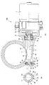
- FIG. 1 is sectional drawing which shows the power steering apparatus which concerns on embodiment of this invention.
- (B) is sectional drawing of the part in which the 2nd bearing in a gear case is accommodated.
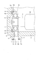
- FIG. 2 is a partially enlarged view of FIG.
- FIG. 3 is a schematic diagram showing a positional relationship between the annular groove and the elongated hole of the gear case.
- the power steering device 100 according to the embodiment of the present invention will be described with reference to the drawings.
- the power steering device 100 is a device that is mounted on a vehicle and assists the steering force applied by the driver to the steering wheel.
- a power steering device 100 includes a worm wheel 1 provided on a steering shaft that is linked to a steering handle, and a worm shaft 2 that is connected to an output shaft 7 a of an electric motor 7 at one end and meshes with the worm wheel 1. Is provided.
- the worm shaft 2 rotates as the electric motor 7 is driven, and the rotation of the worm shaft 2 is decelerated and transmitted to the worm wheel 1.
- the worm wheel 1 and the worm shaft 2 constitute a worm speed reducer.
- the torque output from the electric motor 7 is transmitted from the worm shaft 2 to the worm wheel 1 and applied to the steering shaft as assist torque.
- the torque output by the electric motor 7 corresponds to the steering torque calculated based on the torsion amount of the torsion bar that is twisted by the relative rotation between the input shaft and the output shaft constituting the steering shaft.
- the worm shaft 2 is accommodated in a metal gear case 3.
- a part of the worm shaft 2 is formed with a tooth part 2 a that meshes with the tooth part 1 a of the worm wheel 1.
- An opening 3c is formed on the inner peripheral surface of the gear case 3 at a position corresponding to the tooth 2a, and the tooth 2a of the worm shaft 2 and the tooth 1a of the worm wheel 1 mesh with each other through the opening 3c.
- the base end side which is the electric motor 7 side of the worm shaft 2 is rotatably supported by the first bearing 4.
- the first bearing 4 has a ball interposed between an annular inner ring and an outer ring.
- the outer ring of the first bearing 4 is sandwiched between a step 3 a formed in the gear case 3 and the lock nut 5.
- the inner ring of the first bearing 4 is sandwiched between the step 2b of the worm shaft 2 and the joint 6 press-fitted into the outer periphery of the worm shaft 2. Thereby, the movement to the axial direction of the worm shaft 2 is controlled.
- the distal end side of the worm shaft 2 is freely rotatable by a second bearing 11 housed on the bottom of the gear case 3 via an L-shaped ring 10 as an annular elastic member having an L-shaped cross section.
- Supported by The second bearing 11 has a ball interposed between an annular inner ring and an outer ring.
- a step 2c formed near the tip of the worm shaft 2 is locked to the inner ring of the second bearing 11.
- the backlash in the axial direction of the second bearing 11 is reduced. That is, the L-shaped ring 10 is compressed between the bottom portion of the gear case 3 and the bottom portion of the second bearing 11 to pressurize the second bearing 11 in the axial direction.
- a flange portion 17 having a flat end surface 17a is formed on the outer peripheral surface of the gear case 3 on the end side.
- a through hole 13 is formed in the flange portion 17, and an opening portion of the through hole 13 that opens to the inner peripheral surface of the gear case 3 is formed facing the outer peripheral surface of the second bearing 11.
- a coil spring 12 as an urging member is accommodated in the through hole 13, and the opening of the through hole 13 that opens to the end surface 17 a of the flange portion 17 is closed by a plug 14 having a head portion 14 a.
- An O-ring 16 is interposed between the end surface 17a of the flange portion 17 and the head portion 14a of the plug 14, and the plug 14 is pressed against the end surface 17a of the flange portion 17 by the head portion 14a. Press fit. Instead of press-fitting the plug 14 into the through hole 13, a hexagon bolt may be screwed into the through hole 13 and fastened.
- the coil spring 12 is accommodated in the through hole 13 in a compressed state between the distal end surface of the plug 14 and the outer peripheral surface of the second bearing 11, and the tooth portion 2 a of the worm shaft 2 and the teeth of the worm wheel 1.
- the second bearing 11 is biased in the direction in which the gap with the portion 1a is reduced. That is, the coil spring 12 biases the worm shaft 2 toward the worm wheel 1 via the second bearing 11.
- the inner peripheral surface 3 b surrounding the outer peripheral surface of the second bearing 11 in the gear case 3 is formed so that the second bearing 11 can move toward the worm wheel 1 by the biasing force of the coil spring 12. Specifically, it is formed in a long hole shape. Below, the long hole of the internal peripheral surface 3b is demonstrated in detail with reference to FIG.
- the inner peripheral surface 3b includes a first semicircular arc surface 20 centered on the central axis X of the worm shaft 2 when the first bearing 4 and the second bearing 11 are concentric, and both ends of the first semicircular arc surface 20 And a pair of planes 21 parallel to the urging direction of the coil spring 12 and a slotted hole shape comprising a second semicircular arc surface 22 connected to the plane 21 and symmetrical to the first semicircular arc surface 20 via the plane 21. Formed.
- the inner peripheral surface 3b is formed so that the second bearing 11 can move toward the worm wheel 1 from the concentric state with the first bearing 4 by the biasing force of the coil spring 12.
- the center of the first semicircular arc surface 20 of the inner peripheral surface 3b may be offset from the central axis X toward the coil spring 12 side.
- the L-shaped ring 10 includes an annular first elastic portion 10 a disposed between the bottom portion of the gear case 3 and the bottom portion of the second bearing 11, an inner peripheral surface 3 b of the gear case 3, and a second shape. And an annular second elastic portion 10b disposed between the outer peripheral surface of the bearing 11 and the second elastic portion 10b.
- a first annular groove 31 in which the first elastic part 10a is accommodated is formed at the bottom of the gear case 3, and a second annular groove 32 in which the second elastic part 10b is accommodated is formed in the inner peripheral surface 3b of the gear case 3.
- the L-shaped ring 10 is accommodated in the first annular groove 31 and the second annular groove 32, thereby preventing the L-shaped ring 10 from being displaced in the gear case 3.
- the depth dimension of the first annular groove 31 and the second annular groove 32 is smaller than the thickness of the first elastic part 10a and the second elastic part 10b. Accordingly, the first elastic portion 10a and the second elastic portion 10b protrude from the bottom portion of the gear case 3 and the inner peripheral surface 3b by a predetermined height while being accommodated in the first annular groove 31 and the second annular groove 32, respectively. This protruding portion contacts the second bearing 11, and the second bearing 11 is prevented from contacting the bottom portion of the gear case 3 and the inner peripheral surface 3b.
- a groove 10c for releasing the corner of the outer ring of the second bearing 11 is formed at the boundary between the first elastic portion 10a and the second elastic portion 10b.
- the groove portion 10c also has an effect of absorbing deformation of the L-shaped ring 10.
- the second annular groove 32 is provided with its center Y offset from the central axis X of the worm shaft 2 by a predetermined length D toward the worm wheel 1 side.
- the length D of the offset is set to be the same as the length of the flat surface 21 of the long hole in the inner peripheral surface 3b. That is, the center Y of the second annular groove 32 is set to be the same as the center of the second semicircular arc surface 22 of the long hole.
- the second bearing 11 when the second bearing 11 is pressed by the urging force of the coil spring 12 and is positioned concentrically with the center Y of the second annular groove 32, as shown in FIG. In the direction in which the second bearing 11 moves against the urging force of the coil spring 12, the second bearing 11 has a compressible allowance for the length T.
- the L-shaped ring 10 is accommodated in the first annular groove 31 and the second annular groove 32 of the gear case 3.
- the second bearing 11 is inserted into the gear case 3 and inserted into the inner periphery of the second elastic portion 10b of the L-shaped ring 10.
- the coil spring 12 is accommodated in the through hole 13
- the plug 14 is press-fitted into the through hole 13
- the coil spring 12 is compressed between the outer peripheral surface of the second bearing 11 and the plug 14.
- the worm shaft 2 is inserted into the gear case 3 and the tip of the worm shaft 2 is inserted into the inner circumference of the inner ring of the second bearing 11. Thereby, the assembly of the worm shaft 2 into the gear case 3 is completed.
- the second bearing 11 When the assembly of the worm shaft 2 into the gear case 3 is completed, the second bearing 11 is urged toward the worm wheel 1 by the urging force of the coil spring 12, and there is no backlash. In this state, the center of the second bearing 11 is slightly shifted from the central axis X toward the worm wheel 1 side. Specifically, the center of the second bearing 11 is located between the central axis X and the center Y (see FIG. 3). Therefore, the worm shaft 2 is slightly tilted by the urging force of the coil spring 12.
- first elastic portion 10a of the L-shaped ring 10 is compressed between the bottom portion of the gear case 3 and the bottom portion of the second bearing 11, and presses the second bearing 11 against the step portion 2c of the worm shaft 2. Thereby, the backlash in the axial direction of the second bearing 11 is reduced.
- the first elastic portion 10 a disposed between the bottom of the gear case 3 and the bottom of the second bearing 11, and between the inner peripheral surface 3 b of the gear case 3 and the outer peripheral surface of the second bearing 11.
- the case where the L-shaped ring 10 integrated with the second elastic portion 10b to be arranged has been described.
- the first elastic portion 10a and the second elastic portion 10b are configured by separate elastic members, for example, O-rings, the same effects as those of the above-described embodiment can be obtained.
- the present invention can be applied to a power steering device that assists a steering force applied by a driver to a steering wheel.
Landscapes
- Engineering & Computer Science (AREA)
- General Engineering & Computer Science (AREA)
- Mechanical Engineering (AREA)
- Chemical & Material Sciences (AREA)
- Combustion & Propulsion (AREA)
- Transportation (AREA)
- Power Steering Mechanism (AREA)
- Gear Transmission (AREA)
- Support Of The Bearing (AREA)
Abstract
ウォームシャフトの基端側及び先端側をそれぞれ回転自在に支持する第1軸受及び第2軸受と、第2軸受の外周面に付勢力を付与する付勢部材と、ギヤケースの内周面と第2軸受の外周面との間に配置される弾性部材とを備える。ギヤケースにおける第2軸受の外周面を囲う内周面は、第2軸受が付勢部材の付勢力によってウォームホイールに向けて移動できるように形成され、ギヤケースの内周面には弾性部材が収容される環状溝が形成され、環状溝の中心は第1軸受と第2軸受とが同心状態である場合のウォームシャフトの中心軸からウォームホイール側へオフセットして設けられる。
Description
本発明は、パワーステアリング装置に関するものである。
従来のパワーステアリング装置として、JP3-112784Aには、操舵軸に設けられたウォームホイールと噛み合うウォームシャフトの軸受をスプリングにて付勢することによって、ウォームホイールとウォームシャフトとの歯の隙間を調整するものが知られている(例えば、特許文献1参照)。
JP3-112784Aに開示のパワーステアリング装置では、車輪側からスプリングの付勢力を超える荷重が入力された場合には、スプリングが圧縮されてベアリングがハウジングの内周に当たり、メタルタッチ音が発生する。
本発明は、上記の問題点に鑑みてなされたものであり、軸受とギヤケースとのメタルタッチ音の発生を低減できるパワーステアリング装置を提供することを目的とする。
本発明のある態様によれば、ドライバーが操舵ハンドルに加える操舵力を補助するパワーステアリング装置であって、操舵ハンドルに連係する操舵軸に設けられるウォームホイールと、前記ウォームホイールに噛み合い、電動モータの駆動に伴って回転するウォームシャフトと、前記ウォームシャフトの基端側を回転自在に支持する第1軸受と、前記ウォームシャフトの先端側を回転自在に支持する第2軸受と、前記ウォームシャフトを収容するギヤケースと、前記第2軸受の外周面に付勢力を付与することによって前記ウォームシャフトを前記ウォームホイールに向けて付勢する付勢部材と、前記ギヤケースの内周面と前記第2軸受の外周面との間に配置される弾性部材と、を備え、前記ギヤケースにおける前記第2軸受の外周面を囲う内周面は、前記第2軸受が前記付勢部材の付勢力によって前記ウォームホイールに向けて移動できるように形成され、前記ギヤケースの前記内周面には前記弾性部材が収容される環状溝が形成され、当該環状溝の中心は前記第1軸受と前記第2軸受とが同心状態である場合の前記ウォームシャフトの中心軸から前記ウォームホイール側へオフセットして設けられるパワーステアリング装置が提供される。
本発明の実施形態及び利点については、添付された図面を参照しながら以下に詳細に説明する。
図面を参照して、本発明の実施の形態に係るパワーステアリング装置100について説明する。
パワーステアリング装置100は、車両に搭載され、ドライバーが操舵ハンドルに加える操舵力を補助する装置である。
図1に示すように、パワーステアリング装置100は、操舵ハンドルに連係する操舵軸に設けられるウォームホイール1と、一端部に電動モータ7の出力軸7aが連結されウォームホイール1に噛み合うウォームシャフト2とを備える。電動モータ7の駆動に伴ってウォームシャフト2が回転し、ウォームシャフト2の回転が減速してウォームホイール1に伝達される。ウォームホイール1とウォームシャフト2にてウォーム減速機が構成される。
電動モータ7から出力されたトルクは、ウォームシャフト2からウォームホイール1に伝達されて操舵軸にアシストトルクとして付与される。電動モータ7が出力するトルクは、操舵軸を構成する入力軸と出力軸との相対回転によって捩れるトーションバーの捩れ量に基づいて演算される操舵トルクに対応する。
ウォームシャフト2は金属製のギヤケース3に収容される。ウォームシャフト2の一部には、ウォームホイール1の歯部1aと噛み合う歯部2aが形成される。ギヤケース3の内周面には歯部2aに対応する位置に開口部3cが形成され、その開口部3cを通じてウォームシャフト2の歯部2aとウォームホイール1の歯部1aとが噛み合う。
ウォームシャフト2の電動モータ7側である基端側は、第1軸受4によって回転自在に支持される。第1軸受4は、環状の内輪と外輪の間にボールが介在されたものである。第1軸受4の外輪は、ギヤケース3に形成された段部3aとロックナット5との間で挟持される。第1軸受4の内輪は、ウォームシャフト2の段部2bとウォームシャフト2の外周に圧入されたジョイント6との間で挟持される。これにより、ウォームシャフト2の軸方向への移動が規制される。
図2に示すように、ウォームシャフト2の先端側は、断面がL字状の環状の弾性部材としてのL字リング10を介してギヤケース3の底部に収装された第2軸受11によって回転自在に支持される。第2軸受11は、環状の内輪と外輪の間にボールが介在されたものである。第2軸受11の内輪にはウォームシャフト2の先端部付近に形成された段部2cが係止される。
第2軸受11はL字リング10の付勢力によってウォームシャフト2の段部2cに押し付けられるため、第2軸受11の軸方向のガタつきが低減される。つまり、L字リング10は、ギヤケース3の底部と第2軸受11の底部との間にて圧縮され、第2軸受11を軸方向に与圧している。
ギヤケース3の端部側の外周面には、端面17aが平面状のフランジ部17が突出して形成される。フランジ部17には貫通孔13が形成され、ギヤケース3の内周面に開口する貫通孔13の開口部は、第2軸受11の外周面に臨んで形成される。貫通孔13内には付勢部材としてのコイルスプリング12が収装され、フランジ部17の端面17aに開口する貫通孔13の開口部は頭部14aを有するプラグ14によって閉塞される。
フランジ部17の端面17aとプラグ14の頭部14aとの間にはOリング16が介装され、プラグ14は、頭部14aにてOリング16がフランジ部17の端面17aに対して押し付けられるまで圧入される。なお、プラグ14を貫通孔13内に圧入する代わりに、六角ボルトを貫通孔13内に螺合させて締結するようにしてもよい。
コイルスプリング12は、プラグ14の先端面と第2軸受11の外周面との間にて圧縮された状態で貫通孔13内に収装され、ウォームシャフト2の歯部2aとウォームホイール1の歯部1aとの隙間が小さくなる方向に第2軸受11を付勢する。つまり、コイルスプリング12は、第2軸受11を介してウォームシャフト2をウォームホイール1に向けて付勢する。
ギヤケース3における第2軸受11の外周面を囲う内周面3bは、第2軸受11がコイルスプリング12の付勢力によってウォームホイール1に向けて移動できるように形成される。具体的には、長穴形状に形成される。以下に、内周面3bの長穴について、図3を参照して詳しく説明する。
内周面3bは、第1軸受4と第2軸受11とが同心状態である場合のウォームシャフト2の中心軸Xを中心とする第1半円弧面20と、第1半円弧面20の両端に連接しコイルスプリング12の付勢方向と平行な一対の平面21と、平面21に連接し平面21を介して第1半円弧面20と対称な第2半円弧面22とからなる長穴形状に形成される。このように、内周面3bは、第2軸受11が第1軸受4との同心状態からコイルスプリング12の付勢力によってウォームホイール1に向けて移動できるように形成される。なお、内周面3bの第1半円弧面20の中心を中心軸Xからコイルスプリング12側にオフセットして形成するようにしてもよい。
次に、L字リング10について詳しく説明する。
図2に示すように、L字リング10は、ギヤケース3の底部と第2軸受11の底部との間に配置される環状の第1弾性部10aと、ギヤケース3の内周面3bと第2軸受11の外周面との間に配置される環状の第2弾性部10bとを備える。ギヤケース3の底部には第1弾性部10aが収容される第1環状溝31が形成され、ギヤケース3の内周面3bには第2弾性部10bが収容される第2環状溝32が形成される。L字リング10が第1環状溝31及び第2環状溝32に収容されることによって、ギヤケース3内でのL字リング10の位置ずれが防止される。
第1環状溝31及び第2環状溝32の深さの寸法は、第1弾性部10a及び第2弾性部10bの厚さと比較して小さい。したがって、第1弾性部10a及び第2弾性部10bは、第1環状溝31及び第2環状溝32に収容された状態で、それぞれギヤケース3の底部及び内周面3bから所定高さ突出する。この突出した部分が第2軸受11に当接し、第2軸受11がギヤケース3の底部及び内周面3bに当接することが防止される。
第1弾性部10aと第2弾性部10bの境目には、第2軸受11の外輪の角部を逃がすための溝部10cが形成される。溝部10cは、L字リング10の変形を吸収する効果も有する。
図3に示すように、第2環状溝32は、その中心Yがウォームシャフト2の中心軸Xからウォームホイール1側へ所定長さDだけオフセットして設けられる。具体的には、オフセットの長さDは、内周面3bの長穴の平面21の長さと同一に設定される。つまり、第2環状溝32の中心Yは、長穴の第2半円弧面22の中心と同一に設定される。
これにより、第2軸受11がコイルスプリング12の付勢力によって押圧されて第2環状溝32の中心Yと同心状態に位置する場合には、図3に示すように、第2弾性部10bは、第2軸受11がコイルスプリング12の付勢力に抗して移動する方向に、長さT分の圧縮可能代を有することになる。
次に、ギヤケース3内へのウォームシャフト2の組み付け、及びL字リング10の作用について説明する。
まず、ギヤケース3の第1環状溝31及び第2環状溝32にL字リング10を収容する。
次に、第2軸受11をギヤケース3内に挿入して、L字リング10の第2弾性部10bの内周に挿入する。
次に、貫通孔13内にコイルスプリング12を収装し、貫通孔13にプラグ14を圧入し、コイルスプリング12を第2軸受11の外周面とプラグ14との間で圧縮する。
最後に、ウォームシャフト2をギヤケース3内に挿入して、ウォームシャフト2の先端部を第2軸受11の内輪の内周に挿入する。これにより、ギヤケース3内へのウォームシャフト2の組み付けが完了する。
ギヤケース3内へのウォームシャフト2の組み付けが完了した時点では、第2軸受11は、コイルスプリング12の付勢力によってウォームホイール1側に付勢され、バックラッシュがない状態となる。この状態では、第2軸受11の中心は中心軸Xからウォームホイール1側に僅かにずれた状態となる。具体的には、第2軸受11の中心は中心軸Xと中心Yとの間に位置する(図3参照)。したがって、ウォームシャフト2は、コイルスプリング12の付勢力によって僅かに傾いた状態となる。
パワーステアリング装置100の駆動に伴ってウォームシャフト2とウォームホイール1の歯部1a,2aの摩耗が進む。しかし、その場合には、コイルスプリング12の付勢力によって第2軸受11がギヤケース3の長穴内を移動することによって、ウォームシャフト2とウォームホイール1との歯部1a,2aのバックラッシュが低減される。したがって、パワーステアリング装置100の駆動に伴ってウォームシャフト2とウォームホイール1の歯部1a,2aの摩耗が進めば、第2弾性部10bの圧縮可能代が次第に大きくなることになる。
このような状況で、車輪側からコイルスプリング12の付勢力を超える荷重が入力された場合には、第2軸受11はコイルスプリング12の付勢力に抗して勢いよく移動することになる。しかし、第2軸受11は第2弾性部10bの圧縮可能代を圧縮しながら長穴内を移動するため、第2軸受11がギヤケース3の内周面3bに勢いよく当たることが防止される。したがって、第2軸受11とギヤケース3の内周面3bとの当たりによるメタルタッチ音の発生を低減することができる。
また、L字リング10の第1弾性部10aは、ギヤケース3の底部と第2軸受11の底部との間にて圧縮され、第2軸受11をウォームシャフト2の段部2cに押し付けている。これにより、第2軸受11の軸方向のガタつきが低減される。
以下に、上記実施の形態の変形例について説明する。
上記実施の形態では、ギヤケース3の底部と第2軸受11の底部との間に配置される第1弾性部10aと、ギヤケース3の内周面3bと第2軸受11の外周面との間に配置される第2弾性部10bとが一体であるL字リング10を用いる場合について説明した。しかし、この構成に代わり、第1弾性部10aと第2弾性部10bとを別々の弾性部材、例えばOリングにて構成するようにしても、上記実施の形態と同様の作用効果を奏する。
以上、本発明の実施形態について説明したが、上記実施形態は本発明の適用例の一部を示したに過ぎず、本発明の技術的範囲を上記実施形態の具体的構成に限定する趣旨ではない。
本願は2011年3月22日に日本国特許庁に出願された特願2011-62369に基づく優先権を主張し、この出願の全ての内容は参照により本明細書に組み込まれる。
本発明は、ドライバーがハンドルに加える操舵力を補助するパワーステアリング装置に適用することができる。
Claims (4)
- ドライバーが操舵ハンドルに加える操舵力を補助するパワーステアリング装置であって、
操舵ハンドルに連係する操舵軸に設けられるウォームホイールと、
前記ウォームホイールに噛み合い、電動モータの駆動に伴って回転するウォームシャフトと、
前記ウォームシャフトの基端側を回転自在に支持する第1軸受と、
前記ウォームシャフトの先端側を回転自在に支持する第2軸受と、
前記ウォームシャフトを収容するギヤケースと、
前記第2軸受の外周面に付勢力を付与することによって前記ウォームシャフトを前記ウォームホイールに向けて付勢する付勢部材と、
前記ギヤケースの内周面と前記第2軸受の外周面との間に配置される弾性部材と、を備え、
前記ギヤケースにおける前記第2軸受の外周面を囲う内周面は、前記第2軸受が前記付勢部材の付勢力によって前記ウォームホイールに向けて移動できるように形成され、
前記ギヤケースの前記内周面には前記弾性部材が収容される環状溝が形成され、当該環状溝の中心は前記第1軸受と前記第2軸受とが同心状態である場合の前記ウォームシャフトの中心軸から前記ウォームホイール側へオフセットして設けられるパワーステアリング装置。 - 請求項1に記載のパワーステアリング装置であって、
前記弾性部材は、前記ギヤケースの底部と前記第2軸受の底部との間に配置される環状の第1弾性部と、前記ギヤケースの内周面と前記第2軸受の外周面との間に配置される環状の第2弾性部と、を備える断面L字状のL字リングであるパワーステアリング装置。 - 請求項1に記載のパワーステアリング装置であって、
前記ギヤケースの内周面は、前記ウォームシャフトの前記中心軸を中心とする第1半円弧面と、前記付勢部材の付勢方向と平行な一対の平面と、前記平面を介して前記第1半円弧面と対称な第2半円弧面と、からなり、
前記環状溝の中心は、前記第2半円弧面の中心と略同一であるパワーステアリング装置。 - 請求項2に記載のパワーステアリング装置であって、
前記第2軸受は、外周面に作用する前記付勢部材及び前記第2弾性部の付勢力によって前記ウォームホイールに向けて付勢されるパワーステアリング装置。
Priority Applications (4)
| Application Number | Priority Date | Filing Date | Title |
|---|---|---|---|
| ES12760118.5T ES2625610T3 (es) | 2011-03-22 | 2012-02-14 | Dispositivo de dirección asistida |
| CN201280013820.3A CN103442965B (zh) | 2011-03-22 | 2012-02-14 | 动力转向装置 |
| EP12760118.5A EP2689987B1 (en) | 2011-03-22 | 2012-02-14 | Power steering device |
| US14/006,075 US9033096B2 (en) | 2011-03-22 | 2012-02-14 | Power steering device |
Applications Claiming Priority (2)
| Application Number | Priority Date | Filing Date | Title |
|---|---|---|---|
| JP2011062369A JP6130988B2 (ja) | 2011-03-22 | 2011-03-22 | パワーステアリング装置 |
| JP2011-062369 | 2011-03-22 |
Publications (1)
| Publication Number | Publication Date |
|---|---|
| WO2012127935A1 true WO2012127935A1 (ja) | 2012-09-27 |
Family
ID=46879099
Family Applications (1)
| Application Number | Title | Priority Date | Filing Date |
|---|---|---|---|
| PCT/JP2012/053359 Ceased WO2012127935A1 (ja) | 2011-03-22 | 2012-02-14 | パワーステアリング装置 |
Country Status (6)
| Country | Link |
|---|---|
| US (1) | US9033096B2 (ja) |
| EP (1) | EP2689987B1 (ja) |
| JP (1) | JP6130988B2 (ja) |
| CN (1) | CN103442965B (ja) |
| ES (1) | ES2625610T3 (ja) |
| WO (1) | WO2012127935A1 (ja) |
Cited By (4)
| Publication number | Priority date | Publication date | Assignee | Title |
|---|---|---|---|---|
| WO2013110575A1 (de) * | 2012-01-23 | 2013-08-01 | Zf Lenksysteme Gmbh | Servogetriebe für eine hilfskraftlenkung |
| CN104210530A (zh) * | 2013-05-28 | 2014-12-17 | 株式会社万都 | 电力转向装置的减速器 |
| CN104340263A (zh) * | 2013-08-07 | 2015-02-11 | 现代摩比斯株式会社 | 消声装置 |
| CN106194621A (zh) * | 2016-08-17 | 2016-12-07 | 王玉多 | 惯性推动杠杆发电 |
Families Citing this family (20)
| Publication number | Priority date | Publication date | Assignee | Title |
|---|---|---|---|---|
| JP5551642B2 (ja) * | 2011-03-22 | 2014-07-16 | カヤバ工業株式会社 | パワーステアリング装置 |
| JP5778123B2 (ja) * | 2012-12-25 | 2015-09-16 | 日立オートモティブシステムズステアリング株式会社 | パワーステアリング装置及びバックラッシュ調整機構 |
| KR101477907B1 (ko) * | 2013-05-29 | 2014-12-30 | 주식회사 만도 | 전동식 동력 보조 조향장치의 감속기 |
| JP6129774B2 (ja) * | 2014-03-24 | 2017-05-17 | 株式会社ショーワ | パワーステアリング装置 |
| JP6118750B2 (ja) * | 2014-03-26 | 2017-04-19 | 株式会社ショーワ | ウォーム付勢構造体 |
| DE102014107073A1 (de) * | 2014-05-20 | 2015-11-26 | Robert Bosch Automotive Steering Gmbh | Lenkgetriebe |
| CN106458249B (zh) * | 2014-06-27 | 2019-01-18 | 三菱电机株式会社 | 一体型电动助力转向装置及其制造方法 |
| JP6108358B2 (ja) * | 2014-07-23 | 2017-04-05 | 株式会社ショーワ | ウォーム付勢構造体 |
| JP6458982B2 (ja) * | 2014-09-08 | 2019-01-30 | 株式会社ジェイテクト | ウォーム減速機 |
| JP2016112955A (ja) * | 2014-12-12 | 2016-06-23 | 日立オートモティブシステムズステアリング株式会社 | パワーステアリング装置 |
| JP6167198B1 (ja) | 2016-03-25 | 2017-07-19 | Kyb株式会社 | 電動パワーステアリング装置及び電動パワーステアリング装置の製造方法 |
| DE102016211706B3 (de) * | 2016-06-29 | 2017-12-14 | Ford Global Technologies, Llc | Getriebeeinheit für ein Kraftfahrzeug |
| DE102016211694B3 (de) * | 2016-06-29 | 2017-10-05 | Ford Global Technologies, Llc | Getriebeeinheit für ein Kraftfahrzeug |
| JP6876249B2 (ja) * | 2017-04-19 | 2021-05-26 | 株式会社ジェイテクト | ウォーム減速機および電動パワーステアリング装置 |
| JP6975379B2 (ja) | 2017-08-07 | 2021-12-01 | 株式会社ジェイテクト | ウォーム減速機 |
| JP6875962B2 (ja) * | 2017-08-31 | 2021-05-26 | Kyb株式会社 | パワーステアリング装置 |
| US20190101206A1 (en) * | 2017-09-29 | 2019-04-04 | Kinematics, Llc | Integrated slew drive |
| KR101993295B1 (ko) * | 2017-12-19 | 2019-06-26 | 주식회사 만도 | 전동식 동력 보조 조향장치의 감속기 |
| KR20190105931A (ko) * | 2018-03-07 | 2019-09-18 | 삼성전자주식회사 | 기어 소음 저감장치 및 이를 포함하는 전자장치 |
| JP7280763B2 (ja) * | 2019-06-27 | 2023-05-24 | Kyb株式会社 | ウォームシャフト、ウォーム減速機及びウォームシャフトの製造方法 |
Citations (5)
| Publication number | Priority date | Publication date | Assignee | Title |
|---|---|---|---|---|
| JPH03112784A (ja) | 1989-09-27 | 1991-05-14 | Mazda Motor Corp | 車両の後輪操舵装置 |
| JP2003154945A (ja) * | 2001-11-20 | 2003-05-27 | Koyo Seiko Co Ltd | 電動式動力舵取装置 |
| JP2006088775A (ja) * | 2004-09-21 | 2006-04-06 | Favess Co Ltd | 電動パワーステアリング装置 |
| JP2007216729A (ja) * | 2006-02-14 | 2007-08-30 | Jtekt Corp | 電動パワーステアリング装置 |
| JP2008095839A (ja) * | 2006-10-12 | 2008-04-24 | Jtekt Corp | 転がり軸受装置および密封装置 |
Family Cites Families (13)
| Publication number | Priority date | Publication date | Assignee | Title |
|---|---|---|---|---|
| DE19811977A1 (de) * | 1998-03-19 | 1999-09-30 | Mannesmann Vdo Ag | Schneckengetriebe |
| FR2808759B1 (fr) * | 2000-05-10 | 2005-08-26 | Koyo Seiko Co | Appareil de direction assistee electrique |
| JP3646205B2 (ja) * | 2000-09-04 | 2005-05-11 | 光洋精工株式会社 | 電動パワーステアリング装置 |
| JP2004249844A (ja) * | 2003-02-20 | 2004-09-09 | Koyo Seiko Co Ltd | 電動パワーステアリング装置 |
| JP4716679B2 (ja) * | 2003-06-25 | 2011-07-06 | 日本精工株式会社 | ウォーム減速機及び電動式パワーステアリング装置 |
| JP4385286B2 (ja) * | 2004-01-29 | 2009-12-16 | 株式会社ジェイテクト | 電動パワーステアリング装置 |
| JP4356485B2 (ja) * | 2004-03-09 | 2009-11-04 | 株式会社ジェイテクト | 電動パワーステアリング装置 |
| JP2005299837A (ja) * | 2004-04-14 | 2005-10-27 | Koyo Seiko Co Ltd | 転がり軸受装置 |
| JP4501068B2 (ja) * | 2004-10-14 | 2010-07-14 | 株式会社ジェイテクト | 電動パワーステアリング装置 |
| JP5039036B2 (ja) * | 2006-07-12 | 2012-10-03 | 日立オートモティブシステムズ株式会社 | パワーステアリング装置と、減速機構及び軸受ホルダ |
| JP5336823B2 (ja) * | 2008-11-14 | 2013-11-06 | カヤバ工業株式会社 | ウォーム減速機及び電動パワーステアリング装置 |
| JP4866931B2 (ja) * | 2009-03-24 | 2012-02-01 | 日立オートモティブシステムズ株式会社 | パワーステアリング装置 |
| JP5048804B2 (ja) * | 2010-03-31 | 2012-10-17 | 日立オートモティブシステムズ株式会社 | パワーステアリング装置 |
-
2011
- 2011-03-22 JP JP2011062369A patent/JP6130988B2/ja active Active
-
2012
- 2012-02-14 US US14/006,075 patent/US9033096B2/en not_active Expired - Fee Related
- 2012-02-14 EP EP12760118.5A patent/EP2689987B1/en not_active Not-in-force
- 2012-02-14 ES ES12760118.5T patent/ES2625610T3/es active Active
- 2012-02-14 CN CN201280013820.3A patent/CN103442965B/zh not_active Expired - Fee Related
- 2012-02-14 WO PCT/JP2012/053359 patent/WO2012127935A1/ja not_active Ceased
Patent Citations (5)
| Publication number | Priority date | Publication date | Assignee | Title |
|---|---|---|---|---|
| JPH03112784A (ja) | 1989-09-27 | 1991-05-14 | Mazda Motor Corp | 車両の後輪操舵装置 |
| JP2003154945A (ja) * | 2001-11-20 | 2003-05-27 | Koyo Seiko Co Ltd | 電動式動力舵取装置 |
| JP2006088775A (ja) * | 2004-09-21 | 2006-04-06 | Favess Co Ltd | 電動パワーステアリング装置 |
| JP2007216729A (ja) * | 2006-02-14 | 2007-08-30 | Jtekt Corp | 電動パワーステアリング装置 |
| JP2008095839A (ja) * | 2006-10-12 | 2008-04-24 | Jtekt Corp | 転がり軸受装置および密封装置 |
Non-Patent Citations (1)
| Title |
|---|
| See also references of EP2689987A4 * |
Cited By (5)
| Publication number | Priority date | Publication date | Assignee | Title |
|---|---|---|---|---|
| WO2013110575A1 (de) * | 2012-01-23 | 2013-08-01 | Zf Lenksysteme Gmbh | Servogetriebe für eine hilfskraftlenkung |
| CN104210530A (zh) * | 2013-05-28 | 2014-12-17 | 株式会社万都 | 电力转向装置的减速器 |
| CN104340263A (zh) * | 2013-08-07 | 2015-02-11 | 现代摩比斯株式会社 | 消声装置 |
| CN104340263B (zh) * | 2013-08-07 | 2018-02-06 | 现代摩比斯株式会社 | 消声装置 |
| CN106194621A (zh) * | 2016-08-17 | 2016-12-07 | 王玉多 | 惯性推动杠杆发电 |
Also Published As
| Publication number | Publication date |
|---|---|
| US20140008142A1 (en) | 2014-01-09 |
| JP6130988B2 (ja) | 2017-05-17 |
| CN103442965B (zh) | 2016-06-15 |
| CN103442965A (zh) | 2013-12-11 |
| EP2689987A1 (en) | 2014-01-29 |
| JP2012197029A (ja) | 2012-10-18 |
| EP2689987A4 (en) | 2015-07-22 |
| US9033096B2 (en) | 2015-05-19 |
| EP2689987B1 (en) | 2017-04-19 |
| ES2625610T3 (es) | 2017-07-20 |
Similar Documents
| Publication | Publication Date | Title |
|---|---|---|
| JP6130988B2 (ja) | パワーステアリング装置 | |
| US8684127B2 (en) | Electric power steering system | |
| JP5645070B2 (ja) | 電動パワーステアリング装置 | |
| JP4482349B2 (ja) | ウォームギヤ機構及びウォームギヤ機構を搭載した電動パワーステアリング装置 | |
| JP5609977B2 (ja) | 電動式パワーステアリング装置 | |
| JP6020893B2 (ja) | 電動パワーステアリング装置 | |
| CN104015783B (zh) | 转向角传感器及使用该转向角传感器的电动动力转向装置 | |
| JP4868215B2 (ja) | 電動パワーステアリング装置 | |
| CN101454593A (zh) | 减速装置及配备该减速装置的电动式动力转向装置 | |
| JP6052988B2 (ja) | パワーステアリング装置 | |
| JP5273228B2 (ja) | ラックピニオン式ステアリング装置 | |
| JP2016003760A (ja) | ウォーム減速機およびそれを備えた電動パワーステアリング装置 | |
| JP5120110B2 (ja) | 電動パワーステアリング装置 | |
| JP2009250321A (ja) | 歯車減速装置およびそれを備えた電動パワーステアリング装置 | |
| JP2004345444A (ja) | 電動パワーステアリング装置 | |
| JP2007186021A (ja) | 電動パワーステアリング装置 | |
| JP2012197028A (ja) | パワーステアリング装置 | |
| JP2013086528A (ja) | ラック・アンド・ピニオン式ステアリング装置 | |
| JP2012086799A (ja) | 電動パワーステアリング装置 | |
| JP7322417B2 (ja) | ウォーム減速機 | |
| JP2014193638A (ja) | パワーステアリング装置 | |
| JP2004249767A (ja) | 電動パワーステアリング装置 | |
| JP4400381B2 (ja) | 電動パワーステアリング装置 | |
| JP4400369B2 (ja) | ピニオン・アシスト式電動パワーステアリング装置 | |
| JP7751442B2 (ja) | 電動アシスト装置および電動アシスト装置用ウォームダンパ |
Legal Events
| Date | Code | Title | Description |
|---|---|---|---|
| 121 | Ep: the epo has been informed by wipo that ep was designated in this application |
Ref document number: 12760118 Country of ref document: EP Kind code of ref document: A1 |
|
| DPE1 | Request for preliminary examination filed after expiration of 19th month from priority date (pct application filed from 20040101) | ||
| WWE | Wipo information: entry into national phase |
Ref document number: 14006075 Country of ref document: US |
|
| NENP | Non-entry into the national phase |
Ref country code: DE |
|
| REEP | Request for entry into the european phase |
Ref document number: 2012760118 Country of ref document: EP |
|
| WWE | Wipo information: entry into national phase |
Ref document number: 2012760118 Country of ref document: EP |