WO2012128133A1 - 建設機械 - Google Patents
建設機械 Download PDFInfo
- Publication number
- WO2012128133A1 WO2012128133A1 PCT/JP2012/056485 JP2012056485W WO2012128133A1 WO 2012128133 A1 WO2012128133 A1 WO 2012128133A1 JP 2012056485 W JP2012056485 W JP 2012056485W WO 2012128133 A1 WO2012128133 A1 WO 2012128133A1
- Authority
- WO
- WIPO (PCT)
- Prior art keywords
- insulation resistance
- relay
- electric
- resistance deterioration
- voltage waveform
- Prior art date
- Legal status (The legal status is an assumption and is not a legal conclusion. Google has not performed a legal analysis and makes no representation as to the accuracy of the status listed.)
- Ceased
Links
Images

Classifications
-
- E—FIXED CONSTRUCTIONS
- E02—HYDRAULIC ENGINEERING; FOUNDATIONS; SOIL SHIFTING
- E02F—DREDGING; SOIL-SHIFTING
- E02F9/00—Component parts of dredgers or soil-shifting machines, not restricted to one of the kinds covered by groups E02F3/00 - E02F7/00
- E02F9/08—Superstructures; Supports for superstructures
- E02F9/10—Supports for movable superstructures mounted on travelling or walking gears or on other superstructures
- E02F9/12—Slewing or traversing gears
- E02F9/121—Turntables, i.e. structure rotatable about 360°
- E02F9/123—Drives or control devices specially adapted therefor
-
- G—PHYSICS
- G01—MEASURING; TESTING
- G01R—MEASURING ELECTRIC VARIABLES; MEASURING MAGNETIC VARIABLES
- G01R31/00—Arrangements for testing electric properties; Arrangements for locating electric faults; Arrangements for electrical testing characterised by what is being tested not provided for elsewhere
- G01R31/12—Testing dielectric strength or breakdown voltage ; Testing or monitoring effectiveness or level of insulation, e.g. of a cable or of an apparatus, for example using partial discharge measurements; Electrostatic testing
-
- E—FIXED CONSTRUCTIONS
- E02—HYDRAULIC ENGINEERING; FOUNDATIONS; SOIL SHIFTING
- E02F—DREDGING; SOIL-SHIFTING
- E02F9/00—Component parts of dredgers or soil-shifting machines, not restricted to one of the kinds covered by groups E02F3/00 - E02F7/00
- E02F9/20—Drives; Control devices
-
- E—FIXED CONSTRUCTIONS
- E02—HYDRAULIC ENGINEERING; FOUNDATIONS; SOIL SHIFTING
- E02F—DREDGING; SOIL-SHIFTING
- E02F9/00—Component parts of dredgers or soil-shifting machines, not restricted to one of the kinds covered by groups E02F3/00 - E02F7/00
- E02F9/20—Drives; Control devices
- E02F9/2058—Electric or electro-mechanical or mechanical control devices of vehicle sub-units
- E02F9/2091—Control of energy storage means for electrical energy, e.g. battery or capacitors
-
- E—FIXED CONSTRUCTIONS
- E02—HYDRAULIC ENGINEERING; FOUNDATIONS; SOIL SHIFTING
- E02F—DREDGING; SOIL-SHIFTING
- E02F9/00—Component parts of dredgers or soil-shifting machines, not restricted to one of the kinds covered by groups E02F3/00 - E02F7/00
- E02F9/20—Drives; Control devices
- E02F9/2058—Electric or electro-mechanical or mechanical control devices of vehicle sub-units
- E02F9/2095—Control of electric, electro-mechanical or mechanical equipment not otherwise provided for, e.g. ventilators, electro-driven fans
-
- E—FIXED CONSTRUCTIONS
- E02—HYDRAULIC ENGINEERING; FOUNDATIONS; SOIL SHIFTING
- E02F—DREDGING; SOIL-SHIFTING
- E02F9/00—Component parts of dredgers or soil-shifting machines, not restricted to one of the kinds covered by groups E02F3/00 - E02F7/00
- E02F9/26—Indicating devices
- E02F9/267—Diagnosing or detecting failure of vehicles
-
- G—PHYSICS
- G01—MEASURING; TESTING
- G01R—MEASURING ELECTRIC VARIABLES; MEASURING MAGNETIC VARIABLES
- G01R31/00—Arrangements for testing electric properties; Arrangements for locating electric faults; Arrangements for electrical testing characterised by what is being tested not provided for elsewhere
- G01R31/327—Testing of circuit interrupters, switches or circuit-breakers
-
- G—PHYSICS
- G01—MEASURING; TESTING
- G01R—MEASURING ELECTRIC VARIABLES; MEASURING MAGNETIC VARIABLES
- G01R31/00—Arrangements for testing electric properties; Arrangements for locating electric faults; Arrangements for electrical testing characterised by what is being tested not provided for elsewhere
- G01R31/005—Testing of electric installations on transport means
- G01R31/006—Testing of electric installations on transport means on road vehicles, e.g. automobiles or trucks
-
- G—PHYSICS
- G01—MEASURING; TESTING
- G01R—MEASURING ELECTRIC VARIABLES; MEASURING MAGNETIC VARIABLES
- G01R31/00—Arrangements for testing electric properties; Arrangements for locating electric faults; Arrangements for electrical testing characterised by what is being tested not provided for elsewhere
- G01R31/327—Testing of circuit interrupters, switches or circuit-breakers
- G01R31/3277—Testing of circuit interrupters, switches or circuit-breakers of low voltage devices, e.g. domestic or industrial devices, such as motor protections, relays, rotation switches
- G01R31/3278—Testing of circuit interrupters, switches or circuit-breakers of low voltage devices, e.g. domestic or industrial devices, such as motor protections, relays, rotation switches of relays, solenoids or reed switches
-
- G—PHYSICS
- G01—MEASURING; TESTING
- G01R—MEASURING ELECTRIC VARIABLES; MEASURING MAGNETIC VARIABLES
- G01R31/00—Arrangements for testing electric properties; Arrangements for locating electric faults; Arrangements for electrical testing characterised by what is being tested not provided for elsewhere
- G01R31/50—Testing of electric apparatus, lines, cables or components for short-circuits, continuity, leakage current or incorrect line connections
- G01R31/52—Testing for short-circuits, leakage current or ground faults
Definitions
- the present invention relates to a construction machine, and more particularly to a construction machine having a function of detecting an insulation resistance deterioration between an electric system including a power storage device, an electric motor and the like and a vehicle body.
- a fuel such as gasoline or light oil is used as a power source, and a hydraulic pump is driven by an engine to generate hydraulic pressure to drive a hydraulic actuator such as a hydraulic motor or a hydraulic cylinder.
- Hydraulic actuators are small and light and capable of high output, and are widely used as construction machine actuators.
- Electric motors are more energy efficient than hydraulic actuators and have excellent energy characteristics such as the ability to regenerate kinetic energy during braking as electric energy (in the case of hydraulic actuators, release it as heat).
- Patent Document 1 an embodiment of a hydraulic excavator in which an electric motor is mounted as a drive actuator for a revolving structure is shown.
- Actuators that drive the swing body of a hydraulic excavator to swing with respect to a traveling body are frequently used, and frequently start and stop and accelerate and decelerate repeatedly during work.
- the kinetic energy of the swinging body during deceleration is discarded as heat on the hydraulic circuit in the case of a hydraulic actuator, but in the case of an electric motor, regeneration as electric energy can be expected.
- a relay failure diagnosis device that performs a failure diagnosis of a relay using an insulation resistance deterioration detection device is disclosed (see, for example, Patent Document 3).
- An insulation resistance reduction detector having a self-abnormality diagnosis function with a simple configuration and a self-abnormality diagnosis method are disclosed (for example, see Patent Document 4).
- Patent Document 3 and Prior Art of Patent Document 4 are mainly applied in the field of, for example, an electric vehicle equipped with a high voltage circuit.
- the hybrid construction machine has a limited space for installing an insulation resistance deterioration detection device, etc., so it has all the functions of an insulation resistance deterioration detection function, a relay failure diagnosis function, and a self-abnormality diagnosis function.
- an insulation resistance deterioration detection system that can be configured compactly by realizing these with a simple circuit configuration.
- the present invention has been made based on the above-described matters, and its purpose is a construction including a drive system including an electric motor, an electricity storage device, and a relay for cutting off an electrical connection between the electricity storage device and the drive system.
- a construction machine including an insulation resistance deterioration detection device capable of performing all of insulation resistance deterioration detection, relay failure diagnosis, and self-abnormality diagnosis with a simple circuit configuration.
- a first invention includes an electric motor, a drive system including an electric circuit and a controller for driving and controlling the electric motor, a power storage device, the power storage device, and the drive system.
- the electric system includes a first voltage waveform generator, the storage device side and the first voltage waveform with respect to the relay.
- a first insulation resistance deterioration having a first detector connected to the generator and detecting an insulation resistance deterioration on the power storage device side by measuring a change in the waveform input from the first voltage waveform generator
- a detector, a second voltage waveform generator, and the relay connected to the drive system side and the second voltage waveform generator with respect to the relay;
- a second insulation resistance deterioration detection device and a second detecting section for detecting an insulation resistance deterioration of the driving system side by measuring the change of the input waveform from the generator.
- the second invention is the first invention, wherein the first and second detectors in the first and second insulation resistance deterioration detectors can confirm the normality of the relay. It is characterized in that both voltage waveforms from the second and first voltage waveform generators are electrically connected so as to be able to take in.
- a third invention is characterized in that, in the first invention, the first insulation resistance deterioration detecting device detects an insulation resistance deterioration around the power storage device when the relay is opened.
- the fourth invention is characterized in that, in the first invention, the second insulation resistance deterioration detecting device is connected to both positive and negative electrodes of an electric circuit in the drive system via an impedance element.
- a fifth invention is the first invention, wherein the first and second insulation resistance deterioration detecting devices are disposed on the drive system side with respect to the relay, and the first insulation resistance deterioration detecting device is The drive system side is connected to the electricity storage device side via a cable and another relay.
- insulation resistance deterioration detection can be performed with a simple circuit configuration.
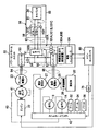
- FIG. 1 is a system configuration diagram of an electric / hydraulic device that constitutes an embodiment of a construction machine according to the present invention. It is an electric circuit diagram of the electric system which constitutes one embodiment of the construction machine of the present invention.
- FIG. 1 is a side view showing an embodiment of a construction machine according to the present invention
- FIG. 2 is a system configuration diagram of electric / hydraulic equipment constituting one embodiment of the construction machine according to the present invention
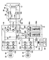
- FIG. 3 is a construction according to the present invention. It is an electric circuit diagram of the electric system which constitutes one embodiment of a machine.
- the hybrid hydraulic excavator includes a traveling body 10, and a revolving body 20 and a shovel mechanism 30 provided on the traveling body 10 so as to be able to swivel.
- the traveling body 10 includes a pair of crawlers 11a and 11b and crawler frames 12a and 12b (only one side is shown in FIG. 1), a pair of traveling hydraulic motors 13 and 14 that independently drive and control the crawlers 11a and 11b, and It consists of a speed reduction mechanism.
- the swing body 20 includes a swing frame 21, an engine 22 as a prime mover provided on the swing frame 21, an assist power generation motor 23 driven by the engine 22, a swing electric motor 25, a swing hydraulic motor 27, and an assist.
- An electric double layer capacitor 24 connected to the generator motor 23 and the swing electric motor 25, a reduction mechanism 26 that decelerates the rotation of the swing electric motor 25 and the swing hydraulic motor 27, and the like.
- the driving force of 27 is transmitted through the speed reduction mechanism 26, and the turning body 20 (the turning frame 21) is driven to turn with respect to the traveling body 10 by the driving force.
- an excavator mechanism (front device) 30 is mounted on the revolving unit 20.
- the shovel mechanism 30 includes a boom 31, a boom cylinder 32 for driving the boom 31, an arm 33 rotatably supported near the tip of the boom 31, and an arm cylinder 34 for driving the arm 33.
- the bucket 35 includes a bucket 35 rotatably supported at the tip of the arm 33, a bucket cylinder 36 for driving the bucket 35, and the like.
- a hydraulic system for driving hydraulic actuators such as the traveling hydraulic motors 13 and 14, the swing hydraulic motor 27, the boom cylinder 32, the arc cylinder 34, and the bucket cylinder 36 described above is provided on the swing frame 21 of the swing body 20.
- the hydraulic system 40 includes a hydraulic pump 41 (FIG. 2) serving as a hydraulic source for generating hydraulic pressure and a control valve 42 (FIG. 2) for driving and controlling each actuator.
- the hydraulic pump 41 is driven by the engine 22.
- the system configuration of the electric / hydraulic equipment of the hydraulic excavator will be outlined.
- the driving force of the engine 22 is transmitted to the hydraulic pump 41.
- the control valve 42 controls the flow rate and direction of the pressure oil supplied to the turning hydraulic motor 27 in accordance with a turning operation command (hydraulic pilot signal) from a turning operation lever device (not shown).
- the control valve 42 is pressure oil supplied to the boom cylinder 32, the arm cylinder 34, the bucket cylinder 36, and the traveling hydraulic motors 13 and 14 in response to an operation command (hydraulic pilot signal) from an operation lever device other than turning. Control the flow rate and direction.
- the electric system includes the above-described assist power generation motor 23, the swing electric motor 25, a power control unit 55 including electric components that drive and control these, and a drive system including a main controller 80, and an electric storage including an electric double layer capacitor 24.
- the main relay 56 which interrupts
- the power control unit 55 constituting the drive system includes a chopper 51, inverters 52 and 53, a smoothing capacitor 54, and the like.
- the main relay 56 includes relays 57A and 57B, a relay 57C that constitutes an inrush current prevention circuit with the resistor 58, and a relay 103 for an insulation resistance deterioration detection device, which will be described later.
- the DC power from the capacitor 24 is boosted to a predetermined bus voltage by the chopper 51 and input to the inverter 52 for driving the swing electric motor 25 and the inverter 53 for driving the assist power generation motor 23.
- the relays 57A and 57B are main contactors, and are provided to cut off the supply of the electric charge of the capacitor 24 to the electric system when the electric system is stopped or abnormal.
- the inrush current prevention circuit constituted by the relay 57C and the resistor 58 supplies a limited current from the path of this circuit before closing the relays 57A and 57B in a state where the capacitor in the chopper 51 is not charged.
- the capacitor is charged.
- the smoothing capacitor 54 is provided to stabilize the bus voltage.
- the rotating shafts of the swing electric motor 25 and the swing hydraulic motor 27 are coupled to drive the swing body 20 via the speed reduction mechanism 26.
- the capacitor 24 is charged / discharged according to the driving state (powering or regenerating) of the assist power generation motor 23 and the swing electric motor 25.
- the capacitor 24 and the main relay 56 are disposed inside a single housing that is a power storage unit 59.
- the main controller 80 generates control commands for the control valve 42 and the power control unit 55 using signals not shown in FIG. 2 such as an operation command signal, a pressure signal, and a rotation speed signal. Switching of the turning mode, turning control of each mode, abnormality monitoring of the electric system, control such as energy management are performed.
- the electromagnetic proportional valve 75 converts an electric signal from the main controller 80 into a hydraulic pilot signal, and the control valve 42 is controlled by this hydraulic pilot signal.
- the electric controller 104 transmits and receives signals to and from the main controller 80, and includes two inverters 52 and 53, a chopper 51, and first and second insulation resistance deterioration detection devices 90A and 90B, which will be described later, built in the power control unit 55. Perform overall control.
- the first and second insulation resistance deterioration detecting devices 90A and 90B are built in the power control unit 55 and connected to the respective electric circuits via the coupled impedance elements 101A to 101C and the first and second detection paths 102A and 102B. .
- reference numerals 91 to 95 are detection sequences for specifying an insulation resistance deterioration portion of the electric controller 104 and portions that can be specified by the first and second insulation resistance deterioration detection devices 90A and 90B.
- 91 is a capacitor 24
- the electric system generally includes a capacitor 24, a main relay 56, a chopper 51, a main smoothing capacitor 54, a swing electric motor 25, a swing electric motor inverter 52, and an assist power generation motor 23. , An assist power generation motor inverter 53, a main controller 80, and insulation resistance deterioration detection devices 90A and 90B.
- the chopper 51 includes a reactor 51a, power transistors (hereinafter referred to as transistors) 51b and 51c such as IGBTs, and a smoothing capacitor 51d as switching elements.
- Reactor 51a has one end connected to the positive electrode of capacitor 24 via relay 57A, and the other end connected to the source of transistor 51b and the drain of transistor 51c.
- the drain of the transistor 51b is connected to one end of the main smoothing capacitor 54, one end of the assist power generation motor inverter 53, and one end of the swing electric motor inverter 52.
- the source of the transistor 51c is connected to the negative electrode of the capacitor 24, the other end of the main smoothing capacitor 54, the assist generator motor inverter 53, and the other end of the swing electric motor inverter 52 via the relay 57B.
- One end of the reactor 51a is connected to one end of a smoothing capacitor 51d, and the other end of the smoothing capacitor 51d is connected to the source of the transistor 51c.
- the electric controller 104 is connected to the gates of the transistors 51b and 51c to perform switching control. In response to a command from the electric controller 104, the two transistors 51b and 51c are alternately opened and closed, thereby boosting the voltage of the capacitor 24 to a bus voltage at which the assist generator motor inverter 53 and the swing electric motor inverter 52 can operate. At the same time, an operation for controlling the bus voltage near a predetermined constant value is performed.
- the main smoothing capacitor 54 smoothes the DC voltage.
- the assist generator motor inverter 53 and the swing electric motor inverter 52 are connected to the chopper 51 and the main smoothing capacitor 54 on one side and to the assist power generation motor 23 and the swing electric motor 25 on the other side, respectively.
- the inverter 53 for the assist generator motor and the inverter 52 for the swing electric motor receive a command from the electric controller 104 using a bridge circuit including six transistors 53A and 52A as switching elements such as IGBTs, for example. Are turned on and off, and the pulse width is changed to generate a three-phase alternating current, and the assist generator motor 23 and the swing electric motor 25 are driven.
- the assist generator motor 23 and the power control unit 55 are connected by a cable 94 via a connector 122.
- the swing electric motor 25 and the power control unit 55 are connected by a cable 95 via a connector 123.
- the power control unit 55 and the power storage unit 59 are connected by a cable 92 and a cable 101D via connectors 120 and 121.
- the first insulation resistance deterioration detecting device 90A includes a first voltage waveform generating device 100A that generates an alternating current or pulse waveform, and a first portion connected to a predetermined part of an electric circuit of the electric system to apply the alternating current or pulse waveform.
- the amplitude level and waveform of the input signal are measured via the detection path 102A and the first detection path 102A, the generated signal and the measurement signal are compared, and the insulation resistance value for the body frame of the target circuit is calculated and set in advance.
- the first detection unit 99A that detects the presence or absence of insulation resistance deterioration by comparing with the set value.
- the second insulation resistance deterioration detecting device 90B is connected to a second voltage waveform generating device 100B that generates an alternating current or pulse waveform and a predetermined part of an electric circuit of the electric system for applying the alternating current or pulse waveform.
- the amplitude level and waveform of the input signal are measured via the second detection path 102B and the second detection path 102B, the generated signal and the measurement signal are compared, and the insulation resistance value for the body frame of the target circuit is calculated.
- a second detection unit 99B that detects the presence or absence of insulation resistance deterioration by comparing with a preset set value.
- first and second insulation resistance deterioration detectors 90A and 90B in addition to the case where the first and second voltage waveform generators 100A and 100B are used in combination with the first and second detectors 99A and 99B,
- the first and second voltage waveform generators 100A and 100B can be used alone, or the first and second detectors 99A and 99B can be used independently.
- the first detection path 102A of the first insulation resistance deterioration detection device 90A is connected to the negative side of the bus 91 between the capacitor 24 and the main relay 56 from the first detection unit 99A via the coupling impedance element 101A, the cable 101D, and the relay 103. It is connected to the.
- the relay 103 is in an open (shut-off) state while the machine is stopped so that it does not become hot when the connector 120 or 121 is removed for the purpose of repair or maintenance while the machine is stopped.
- a closed (connected) state is set.
- one passing through the branching portion from the second detection unit 99B is connected to the assist generator motor inverter 53 and the swing electric motor inverter 52 via the coupling impedance element 101B. Is connected to the positive electrode side at one end.
- the other of the second detection unit 99B that has passed through the branching portion is connected to the negative electrode side of one end of the assist power generation motor inverter 53 and the swing electric motor inverter 52 via the coupling impedance element 101C.
- the first and second voltage waveform generators 100A and 100B are voltage waveform generators that inject a voltage waveform so that the potential of the electric circuit with respect to the potential of the body frame changes, for example, in a pulsed manner.
- the detection sequence for specifying the insulation resistance degradation site will be described.
- the switching elements 53A and 52A of the assist generator motor inverter 53 and the slewing electric motor inverter 52, the transistors 51b and 51c of the chopper 51, and the main relay 56 are connected by signals from the electric controller 104. Each can be opened and closed.
- the electric controller 104 By monitoring the detection signals of the first and second insulation resistance deterioration detection devices 90A and 90B by the electric controller 104 while controlling the opening and closing of these components, the insulation resistance deterioration portion can be specified.
- a voltage waveform is generated from the first voltage waveform generator 100A and applied to the negative side of the bus 91 between the capacitor 24 and the main relay 56, and the first insulation resistance deterioration detector 90A detects the amplitude level of the input signal, A waveform or the like is measured, the generated signal and the measurement signal are compared, an insulation resistance value for the body frame of the target circuit is calculated, and the presence or absence of insulation resistance deterioration is detected by comparison with a preset set value.
- the second insulation resistance deterioration detecting device 90B causes the bus between the turning electric motor inverter 52 and the assist generator motor inverter 53 to be connected. Insulation resistance deterioration of 93 positive and negative poles is detected.
- the cable between the assist power generation motor 23 and the assist power generation motor inverter 53 is insulated by closing any one of the upper side or the lower side of the switching element 53A of the assist power generation motor inverter 53. Detect resistance degradation. Similarly, the deterioration of the insulation resistance of the cable 95 between the swing electric motor 25 and the swing electric motor inverter 52 is detected by closing any one of the upper side and the lower side of the switching element 52A of the inverter 52 for the swing electric motor 52. To do.
- the transistor 51b of the chopper 51 is closed to detect the deterioration of the insulation resistance of the positive electrode of the bus 92 between the main relay 56 and the chopper 51.
- a voltage waveform is generated from the second voltage waveform generator 100B, and both the first detector 99A of the first insulation resistance deterioration detector 90A and the second detector 99B of the second insulation resistance deterioration detector 90B are used.
- the normality of the first and second insulation resistance deterioration detection devices 90A and 90B may be confirmed by detecting the waveform and detecting the presence or absence of insulation resistance deterioration from the calculation of the insulation resistance value.
- the relay 103 When the relays 57A, 57B, 57C of the main relay 56 are in the open (shut off) state, the relay 103 is closed (connected). Thereafter, a voltage waveform is generated from the first voltage waveform generator 100A. It is confirmed that the waveform is not detected by the second detection unit 99B of the second insulation resistance deterioration detection device 90B. Next, it is confirmed that the waveform is detected by the second detection unit 99B after any one of the relays 57A, 57B, 57C is closed (connected). Similarly, a voltage waveform may be generated from the second voltage waveform generator 100B, and the presence or absence of waveform detection may be confirmed by the first detector 99A of the first insulation resistance deterioration detector 90A.
- the electric system 55 including the electric motors 25, 23, the power storage device 24, and the main relay 56 for cutting off the electrical connection between the power storage device 24 and the electric system 55.
- a construction machine equipped with the above it is possible to perform all of insulation resistance deterioration detection, relay failure diagnosis, and self-abnormality diagnosis with a simple circuit configuration.
- the first and second insulation resistance deterioration detection devices 90A and 90B are applied with voltage waveforms, for example, pulse waveforms to the electric circuit, and the amplitude level or waveform of the signal of the measurement unit is determined.
- the insulation resistance deterioration part can be specified by measuring the insulation resistance value of the target circuit with respect to the body frame and further by the detection sequence, the method of specifying the insulation resistance deterioration part is limited to this. is not.
- the present invention can be applied to vehicles and construction machines in general having an electric system, a relay, and a power storage device other than the hydraulic excavator.
Landscapes
- Engineering & Computer Science (AREA)
- Mining & Mineral Resources (AREA)
- Civil Engineering (AREA)
- General Engineering & Computer Science (AREA)
- Structural Engineering (AREA)
- Physics & Mathematics (AREA)
- General Physics & Mathematics (AREA)
- Power Engineering (AREA)
- Operation Control Of Excavators (AREA)
- Electric Propulsion And Braking For Vehicles (AREA)
- Testing Of Short-Circuits, Discontinuities, Leakage, Or Incorrect Line Connections (AREA)
- Component Parts Of Construction Machinery (AREA)
Abstract
Description
図3に示すように、電動システムは、大略キャパシタ24と、メインリレー56と、チョッパ51と、主平滑コンデンサ54と、旋回電動モータ25と、旋回電動モータ用インバータ52と、アシスト発電モータ23と、アシスト発電モータ用インバータ53と、メインコントローラ80と、絶縁抵抗劣化検知装置90A,90Bとを備えている。
蓄電ユニット59内のキャパシタ24とメインリレー56間の母線91の絶縁抵抗劣化の検知は、以下の手順による。
メインリレー56のリレー57A,57Bは開(遮断)状態の場合、リレー103を閉動作(接続)させる。その後、第1電圧波形発生装置100Aから電圧波形を発生させて、キャパシタ24とメインリレー56間の母線91の負極側に印加し、第1絶縁抵抗劣化検知装置90Aにより、入力信号の振幅レベルや波形等を測定し、生成信号と測定信号とを比較して対象回路の車体フレームに対する絶縁抵抗値を算出し、予め設定された設定値と比較して絶縁抵抗劣化の有無を検知する。
メインリレー56のリレー57A,57Bは開(遮断)状態の場合、まず、第1ステップにおいて、第2絶縁抵抗劣化検知装置90Bによって、旋回電動モータ用インバータ52とアシスト発電モータ用インバータ53間の母線93の正負両極の絶縁抵抗劣化を検知する。
メインリレー56のリレー57A,57Bは閉(接続)状態の場合、リレー103を閉動作(接続)させる。その後、第1電圧波形発生装置100Aから電圧波形を発生させる。第1絶縁抵抗劣化検知装置90Aの第1検知部99Aと第2絶縁抵抗劣化検知装置90Bの第2検知部99Bの両方で、波形を検知し、絶縁抵抗値の算出から絶縁抵抗劣化の有無を検知する。この演算結果の比較を電動コントローラ104が実施することで、第1及び第2絶縁抵抗劣化検知装置90A,90Bの正常性を確認することができる。
メインリレー56の溶着故障等を検知する故障診断は以下の手順による。
メインリレー56のリレー57A,57Bは閉(接続)状態の場合、リレー103を閉動作(接続)させる。その後、第1電圧波形発生装置100Aから電圧波形を発生させる。第2絶縁抵抗劣化検知装置90Bの第2検知部99Bで波形が検知されることを確認する。次にリレー57A,57B,57Cがすべて開(遮断)した後に第2検知部99Bで波形が検知されないことを確認する。同様に、第2電圧波形発生装置100Bから電圧波形を発生させ、第1絶縁抵抗劣化検知装置90Aの第1検知部99Aで波形の検知の有無を確認してもよい。
11 クローラ
12 クローラフレーム
13 右走行用油圧モータ
14 左走行用油圧モータ
20 旋回体
21 旋回フレーム
22 エンジン
23 アシスト発電モータ
24 キャパシタ
25 旋回電動モータ
26 減速機
27 旋回油圧モータ
30 ショベル機構
31 ブーム
33 アーム
35 バケット
40 油圧システム
41 油圧ポンプ
42 コントロールバルブ
51 チョッパ
52 旋回電動モータ用インバータ
53 アシスト発電モータ用インバータ
54 平滑コンデンサ
55 パワーコントロールユニット
56 メインリレー
57A リレー
57B リレー
57C リレー
58 抵抗
59 蓄電ユニット
80 メインコントローラ
90A 第1絶縁抵抗劣化検知装置
90B 第2絶縁抵抗劣化検知装置
99A 第1検知部
99B 第2検知部
100A 第1電圧波形発生装置
100B 第2電圧波形発生装置
102A 第1検知経路
102B 第2検知経路
103 リレー
104 電動コントローラ
Claims (5)
- 電動モータ(23,25)と、前記電動モータを駆動・制御する電気回路及びコントローラを含む駆動システム(55)と、蓄電デバイス(24)と、前記蓄電デバイス(24)と前記駆動システム(55)とを電気的に接続/遮断するリレー(56)とを有する電動システムを備えた建設機械において、
前記電動システムは、第1の電圧波形発生装置(100A)と、前記リレー(56)に対して前記蓄電デバイス(24)側と前記第1の電圧波形発生装置(100A)に接続され、前記第1の電圧波形発生装置(100A)から入力された波形の変化を測定することにより前記蓄電デバイス(24)側の絶縁抵抗劣化を検知する第1の検知部(99A)とを有する第1絶縁抵抗劣化検知装置(90A)と、
第2の電圧波形発生装置(100B)と、前記リレー(56)に対して前記駆動システム(55)側と前記第2の電圧波形発生装置(100B)に接続され、前記第2の電圧波形発生装置(100B)から入力された波形の変化を測定することにより前記駆動システム(55)側の絶縁抵抗劣化を検知する第2の検知部(99B)とを有する第2絶縁抵抗劣化検知装置(90B)とを備えた、
ことを特徴とする建設機械。 - 請求項1記載の建設機械において、
前記第1、第2絶縁抵抗劣化検知装置(90A,90B)における第1、第2の検知部(99A,99B)は、前記リレー(56)の正常性を確認可能とするために、前記第2、第1電圧波形発生装置(100A,100B)からの双方の電圧波形を取込み可能に電気的に接続した
ことを特徴とする建設機械。 - 請求項1記載の建設機械において、
前記第1絶縁抵抗劣化検知装置(90A)は、前記リレー(56)が開放されている時に、前記蓄電デバイス(24)周辺の絶縁抵抗劣化を検知する
ことを特徴とする建設機械。 - 請求項1記載の建設機械において、
前記第2絶縁抵抗劣化検知装置(90B)は、前記駆動システム(55)内の電気回路の正負両極とインピーダンス素子(101B,101C)を介して接続されている
ことを特徴とする建設機械。 - 請求項1記載の建設機械において、
前記第1、第2絶縁抵抗劣化検知装置(90A,90B)は、前記リレー(56)に対して前記駆動システム(55)側に配設され、
前記第1絶縁抵抗劣化検知装置(90A)は、前記駆動システム(55)側からケーブル(101D)と他のリレー(103)を介して前記蓄電デバイス(24)側に接続されている
ことを特徴とする建設機械。
Priority Applications (4)
| Application Number | Priority Date | Filing Date | Title |
|---|---|---|---|
| CN201280006942XA CN103339519A (zh) | 2011-03-22 | 2012-03-13 | 工程机械 |
| US13/993,495 US20140002091A1 (en) | 2011-03-22 | 2012-03-13 | Construction machine |
| EP12760267.0A EP2696208A4 (en) | 2011-03-22 | 2012-03-13 | CONSTRUCTION MACHINES |
| KR1020137019784A KR20140002720A (ko) | 2011-03-22 | 2012-03-13 | 건설 기계 |
Applications Claiming Priority (2)
| Application Number | Priority Date | Filing Date | Title |
|---|---|---|---|
| JP2011-062990 | 2011-03-22 | ||
| JP2011062990A JP5493135B2 (ja) | 2011-03-22 | 2011-03-22 | 建設機械 |
Publications (1)
| Publication Number | Publication Date |
|---|---|
| WO2012128133A1 true WO2012128133A1 (ja) | 2012-09-27 |
Family
ID=46879285
Family Applications (1)
| Application Number | Title | Priority Date | Filing Date |
|---|---|---|---|
| PCT/JP2012/056485 Ceased WO2012128133A1 (ja) | 2011-03-22 | 2012-03-13 | 建設機械 |
Country Status (6)
| Country | Link |
|---|---|
| US (1) | US20140002091A1 (ja) |
| EP (1) | EP2696208A4 (ja) |
| JP (1) | JP5493135B2 (ja) |
| KR (1) | KR20140002720A (ja) |
| CN (1) | CN103339519A (ja) |
| WO (1) | WO2012128133A1 (ja) |
Cited By (1)
| Publication number | Priority date | Publication date | Assignee | Title |
|---|---|---|---|---|
| US20140197683A1 (en) * | 2013-01-15 | 2014-07-17 | Toyota Jidosha Kabushiki Kaisha | Electric vehicle and insulation state determination method for electric vehicle |
Families Citing this family (9)
| Publication number | Priority date | Publication date | Assignee | Title |
|---|---|---|---|---|
| US9236827B2 (en) * | 2011-07-29 | 2016-01-12 | Panasonic Intellectual Property Management Co., Ltd. | Motor drive circuit, motor device, and moving vehicle |
| JP6146332B2 (ja) * | 2013-09-11 | 2017-06-14 | トヨタ自動車株式会社 | リレーの固着判別システム |
| JP6291427B2 (ja) * | 2015-01-15 | 2018-03-14 | 日立建機株式会社 | ハイブリッド式作業機 |
| WO2017155504A1 (en) * | 2016-03-07 | 2017-09-14 | Halliburton Energy Services, Inc. | Reclosable multi-zone isolation using a pull-force lock mechanism |
| JP6773599B2 (ja) * | 2017-04-14 | 2020-10-21 | 日立建機株式会社 | 蓄電装置コントローラ及び電動システム並びに建設機械 |
| JP7326428B2 (ja) * | 2019-03-29 | 2023-08-15 | 住友建機株式会社 | ショベル及びショベルの制御装置 |
| JP7771796B2 (ja) * | 2022-02-08 | 2025-11-18 | オムロン株式会社 | 電力供給システム |
| WO2024028899A1 (en) | 2022-08-03 | 2024-02-08 | Injin-Corpe Private Limited | Mini electric excavator system |
| JP7710060B1 (ja) | 2024-01-17 | 2025-07-17 | 日立建機株式会社 | 電動式作業機械 |
Citations (7)
| Publication number | Priority date | Publication date | Assignee | Title |
|---|---|---|---|---|
| JPS5241564A (en) * | 1975-09-25 | 1977-03-31 | Siemens Ag | Earthing resistance measuring device |
| JP2001016704A (ja) | 1999-06-28 | 2001-01-19 | Kobe Steel Ltd | 油圧駆動装置 |
| JP2005091224A (ja) * | 2003-09-18 | 2005-04-07 | Denso Corp | 地絡検出装置 |
| WO2007026603A1 (ja) | 2005-08-29 | 2007-03-08 | Toyota Jidosha Kabushiki Kaisha | 絶縁抵抗低下検出器および絶縁抵抗低下検出器の自己異常診断方法 |
| JP2007329045A (ja) | 2006-06-08 | 2007-12-20 | Nissan Motor Co Ltd | リレー故障診断装置 |
| JP2009109278A (ja) | 2007-10-29 | 2009-05-21 | Nippon Soken Inc | 絶縁不良検出装置 |
| JP2010140803A (ja) * | 2008-12-12 | 2010-06-24 | Japan Radio Co Ltd | 接点の自己診断方式 |
Family Cites Families (13)
| Publication number | Priority date | Publication date | Assignee | Title |
|---|---|---|---|---|
| US3787708A (en) * | 1973-01-02 | 1974-01-22 | Gen Electric | Monitor system for ground fault relay |
| TW403838B (en) * | 1997-10-30 | 2000-09-01 | Matsushita Electric Industrial Co Ltd | Electric leak detecting method and apparatus for electric motorcars |
| JP4056923B2 (ja) * | 2003-04-28 | 2008-03-05 | 本田技研工業株式会社 | 地絡検知装置 |
| US7508930B2 (en) * | 2004-01-20 | 2009-03-24 | Adtran, Inc. | Technique for independent ground fault detection of multiple twisted pair telephone lines connected to a common electrical power source |
| US7834636B2 (en) * | 2006-11-02 | 2010-11-16 | Texas Instruments Incorporated | Methods and apparatus to facilitate ground fault detection with a single coil |
| JP5104077B2 (ja) * | 2007-07-04 | 2012-12-19 | トヨタ自動車株式会社 | 電動車両 |
| JP4306775B2 (ja) * | 2007-08-31 | 2009-08-05 | トヨタ自動車株式会社 | 電動車両 |
| JP5052414B2 (ja) * | 2008-05-28 | 2012-10-17 | ダイハツ工業株式会社 | 車両用絶縁抵抗測定装置 |
| US20090323233A1 (en) * | 2008-06-26 | 2009-12-31 | Shoemaker Jim M | Apparatus and method of determining insulation resistance in an ungrounded mobile vehicle electrical bus system |
| JP4937293B2 (ja) * | 2009-03-31 | 2012-05-23 | 本田技研工業株式会社 | 地絡検知システムを備える電気自動車 |
| JP4937294B2 (ja) * | 2009-03-31 | 2012-05-23 | 本田技研工業株式会社 | 地絡検知システムを備える電気自動車 |
| US8704481B2 (en) * | 2011-01-26 | 2014-04-22 | Rockwell Automation Technologies, Inc. | Choke with current sensor |
| US20120212864A1 (en) * | 2011-02-21 | 2012-08-23 | Elms Robert T | Fail-safe ground fault circuit interrupter |
-
2011
- 2011-03-22 JP JP2011062990A patent/JP5493135B2/ja not_active Expired - Fee Related
-
2012
- 2012-03-13 EP EP12760267.0A patent/EP2696208A4/en not_active Withdrawn
- 2012-03-13 KR KR1020137019784A patent/KR20140002720A/ko not_active Withdrawn
- 2012-03-13 WO PCT/JP2012/056485 patent/WO2012128133A1/ja not_active Ceased
- 2012-03-13 CN CN201280006942XA patent/CN103339519A/zh active Pending
- 2012-03-13 US US13/993,495 patent/US20140002091A1/en not_active Abandoned
Patent Citations (7)
| Publication number | Priority date | Publication date | Assignee | Title |
|---|---|---|---|---|
| JPS5241564A (en) * | 1975-09-25 | 1977-03-31 | Siemens Ag | Earthing resistance measuring device |
| JP2001016704A (ja) | 1999-06-28 | 2001-01-19 | Kobe Steel Ltd | 油圧駆動装置 |
| JP2005091224A (ja) * | 2003-09-18 | 2005-04-07 | Denso Corp | 地絡検出装置 |
| WO2007026603A1 (ja) | 2005-08-29 | 2007-03-08 | Toyota Jidosha Kabushiki Kaisha | 絶縁抵抗低下検出器および絶縁抵抗低下検出器の自己異常診断方法 |
| JP2007329045A (ja) | 2006-06-08 | 2007-12-20 | Nissan Motor Co Ltd | リレー故障診断装置 |
| JP2009109278A (ja) | 2007-10-29 | 2009-05-21 | Nippon Soken Inc | 絶縁不良検出装置 |
| JP2010140803A (ja) * | 2008-12-12 | 2010-06-24 | Japan Radio Co Ltd | 接点の自己診断方式 |
Non-Patent Citations (1)
| Title |
|---|
| See also references of EP2696208A4 |
Cited By (2)
| Publication number | Priority date | Publication date | Assignee | Title |
|---|---|---|---|---|
| US20140197683A1 (en) * | 2013-01-15 | 2014-07-17 | Toyota Jidosha Kabushiki Kaisha | Electric vehicle and insulation state determination method for electric vehicle |
| US9724998B2 (en) * | 2013-01-15 | 2017-08-08 | Toyota Jidosha Kabushiki Kaisha | Electric vehicle and insulation state determination method for electric vehicle |
Also Published As
| Publication number | Publication date |
|---|---|
| EP2696208A4 (en) | 2014-12-10 |
| US20140002091A1 (en) | 2014-01-02 |
| CN103339519A (zh) | 2013-10-02 |
| KR20140002720A (ko) | 2014-01-08 |
| EP2696208A1 (en) | 2014-02-12 |
| JP5493135B2 (ja) | 2014-05-14 |
| JP2012198132A (ja) | 2012-10-18 |
Similar Documents
| Publication | Publication Date | Title |
|---|---|---|
| JP5493135B2 (ja) | 建設機械 | |
| CN103443363B (zh) | 混合动力式工程机械及用于该工程机械的辅助控制装置 | |
| KR101894616B1 (ko) | 건설 기계 | |
| KR101842739B1 (ko) | 건설 기계 제어 시스템 | |
| KR20190115065A (ko) | 축전 장치 컨트롤러 및 전동 시스템, 및 건설 기계 | |
| JP6173564B2 (ja) | 作業機械 | |
| JP5778570B2 (ja) | 建設機械 | |
| CN105804146A (zh) | 作业机械 | |
| JP5808300B2 (ja) | 建設機械 | |
| JP5443440B2 (ja) | ハイブリッド式建設機械及びこれに用いるカップリング装置 | |
| JP5459713B2 (ja) | 電動式建設機械 | |
| US9567730B2 (en) | Work machine | |
| JP2013172489A (ja) | ショベル | |
| JP5977276B2 (ja) | 建設機械 | |
| JP6316550B2 (ja) | ショベル | |
| JP2013014915A (ja) | ショベル | |
| JP2013060776A (ja) | 建設機械 | |
| JP7805843B2 (ja) | 電動式作業機械の電動駆動システム | |
| JP5944631B2 (ja) | ショベル | |
| KR20130087166A (ko) | 하이브리드 굴삭기의 붐 구동시스템 및 그 제어방법 | |
| JP6900112B2 (ja) | 作業機械 |
Legal Events
| Date | Code | Title | Description |
|---|---|---|---|
| 121 | Ep: the epo has been informed by wipo that ep was designated in this application |
Ref document number: 12760267 Country of ref document: EP Kind code of ref document: A1 |
|
| WWE | Wipo information: entry into national phase |
Ref document number: 13993495 Country of ref document: US |
|
| ENP | Entry into the national phase |
Ref document number: 20137019784 Country of ref document: KR Kind code of ref document: A |
|
| WWE | Wipo information: entry into national phase |
Ref document number: 2012760267 Country of ref document: EP |
|
| NENP | Non-entry into the national phase |
Ref country code: DE |