WO2012128145A1 - Reformeur de solution d'urée et épurateur de gaz d'échappement utilisant celui-ci - Google Patents
Reformeur de solution d'urée et épurateur de gaz d'échappement utilisant celui-ci Download PDFInfo
- Publication number
- WO2012128145A1 WO2012128145A1 PCT/JP2012/056543 JP2012056543W WO2012128145A1 WO 2012128145 A1 WO2012128145 A1 WO 2012128145A1 JP 2012056543 W JP2012056543 W JP 2012056543W WO 2012128145 A1 WO2012128145 A1 WO 2012128145A1
- Authority
- WO
- WIPO (PCT)
- Prior art keywords
- urea water
- urea
- exhaust gas
- carrier gas
- catalyst
- Prior art date
- Legal status (The legal status is an assumption and is not a legal conclusion. Google has not performed a legal analysis and makes no representation as to the accuracy of the status listed.)
- Ceased
Links
Images


Classifications
-
- F—MECHANICAL ENGINEERING; LIGHTING; HEATING; WEAPONS; BLASTING
- F01—MACHINES OR ENGINES IN GENERAL; ENGINE PLANTS IN GENERAL; STEAM ENGINES
- F01N—GAS-FLOW SILENCERS OR EXHAUST APPARATUS FOR MACHINES OR ENGINES IN GENERAL; GAS-FLOW SILENCERS OR EXHAUST APPARATUS FOR INTERNAL-COMBUSTION ENGINES
- F01N3/00—Exhaust or silencing apparatus having means for purifying, rendering innocuous, or otherwise treating exhaust
- F01N3/08—Exhaust or silencing apparatus having means for purifying, rendering innocuous, or otherwise treating exhaust for rendering innocuous
- F01N3/10—Exhaust or silencing apparatus having means for purifying, rendering innocuous, or otherwise treating exhaust for rendering innocuous by thermal or catalytic conversion of noxious components of exhaust
- F01N3/18—Exhaust or silencing apparatus having means for purifying, rendering innocuous, or otherwise treating exhaust for rendering innocuous by thermal or catalytic conversion of noxious components of exhaust characterised by methods of operation; Control
- F01N3/20—Exhaust or silencing apparatus having means for purifying, rendering innocuous, or otherwise treating exhaust for rendering innocuous by thermal or catalytic conversion of noxious components of exhaust characterised by methods of operation; Control specially adapted for catalytic conversion
- F01N3/206—Adding periodically or continuously substances to exhaust gases for promoting purification, e.g. catalytic material in liquid form, NOx reducing agents
- F01N3/2066—Selective catalytic reduction [SCR]
-
- B—PERFORMING OPERATIONS; TRANSPORTING
- B01—PHYSICAL OR CHEMICAL PROCESSES OR APPARATUS IN GENERAL
- B01J—CHEMICAL OR PHYSICAL PROCESSES, e.g. CATALYSIS OR COLLOID CHEMISTRY; THEIR RELEVANT APPARATUS
- B01J29/00—Catalysts comprising molecular sieves
- B01J29/04—Catalysts comprising molecular sieves having base-exchange properties, e.g. crystalline zeolites
- B01J29/06—Crystalline aluminosilicate zeolites; Isomorphous compounds thereof
- B01J29/064—Crystalline aluminosilicate zeolites; Isomorphous compounds thereof containing iron group metals, noble metals or copper
- B01J29/072—Iron group metals or copper
-
- B—PERFORMING OPERATIONS; TRANSPORTING
- B01—PHYSICAL OR CHEMICAL PROCESSES OR APPARATUS IN GENERAL
- B01J—CHEMICAL OR PHYSICAL PROCESSES, e.g. CATALYSIS OR COLLOID CHEMISTRY; THEIR RELEVANT APPARATUS
- B01J37/00—Processes, in general, for preparing catalysts; Processes, in general, for activation of catalysts
- B01J37/02—Impregnation, coating or precipitation
- B01J37/024—Multiple impregnation or coating
- B01J37/0246—Coatings comprising a zeolite
-
- F—MECHANICAL ENGINEERING; LIGHTING; HEATING; WEAPONS; BLASTING
- F01—MACHINES OR ENGINES IN GENERAL; ENGINE PLANTS IN GENERAL; STEAM ENGINES
- F01N—GAS-FLOW SILENCERS OR EXHAUST APPARATUS FOR MACHINES OR ENGINES IN GENERAL; GAS-FLOW SILENCERS OR EXHAUST APPARATUS FOR INTERNAL-COMBUSTION ENGINES
- F01N2240/00—Combination or association of two or more different exhaust treating devices, or of at least one such device with an auxiliary device, not covered by indexing codes F01N2230/00 or F01N2250/00, one of the devices being
- F01N2240/25—Combination or association of two or more different exhaust treating devices, or of at least one such device with an auxiliary device, not covered by indexing codes F01N2230/00 or F01N2250/00, one of the devices being an ammonia generator
-
- F—MECHANICAL ENGINEERING; LIGHTING; HEATING; WEAPONS; BLASTING
- F01—MACHINES OR ENGINES IN GENERAL; ENGINE PLANTS IN GENERAL; STEAM ENGINES
- F01N—GAS-FLOW SILENCERS OR EXHAUST APPARATUS FOR MACHINES OR ENGINES IN GENERAL; GAS-FLOW SILENCERS OR EXHAUST APPARATUS FOR INTERNAL-COMBUSTION ENGINES
- F01N2240/00—Combination or association of two or more different exhaust treating devices, or of at least one such device with an auxiliary device, not covered by indexing codes F01N2230/00 or F01N2250/00, one of the devices being
- F01N2240/40—Combination or association of two or more different exhaust treating devices, or of at least one such device with an auxiliary device, not covered by indexing codes F01N2230/00 or F01N2250/00, one of the devices being a hydrolysis catalyst
-
- F—MECHANICAL ENGINEERING; LIGHTING; HEATING; WEAPONS; BLASTING
- F01—MACHINES OR ENGINES IN GENERAL; ENGINE PLANTS IN GENERAL; STEAM ENGINES
- F01N—GAS-FLOW SILENCERS OR EXHAUST APPARATUS FOR MACHINES OR ENGINES IN GENERAL; GAS-FLOW SILENCERS OR EXHAUST APPARATUS FOR INTERNAL-COMBUSTION ENGINES
- F01N2610/00—Adding substances to exhaust gases
- F01N2610/02—Adding substances to exhaust gases the substance being ammonia or urea
-
- F—MECHANICAL ENGINEERING; LIGHTING; HEATING; WEAPONS; BLASTING
- F01—MACHINES OR ENGINES IN GENERAL; ENGINE PLANTS IN GENERAL; STEAM ENGINES
- F01N—GAS-FLOW SILENCERS OR EXHAUST APPARATUS FOR MACHINES OR ENGINES IN GENERAL; GAS-FLOW SILENCERS OR EXHAUST APPARATUS FOR INTERNAL-COMBUSTION ENGINES
- F01N2610/00—Adding substances to exhaust gases
- F01N2610/06—Adding substances to exhaust gases the substance being in the gaseous form
-
- F—MECHANICAL ENGINEERING; LIGHTING; HEATING; WEAPONS; BLASTING
- F01—MACHINES OR ENGINES IN GENERAL; ENGINE PLANTS IN GENERAL; STEAM ENGINES
- F01N—GAS-FLOW SILENCERS OR EXHAUST APPARATUS FOR MACHINES OR ENGINES IN GENERAL; GAS-FLOW SILENCERS OR EXHAUST APPARATUS FOR INTERNAL-COMBUSTION ENGINES
- F01N2610/00—Adding substances to exhaust gases
- F01N2610/08—Adding substances to exhaust gases with prior mixing of the substances with a gas, e.g. air
-
- F—MECHANICAL ENGINEERING; LIGHTING; HEATING; WEAPONS; BLASTING
- F01—MACHINES OR ENGINES IN GENERAL; ENGINE PLANTS IN GENERAL; STEAM ENGINES
- F01N—GAS-FLOW SILENCERS OR EXHAUST APPARATUS FOR MACHINES OR ENGINES IN GENERAL; GAS-FLOW SILENCERS OR EXHAUST APPARATUS FOR INTERNAL-COMBUSTION ENGINES
- F01N2610/00—Adding substances to exhaust gases
- F01N2610/10—Adding substances to exhaust gases the substance being heated, e.g. by heating tank or supply line of the added substance
-
- F—MECHANICAL ENGINEERING; LIGHTING; HEATING; WEAPONS; BLASTING
- F01—MACHINES OR ENGINES IN GENERAL; ENGINE PLANTS IN GENERAL; STEAM ENGINES
- F01N—GAS-FLOW SILENCERS OR EXHAUST APPARATUS FOR MACHINES OR ENGINES IN GENERAL; GAS-FLOW SILENCERS OR EXHAUST APPARATUS FOR INTERNAL-COMBUSTION ENGINES
- F01N2610/00—Adding substances to exhaust gases
- F01N2610/14—Arrangements for the supply of substances, e.g. conduits
- F01N2610/1453—Sprayers or atomisers; Arrangement thereof in the exhaust apparatus
-
- Y—GENERAL TAGGING OF NEW TECHNOLOGICAL DEVELOPMENTS; GENERAL TAGGING OF CROSS-SECTIONAL TECHNOLOGIES SPANNING OVER SEVERAL SECTIONS OF THE IPC; TECHNICAL SUBJECTS COVERED BY FORMER USPC CROSS-REFERENCE ART COLLECTIONS [XRACs] AND DIGESTS
- Y02—TECHNOLOGIES OR APPLICATIONS FOR MITIGATION OR ADAPTATION AGAINST CLIMATE CHANGE
- Y02T—CLIMATE CHANGE MITIGATION TECHNOLOGIES RELATED TO TRANSPORTATION
- Y02T10/00—Road transport of goods or passengers
- Y02T10/10—Internal combustion engine [ICE] based vehicles
- Y02T10/12—Improving ICE efficiencies
Definitions
- the present invention relates to a reformer that decomposes urea water and reforms it into ammonia gas or ammonia water, and NOx in exhaust gas of an engine using ammonia gas or ammonia water reformed by this reformer as a reducing agent
- the invention relates to an apparatus for purifying
- an exhaust gas denitrification apparatus in which a supply means for supplying a nitrogen oxide reducing agent is provided in the flow path of the nitrogen oxide-containing exhaust gas, and an exhaust gas denitration unit is provided downstream of the supply means See, for example, Patent Document 1).
- the reducing agent supply means is provided at a urea water ejection part for ejecting urea water, an evaporation part for evaporating urea water ejected from the urea water ejection part, and a downstream part of the evaporation part And a hydrolyzing section for decomposing urea water into ammonia gas, and a reducing agent injection section for injecting and supplying a gas containing this ammonia into the exhaust gas.
- a heater is provided in an evaporation part or an evaporation part, and a hydrolysis part.
- a urea vaporizer is formed by providing the above-described urea water ejection unit, evaporation unit, hydrolysis unit, and reducing agent injection unit (decomposed gas outlet unit) in this order in the cylindrical container.
- the tubular container of the urea vaporizer when the tubular container of the urea vaporizer is uniformly heated and urea water (30% to 50% urea concentration) is blown toward the inside, water and urea evaporate inside the container. Then, urea is decomposed on the surface of the catalyst particles packed inside, for example, ⁇ alumina particles, particles supporting potassium carbonate, etc., and ammonia gas is generated.
- the inside of the vaporizer is configured to maintain 450 ° C. or higher, and has a structure that promotes rapid evaporation heating so that solids such as cyanuric acid and isocyanic acid generated during the thermal decomposition of urea are not by-produced. It has become.
- the structure is focused on heat transfer promotion of the evaporation surface so as to suppress temperature fluctuations inside the container.
- silicon carbide, iron, stainless steel balls, metal honeycombs, etc. having a thermal conductivity better than this are filled in the upper part (or upstream side) of ⁇ alumina particles etc. filled in the hydrolysis part. It has become.
- the duct is provided with a first zone for partially evaporating the reducing agent precursor to generate a gas flow and a second zone for partially heating the gas flow, the duct containing a reducing agent Transport means for supplying the precursor, means for converting the reducing agent precursor in the gas stream into reducing agent, heating the first zone to the first temperature and heating the second zone to the second temperature
- a device for generating a gas flow containing a reducing agent hereinafter referred to as a reducing agent-containing gas flow generating device, which is provided with a heating element for .
- the transport means supplies the reducing agent precursor to the duct, and the heating element located in the first zone evaporates the reducing agent precursor to form a gas flow. Later, a heating element located in the second zone partially heats the gas stream to a temperature of 250 ° C. to partially convert the reducing agent precursor in the gas stream into a reducing agent to produce a reducing agent-containing gas stream Is generated.
- the reducing agent-containing gas stream generated by the reducing agent-containing gas stream generating device is introduced into the exhaust line of the internal combustion engine and mixed there with the exhaust gas stream of the internal combustion engine.
- the mixed gas of the reducing agent-containing gas stream and the exhaust gas stream flows through the SCR catalytic converter, and the nitrogen oxides contained in the exhaust gas stream are converted by the reducing agent so that the content of NOx in the exhaust gas is reduced. It has become.
- a storage tank of an aqueous solution for example, an aqueous urea solution
- this storage tank is connected to the evaporation chamber, and the aqueous solution is supplied to the evaporation chamber by the supply means
- An apparatus for supplying a mixture containing at least one substance of one reducing agent or at least one reducing agent precursor is disclosed (see, for example, Patent Document 3).
- the heating means disposed in the evaporation chamber is formed by an exothermic line in contact with the evaporation chamber, and the heating means reaches a temperature above the critical temperature at which the aqueous urea solution in the evaporation chamber is at least partially evaporated. It is heated.
- the evaporation apparatus has the evaporation chamber having a substantially enclosed volume, and the evaporation chamber is provided with a first opening for connecting a transfer pipe for transferring the aqueous urea solution, and the mixture gas. And a second opening for connecting the discharge supply pipe.
- a nozzle is disposed at the first opening as a means for injecting and supplying a urea aqueous solution into the evaporation chamber, and the urea aqueous solution is injected and injected into the evaporation chamber by this nozzle.
- the evaporation chamber is a means for preventing the infiltration of droplets into the second opening at the second opening, in particular a means for breaking a gas film located between the droplets and the wall of the evaporation chamber And one or more structures that generate a large surface for evaporation of the aqueous urea solution.
- This structure may be a structured surface obtained by the application of a coating on the inner surface of the evaporation chamber.
- the evaporation chamber is connected to the hydrolysis catalytic converter via the second opening, which is directly connected to the exhaust pipe.
- the hydrolysis catalytic converter has temperature control means comprising an exothermic line wound around the hydrolysis catalytic converter.
- the evaporator In the supply device of the mixture thus configured, the evaporator generates a mixture from the aqueous urea solution, the mixture includes at least urea, and in some cases, ammonia already generated by the thermal decomposition of the urea. .
- This mixture is introduced into the hydrolysis catalytic converter through the second opening, in which substantially complete hydrolysis of urea to ammonia takes place and a reductant mixture containing ammonia is formed.
- a hydrolysis catalyst is connected to at least one supply passage for supplying an aqueous solution containing urea, exhaust gas flows through the SCR catalyst, and at least one part of at least a part of the supply passage and the hydrolysis catalyst is heated.
- An exhaust gas treatment device for an internal combustion engine in which a rod-shaped heating element is disposed is disclosed (see, for example, Patent Document 4).
- this exhaust gas treatment apparatus at least one of the feed path and at least one of the hydrolysis catalyst is disposed around the rod-like heating element.
- the rod-shaped heating element is surrounded by a jacket tube, which is integrally formed with the rod-shaped heating element or is material-bonded to the rod-shaped heating element.
- a passage is then provided in the envelope tube.
- the passage is formed substantially spirally around the rod-like heating element, one or more passages having an annular clearance cross-section bounded by the jacket tube on the inside and bounded by the bush on the outside. It is.
- the aqueous urea solution is vaporized by the rod-shaped heating element at the first portion of the passage, and the mixture flows through the second portion of the passage.
- the second part of the channel is provided with a coating which promotes the hydrolysis of urea to ammonia, the second part of the channel being used as a hydrolysis channel and a hydrolysis catalyst.
- a vapor stream containing ammonia is supplied as a reductant from the passage to the exhaust pipe.
- a bushing is placed on the jacket tube. This bush, for example, itself utilizes a heating wire, which also heats the bush so that the passage is heated from inside and outside.
- JP-A-2004-000867 (claims 1, 2 and 6, paragraph [0012], paragraph [0013], FIG. 1)
- JP-A-2010-506078 claims 1 and 7, paragraphs [0047], FIG. 1 and FIG. 2)
- JP-A-2009-537723 (claim 1, paragraphs [0060] to [0065], FIG. 5, FIG. 6)
- Japanese Patent Publication No. 2009-537725 (claim 1, paragraphs [0027], [0047], [0048], FIG. 1, FIG. 4)
- the urea aqueous solution which is a liquid, is evaporated and then hydrolyzed. Since the reductant consisting of a mixture or vapor stream containing ammonia is generated, the amount of reductant supplied to the exhaust pipe largely changes due to a change in pressure, and the amount of reductant supplied to the exhaust pipe There was a problem that it was difficult to control.
- the evaporation chamber and the hydrolysis catalytic converter are provided separately.
- the number of parts increases, and there is also a problem in that a large installation space for the evaporation chamber and the hydrolysis catalytic converter has to be secured.
- the aqueous urea solution when the aqueous urea solution flows into the passage of the hydrolysis catalyst, the aqueous urea solution evaporates at the first portion of the passage and then is hydrolyzed at the second portion of the passage. Since it decomposes and flows into the exhaust pipe as a vapor stream containing ammonia, the urea in the aqueous urea solution may not evaporate at the first portion of the passage, and only water may evaporate and the urea may crystallize. In this case, crystallized urea may be deposited in the passage, which may clog the passage.
- the passage of the hydrolysis catalyst is formed substantially in a spiral shape around the rod-like heating element, the inside is bounded by the outer tube and the outside is bushed. Because it is one or more passages with an annular clearance cross section bounded by the above, it is necessary to machine the jacket pipe and bushing with high accuracy, and there was also a problem that the number of machining steps for these parts increases. .
- a first object of the present invention is to provide a urea water reformer capable of sufficiently atomizing urea water, whereby urea water can be efficiently reformed into ammonia gas in a catalyst part.
- a second object of the present invention is to provide a urea water reformer, which can relatively easily attach the reformer housing to the exhaust pipe together with the ammonia gas supply nozzle.
- a third object of the present invention is to allow the carrier gas heating unit to sufficiently heat the carrier gas by sufficiently securing the carrier gas flow passage in the carrier gas heating unit, and to use the carrier gas flow passage in the carrier gas heating unit.
- a fourth object of the present invention is to allow the amount of ammonia gas to be increased by colliding the dispersion plate with the droplets of urea water, even if the atomized urea water passes through the catalyst part.
- An object of the present invention is to provide a urea water reformer capable of preventing the inflow of water into the exhaust pipe.
- the fifth object of the present invention is to provide a urea water reformer capable of improving the reforming efficiency of atomized urea water into ammonia gas in the catalyst part by the catalyst heating means directly heating the catalyst part. It is.
- a sixth object of the present invention is to provide an exhaust gas purification apparatus using a urea water reformer capable of efficiently reducing NOx even when the exhaust gas temperature is low.
- the seventh object of the present invention is an exhaust gas purifier capable of easily controlling the amount of ammonia water supplied to the exhaust pipe by reforming the ammonia water into ammonia water without evaporating the urea water with a urea water reformer. It is to provide.
- An eighth object of the present invention is an exhaust gas purification apparatus capable of preventing only water from evaporating and crystallization of urea by reforming the aqueous ammonia to ammonia water without evaporating urea water in a urea aqueous solution reformer. To provide.
- the ninth object of the present invention is to provide a urea water reformer without reforming the number of parts of the urea water reformer by reforming the liquid urea water into a liquid ammonia water with a urea water reformer. It is an object of the present invention to provide an exhaust gas purification apparatus which can achieve the miniaturization of A tenth object of the present invention is to relatively easily reduce the reducing agent flow pipe with relatively low accuracy without increasing the number of processing steps by spirally winding the reducing agent flow pipe around the outer peripheral surface of the rod-like heater.
- An exhaust gas purification apparatus that can be manufactured in
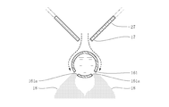
- a carrier gas heating unit 16 for heating a carrier gas supplied from a carrier gas source 14, and a carrier gas heated by the carrier gas heating unit 16.
- the first urea water is supplied to the tip of the carrier gas injection nozzle 17 so that the urea water 18 is atomized by the carrier gas injection nozzle 17 that injects the carrier gas and the carrier gas injected from the carrier gas injection nozzle 17
- a catalyst portion 23 disposed opposite to the supply nozzle 21 and the carrier gas injection nozzle 17 for decomposing the atomized urea water 18 to reform it into ammonia gas 22, and ammonia gas discharged from the outlet of the catalyst portion 23
- Urea having an ammonia gas supply nozzle 24 attached to the exhaust pipe 12 so as to supply an exhaust pipe 12 of the engine 11 It is a reformer.
- the second aspect of the present invention is an invention based on the first aspect, and further as shown in FIG. 1, a carrier gas heating unit 16, a carrier gas injection nozzle 17, a first urea water supply nozzle 21, and a catalyst unit. 23 is characterized in that the reformer housing 26 is accommodated in the reformer housing 26, and the reformer housing 26 is connected to the proximal end of the ammonia gas supply nozzle 24.
- a third aspect of the present invention is the invention based on the first or second aspect, and further as shown in FIG. 1, a coil holding portion 16a in which the carrier gas heating portion 16 is formed in a cylindrical shape,
- the carrier gas is generated by spirally winding the heating coil 16b embedded along the outer peripheral surface of the coil holding portion 16a and not exposed to the outer peripheral surface of the coil holding portion 16a, and the outer peripheral surface of the coil holding portion 16a. It is characterized by comprising a carrier gas flow path coil 16c which forms a carrier gas flow path 16d which flows spirally along the outer peripheral surface of the coil holding portion 16a.
- the fourth aspect of the present invention is an invention based on the first or second aspect, and is further provided on the outlet side of the catalyst portion 23 so as to face the outlet surface of the catalyst portion 23, as shown in FIG.
- a plurality of through holes 31a, 32a are formed, and it is characterized by further including dispersion plates 31, 32 for receiving the urea water 18 discharged from the catalyst unit 23.
- the fifth aspect of the present invention is an invention based on the first or second aspect, further as shown in FIG. 1, a catalyst heating means 41 which can be inserted directly into the catalyst portion 23 and can directly heat the catalyst portion 23, And 42.
- a selective reduction catalyst 51 provided in the exhaust pipe 12 of the engine 11 and capable of reducing NOx in exhaust gas to N 2 , and a selective reduction catalyst
- the ammonia gas supply nozzle 24 facing the exhaust pipe 12 on the exhaust gas upstream side of 51 has the ammonia gas supply nozzle 24 to supply the ammonia gas 22 functioning as a reducing agent in the selective reduction catalyst 51 to the exhaust pipe 12
- the urea water reformer 13 according to the fifth aspect and the second exhaust gas upstream side of the selective reduction catalyst 51 and the exhaust pipe 12 on the exhaust gas upstream side or the exhaust gas downstream side of the first urea water supply nozzle 21 It relates to the urea water supply means 53 having the urea water supply nozzle 52 and supplying the urea water 18 to the exhaust pipe 12 with the selective reduction catalyst 51 from the second urea water supply nozzle 52, and the selective reduction catalyst 51 Exhaust gas purification using a urea water reformer provided with a temperature sensor 54 for
- NOx in exhaust gas can be reduced to N 2 provided in exhaust pipe 12 of engine 11.
- Selective reduction type catalyst 51 a urea water reformer 214 which heats the urea water 18 by the heater 214b and reforms it into ammonia water, and urea water supply means 216 which supplies the urea water 18 to the urea water reformer 214 And either the ammonia water reformed by the urea water reformer 214 or the urea water passed as it is without being reformed by the urea water reformer 214, facing the exhaust pipe 12 on the exhaust gas upstream side of the selective reduction catalyst 51
- the injection nozzle 217 capable of injecting one or both, a catalyst temperature sensor 233 for detecting the exhaust gas temperature related to the selective reduction catalyst 51, and a pressure sensor for detecting the inlet pressure of the urea water reformer 214 And 34, characterized in that a controller
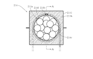
- the eighth aspect of the present invention is the invention based on the seventh aspect, and further as shown in FIG. 8, the urea water reformer 214 comprises a cylindrical reforming case 214a, and the reforming case 214a. And a plurality of inorganic porous bodies 214c that are filled in the reforming case 214a and transmit the heat of the heater 214b to the inside of the reforming case 214a. I assume.
- the ninth aspect of the present invention is the invention based on the eighth aspect, and further as shown in FIG. 11, a partition plate 264f is formed in the reforming case 264a with a predetermined interval in the longitudinal direction of the case.
- a plurality of spaces are provided and divided by the partition plate 264f into a plurality of spaces in which the inside of the reforming case 264a communicates with each other, the plurality of spaces are filled with a plurality of inorganic porous bodies 264c, and a plurality of urea waters flowing into the reforming case 264a It is characterized in that it is configured to pass through the space of (1) in a meandering manner to be reformed into ammonia water.
- the tenth aspect of the present invention is the invention based on the eighth or ninth aspect, and further, as shown in FIG. 8, the inorganic porous body 214 c carries a catalyst that promotes the hydrolysis of the aqueous urea 18. It is characterized by
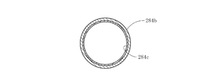
- the urea water reformer 284 comprises a rod-shaped heater 284a and an outer peripheral surface of the heater 284a. And a reducing agent flow pipe 284b for circulating urea water and transferring the heat of the heater 284a to the inner surface, and an adsorbent layer 284c coated on the inner circumferential surface of the reducing agent flow pipe 284b for adsorbing urea water. And.
- a twelfth aspect of the present invention is the invention based on the eleventh aspect, and further, as shown in FIG. 16, the adsorbent layer 284c is characterized in that a catalyst that promotes the hydrolysis of aqueous urea is supported. Do.
- the carrier gas heating means heats the carrier gas supplied from the carrier gas source, and the heated carrier gas is jetted from the carrier gas jet nozzle.
- the urea water supplied from the urea water supply nozzle is atomized by the carrier gas injected from the carrier gas injection nozzle, and the atomized urea water is further decomposed in the catalyst portion and reformed into ammonia gas. Can be efficiently reformed to ammonia gas in the catalyst section.
- the urea water is sufficiently atomized as compared with the conventional exhaust gas denitration apparatus in which the urea water is not sufficiently atomized because the urea water is injected from the urea water ejection part at a relatively low temperature.
- the carrier gas heating unit, the carrier gas injection nozzle, the first urea aqueous solution feed nozzle and the catalyst unit are accommodated in a reformer housing, and the reformer housing is ammonia Being connected to the proximal end of the gas supply nozzle, the reformer housing can be mounted relatively easily on the exhaust pipe with the ammonia gas supply nozzle.
- the coil holding portion having high thermal conductivity is formed in a cylindrical shape, and is not exposed along the outer peripheral surface of the coil holding portion and on the outer peripheral surface of the coil holding portion
- the electric heating coil is embedded in the coil, and the carrier gas flow path coil having a high thermal conductivity is spirally wound on the outer peripheral surface of the coil holding portion, whereby the carrier gas flows spirally along the outer peripheral surface of the coil holding portion Since the carrier gas flow channel is formed, the carrier gas flow channel in the carrier gas heating unit can be sufficiently secured. As a result, the carrier gas can be sufficiently heated in the carrier gas heating unit.
- urea aqueous solution flows to the duct, urea aqueous solution adheres to the inner wall of the duct, and the urea aqueous solution does not flow smoothly in the duct, compared with the conventional reducing agent-containing gas flow generating device. Since only the carrier gas flows without the urea water flowing in the gas flow path, it is possible to prevent the urea water from adhering to the inner wall of the carrier gas flow path. As a result, the carrier gas flows smoothly in the carrier gas channel.
- a diffusion plate having a high thermal conductivity which has a plurality of through holes formed therein and receives urea aqueous solution discharged from the catalyst unit, is disposed on the outlet side of the catalyst unit. Since it is provided facing the outlet surface, when the atomized urea water passes through the catalyst portion without being reformed into ammonia gas in the catalyst portion, it collides with the dispersion plate. Since the droplets of urea water which collided with the dispersion plate are deprived of heat from the dispersion plate and decomposed into ammonia gas, the amount of ammonia gas generated can be increased, and the flow of urea water into the exhaust pipe can be prevented.
- the catalyst heating means directly heats the catalyst portion, the temperature of the catalyst portion is maintained at a temperature at which the atomized urea water can be reformed into ammonia gas. As a result, the reforming efficiency of the atomized urea water into ammonia gas in the catalyst portion can be improved.
- the controller keeps the urea water supply means stopped and drives the urea water reformer.
- the urea water reformer decomposes the urea water and reforms it into ammonia gas
- the ammonia gas is supplied from the ammonia gas supply nozzle to the exhaust pipe.
- the ammonia gas flows into the selective reduction catalyst together with the exhaust gas
- the ammonia gas functions as a reducing agent for reducing NOx in the exhaust gas, and the NOx in the exhaust gas is promptly reduced to N 2 .
- NOx can be reduced efficiently.
- the controller stops the urea water reformer and drives the urea water supply means. Thereby, urea water is injected to the exhaust pipe from the second urea water supply nozzle of the urea water supply means. At this time, since the exhaust gas temperature is relatively high, urea water is quickly decomposed into ammonia gas in the exhaust pipe. Then, when the ammonia gas flows into the selective reduction catalyst together with the exhaust gas, the ammonia gas functions as a reducing agent for reducing NOx in the exhaust gas, and the NOx in the exhaust gas is promptly reduced to N 2 . As a result, even if the exhaust gas temperature rises, NOx can be reduced efficiently.
- the aqueous ammonia water or urea aqueous solution is reformed into ammonia water without evaporating urea water by the urea water reformer, and the volume hardly changes even if the pressure changes. Since either one or both of the two are injected from the injection nozzle into the exhaust pipe, the supply amount of ammonia water or urea water to the exhaust pipe can be easily controlled. In addition, ammonia water injected from the injection nozzle into the exhaust pipe is quickly vaporized to ammonia gas even if the exhaust gas temperature is relatively low, and this ammonia gas is used to selectively NOx in exhaust gas on the selective reduction catalyst.
- the urea water Since it functions as a reducing agent to reduce to 2 , NOx in the exhaust gas can be efficiently reduced even when the exhaust gas temperature is relatively low.
- the urea water When the exhaust gas temperature is relatively high, the urea water is allowed to pass as it is without being reformed by the urea water reformer and injected from the injection nozzle to the exhaust pipe. Since the injected urea water is reformed into ammonia gas by the relatively high temperature exhaust gas, the ammonia gas functions as a reducing agent for reducing NOx in the exhaust gas to N 2 on the selective reduction catalyst.
- urea water is reformed into ammonia water without being evaporated by the urea water reformer, it is possible to prevent the water from being evaporated and the urea from being crystallized. As a result, deposition of crystallized urea in the urea water reformer can be prevented. Furthermore, since the evaporation chamber and the hydrolysis catalytic converter are separately provided to generate the reducing agent mixture containing ammonia from the aqueous urea solution, the number of parts is increased, and the evaporation chamber and the hydrolysis catalytic converter are installed.
- the urea aqueous solution is reformed into liquid ammonia water in a single urea water reformer, as compared with the conventional mixture supply device which must secure a large space.
- the urea water reformer can be miniaturized without increasing the number of parts of the reformer. As a result, the urea water reformer can be installed in a relatively narrow space.
- the inorganic porous body filled in the reforming case has a function as a heat medium for transferring the heat of the heater to the inside of the reforming case, and soak in urea water. Since it has a function as an adsorbing agent to be adsorbed on urea, urea water can be efficiently reformed into ammonia water.
- the urea water flowing into the reforming case meanders through a plurality of spaces, the contact ratio of the urea water to the inorganic porous body becomes high, and the urea water is increased. Can be reformed into ammonia water more efficiently.
- the urea water can be more efficiently reformed into ammonia water.
- the reducing agent flow pipe transmits the heat of the heater to the inner surface of the reducing agent flow pipe, and the adsorbent layer adsorbs so as to impregnate the urea water.
- the agent flow pipe By passing through the agent flow pipe, it can be efficiently reformed into ammonia water.
- the reducing agent flow pipe is formed on the outer peripheral surface of the rod-shaped heater, as compared with the conventional exhaust gas processing apparatus in which the outer pipe and the bush need to be processed with high accuracy and the number of processing steps of these parts increases. Since only spiral winding is required, the reducing agent flow pipe can be manufactured relatively easily with relatively low accuracy without increasing the number of processing steps.
- the urea water can be more efficiently reformed into ammonia water.
- FIG. 10 is a cross-sectional view taken along line AA of FIG. 9 showing a urea water reformer of the exhaust gas purification apparatus.
- FIG. 9 is a cross-sectional view taken along the line BB of FIG.
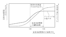
- FIG. 8 It is a figure which shows the change of the ammonia water generation rate in a urea water reformer with respect to the temperature change of a urea water reformer, and the change of the inlet pressure of a urea water reformer.
- FIG. 13 is a cross-sectional view taken along line CC in FIG. 12 showing a urea water reformer according to a seventh embodiment of the present invention.
- FIG. 12 is a cross-sectional view taken along the line DD of FIG.
- FIG. 15 is a cross-sectional view taken along the line EE of FIG. 14 showing a urea water reformer according to an eighth embodiment of the present invention.
- FIG. 14 is a cross-sectional view taken along line FF of FIG.
- FIG. 13 It is a side view of the urea water reformer which shows the state which removed the heat insulation case and the heat insulating material of a urea water reformer. It is the GG sectional view taken on the line of FIG.
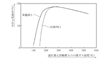
- FIG. 7 is a view showing a change in NOx reduction rate accompanying a change in exhaust gas temperature when the exhaust gas purification apparatus of Example 1 and Comparative Example 1 is used.
- the exhaust pipe 12 of the diesel engine 11 is provided with a urea water reformer 13.
- the urea water reformer 13 includes a carrier gas heating unit 16 for heating the carrier gas supplied from the carrier gas source 14, and a carrier gas injection nozzle 17 for jetting the carrier gas heated by the carrier gas heating unit 16.
- the first urea water supply nozzle 21 for supplying urea water 18 to the tip of the carrier gas injection nozzle 17 so that the urea water 18 is atomized by the carrier gas injected from the carrier gas injection nozzle 17, and the atomized urea
- the catalyst unit 23 decomposes the water 18 and reforms the ammonia 18 into ammonia gas 22.
- the ammonia gas supply nozzle 24 supplies the ammonia gas 22 discharged from the outlet of the catalyst unit 23 to the exhaust pipe 12 of the engine 11.
- the carrier gas heating unit 16, the carrier gas injection nozzle 17, the first urea water supply nozzle 21 and the catalyst unit 23 are accommodated in a cylindrical reformer housing 26 extending in the vertical direction, and the lower end of the reformer housing 26 is Is connected to the upper end of the ammonia gas supply nozzle 24. This makes it possible to mount the reformer housing 26 relatively easily on the exhaust pipe 12 together with the ammonia gas supply nozzle 26.
- the carrier gas source 14 in this embodiment is a carrier gas tank (air tank) for storing carrier gas (air) compressed by a compressor (not shown) (FIG. 2).
- the carrier gas source may be a compressor that supplies air in the atmosphere, exhaust gas of the engine, or a mixed gas thereof to the carrier gas heating unit without using a carrier gas tank (air tank).
- a stepped flange 16e is integrally provided at the upper end, and a coil holding unit 16a formed in a columnar shape extending in the vertical direction and a coil holding along the outer peripheral surface of the coil holding unit 16a. It consists of an electric heating coil 16b embedded so as not to be exposed on the outer peripheral surface of the portion 16a, and a carrier gas flow path coil 16c spirally wound on the outer peripheral surface of the coil holding portion 16a (FIG. 1).
- the coil holding portion 16a is formed of a metal having a relatively high thermal conductivity of 15 to 17 W / (m ⁇ K), such as SUS316 and Inconel (registered trademark of Special Metals Corporation).
- the heating coil 16b has a heating element such as a nichrome wire loosely inserted in a metal sheath (a metal capillary), and a powder of high purity inorganic insulator is inserted in the gap between the metal sheath and the heating element. Filled and configured.
- a heating element such as a nichrome wire loosely inserted in a metal sheath (a metal capillary)
- a powder of high purity inorganic insulator is inserted in the gap between the metal sheath and the heating element. Filled and configured.
- a columnar first holding portion slightly smaller in diameter than the coil holding portion 16a is prepared, and the outer peripheral surface of the first holding portion
- a helical recess capable of accommodating the electric heating coil 16b is formed, and the electric heating coil 16b is accommodated in the helical recess, and then the cylindrical second holding portion having the same outer diameter as the coil holding portion 16a is The method of fitting to a 1st holding part etc. are used.
- the carrier gas flow path coil 16c is formed by spirally winding a metal wire having a relatively high thermal conductivity of 15 to 17 W / (m ⁇ K), such as SUS316, SUS304, or Inconel, around the outer peripheral surface of the coil holding portion 16a. It is formed by doing.
- the carrier gas flow path coil 16c is spirally wound with a predetermined distance D (FIG. 1) between the metal wires adjacent to each other, whereby the carrier gas is drawn along the outer peripheral surface of the coil holding portion 16a.
- a carrier gas flow path 16 d which flows spirally is formed. That is, the space formed by opening the predetermined distance D is configured to be the carrier gas flow path 16 d through which the carrier gas flows.
- the carrier gas heating unit 16 is accommodated in the upper portion of a heating unit case 27 which is formed in a cylindrical shape at the upper portion and a funnel shape which is tapered toward the lower portion, and the heating portion case 27 is a reformer housing 26. Inserted at the top of the Further, when the carrier gas heating unit 16 is accommodated in the heating unit case 27, the range of 0.4 to 0.5 mm is provided between the outer peripheral surface of the carrier gas flow path coil 16c and the inner peripheral surface of the heating unit case 27. An internal gap t (FIG. 1) is formed.
- the gap t when the gap t is limited within the range of 0.4 to 0.5 mm, if it is less than 0.4 mm, it is generated by the electric heating coil 16b and transmitted to the carrier gas flow path coil 16c through the coil holding portion 16a. Heat is transmitted to the heating unit case 27 and dissipated, and when it exceeds 0.5 mm, most of the carrier gas does not flow in the spiral carrier gas flow path 16d but flows through the gap t, and the carrier gas Can not be heated sufficiently by the carrier gas heating unit 16.
- the carrier gas injection nozzle 17 is formed at the lower end of the heating unit case 27 so that the carrier gas heated by the carrier gas heating unit 16 is injected downward from the tip (lower end) of the carrier gas injection nozzle 17. Configured Reference numeral 28 in FIGS.
- FIG. 1 and 2 denotes a carrier gas supply pipe connected to the upper part of the reformer housing 26 and the heating unit case 27.
- the base end of the carrier gas supply pipe 28 is connected to the carrier gas tank 14 (FIG. 2), and the tip is connected to the carrier gas flow path 16 d (FIG. 1).
- the first urea water supply nozzle 21 is inserted horizontally extending from the outer peripheral surface of the substantially central portion of the reformer housing 26 in the vertical direction. Specifically, the first urea aqueous solution supply nozzle 21 is horizontally inserted into the reformer housing 26 so that the tip thereof is positioned slightly lower than the tip of the carrier gas injection nozzle 17 at the lower end of the heating unit case 27. Ru. Further, the tip of the first urea water supply nozzle 21 is closed, and a urea water feed hole 21a penetrating in the vertical direction is provided at a position facing the tip of the carrier gas injection nozzle 17 in the tip of the first urea water supply nozzle 21. It is formed.
- the urea water 18 supplied to the urea water supply hole 21 a of the first urea water supply nozzle 21 is blown away by the carrier gas injected from the carrier gas injection nozzle 17. It is atomized and its temperature rises.
- the catalyst unit 23 faces the carrier gas injection nozzle 17 and is provided at a relatively large distance from the first urea aqueous solution supply nozzle 21 at the lower side, and a first catalyst It consists of the 2nd catalyst part 23b provided below with a comparatively small space
- the first and second catalyst portions 23a and 23b are configured identically. Specifically, the first and second catalyst portions 23a and 23b are monolith catalysts, and are configured by coating a honeycomb carrier made of cordierite with titania, zirconia or zeolite. The first and second catalyst portions 23a and 23b made of titania are configured by coating a slurry containing titania on a honeycomb carrier.
- the first and second catalyst portions 23a and 23b made of zirconia are formed by coating a slurry containing zirconia on a honeycomb carrier. Furthermore, the first and second catalyst portions 23a and 23b made of zeolite are configured by coating a slurry containing zeolite powder on a honeycomb carrier.
- the cordierite honeycomb carrier may be a metal carrier formed of stainless steel.
- the atomized urea water 18 gradually spreads downward as it goes downward, over the entire inlet surface (upper surface) of the first catalyst portion 23a. It is comprised so that it may disperse
- a 2 dispersion plate 32 is provided on the outlet side (lower side) of the second catalyst portion 23b and on the inlet side (upper side) of the ammonia gas supply nozzle 24 so as to face the outlet surface (lower surface) of the second catalyst portion 23b.
- a 2 dispersion plate 32 is provided.
- a plurality of through holes 31a, 32a are respectively formed in the first and second dispersion plates 31, 32, and are configured to receive the urea water 18 discharged from the first and second catalyst portions 23a, 23b, respectively.
- the first and second dispersion plates 31 and 32 are formed of SUS316, SUS304, Inconel, or the like, which has a relatively high thermal conductivity of 15 to 17 W / (m ⁇ K).
- a first glow plug 41 capable of directly heating the first catalyst portion 23a is inserted into the first catalyst portion 23a, and a second glow capable of directly heating the second catalyst portion 23b is included in the second catalyst portion 23b.
- the plug 42 is inserted.
- the first glow plug 41 extends horizontally from the vertical center of the first catalyst portion 23a and is inserted, and the second glow plug 42 extends horizontally from the vertical center of the second catalyst portion 23b and inserted.
- the first and second glow plugs 41, 42 are substantially identical to the glow plugs attached to the cylinder head of the diesel engine and preheating the combustion chamber of the engine, and have a structure in which the heating wire is incorporated in the metal tube. There is.
- the ammonia gas supply nozzle 24 is attached to the exhaust pipe 12 of the engine 11.
- the ammonia gas supply nozzle 24 comprises a cylindrical nozzle body 24a and a flange 24b integrally formed with the nozzle body 24a at the upper end of the nozzle body 24a.
- the lower surface of the nozzle body 24a is formed as an inclined surface in which the length of the nozzle body 24a is gradually shortened from the upstream side of the exhaust gas toward the downstream side of the exhaust gas.
- the flange portion 24 b is attached to the flange portion 12 a provided on the exhaust pipe 12.
- the urea water reformer 13 is incorporated into an exhaust gas purification device of the diesel engine 11, as shown in FIG.
- This exhaust gas purification apparatus includes the selective reduction catalyst 51 provided in the exhaust pipe 12 of the engine 11 and the above-described urea water reforming having an ammonia gas supply nozzle 24 facing the exhaust pipe 12 on the exhaust gas upstream side of the selective reduction catalyst 51
- a urea aqueous solution supply unit 53 having a second urea aqueous solution supply nozzle 52 facing the exhaust pipe 12 upstream of the exhaust gas from the selective reduction catalyst 51 and facing the exhaust gas downstream of the first urea aqueous solution supply nozzle 21;
- the temperature sensor 54 detects exhaust gas temperature related to the reduction type catalyst 51, and the controller 56 controls the urea water reformer 13 and the urea water supply means 53 based on the detection output of the temperature sensor 54.
- the selective reduction catalyst 51 is accommodated from the exhaust pipe 12 to the large diameter of the case 57, reducible configured NOx in the exhaust gas to N 2.
- the selective reduction catalyst 51 is a monolith catalyst and is configured by coating a honeycomb carrier made of cordierite with zeolite or zirconia. Examples of zeolite include copper zeolite, iron zeolite, zinc zeolite and silver zeolite.
- the selective reduction catalyst 51 made of copper zeolite is configured by coating a honeycomb carrier with a slurry containing zeolite powder ion-exchanged with copper.
- the selective reduction type catalyst 51 made of iron zeolite, zinc zeolite or silver zeolite is formed by coating a slurry containing zeolite powder ion-exchanged with iron, zinc or silver on a honeycomb carrier.
- the selective reduction catalyst 51 made of zirconia is formed by coating a slurry containing a zirconia-supported ⁇ -alumina powder or ⁇ -alumina powder on a honeycomb carrier.
- the urea water reformer 13 is connected to the first urea water supply pipe 61 whose tip is connected to the first urea water supply nozzle 21 and the base end of the first urea water supply pipe 61, and the urea water 18 is A first urea water tank 62 stored, a first pump 63 for pressure-feeding the urea water 18 in the first urea water tank 62 to the first urea water supply nozzle 21, and a carrier gas from the first urea water supply nozzle 21 Carrier gas for connecting the first urea water supply amount adjustment valve 64 for adjusting the supply amount of urea water 18 supplied to the tip of the injection nozzle 17 and the carrier gas flow path 16 d of the carrier gas tank 14 and the carrier gas heating unit 16 And a carrier gas flow control valve 66 provided in the supply pipe 28 (FIG.
- the first pump 63 is provided in the first urea water supply pipe 61 between the first urea water supply nozzle 21 and the first urea water tank 62, and the first urea water supply control valve 64 is for supplying the first urea water.
- the first urea water supply pipe 61 between the nozzle 21 and the first pump 63 is provided.
- the first urea water supply amount adjustment valve 64 is provided in the first urea water supply pipe 61, and the first urea water pressure adjustment valve 64a for adjusting the supply pressure of the urea water 18 to the first urea water supply nozzle 21;
- the first urea water supply nozzle 21 includes a first urea water on-off valve 64 b provided at the base end of the first urea water supply nozzle 21 and opening and closing the base end of the first urea water supply nozzle 21.
- the first urea water pressure control valve 64a is a three-way valve having first to third ports 64c to 64e, the first port 64c is connected to the discharge port of the first pump 63, and the second port 64d is the first urea water
- the third port 64 e is connected to the first urea water tank 62 by the first return pipe 65.
- the carrier gas flow rate adjustment valve 66 is configured to be able to adjust the flow rate of the carrier gas supplied from the carrier gas tank 14 to the carrier gas flow path 16 d of the carrier gas heating unit 16.
- the urea aqueous solution supply unit 53 supplies the second urea aqueous solution whose tip is connected to the second urea aqueous solution supply nozzle 52 facing the exhaust pipe 12 on the exhaust gas upstream side of the selective reduction catalyst 51 and the second urea aqueous solution supply nozzle 52
- a second urea water tank 72 connected to the pipe 71 and the proximal end of the second urea water supply pipe 71 and storing the urea water 18, and the urea water 18 in the second urea water tank 72 as the second urea water It has a second pump 73 for pressure feeding to the supply nozzle 52, and a second urea water supply amount adjustment valve 74 for adjusting the supply amount of urea water 18 supplied from the second urea water supply nozzle 52 to the exhaust pipe 12 (see FIG.
- the urea water 18 is decomposed into ammonia gas by the relatively high temperature exhaust gas, and the ammonia gas functions as a reducing agent in the selective reduction catalyst 51.
- the second pump 73 is provided in the second urea water supply pipe 71 between the second urea water supply nozzle 52 and the second urea water tank 72, and the second urea water supply amount adjustment valve 74 is the second urea water.
- the second urea aqueous solution supply pipe 71 between the supply nozzle 52 and the second pump 73 is provided.
- the second urea water supply amount adjustment valve 74 is provided in the second urea water supply pipe 71, and the second urea water pressure adjustment valve 74a for adjusting the supply pressure of the urea water 18 to the second urea water supply nozzle 52;
- the second urea water supply nozzle 52 includes a second urea water on-off valve 74 b provided at the base end of the second urea water supply nozzle 52 for opening and closing the base end of the second urea water supply nozzle 52.
- the second urea water pressure control valve 74a is a three-way valve having first to third ports 74c to 74e, the first port 74c is connected to the discharge port of the second pump 73, and the second port 74d is a second urea water
- the third port 74 e is connected to the second urea water tank 72 by the second return pipe 75.
- the urea water 18 pressure-fed by the second pump 73 flows from the first port 74c into the second urea water pressure control valve 74a, and the second urea water pressure control valve 74a After the pressure is adjusted to a predetermined pressure, the pressure is fed from the second port 74 d to the second urea water on-off valve 74 b.
- the urea water 18 pressure-fed by the second pump 73 flows from the first port 74c into the second urea water pressure control valve 74a, and then from the third port 74e It is returned to the second urea aqueous solution tank 72 through the second return pipe 75.
- an intake pipe 82 is connected to an intake port of the diesel engine 11 via an intake manifold 81, and an exhaust pipe 12 is connected to an exhaust port via an exhaust manifold 83 (FIG. 2).
- the intake pipe 82 is provided with a compressor housing 84 a of the turbocharger 84 and an intercooler 86 for cooling the intake air compressed by the turbocharger 84.
- the exhaust pipe 12 has a turbine of the turbocharger 84.
- a housing 84b is provided.
- a compressor rotor (not shown) is rotatably housed in the compressor housing 84a, and a turbine rotor (not shown) is rotatably housed in the turbine housing 84b.
- the compressor rotor and the turbine rotor are connected by a shaft (not shown), and energy of exhaust gas discharged from the engine 11 rotates the compressor rotor via the turbine rotor and the shaft, and the compressor rotor rotates.
- the intake air in the intake pipe 82 is compressed.
- the temperature sensor 54 is selected from a first temperature sensor 54a inserted in the case 57 on the exhaust gas inlet side of the selective reduction catalyst 51 and detecting the temperature of the exhaust gas just before flowing into the selective reduction catalyst 51;
- the second temperature sensor 54b is inserted into a case 57 on the exhaust gas outlet side of the reduction catalyst 51 and detects the temperature of the exhaust gas immediately after flowing out from the selective reduction catalyst 51.
- the rotation speed of the engine 11 is detected by a rotation sensor 87, and the load of the engine 11 is detected by a load sensor 88.
- the detection outputs of the first temperature sensor 54a, the second temperature sensor 54b, the rotation sensor 87, and the load sensor 88 are connected to the control input of the controller 56, and the control output of the controller 56 is the heating coil 16b, the first glow plug 41, the first 2 glow plug 42, first pump 63, first urea water pressure control valve 64a, first urea water on-off valve 64b, carrier gas flow control valve 66, second pump 73, second urea water pressure control valve 74a, second 2 Urea water on-off valve 74b is connected to each.
- the controller 56 is provided with a memory 89.
- the pressure of the first urea water pressure control valve 64a and the pressure of the second urea water pressure control valve 74a according to the engine rotational speed, the engine load, and the exhaust gas temperature at the inlet / outlet of the selective reduction catalyst 51, the first urea water
- the number of times of opening and closing per unit time of the on-off valve 64b and the second urea water on-off valve 74b, the presence or absence of the operation of the first pump 63 and the second pump 73, and the opening degree of the carrier gas flow rate adjustment valve 66 are stored in advance.
- the memory 89 also stores, as a map, changes in the flow rate of NOx in the exhaust gas discharged from the engine 11 based on changes in engine rotational speed and engine load.
- the first temperature sensor is inserted into the case of the exhaust gas inlet side of the selective reduction catalyst
- the second temperature sensor is inserted into the case of the exhaust gas outlet side from the selective reduction catalyst.
- the temperature related to the catalyst can be detected, either one of the first and second temperature sensors may be used.
- the exhaust gas purification apparatus having the urea water reformer 13 configured as described above will be described.
- the exhaust gas temperature is as low as 100 to 200.degree.
- the controller 56 detects the first temperature A state in which the second pump 73, the second urea water pressure control valve 74a, and the second urea water on-off valve 74b are stopped based on the detection outputs of the sensor 54a, the second temperature sensor 54b, the rotation sensor 87, and the load sensor 88.
- the first pump 63, the first urea water pressure control valve 64a, the first urea water on-off valve 64b, and the carrier gas flow control valve 66 are driven.
- the carrier gas in the carrier gas tank 14 is supplied to the carrier gas flow path 16 d of the carrier gas heating unit 16.
- the carrier gas reaches the carrier gas injection nozzle 17 while depriving the heat generated in the electric heating coil 16b and transferred to the coil holding portion 16a and the carrier gas flow path coil 16c while flowing in the carrier gas flow path 16d. Since the carrier gas flow path 16 d is sufficiently long, the carrier gas can be sufficiently heated by the carrier gas heating unit 16.
- the first pump 63, the first urea water pressure adjusting valve 64a, and the first urea water on-off valve 64b are driven, and the electric heating coil 16b, the first glow plug 41 and the second glow plug 42 are energized.
- the urea water 18 in the first urea water tank 62 is supplied to the first urea water supply nozzle 21 through the first urea water supply pipe 61.
- the urea water 18 supplied to the first urea water supply nozzle 21 is blown off and atomized by the carrier gas injection nozzle 17 injecting the high-temperature carrier gas toward the urea water supply hole 21 a. The temperature rises.
- the atomized urea water 18 gradually spreads downward as it goes downward, and the entire inlet surface (upper surface) of the first catalyst portion 23a In the first catalyst portion 23a, most of the substantially uniformly dispersed and atomized urea water 18 is decomposed as shown in the following formula (1) and reformed into ammonia gas 22. Ru.
- the above equation (1) shows a chemical reaction equation in which the urea water 18 is decomposed into the ammonia gas 22.
- the temperature of the atomized urea water 18 immediately before flowing into the first catalyst portion 23a is 90 to 150.degree.
- the temperature of the first catalyst portion 23a is directly heated by the first glow plug 41, and the temperature of the first catalyst portion 23a is reduced to a temperature (for example, 200 to 300 ° C.) at which urea water 18 can be reformed into ammonia gas 22. Since this is maintained, the reforming efficiency of the atomized urea water 18 into the ammonia gas 22 in the first catalyst portion 23a can be improved.
- the atomized urea water 18 passes through the first catalyst portion 23 a without being reformed to the ammonia gas 22 by the first catalyst portion 23 a, it collides with the first dispersion plate 31.
- the urea water 18 colliding with the first dispersion plate 31 is deprived of heat from the first dispersion plate 31 and decomposed into the ammonia gas 22, so the amount of generation of the ammonia gas 22 can be increased.
- the atomized urea water 18 passes through the first catalyst portion 23a and the first dispersion plate 31 without being reformed to the ammonia gas 22, the atomized urea water 18 is decomposed by the second catalyst portion 23b. It is reformed to ammonia gas 22.
- the second catalyst portion 23b is directly heated by the second glow plug 41, and the temperature of the second catalyst portion 23b is maintained at a temperature at which the atomized urea water 18 can be reformed into the ammonia gas 22, atomization
- the reforming efficiency of the aqueous urea solution 18 into the ammonia gas 22 in the second catalyst portion 23b can be improved.
- the atomized urea water 18 passes through the second catalyst portion 23 b without being reformed to the ammonia gas 22 by the second catalyst portion 23 b, the atomized water collides with the second dispersion plate 32.
- the urea water 18 which has collided with the second dispersion plate 32 is deprived of heat from the second dispersion plate 32 and decomposed into the ammonia gas 22. Therefore, the generation amount of the ammonia gas 22 can be increased, and the urea water to the exhaust pipe 12 is The inflow of 18 droplets can be blocked.
- the ammonia gas 22 is supplied from the ammonia gas supply nozzle 24 to the exhaust pipe 12. Then, when the ammonia gas 22 flows into the selective reduction catalyst 51 together with the exhaust gas, the ammonia gas 22 functions as a reducing agent for reducing NOx (NO, NO 2 ) in the exhaust gas, and the following equation (2) as shown, NOx in the exhaust gas is reduced rapidly to N 2.
- the controller 56 controls the first pump 63, the first urea water pressure control valve 64a, and the first urea water based on the detection outputs of the first and second temperature sensors 54a, 54b.
- the drive of the on-off valve 64b and the carrier gas flow rate adjustment valve 66 is stopped, and the energization of the electric heating coil 16b, the first glow plug 41 and the second glow plug 42 is stopped.
- the controller 56 drives the second pump 73, the second urea water pressure adjustment valve 74a, and the second urea water on-off valve 74b.
- the urea water 18 stored in the second urea water tank 72 of the urea water supply means 53 is injected from the second urea water supply nozzle 52 to the exhaust pipe 12 through the second urea water supply pipe 71.
- the urea water 18 is quickly decomposed into the ammonia gas in the exhaust pipe 12.
- the ammonia gas flows into the selective reduction catalyst 51 together with the exhaust gas, the ammonia gas functions as a reducing agent for reducing NOx in the exhaust gas, and the NOx in the exhaust gas is rapidly reduced to N 2 .
- NOx can be reduced efficiently.
- FIG. 3 shows a second embodiment of the present invention.
- the same reference numerals as in FIG. 1 denote the same parts.
- the heating part case 102 of the urea water reformer 101 is formed in a cylindrical shape whose lower surface is closed, and the carrier gas injection nozzle 103 is formed at the center of the lower surface of the heating part case 102.
- a guide member 104 is provided which guides the flow of the high-temperature carrier gas injected from the carrier gas injection nozzle 103 so that the flow of the high-temperature carrier gas becomes conical.
- the configuration is the same as that of the first embodiment.
- the flow of the high-temperature carrier gas injected from the carrier gas injection nozzle 103 follows the downward flow as shown by the dashed arrow in FIG. Because it becomes a cone that spreads gradually, the urea water 18 that reaches the first urea water supply nozzle 21 is dispersed substantially uniformly over the entire inlet surface (upper surface) of the first catalyst portion 23a further than in the first embodiment.
- the decomposition efficiency of the substantially uniformly dispersed and atomized urea water 18 into ammonia gas in the first catalyst portion 23a is further improved as compared with the first embodiment.
- the operations other than the above are substantially the same as the operations of the first embodiment, and thus the repetitive description will be omitted.
- FIG. 4 shows a third embodiment of the present invention.
- the same reference numerals as in FIG. 1 denote the same parts.
- the ammonia gas supply nozzle 122 attached to the exhaust pipe 12 has a large-diameter cylindrical large-diameter cylindrical portion 122a inserted into the exhaust pipe 12 and a large-diameter cylindrical lower end of the large-diameter cylindrical portion 122a.
- the lower surface of the small diameter cylindrical portion 122c is formed as an inclined surface in which the length of the small diameter cylindrical portion 122c is gradually shortened from the exhaust gas upstream side toward the exhaust gas downstream side.
- the flange portion 122 d is attached to the flange portion 12 a provided on the exhaust pipe 12. Except for the above, the configuration is the same as that of the first embodiment.
- FIG. 5 shows a fourth embodiment of the present invention.
- the same reference numerals as in FIG. 1 denote the same parts.
- two urea water supply holes 141a and 141a in a direction forming an arbitrary angle with the vertical direction at a position facing the front end of the carrier gas injection nozzle 17 in the front end portion of the first urea water supply nozzle 141. Is formed. Specifically, in the cross section of the first urea water supply nozzle 141 facing the tip of the carrier gas injection nozzle 17 at the tip of the first urea water supply nozzle 141, it penetrates through the hole center of the nozzle 141. Two urea water supply holes 141a and 141a are formed respectively.
- the high temperature carrier gas injected from the carrier gas injection nozzle 17 is the first urea water supply nozzle.
- the urea water 18 is sucked out and atomized from the two urea water supply holes 141a and 141a.
- the amount of urea water 18 sucked out from the two urea water supply holes 141a and 141a is larger than the amount of urea water blown off from the lower urea water supply holes of the first embodiment.
- the operation other than the above is substantially the same as the operation of the urea reformer according to the first embodiment, and thus the description thereof will not be repeated.
- FIG. 6 shows a fifth embodiment of the present invention.
- the same reference numerals as in FIG. 1 denote the same parts.
- two urea water supply holes 161a and 161a in a direction forming an arbitrary angle with the vertical direction at a position facing the front end of the carrier gas injection nozzle 17 in the front end portion of the first urea water supply nozzle 161 Are formed respectively.
- a vertical line passing the hole center of the nozzle 161 In the cross section of the first urea water supply nozzle 161 facing the tip of the carrier gas injection nozzle 17 at the tip of the first urea water supply nozzle 161, a vertical line passing the hole center of the nozzle 161
- two urea water supply holes 161a and 161a are respectively formed extending in the direction of about 45 degrees obliquely downward from the hole center of the nozzle 161.
- the high temperature carrier gas injected from the carrier gas injection nozzle 17 of the urea water 18 supplied to the first urea water supply nozzle 161 is the first urea water supply nozzle
- the urea water 18 is sucked and atomized from the two urea water supply holes 161a and 161a.
- the amount of urea water 18 sucked out from the two urea water supply holes 161a and 161a is larger than the amount of urea water blown off from the lower urea water supply holes of the first embodiment.
- the operation other than the above is substantially the same as the operation of the urea reformer according to the first embodiment, and thus the description thereof will not be repeated.
- the urea water reformer 214 for reforming the urea water 18 into ammonia water comprises a cylindrical reforming case 214a and the outer periphery of the reforming case 214a.
- the reforming case 214a has a cylindrical case body 214d open at one end and closed at the other end, and a flange removably attached to the open end of the case body 214d to openably close the open end of the case body 214d. It consists of 214e.
- a supply short pipe 214f for supplying urea water 18 into the reforming case 214a is connected to the center of the flange 214e, and ammonia water or urea water from the inside of the reforming case 214a is formed at the center of the closed end of the case body 214d.
- a discharge short pipe 214g for discharging the air is connected.
- the reforming case 214a is formed of a metal having a relatively high thermal conductivity of 15 to 17 W / (m ⁇ K), such as SUS316, SUS304, Inconel (registered trademark of Huntington Alloys Canada Ltd.).
- a heating element such as a nichrome wire is loosely inserted in a metal sheath (metal ultrafine tube), and the gap between the metal sheath and the heating element is filled with a high purity inorganic insulating powder. It is preferable to use a so-called sheathed heater.
- the inorganic porous body 214c it is preferable to use porous zeolite particles with a particle diameter of 0.2 to 10 mm, particles of molecular sieve (trade name of synthetic zeolite developed by Union Carbide), etc.
- the inorganic porous body 214 c has a function as a heat medium for transferring the heat of the heater 214 b to the inside of the reforming case 214 a and a function as an adsorbent for adsorbing so as to infiltrate the urea water 18.
- the inorganic porous body 214c can support a catalyst such as titania or zirconia.
- the hydrolysis of the urea water 18 can be promoted.
- the form of the inorganic porous body 214c is spherical in this embodiment, it may be an elliptical body, a cylindrical shape, a disk shape or the like.
- the urea water reformer 214 is covered by a heat insulating case 214i filled with a heat insulating material 214h. This can suppress the dissipation of the heat generated by the heater 214b.
- reference numerals 214j and 214j in FIG. 8 denote a mesh which prevents the inorganic porous body 214c from rolling out from inside the reforming case 214a into the supply short pipe 214f and the discharge short pipe 214g.
- urea water 18 is supplied to the urea water reformer 214 with the heater 214 b turned on, all the urea water 18 is reformed into ammonia water by the urea water reformer 214, and this ammonia water is injected into the injection nozzle 217. Or part of the aqueous urea solution 18 is reformed into aqueous ammonia by the aqueous urea solution reformer 214, and the remaining aqueous urea solution 18 is passed through the aqueous urea water reformer 214 without being reformed. A mixture of aqueous ammonia and aqueous urea is supplied to the injection nozzle 217.
- the urea water 18 is supplied to the urea water reformer 214 with the heater 214b turned off, the urea water 18 is not reformed at all by the urea water reformer 214, and the urea water 18 remains unchanged. It passes 214 and is supplied to the injection nozzle 217.
- the urea aqueous solution supply unit 216 connects the urea aqueous solution tank 216 a storing urea aqueous solution 18 and the urea aqueous solution tank 216 a to the supply short pipe 214 f of the urea aqueous solution reformer 214.
- a supply pipe 216 b and a pump 216 c provided in the first supply pipe 216 b and pressure-feeding the urea water 18 in the urea water tank 216 a to the urea water reformer 214 are provided.
- the pump 216c is driven by a pump drive motor (not shown).
- the pressure of the aqueous urea solution 18 discharged from the pump 216c can be adjusted by continuously or stepwise changing the speed of the pump drive motor.
- the discharge short pipe 214g of the urea water reformer 214 is connected to the injection nozzle 217 via the second supply pipe 232, and the second supply pipe 232 is opened and closed by opening and closing the second supply pipe 232.
- a flow rate adjustment valve 231 is provided to adjust the flow rate of ammonia water or urea water injected from 217.
- the flow rate adjusting valve 231 can adjust the flow rate of ammonia water or urea water injected from the injection nozzle 217 by controlling the number of opening and closing times, opening time, and closing time per unit time.
- a catalyst temperature sensor 233 for detecting an exhaust gas temperature related to the selective reduction catalyst 51 is provided on the exhaust gas inlet side of the selective reduction catalyst 51 in the catalyst case 57.
- a pressure sensor 234 for detecting the inlet pressure of the urea water reformer 214 is provided in the supply short pipe 214 f of the urea water reformer 214.
- a first urea water temperature sensor 241 for detecting the temperature of the urea water 18 on the inlet side of the reforming case 214a is provided on the inlet side of the reforming case 214a.
- a second urea water temperature sensor 242 is provided which detects the temperature of the ammonia water or urea water at the outlet side of the reforming case 214a. Furthermore, the engine 11 is provided with a rotation sensor 87 for detecting the rotational speed of the engine 11 and a load sensor 88 for detecting the load of the engine 11. Detection outputs of the catalyst temperature sensor 233, the pressure sensor 234, the first urea water temperature sensor 241, the second urea water temperature sensor 242, the rotation sensor 87, and the load sensor 88 are connected to the control input of the controller 56, and control of the controller 56 The outputs are respectively connected to the heater 214 b, the pump drive motor and the flow control valve 231.
- the controller 56 is provided with a memory 89.
- this memory 89 the speed of the pump drive motor, the number of opening and closing per unit time of the flow rate adjusting valve 231, the opening time and the closing according to the engine rotational speed, the engine load, and the exhaust gas temperature on the inlet side The time is pre-stored. Further, the memory 89 stores, as a map, changes in the flow rate of NOx in the exhaust gas according to changes in engine rotational speed and engine load.
- the memory 89 further includes an ammonia generation rate according to the inlet pressure of the urea water reformer 214, the temperature in the urea water reformer 214, and the flow rate of ammonia water or urea water discharged from the urea water reformer 214.
- Changes are stored as a map as shown in FIG. 10, for example.
- the operation area of the urea water reformer 214 when reforming the urea water 18 into ammonia water by the urea water reformer 214 changes depending on the shape of the urea water reformer 214 and the flow rate of ammonia water etc.
- the urea It is preferable to control the temperature (average temperature of each detection output of the 1st and 2nd urea water temperature sensors 241 and 242) in water reformer 214 within the limits of 100 ° C or more and less than 120 ° C by heater 214b. Since the inlet pressure of the urea water reformer 214 at this time is relatively high, the urea water reformer 214 is manufactured to have pressure resistance. Further, the heating efficiency of the urea water 18 by the heater 214 b can be detected by the temperature difference between the detection outputs of the first and second urea water temperature sensors 241 and 242.
- Reference numeral 243 in FIG. 1 denotes an EGR pipe that connects the exhaust manifold 83 and the intake pipe 82 to the engine 11 in a bypass manner.
- the EGR pipe 243 branches from the branch pipe portion of the exhaust manifold 83 and joins the intake pipe 82 on the intake downstream side of the intercooler 86.
- reference numeral 244 in FIG. 7 denotes an EGR valve which is provided in the EGR pipe 243 and adjusts the flow rate of the exhaust gas (EGR gas) returned to the intake pipe 82 from the EGR pipe 243.
- reference numeral 246 in FIG. 7 denotes an EGR cooler that cools the exhaust gas (EGR gas) passing through the EGR pipe 243.
- the exhaust gas purification apparatus configured as described above will be described.
- the exhaust gas temperature is as low as 100 to 180.degree.
- the controller 56 detects the catalyst temperature sensor 233, the rotation sensor 87, and the load sensor Based on the detection outputs of 88, the heater 214b is turned on, and the speed of the pump drive motor is gradually increased.
- the pressure sensor 234 detects that the inlet pressure of the urea water reformer 214 has reached a predetermined pressure, the pump drive motor is operated at this speed.
- the controller 56 opens and closes the flow control valve 231 at a predetermined number of times of opening and closing per unit time, a predetermined opening time and a predetermined closing time.
- Formula (4) is a hydrolysis formula from isocyanate (HNCO) to ammonia (NH 3 ).
- Ammonia (NH 3 ) generated by this hydrolysis is easily dissolved in water, so it becomes ammonia water (more than saturated water vapor pressure), carbon dioxide (CO 2 ) is hardly dissolved in water, and some is converted to ammonia water by heating. It dissolves and most of it is dispersed in ammonia water.
- the urea water reformer 214 reforms the urea water 18 into ammonia water without evaporating it, so that it is possible to prevent the water from being evaporated and the urea from being crystallized. As a result, deposition of crystallized urea in the urea water reformer 214 can be prevented. Also, although the ammonia water reformed by the urea water reformer 214 contains gaseous carbon dioxide, most of it is a liquid, and the volume does not change much even if the pressure changes. The feed rate of ammonia water can be easily controlled to the optimum flow rate.
- the ammonia water injected from the injection nozzle 217 into the exhaust pipe 12 is quickly vaporized to be ammonia gas even if the exhaust gas temperature is relatively low, and the ammonia gas flows into the selective reduction catalyst 51 together with the exhaust gas. .
- the ammonia gas flowing into the selective reduction catalyst 51 together with the exhaust gas functions as a reducing agent for reducing NOx (NO, NO 2 ) in the exhaust gas. That is, as shown by the following formula (5), NOx in the exhaust gas is rapidly reduced to N 2 by the selective reduction catalyst 51.
- the above equation (5) shows a chemical reaction equation in which NO and NO 2 in the exhaust gas react with ammonia gas at the selective reduction catalyst 51 to reduce NO and NO 2 to N 2 .
- the controller 56 turns off the heater 214 b based on the detection output of the catalyst temperature sensor 233.
- the controller 56 operates the pump drive motor at a predetermined speed, and opens and closes the flow rate adjustment valve 231 at a predetermined number of times of opening and closing (per unit time), a predetermined opening time and a predetermined closing time.
- the urea water 18 is not reformed into ammonia water by the urea water reformer 214, passes through the urea water reformer 214 as it is, and is injected from the injection nozzle 217 to the exhaust pipe 12.
- the ammonia gas functions as a reducing agent for reducing NOx in the exhaust gas to N 2 on the selective reduction catalyst 51, and the exhaust gas NOx is efficiently reduced.
- the urea water reformer 264 is filled with a cylindrical reforming case 264a, a heater 264b spirally wound around the outer peripheral surface of the reforming case 264a, and the reforming case 264a. And a plurality of inorganic porous bodies 264c.
- the reforming case 264a is releasably attached to the case body 264d having a rectangular cylindrical shape whose both ends are open, and both case faces of the case body 264d, and a pair of square plate shapes that openably close both end faces of the case body 264d.
- the partition plate 264f divides the inside of the case main body 264d into a plurality of mutually communicating spaces, and the plurality of inorganic porous bodies 264c are filled in these spaces.
- the modification case 264a is formed of the same material as the modification case of the sixth embodiment, and the inorganic porous body 264c is formed in the same shape by the same material as the inorganic porous body of the sixth embodiment. It is formed.
- a supply short pipe 264g for supplying urea water into the reforming case 264a is connected to the lower portion of the flange 264e for closing the inlet side end face of the case body 264d, and closes the outlet side end face of the case body 264d.
- a discharge short pipe 264h for discharging ammonia water or urea water from inside the reforming case 264a is connected to an upper portion of the flange 264e.
- the urea water reformer 264 is covered by the heat insulating case 264 j filled with the heat insulating material 264 i.
- reference numerals 264k and 264k in FIG. 11 denote a mesh for preventing the inorganic porous body 264c from rolling out from inside the reforming case 264a into the supply short pipe 264g and the discharge short pipe 264h.
- the configuration other than the above is the same as that of the sixth embodiment.
- the urea water flowing into the reforming case 264a passes through the plurality of spaces while meandering, so the contact ratio of the urea water with the inorganic porous body 264c becomes high, and the urea water becomes Can be reformed into ammonia water more efficiently.
- the operations other than the above are substantially the same as the operations of the sixth embodiment, and thus the repetitive description will be omitted.
- the urea water reformer 284 includes a rod-shaped heater 284a, a reducing agent flow pipe 284b spirally wound around the outer peripheral surface of the heater 284a, and a flow path of the reducing agent flow pipe 284b. And an adsorbent layer 284c (FIG. 16) coated on the inner circumferential surface and adsorbing urea water.
- a heating element such as a nichrome wire is loosely inserted into a metal sheath (metal ultrafine tube), and the gap between the metal sheath and the heating element 284d is filled with a high purity inorganic insulating powder. It is preferable to use the so-called sheathed heater 284a spirally embedded in a cylindrical body 284g.
- the reducing agent flow pipe 284b is formed of a metal having a relatively high thermal conductivity of 15 to 17 W / (m ⁇ K), such as SUS316, SUS304, Inconel (registered trademark of Huntington Alloys Canada Limited). Thereby, the heat of the heater 284a is efficiently transmitted to the inner surface of the reducing agent flow pipe 284b.
- the adsorbent layer 284c may be formed to a thickness of 0.01 to 0.1 mm using porous zeolite or molecular sieve (trade name of synthetic zeolite developed by Union Carbite). Preferred (FIG. 16). Further, the adsorbent layer 284c has a function as a heat medium for transferring the heat of the heater 284a transferred to the reducing agent flow pipe 284b to the inner side of the reducing agent flow pipe 284b, and an adsorbent for adsorbing so as to infiltrate urea water. It has a function.
- the adsorbent layer 284c can support a catalyst such as titania or zirconia.
- the hydrolysis of urea water can be promoted. Further, the urea water reformer 284 is covered with a heat insulating case 284f filled with a heat insulating material 284e (FIGS. 13 and 14). Thus, it is possible to suppress the dissipation of the heat generated by the heater 284a.
- the pressure sensor 286 for detecting the inlet pressure of the urea water reformer 284 is provided in the reducing agent flow pipe 284b immediately before being wound around the heater 284a, and the pressure of the urea water in the reducing agent flow pipe 284b is It detects (FIGS. 13 and 15).
- the surface temperature of the heater 284a in the vicinity of the winding start portion of the reducing agent flow pipe 284b to the heater 284a is detected by the first heater temperature sensor 291, and the surface temperature of the heater 284a near the winding end portion of the reducing agent flow pipe 284b to the heater 284a. Is detected by the second heater temperature sensor 292.
- the temperature of the urea water in the reducing agent flow pipe 284 b which has started to be heated by the heater 284 a is indirectly detected by the first heater temperature sensor 291.
- the temperature of the ammonia water in the reducing agent flow pipe 284b which has been heated at 284a is indirectly detected.
- one end of the reducing agent flow pipe 284b (the feed side end portion of urea water to the urea water reformer 284) is connected to the first supply pipe 216b, and the other end of the reducing agent flow pipe 284b (urea water reformer 284 The discharge side end of the ammonia water or the urea water) is connected to the second supply pipe 232.
- the configuration other than the above is the same as that of the sixth embodiment.
- the reducing agent flow pipe 284b reduces the heat of the heater 284a while the urea water is flowing in the reducing agent flow pipe 284b spirally wound around the heater 284a. Since it is transmitted to the inner surface of the agent flow pipe 284b and adsorbed so that the adsorbent layer 284c penetrates urea water, urea water can be efficiently reformed into ammonia water in the spiral reducing agent flow pipe 284b. Further, since only the reducing agent flow pipe 284b is spirally wound around the outer peripheral surface of the rod-shaped heater 284a, the reducing agent flow pipe 284b can be relatively easily manufactured with relatively low accuracy without increasing the number of processing steps. .
- the operations other than the above are substantially the same as the operations of the sixth embodiment, and thus the repetitive description will be omitted.
- the exhaust gas purification apparatus of the present invention is applied to a diesel engine.
- the exhaust gas purification apparatus of the present invention may be applied to a gasoline engine.
- the exhaust gas purification apparatus of the present invention is applied to a turbocharged diesel engine, but the exhaust gas purification apparatus of the present invention is a naturally aspirated diesel engine or a naturally aspirated gasoline It may be applied to the engine.
- two catalyst units are provided in the urea water reformer. However, one, three or four or more catalyst units may be provided.
- the catalyst temperature sensor is provided on the exhaust gas inlet side of the selective reduction catalyst in the catalyst case, but if the temperature related to the selective reduction catalyst can be detected, the catalyst temperature sensor Of the catalyst case may be provided on the exhaust gas outlet side of the selective reduction catalyst, or a catalyst temperature sensor may be provided on both the exhaust gas inlet side and the exhaust gas outlet side of the selective reduction catalyst of the catalyst case.
- Example 1 As shown in FIG. 2, the selective reduction catalyst 51 is provided in the exhaust pipe 12 of the in-line six-cylinder turbocharged diesel engine 11 having a displacement of 8000 cc.
- the selective reduction catalyst 51 was a copper-based catalyst produced by coating a honeycomb carrier with a slurry containing zeolite powder in which copper is ion-exchanged.
- a urea water reformer 13 that decomposes the urea water 18 and reforms it into ammonia gas 22 is connected to the exhaust pipe 12 on the exhaust gas upstream side of the selective reduction catalyst 51, and ammonia gas of the urea water reformer 13 is The supply nozzle 24 was inserted into the exhaust pipe 12. As shown in FIGS.
- the urea water reformer 13 includes a carrier gas heating unit 16 that heats a carrier gas (air) supplied from a carrier gas tank (air tank) 14 and a carrier gas heating unit 16.
- a carrier gas injection nozzle 17 for injecting a heated carrier gas, and urea water 18 supplied to the tip of the carrier gas injection nozzle 17 so that the urea water 18 is atomized by the carrier gas injected from the carrier gas injection nozzle 17 First urea water supply nozzle 21, a catalyst unit 23 which decomposes the atomized urea water 18 and reforms it into ammonia gas 22, and the ammonia gas 22 discharged from the outlet of the catalyst unit 23 is discharged from the engine 11 And the ammonia gas supply nozzle 24 for supplying the pipe 12.
- the catalyst unit 23 was composed of first and second catalyst units 23a and 23b, and was a catalyst prepared by coating a slurry containing titania on a honeycomb carrier. Further, the second urea water supply nozzle 52 of the urea water supply means 53 for supplying the urea water 18 is provided in the exhaust pipe 12 on the exhaust gas upstream side of the ammonia gas supply nozzle 24.
- this exhaust gas purification apparatus is referred to as Example 1.
- Comparative Example 1 The configuration was the same as that of Example 1 except that the urea water reformer was not provided. This exhaust gas purification apparatus is referred to as Comparative Example 1.
- the urea water reformer and the exhaust gas purification apparatus using the same decompose the urea water with the urea water reformer and reform it into ammonia gas, and the ammonia gas reformed with this urea water reformer Can be used to purify NOx in the exhaust gas of the engine by using the
Landscapes
- Engineering & Computer Science (AREA)
- Chemical & Material Sciences (AREA)
- Chemical Kinetics & Catalysis (AREA)
- Health & Medical Sciences (AREA)
- Toxicology (AREA)
- Combustion & Propulsion (AREA)
- Mechanical Engineering (AREA)
- General Engineering & Computer Science (AREA)
- Exhaust Gas Treatment By Means Of Catalyst (AREA)
- Exhaust Gas After Treatment (AREA)
Abstract
Un gaz porteur qui est fourni par une source de gaz porteur est chauffé par un appareil de chauffage de gaz porteur (16), le gaz porteur chauffé par l'appareil de chauffage de gaz porteur est injecté à partir d'une buse d'injection de gaz porteur (17), et une solution d'urée (18) est fournie à la pointe de la buse d'injection de gaz porteur par une première buse d'alimentation en solution d'urée (21) de sorte que la solution d'urée est atomisée par le gaz porteur injecté à partir de la buse d'injection de gaz porteur. Un catalyseur (23) permettant de décomposer la solution d'urée atomisée et de reformer la solution en un gaz d'ammoniac est prévu de manière à faire face à la buse d'injection de gaz porteur. Une buse d'alimentation en gaz d'ammoniac (24) permettant de fournir à un tuyau d'échappement de moteur (12) le gaz d'ammoniac évacué à partir d'un orifice de sortie du catalyseur est attachée au tuyau d'échappement. La solution d'urée est atomisée de façon adéquate et, par conséquent, elle est reformée de façon efficace en un gaz d'ammoniac par le catalyseur.
Priority Applications (3)
| Application Number | Priority Date | Filing Date | Title |
|---|---|---|---|
| US14/005,096 US8875499B2 (en) | 2011-03-18 | 2012-03-14 | Urea solution reformer and exhaust gas purifier using same |
| CN201280005447.7A CN103348104B (zh) | 2011-03-18 | 2012-03-14 | 尿素水重整器及使用了尿素水重整器的废气净化装置 |
| EP12760036.9A EP2687695B1 (fr) | 2011-03-18 | 2012-03-14 | Reformeur de solution d'urée et épurateur de gaz d'échappement |
Applications Claiming Priority (4)
| Application Number | Priority Date | Filing Date | Title |
|---|---|---|---|
| JP2011061154A JP5711578B2 (ja) | 2011-03-18 | 2011-03-18 | 尿素水改質器及びこれを用いた排ガス浄化装置 |
| JP2011-061154 | 2011-03-18 | ||
| JP2011287957A JP5865074B2 (ja) | 2011-12-28 | 2011-12-28 | 排ガス浄化装置 |
| JP2011-287957 | 2011-12-28 |
Publications (1)
| Publication Number | Publication Date |
|---|---|
| WO2012128145A1 true WO2012128145A1 (fr) | 2012-09-27 |
Family
ID=46879297
Family Applications (1)
| Application Number | Title | Priority Date | Filing Date |
|---|---|---|---|
| PCT/JP2012/056543 Ceased WO2012128145A1 (fr) | 2011-03-18 | 2012-03-14 | Reformeur de solution d'urée et épurateur de gaz d'échappement utilisant celui-ci |
Country Status (4)
| Country | Link |
|---|---|
| US (1) | US8875499B2 (fr) |
| EP (1) | EP2687695B1 (fr) |
| CN (1) | CN103348104B (fr) |
| WO (1) | WO2012128145A1 (fr) |
Cited By (1)
| Publication number | Priority date | Publication date | Assignee | Title |
|---|---|---|---|---|
| CN110714819A (zh) * | 2019-10-31 | 2020-01-21 | 中自环保科技股份有限公司 | 一种船机尾气scr净化系统 |
Families Citing this family (20)
| Publication number | Priority date | Publication date | Assignee | Title |
|---|---|---|---|---|
| CN109012175A (zh) | 2013-03-22 | 2018-12-18 | 日本碍子株式会社 | 还原剂喷射装置、废气处理装置以及废气处理方法 |
| US9586831B2 (en) * | 2014-06-09 | 2017-03-07 | Wahlco, Inc. | Urea to ammonia process |
| DE112014006732B4 (de) * | 2014-06-11 | 2025-07-17 | Tenneco Automotive Operating Company Inc. | Abgasnachbehandlungssystem |
| CN104047689A (zh) * | 2014-07-15 | 2014-09-17 | 中国重汽集团济南动力有限公司 | 一种带尿素水解功能的后处理系统 |
| CN105673154B (zh) | 2014-11-21 | 2019-11-08 | 天纳克(苏州)排放系统有限公司 | 共轨、该共轨的应用、尿素喷射系统及其控制方法 |
| WO2016078538A1 (fr) | 2014-11-21 | 2016-05-26 | 天纳克(苏州)排放系统有限公司 | Ensemble rail commun, système d'injection d'urée et son application |
| FR3029966B1 (fr) * | 2014-12-11 | 2018-01-26 | Psa Automobiles Sa. | Dispositif de reduction d’oxydes d’azote nox pour une ligne d’echappement de moteur thermique |
| US11585253B2 (en) | 2015-08-07 | 2023-02-21 | Cummins Emission Solutions Inc. | Converging liquid reductant injector nozzle in selective catalytic reduction systems |
| JP6676438B2 (ja) * | 2016-03-30 | 2020-04-08 | 日本碍子株式会社 | 還元剤噴射装置、排ガス処理方法、及び排ガス処理装置 |
| US9890682B2 (en) * | 2016-04-08 | 2018-02-13 | Caterpillar Inc. | System, apparatus, and method to address unwanted DEF-based deposits in diesel exhaust system |
| JP6707013B2 (ja) * | 2016-11-08 | 2020-06-10 | 三菱日立パワーシステムズ株式会社 | ガスタービンプラント、及びその運転方法 |
| WO2018232293A1 (fr) * | 2017-06-16 | 2018-12-20 | Watlow Electric Manufacturing Company | Commande basée sur la température de distribution de réactif |
| US10746071B2 (en) | 2018-05-01 | 2020-08-18 | Caterpillar Inc. | Engine aftertreatment system |
| WO2020115966A1 (fr) * | 2018-12-06 | 2020-06-11 | 日本碍子株式会社 | Dispositif d'injection d'agent réducteur, dispositif de traitement de gaz d'échappement, et procédé de traitement de gaz d'échappement |
| DE112019006135T5 (de) * | 2018-12-10 | 2021-08-19 | Ngk Insulators, Ltd. | Reduktionsmittel-Einspritzvorrichtung, Abgasverarbeitungsvorrichtung und Abgasverarbeitungsverfahren |
| FR3096737B1 (fr) * | 2019-05-29 | 2022-08-26 | Faurecia Systemes Dechappement | Dispositif d’injection d’un agent réducteur |
| JP7345405B2 (ja) * | 2019-05-30 | 2023-09-15 | 日本碍子株式会社 | 排ガス浄化装置用混合器、排ガス浄化装置及び排ガス浄化方法 |
| GB2594093A (en) * | 2020-04-17 | 2021-10-20 | Delphi Tech Ip Ltd | An exhaust gas treatment system |
| CN116322989B (zh) * | 2020-11-09 | 2025-05-06 | 日本碍子株式会社 | 还原剂生成装置的控制方法、废气净化处理方法、还原剂生成系统及废气净化处理系统 |
| WO2025213020A1 (fr) * | 2024-04-04 | 2025-10-09 | Stansell John | Systèmes sous pression et procédés de fourniture d'un catalyseur nébulisé |
Citations (10)
| Publication number | Priority date | Publication date | Assignee | Title |
|---|---|---|---|---|
| JP2002514495A (ja) * | 1998-05-11 | 2002-05-21 | シーメンス アクチエンゲゼルシヤフト | 酸素含有ガス状媒質中の窒素酸化物の選択接触還元方法及び装置 |
| JP2004000867A (ja) | 2002-03-29 | 2004-01-08 | Babcock Hitachi Kk | 排ガス脱硝装置およびこれに用いる尿素気化器 |
| JP2005344597A (ja) * | 2004-06-02 | 2005-12-15 | Hitachi Ltd | エンジン用排気ガス処理装置 |
| JP2008075527A (ja) * | 2006-09-21 | 2008-04-03 | Hitachi Ltd | 排気処理装置用の尿素水注入装置 |
| WO2009109423A1 (fr) * | 2008-02-29 | 2009-09-11 | Emitec Gesellschaft Für Emissionstechnologie Mbh | Unité d'évaporation pour la production d'ammoniac gazeux |
| JP2009537723A (ja) | 2006-05-16 | 2009-10-29 | エミテック ゲゼルシヤフト フユア エミツシオンス テクノロギー ミツト ベシユレンクテル ハフツング | 混合気の供給方法および供給装置 |
| JP2009537725A (ja) | 2006-05-16 | 2009-10-29 | エミテック ゲゼルシヤフト フユア エミツシオンス テクノロギー ミツト ベシユレンクテル ハフツング | 内燃機関の排気ガスの処理装置 |
| JP2009264148A (ja) * | 2008-04-23 | 2009-11-12 | Hino Motors Ltd | 排気浄化装置 |
| JP2009293513A (ja) * | 2008-06-05 | 2009-12-17 | Nippon Soken Inc | 内燃機関の排気浄化装置 |
| JP2010506078A (ja) | 2006-10-02 | 2010-02-25 | エミテック ゲゼルシヤフト フユア エミツシオンス テクノロギー ミツト ベシユレンクテル ハフツング | 還元剤を含む気体流を生成するための方法および装置 |
Family Cites Families (13)
| Publication number | Priority date | Publication date | Assignee | Title |
|---|---|---|---|---|
| JP2001303934A (ja) * | 1998-06-23 | 2001-10-31 | Toyota Motor Corp | 内燃機関の排気浄化装置 |
| EP1594594B1 (fr) * | 2003-02-12 | 2012-05-23 | Delphi Technologies, Inc. | Systeme de reduction des oxydes d'azote |
| JP2007501357A (ja) * | 2003-05-26 | 2007-01-25 | ハーヨットエス ファールツォイクテクニック ゲーエムベーハー ウント コー カーゲー | 第1の相から第2の相に転移された還元剤を導く供給管から、第1の相に復帰した還元剤を除去する装置 |
| JP4262522B2 (ja) * | 2003-05-28 | 2009-05-13 | 株式会社日立ハイテクノロジーズ | エンジン用排気ガス処理装置および排気ガス処理方法 |
| US7240484B2 (en) * | 2003-12-29 | 2007-07-10 | Delphi Technologies, Inc. | Exhaust treatment systems and methods for using the same |
| JP2007032472A (ja) * | 2005-07-28 | 2007-02-08 | Hitachi Ltd | 尿素水を用いた排気処理装置 |
| DE102006023146A1 (de) * | 2006-05-16 | 2007-11-22 | Emitec Gesellschaft Für Emissionstechnologie Mbh | Verfahren und Vorrichtung zum Bereitstellen eines gasförmigen Stoffgemisches |
| JP4285528B2 (ja) | 2006-11-06 | 2009-06-24 | トヨタ自動車株式会社 | 内燃機関の排気再循環システム |
| US8591848B2 (en) * | 2007-11-09 | 2013-11-26 | Fuel Tech, Inc. | Selective catalytic NOx reduction process and control system |
| JP4325725B2 (ja) * | 2008-02-14 | 2009-09-02 | トヨタ自動車株式会社 | 内燃機関の尿素水供給装置 |
| EP2335812B1 (fr) * | 2008-02-25 | 2016-12-07 | JGC Catalysts and Chemicals Ltd. | Appareil pour traiter un gaz d'échappement |
| JP2011516770A (ja) | 2008-02-29 | 2011-05-26 | エミテック ゲゼルシヤフト フユア エミツシオンス テクノロギー ミツト ベシユレンクテル ハフツング | 少なくとも1つの還元剤前駆体および/または還元剤を含むガスを生成するための蒸発装置 |
| EP2626529B1 (fr) * | 2011-11-09 | 2015-10-21 | Toyota Jidosha Kabushiki Kaisha | Dispositif d'épuration de l'échappement pour moteur à combustion interne |
-
2012
- 2012-03-14 WO PCT/JP2012/056543 patent/WO2012128145A1/fr not_active Ceased
- 2012-03-14 CN CN201280005447.7A patent/CN103348104B/zh not_active Expired - Fee Related
- 2012-03-14 EP EP12760036.9A patent/EP2687695B1/fr not_active Not-in-force
- 2012-03-14 US US14/005,096 patent/US8875499B2/en not_active Expired - Fee Related
Patent Citations (10)
| Publication number | Priority date | Publication date | Assignee | Title |
|---|---|---|---|---|
| JP2002514495A (ja) * | 1998-05-11 | 2002-05-21 | シーメンス アクチエンゲゼルシヤフト | 酸素含有ガス状媒質中の窒素酸化物の選択接触還元方法及び装置 |
| JP2004000867A (ja) | 2002-03-29 | 2004-01-08 | Babcock Hitachi Kk | 排ガス脱硝装置およびこれに用いる尿素気化器 |
| JP2005344597A (ja) * | 2004-06-02 | 2005-12-15 | Hitachi Ltd | エンジン用排気ガス処理装置 |
| JP2009537723A (ja) | 2006-05-16 | 2009-10-29 | エミテック ゲゼルシヤフト フユア エミツシオンス テクノロギー ミツト ベシユレンクテル ハフツング | 混合気の供給方法および供給装置 |
| JP2009537725A (ja) | 2006-05-16 | 2009-10-29 | エミテック ゲゼルシヤフト フユア エミツシオンス テクノロギー ミツト ベシユレンクテル ハフツング | 内燃機関の排気ガスの処理装置 |
| JP2008075527A (ja) * | 2006-09-21 | 2008-04-03 | Hitachi Ltd | 排気処理装置用の尿素水注入装置 |
| JP2010506078A (ja) | 2006-10-02 | 2010-02-25 | エミテック ゲゼルシヤフト フユア エミツシオンス テクノロギー ミツト ベシユレンクテル ハフツング | 還元剤を含む気体流を生成するための方法および装置 |
| WO2009109423A1 (fr) * | 2008-02-29 | 2009-09-11 | Emitec Gesellschaft Für Emissionstechnologie Mbh | Unité d'évaporation pour la production d'ammoniac gazeux |
| JP2009264148A (ja) * | 2008-04-23 | 2009-11-12 | Hino Motors Ltd | 排気浄化装置 |
| JP2009293513A (ja) * | 2008-06-05 | 2009-12-17 | Nippon Soken Inc | 内燃機関の排気浄化装置 |
Non-Patent Citations (1)
| Title |
|---|
| See also references of EP2687695A4 |
Cited By (1)
| Publication number | Priority date | Publication date | Assignee | Title |
|---|---|---|---|---|
| CN110714819A (zh) * | 2019-10-31 | 2020-01-21 | 中自环保科技股份有限公司 | 一种船机尾气scr净化系统 |
Also Published As
| Publication number | Publication date |
|---|---|
| EP2687695A4 (fr) | 2015-01-21 |
| CN103348104B (zh) | 2015-12-23 |
| US8875499B2 (en) | 2014-11-04 |
| CN103348104A (zh) | 2013-10-09 |
| US20140047821A1 (en) | 2014-02-20 |
| EP2687695A1 (fr) | 2014-01-22 |
| EP2687695B1 (fr) | 2018-01-03 |
Similar Documents
| Publication | Publication Date | Title |
|---|---|---|
| WO2012128145A1 (fr) | Reformeur de solution d'urée et épurateur de gaz d'échappement utilisant celui-ci | |
| JP5097475B2 (ja) | 内燃機関の排気ガス流への少なくとも1種の反応物の添加方法および内燃機関の排気ガス流の処理装置 | |
| CN103270266B (zh) | 机动车辆排气管路 | |
| US6928807B2 (en) | Method and apparatus for producing ammonia (NH3) | |
| JP4519173B2 (ja) | 内燃機関の排気ガス導管内に液体媒体を供給するための装置 | |
| US7509799B2 (en) | Engine exhaust gas treatment system and exhaust gas treatment process | |
| US9623376B2 (en) | Fuel reformer and exhaust gas purifier using the same | |
| US7188469B2 (en) | Exhaust system and methods of reducing contaminants in an exhaust stream | |
| CN102365435B (zh) | 用于向排气系统中输入还原剂的方法和相应的排气系统 | |
| US20080102010A1 (en) | Method and Device for Treating Exhaust Gases of Internal Combustion Engines | |
| US20110052454A1 (en) | Exhaust gas purification apparatus | |
| US20100199643A1 (en) | Exhaust gas purification system | |
| US9016050B2 (en) | Aftertreatment system incorporating hydrolysis catalyst with particulate filtration and SCR | |
| US10273854B1 (en) | Exhaust system for a work vehicle | |
| US20160356200A1 (en) | Exhaust gas post treatment device | |
| EP3030767A1 (fr) | Procédé, appareil et système pour post-traitement de gaz d'échappement | |
| US20110030351A1 (en) | Exhaust gas purification apparatus | |
| CN105264190A (zh) | 用于向排气管路中喷射反应物的系统 | |
| US20110030350A1 (en) | Exhaust gas purifying apparatus | |
| JP5711578B2 (ja) | 尿素水改質器及びこれを用いた排ガス浄化装置 | |
| JP5865074B2 (ja) | 排ガス浄化装置 | |
| JP2013209885A (ja) | 排ガス浄化装置 | |
| JP2011025166A (ja) | 酸化触媒及びこれを用いたエンジンの排ガス浄化装置 | |
| CN106164431A (zh) | 用于废气处理系统的加热系统 |
Legal Events
| Date | Code | Title | Description |
|---|---|---|---|
| 121 | Ep: the epo has been informed by wipo that ep was designated in this application |
Ref document number: 12760036 Country of ref document: EP Kind code of ref document: A1 |
|
| NENP | Non-entry into the national phase |
Ref country code: DE |
|
| WWE | Wipo information: entry into national phase |
Ref document number: 14005096 Country of ref document: US |