WO2012128224A1 - Egr弁開度の補正量の決定方法、egr弁開度の制御方法、及びエンジン - Google Patents
Egr弁開度の補正量の決定方法、egr弁開度の制御方法、及びエンジン Download PDFInfo
- Publication number
- WO2012128224A1 WO2012128224A1 PCT/JP2012/056914 JP2012056914W WO2012128224A1 WO 2012128224 A1 WO2012128224 A1 WO 2012128224A1 JP 2012056914 W JP2012056914 W JP 2012056914W WO 2012128224 A1 WO2012128224 A1 WO 2012128224A1
- Authority
- WO
- WIPO (PCT)
- Prior art keywords
- correction amount
- opening
- load factor
- map
- opening degree
- Prior art date
- Legal status (The legal status is an assumption and is not a legal conclusion. Google has not performed a legal analysis and makes no representation as to the accuracy of the status listed.)
- Ceased
Links
Images



Classifications
-
- F—MECHANICAL ENGINEERING; LIGHTING; HEATING; WEAPONS; BLASTING
- F02—COMBUSTION ENGINES; HOT-GAS OR COMBUSTION-PRODUCT ENGINE PLANTS
- F02M—SUPPLYING COMBUSTION ENGINES IN GENERAL WITH COMBUSTIBLE MIXTURES OR CONSTITUENTS THEREOF
- F02M26/00—Engine-pertinent apparatus for adding exhaust gases to combustion-air, main fuel or fuel-air mixture, e.g. by exhaust gas recirculation [EGR] systems
- F02M26/13—Arrangement or layout of EGR passages, e.g. in relation to specific engine parts or for incorporation of accessories
- F02M26/39—Arrangement or layout of EGR passages, e.g. in relation to specific engine parts or for incorporation of accessories with two or more EGR valves disposed in series
-
- F—MECHANICAL ENGINEERING; LIGHTING; HEATING; WEAPONS; BLASTING
- F02—COMBUSTION ENGINES; HOT-GAS OR COMBUSTION-PRODUCT ENGINE PLANTS
- F02D—CONTROLLING COMBUSTION ENGINES
- F02D41/00—Electrical control of supply of combustible mixture or its constituents
- F02D41/0025—Controlling engines characterised by use of non-liquid fuels, pluralities of fuels, or non-fuel substances added to the combustible mixtures
- F02D41/0047—Controlling exhaust gas recirculation [EGR]
- F02D41/005—Controlling exhaust gas recirculation [EGR] according to engine operating conditions
- F02D41/0052—Feedback control of engine parameters, e.g. for control of air/fuel ratio or intake air amount
-
- F—MECHANICAL ENGINEERING; LIGHTING; HEATING; WEAPONS; BLASTING
- F02—COMBUSTION ENGINES; HOT-GAS OR COMBUSTION-PRODUCT ENGINE PLANTS
- F02D—CONTROLLING COMBUSTION ENGINES
- F02D41/00—Electrical control of supply of combustible mixture or its constituents
- F02D41/0025—Controlling engines characterised by use of non-liquid fuels, pluralities of fuels, or non-fuel substances added to the combustible mixtures
- F02D41/0047—Controlling exhaust gas recirculation [EGR]
- F02D41/0077—Control of the EGR valve or actuator, e.g. duty cycle, closed loop control of position
-
- F—MECHANICAL ENGINEERING; LIGHTING; HEATING; WEAPONS; BLASTING
- F02—COMBUSTION ENGINES; HOT-GAS OR COMBUSTION-PRODUCT ENGINE PLANTS
- F02M—SUPPLYING COMBUSTION ENGINES IN GENERAL WITH COMBUSTIBLE MIXTURES OR CONSTITUENTS THEREOF
- F02M26/00—Engine-pertinent apparatus for adding exhaust gases to combustion-air, main fuel or fuel-air mixture, e.g. by exhaust gas recirculation [EGR] systems
- F02M26/13—Arrangement or layout of EGR passages, e.g. in relation to specific engine parts or for incorporation of accessories
- F02M26/40—Arrangement or layout of EGR passages, e.g. in relation to specific engine parts or for incorporation of accessories with timing means in the recirculation passage, e.g. cyclically operating valves or regenerators; with arrangements involving pressure pulsations
-
- F—MECHANICAL ENGINEERING; LIGHTING; HEATING; WEAPONS; BLASTING
- F02—COMBUSTION ENGINES; HOT-GAS OR COMBUSTION-PRODUCT ENGINE PLANTS
- F02M—SUPPLYING COMBUSTION ENGINES IN GENERAL WITH COMBUSTIBLE MIXTURES OR CONSTITUENTS THEREOF
- F02M26/00—Engine-pertinent apparatus for adding exhaust gases to combustion-air, main fuel or fuel-air mixture, e.g. by exhaust gas recirculation [EGR] systems
- F02M26/45—Sensors specially adapted for EGR systems
- F02M26/48—EGR valve position sensors
-
- F—MECHANICAL ENGINEERING; LIGHTING; HEATING; WEAPONS; BLASTING
- F02—COMBUSTION ENGINES; HOT-GAS OR COMBUSTION-PRODUCT ENGINE PLANTS
- F02D—CONTROLLING COMBUSTION ENGINES
- F02D41/00—Electrical control of supply of combustible mixture or its constituents
- F02D41/0025—Controlling engines characterised by use of non-liquid fuels, pluralities of fuels, or non-fuel substances added to the combustible mixtures
- F02D41/0047—Controlling exhaust gas recirculation [EGR]
- F02D41/0065—Specific aspects of external EGR control
- F02D41/0072—Estimating, calculating or determining the EGR rate, amount or flow
-
- F—MECHANICAL ENGINEERING; LIGHTING; HEATING; WEAPONS; BLASTING
- F02—COMBUSTION ENGINES; HOT-GAS OR COMBUSTION-PRODUCT ENGINE PLANTS
- F02M—SUPPLYING COMBUSTION ENGINES IN GENERAL WITH COMBUSTIBLE MIXTURES OR CONSTITUENTS THEREOF
- F02M26/00—Engine-pertinent apparatus for adding exhaust gases to combustion-air, main fuel or fuel-air mixture, e.g. by exhaust gas recirculation [EGR] systems
- F02M26/02—EGR systems specially adapted for supercharged engines
- F02M26/04—EGR systems specially adapted for supercharged engines with a single turbocharger
- F02M26/05—High pressure loops, i.e. wherein recirculated exhaust gas is taken out from the exhaust system upstream of the turbine and reintroduced into the intake system downstream of the compressor
-
- Y—GENERAL TAGGING OF NEW TECHNOLOGICAL DEVELOPMENTS; GENERAL TAGGING OF CROSS-SECTIONAL TECHNOLOGIES SPANNING OVER SEVERAL SECTIONS OF THE IPC; TECHNICAL SUBJECTS COVERED BY FORMER USPC CROSS-REFERENCE ART COLLECTIONS [XRACs] AND DIGESTS
- Y02—TECHNOLOGIES OR APPLICATIONS FOR MITIGATION OR ADAPTATION AGAINST CLIMATE CHANGE
- Y02T—CLIMATE CHANGE MITIGATION TECHNOLOGIES RELATED TO TRANSPORTATION
- Y02T10/00—Road transport of goods or passengers
- Y02T10/10—Internal combustion engine [ICE] based vehicles
- Y02T10/40—Engine management systems
Definitions
- the present invention corrects the opening to a target opening corresponding to the differential pressure so that the EGR rate is maintained at a predetermined target EGR rate even if the differential pressure between the exhaust pressure and the intake pressure varies.
- the correction amount of the EGR valve is determined.
- an intake pipe and an exhaust pipe are connected via an EGR pipe, and exhaust gas is supplied into the intake pipe via the EGR pipe.
- An EGR valve for controlling the flow rate of EGR gas (exhaust gas flowing into the intake pipe) is provided in the EGR pipe.
- the currently studied technique detects that the EGR rate fluctuates due to fluctuations in the differential pressure by detecting the differential pressure between the exhaust pressure and the intake pressure and correcting the opening of the EGR valve according to the differential pressure. Suppress.
- An example of such a technique is the technique described in Patent Document 1 by the present applicant.
- EGR rate EGR gas amount / (intake air amount + EGR gas amount) (1)
- EGR gas amount proportional constant x differential pressure x EGR valve opening (2)
- the EGR rate is specified by detecting the intake air amount, the differential pressure, and the opening degree of the EGR valve. For this reason, it is possible to keep the EGR rate at a predetermined target rate by changing the opening according to the variation of the differential pressure.
- the EGR gas amount is determined as a value proportional to the differential pressure ⁇ the opening degree of the EGR valve as described above. For this reason, when the average exhaust pressure is higher than the average intake pressure and the differential pressure takes a negative value, the EGR gas amount cannot be obtained.
- each of the intake pressure and the exhaust pressure accurately refers to an average intake pressure and an average exhaust pressure, which are average values per unit time of the intake pressure and the exhaust pressure. Since the intake pressure and the exhaust pressure pulsate according to the opening and closing of the intake valve and the exhaust valve, respectively, even if the average intake pressure is higher than the average exhaust pressure, the exhaust pressure may instantaneously become higher than the intake pressure. .
- EGR exhaust gas recirculation
- the EGR gas amount determination formula (2) described above assumes that a constant differential pressure is always acting in the EGR pipe, and the EGR gas is circulated through the reed valve by the pulsation of the intake pressure and the exhaust pressure. Is not assumed to flow into the intake pipe. Therefore, when the average exhaust pressure is higher than the average intake pressure, the correction amount for correcting the opening degree of the EGR valve cannot be specified. If the correction amount cannot be specified, the opening degree of the EGR valve cannot be corrected so as to suppress the fluctuation of the EGR rate due to the fluctuation of the differential pressure.
- the present invention provides a correction amount for the opening degree of the EGR valve so as to keep the EGR rate constant even in an operating state where a correction value is not obtained, such as an operating state when the average exhaust pressure is higher than the average intake pressure.
- a method for determining the correction amount of the EGR valve opening is provided.
- the EGR rate specified based on the differential pressure, the opening degree of the EGR valve, and the intake air amount is maintained at a predetermined target EGR rate.
- a method for determining a correction amount for an EGR valve opening that determines a correction amount for correcting the opening to a target opening corresponding to the differential pressure, is set for each of a plurality of different reference openings.
- Correction correction not included in the basic correction amount map based on the basic correction amount map creation process for creating a basic correction amount map indicating correlation between correction amounts and the distribution of correction amount included in the basic correction amount map
- an estimated value of the correction amount that is not included in the basic correction amount map is obtained, and when the opening degree is maintained at the reference opening degree and the EGR rate is maintained at the target EGR rate,
- an extended correction amount map creating step for creating an extended correction amount map showing a correlation between the rotational speed, the load factor, and the estimated value of the correction amount, and a method for determining the correction amount of the EGR valve opening degree.
- the correction amount included in the basic correction amount map is a correction amount corresponding to each combination of the rotation speed and the load factor when the differential pressure is zero or positive
- the correction amount included in the extended correction amount map is A correction amount corresponding to each combination of the rotation speed and the load factor when the differential pressure is negative.
- the present invention includes a rotational speed detection step for detecting the rotational speed, a load factor detection step for detecting a load factor, an intake air amount detection step for detecting an intake air amount, and a correction amount for the EGR valve opening.
- a correction amount specifying step for specifying a correction amount corresponding to the reference opening degree, the rotation speed, and the load factor based on a plurality of basic correction amount maps and extended correction amount maps obtained by the determination method, and the specified correction
- an opening degree control step for controlling the opening degree to a target opening degree corresponding to the amount and the reference opening degree.
- the present invention includes a rotation speed detection unit that detects a rotation speed, a load factor detection unit that detects a load factor, Based on a plurality of basic correction amount maps and extended correction amount maps obtained by an intake air amount detection unit that detects an intake air amount and a method for determining a correction amount of the EGR valve opening, a reference opening degree, a rotation speed, And a correction amount map specifying unit that specifies a correction amount corresponding to the load factor, and a correction amount that specifies a correction amount corresponding to the reference opening degree, the rotation speed, and the load factor based on the specified correction amount map
- An engine is provided that includes a specifying unit and an opening control unit that controls the opening to a target opening corresponding to the specified correction amount and the reference opening.
- the correction amount can be specified based on the estimated value of the correction value, so that the correction value such as an operation state when the average exhaust pressure is higher than the average intake pressure is Even in an unobtained operating state, the correction amount of the opening degree of the EGR valve 12 can be determined so as to keep the EGR rate constant.
- the EGR valve opening control method and the engine according to the present invention maintain the EGR rate constant even in an operating state in which a correction value is not obtained, such as an operating state when the average exhaust pressure is higher than the average intake pressure.
- the opening degree of the EGR valve can be corrected.
- FIG. 1 is a configuration diagram of an engine 1.
- FIG. It is a figure which shows the differential pressure map which shows the correlation of a rotation speed, a load factor, and a differential pressure when the opening degree is maintained at the nth reference opening degree.
- the basic correction amount map which shows the correlation of a rotation speed, a load factor, and a correction amount when the opening degree is maintained at the nth reference opening degree and the EGR rate is maintained at the target EGR rate.
- FIG. 1 is a configuration diagram of the engine 1.
- the engine 1 includes a cylinder head 2, a cylinder block 3, a plurality of cylinders 4, a crankshaft 5, an intake pipe 6, an exhaust pipe 7, an exhaust recirculation device (hereinafter referred to as an EGR device) 8, a turbocharger 9, and a common rail fuel injection.
- a device (hereinafter, common rail) 10 is provided.
- the EGR device 8 includes an EGR pipe 11, an EGR valve 12, and a reed valve 13.
- the EGR pipe 11 communicates the exhaust pipe 7 and the intake pipe 6.
- the EGR valve 12 and the reed valve 13 are disposed in the EGR pipe 11.
- the EGR valve 12 changes the flow rate of the exhaust gas passing through the EGR pipe 11 by changing its own opening degree.
- the reed valve 13 allows only the flow of exhaust gas from the exhaust pipe 7 to the intake pipe 6 in the EGR pipe 11 and prohibits the flow of exhaust gas from the intake pipe 6 to the exhaust pipe 7.
- EGR gas exhaust gas flowing through the EGR pipe 11 and flowing from the exhaust pipe 7 to the intake pipe 6
- the engine 1 includes a control device 20, a rotation speed sensor 21, and an air flow meter 22 as a configuration for control.
- the rotation speed sensor 21 detects the rotation speed of the crankshaft 5.
- the air flow meter 22 detects the mixed intake air amount passing through the intake pipe 6.
- the air flow meter 22 is disposed downstream of the outlet of the EGR pipe 11 in the intake pipe 6.
- the mixed intake air amount is a gas amount in which EGR gas is mixed into the outside air, that is, the total amount of the intake air amount and the EGR gas amount.
- the control device 20 can acquire detection information of the rotation speed sensor 21 and the air flow meter 22. Further, the control device 20 controls the common rail 10 and the EGR valve 12.
- the controller 20 opens the opening of the EGR valve 12 to a target opening corresponding to the differential pressure so that the EGR rate is maintained at a predetermined target rate even if the differential pressure between the exhaust pressure and the intake pressure varies. Is configured to control.
- the control device 20 stores a correction amount map CM for correcting the opening degree of the EGR valve 12 to the target opening degree.
- the correction amount map CM is created by a method for determining the correction amount of the EGR valve opening described later.
- This correction amount determination method includes a differential pressure map creation step, a correction amount calculation step, a basic correction amount map creation step, and an extended correction amount map creation step.
- the correction amount determination method determines a correction amount for obtaining a target opening degree that achieves the target EGR rate so that the EGR rate is maintained at a predetermined target EGR rate.
- the correction amount is a difference between the target opening and a predetermined reference opening.
- the EGR rate specified based on the differential pressure, the opening degree of the EGR valve, and the intake air amount changes according to the size of the reference opening degree. Since the exhaust pressure changes according to the EGR rate, the differential pressure also changes, and the correction amount set according to the differential pressure also changes. That is, the magnitude of the correction amount differs depending on the magnitude of the reference opening as well as the magnitude of the target EGR rate.
- the first to sixth reference openings (%) are set as the predetermined reference opening, and consist of 0%, 20%, 40%, 60%, 80%, and 100%. Yes.
- the n-th reference opening indicates any one of the first to sixth reference openings.
- a differential pressure map and a correction amount map CM which will be described later, are set for each reference opening.
- FIG. 2 is a diagram showing a differential pressure map showing a correlation between the rotational speed, the load factor, and the differential pressure when the opening degree is maintained at the nth reference opening degree.
- the horizontal axis indicates the rotational speed of the engine 1
- the vertical axis indicates the load factor of the engine 1.
- the load factor is a ratio related to the fuel injection amount per rotation of the engine 1 and indicates the ratio of the current fuel injection amount to the maximum settable fuel injection amount.
- the differential pressure indicates a pressure difference obtained by subtracting the intake pressure from the exhaust pressure.
- the intake pressure and the exhaust pressure refer to the average intake pressure and the average exhaust pressure, which are average values per unit time of the intake pressure and the exhaust pressure, respectively.
- the differential pressure map creation process creates the differential pressure map shown in FIG. In FIG. 2, a differential pressure corresponding to the rotational speed and the load factor is obtained for each combination of the rotational speed and the load factor.
- each differential pressure data set SD indicates a set of data including the rotational speed, the load factor, and the differential pressure, which are specified by different combinations of the rotational speed and the load factor.
- the differential pressure corresponding to the rotational speed and the load factor can be experimentally detected based on the characteristics of the engine 1.
- FIG. 2 shows a plurality of isobaric lines.
- the isobaric line is a collection of coordinates (rotation speed, load factor) indicating the same differential pressure on the differential pressure map.
- the magnitude of the differential pressure in each isobaric line is, for example, any one of ⁇ 1D, 0, +1 to + 7D.
- the sign (D) indicates the absolute value of a certain amount of differential pressure.
- the signs (+) and ( ⁇ ) indicate whether the differential pressure is positive or negative.
- a number (2) or the like attached to the reference sign (D) indicates a ratio to a certain amount of differential pressure.
- the + 4D differential pressure is twice as large as the + 2D differential pressure.
- the differential pressure increases from the upper left region to the right region in FIG.
- the upper left region in FIG. 2 is a negative pressure region Am in which the differential pressure is negative, and the other region is a positive pressure region Ap in which the differential pressure is positive.
- correction amount calculation process a correction amount that is a difference between the target opening and the reference opening is calculated for each combination of the rotation speed and the load factor.
- the correction amount is the difference between the target opening and the reference opening, as shown in Equation (3). That is, the target opening as the corrected opening is the sum of the reference opening and the correction amount, as shown in Equation (4).
- Correction amount Target opening-Reference opening (3)
- Target opening (opening after correction) reference opening + correction amount (4)
- EGR rate EGR gas amount / (intake air amount + EGR gas amount) (1)
- EGR gas amount proportional constant x differential pressure x EGR valve opening (2)
- the target opening degree is specified based on the target EGR rate, the differential pressure, and the intake air amount. Therefore, the correction amount that is the difference between the target opening and the reference opening is specified based on the reference opening, the target EGR rate, the differential pressure, and the intake air amount. Further, as shown in the correction map of FIG. 2, the differential pressure is specified based on the rotation speed and the load factor. For this reason, the correction amount is specified based on the reference opening degree, the target EGR rate, the rotation speed, the load factor, and the intake air amount.
- the reference opening, the target EGR rate, and the intake air amount are constants specified by operating conditions and the like, and the rotation speed, the load factor, and the correction amount are variables. For this reason, in the correction amount calculation step, a correction amount is obtained for each combination having a different rotation speed and load factor.
- the correction amount cannot be specified based on the reference opening, the target EGR rate, the rotation speed, the load factor, and the intake air amount. For this reason, the correction amount cannot be obtained from the combination of the rotational speed and the load factor included in the negative pressure region Am.
- Basic correction amount map creation process In the basic correction amount map creating step, for example, a basic correction amount map BCM shown in FIG. 3 is created.
- the basic correction amount map BCM shows the correlation between the rotation speed, the load factor, and the correction amount when the EGR rate is maintained at the target EGR rate.
- the basic correction amount map BCM is created based on the correction amount obtained for each combination of the rotation speed and the load factor.
- different basic correction amount maps BCM are created for each different reference opening.
- FIG. 3 shows a basic correction amount map BCM showing the correlation between the rotational speed, the load factor, and the correction amount when the opening degree is maintained at the nth reference opening degree and the EGR rate is maintained at the target EGR rate.
- FIG. 3 the horizontal axis indicates the rotational speed, and the vertical axis indicates the load factor.
- the correction amount corresponding to the rotation speed and the load factor is shown for each combination of the rotation speed and the load factor.
- each correction amount data set SC shows a set of data including the rotation speed, the load factor, and the correction amount, which are specified by different combinations of the rotation speed and the load factor.
- FIG. 3 shows a plurality of correction amount equivalence lines.
- An equivalence line is a collection of coordinates (rotation speed, load factor) indicating the same correction amount on the basic correction amount map BCM.
- the magnitude of the correction amount in the isoline is, for example, any one of 0.2C, 0.4C, and 0.6C to 1.6C.
- the magnitude of the correction amount in the equivalence line is set at equal intervals every 0.2C.
- Symbol (C) indicates a fixed amount of correction.
- a number (2) or the like attached to the reference sign (C) indicates a ratio to a fixed amount of correction.
- the correction amount of 0.4C is 0.4 times the correction amount of 1.0C. That is, with reference to an arbitrary correction amount, other correction amounts are expressed using a ratio to the reference correction amount.
- the multiple equilines show the distribution of the correction amount.
- the correction amount increases from the upper region to the lower region in FIG.
- the differential pressure map in FIG. 2 and the basic correction amount map BCM in FIG. 3 both have the rotational speed and the load factor as elements, so that the differential pressure map and the basic correction amount map BCM basically correspond to each other.
- the correction amount is not obtained in the negative pressure region Am.
- the basic correction amount map BCM in FIG. 3 does not include the uncorrectable region Anc corresponding to the negative pressure region Am.
- the basic correction amount map BCM in FIG. 3 lacks the upper left region as compared with the differential pressure map in FIG.
- the extended correction amount map creation step shows the correlation between the rotation speed, the load factor, and the estimated value of the correction amount when the opening degree is kept at the nth reference opening degree and the EGR rate is kept at the target EGR rate.
- An extended correction amount map ECM is created.
- the above-described basic correction amount map BCM shows the correlation among the rotational speed, the load factor, and the correction amount in the region corresponding to the positive pressure region Ap of the differential pressure map of FIG. For this reason, the basic correction amount map BCM does not show the correlation between the rotation speed, the load factor, and the correction amount in the region corresponding to the negative pressure region Am.
- an extended correction amount map ECM is created as a map showing the correlation between the rotation speed, the load factor, and the correction amount in the region corresponding to the negative pressure region Am.
- the estimated value of the correction amount is used in the extended correction amount map ECM instead of the correction amount.
- the estimated value of the correction amount is obtained by estimating the distribution of correction amounts not included in the basic correction amount map BCM based on the tendency of the distribution of correction amounts included in the basic correction amount map BCM.
- FIG. 4 shows a basic correction amount map BCM showing the correlation between the rotational speed, the load factor, and the correction amount when the opening degree is kept at the nth reference opening degree and the EGR rate is kept at the target EGR rate.
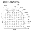
- FIG. 4 In the extended correction amount map creation step, an extended correction amount map ECM that fills the uncorrectable area Anc is created based on the basic correction amount map BCM in FIG.
- the estimated value of the correction amount corresponding to the rotation speed and the load factor is shown for each combination of the rotation speed and the load factor.
- each estimated correction amount data set SCe shows a set of data including correction values for the rotation speed, the load factor, and the correction amount that are specified by different combinations of the rotation speed and the load factor.
- the estimated value of the correction amount is acquired as follows, for example.
- the equivalence line is set for each fixed value of the correction amount, and the difference in the correction amount between the adjacent equivalence lines is (0.2C).
- the distribution of the equal lines in the uncorrectable region Anc can be estimated based on the distribution trend of the equal lines indicated by the solid line.
- the estimated equivalence line is indicated by a two-dot chain line.
- a function having the rotation speed and the load factor as independent variables and the correction amount as a dependent variable is created by curve fitting based on the correction amount data set SC, and the correction amount in the uncorrectable region Anc is estimated based on the function.
- a value may be acquired.
- the correction amount map CM shown in FIG. 4 is created by combining the basic correction amount map BCM and the extended correction amount map ECM. Since the basic correction amount map BCM and the extended correction amount map ECM are set for each reference opening, the correction amount map CM is also set for each reference opening. For this reason, the control device 20 stores a plurality of correction amount maps CM having different reference opening degrees.
- the EGR valve 12 can keep the EGR rate constant even in the operating state where the correction value is not obtained.
- the amount of correction of the opening can be determined.
- the operation state indicates a state specified by the rotation speed and the load factor, and indicates, for example, the magnitude of the differential pressure.
- the control method of the EGR valve opening will be described with reference to FIG.
- the control method for the EGR valve opening degree is based on a plurality of correction amount maps SM obtained by the method for determining the correction amount for the EGR valve opening degree, and specifies the opening amount correction amount corresponding to the operating state, and the EGR rate is constant.
- the opening is controlled so as to be maintained at
- the EGR valve opening control method includes a rotation speed detection step, a load factor detection step, an intake air amount detection step, a correction amount map specifying step, and an opening degree control step.
- FIG. 5 is a block diagram of a configuration related to opening degree control.
- the control device 20 includes a load factor detection unit 201, a correction amount specifying unit 202, and an opening degree control unit 203.
- the rotation speed sensor (rotation speed detector) 21 detects the rotation speed of the engine 1.
- the load factor detector 201 detects the load factor based on the fuel injection amount commanded to the common rail 10.
- the control device 20 controls the engine 1 so as to keep the rotational speed constant by changing the command value of the fuel injection amount in accordance with the fluctuation of the load. For this reason, the control apparatus 20 can grasp
- the air flow meter (intake air amount detection unit) 22 detects the mixed intake air amount passing through the intake pipe 6.
- the mixed intake air amount is the total amount of the intake air amount and the EGR gas. For this reason, the intake air amount can be specified based on the mixed intake amount and the EGR gas.
- the correction amount specifying unit 202 specifies the correction amount corresponding to the reference opening degree, the rotation speed, and the load factor based on the plurality of correction amount maps CM.
- the correction amount specifying step is a two-step process. In the first stage, the correction amount specifying unit 202 specifies a correction amount map whose reference opening is closest to the current value of the opening among the plurality of correction amount maps CM.
- the control device 20 creates a command value for the opening, and the opening of the EGR valve 12 is controlled based on the command value. That is, the current value of the opening is the opening before correction and indicates the command value of the opening at the current time.
- the correction amount map CM corresponding to the third reference opening is specified.
- the correction amount specifying unit 202 specifies a correction amount corresponding to the rotation speed and the load factor based on the specified correction amount map CM.
- the rotation speed and the load factor used for specifying the correction amount are the rotation speed and the load factor detected in the rotation speed detection step and the load factor detection step.
- the opening control unit 203 controls the opening to the target opening corresponding to the specified correction amount and the reference opening.
- the target opening is the sum of the reference opening and the correction amount. In this way, the opening degree of the EGR valve is corrected so as to keep the EGR rate constant.
- the control method for the EGR valve opening according to the present embodiment can correct the opening of the EGR valve so as to keep the EGR rate constant even in an operating state where a correction value is not obtained.
Landscapes
- Engineering & Computer Science (AREA)
- Chemical & Material Sciences (AREA)
- Combustion & Propulsion (AREA)
- Mechanical Engineering (AREA)
- General Engineering & Computer Science (AREA)
- Analytical Chemistry (AREA)
- Exhaust-Gas Circulating Devices (AREA)
- Output Control And Ontrol Of Special Type Engine (AREA)
Abstract
EGR弁開度の補正量の決定方法は、回転数及び負荷率の異なる組合せ毎に得られる補正量に基づいて、開度が基準開度に保たれ且つEGR率が目標EGR率に保たれているときの、回転数、負荷率、及び補正量の相関を示す基本補正量マップBCMを作成する、基本補正量マップ作成工程と、基本補正量マップBCMに含まれる補正量の分布の傾向に基づいて、基本補正量マップBCMに含まれない補正量の分布を推定することによって、基本補正量マップに含まれない補正量の推定値を取得し、開度が基準開度に保たれ且つEGR率が目標EGR率に保たれているときの、回転数、負荷率、及び補正量の推定値の相関を示す拡張補正量マップECMを作成する、拡張補正量マップ作成工程と、を備えている。
Description
本発明は、排気圧と吸気圧との差圧が変動しても、EGR率が所定の目標EGR率に保たれるように、開度を、差圧に対応する目標開度に補正するための補正量を決定する、EGR弁開度の補正量の決定方法に関する。
EGRシステムでは、吸気管と排気管とがEGR管を介して連結されており、EGR管を介して排気ガスが吸気管内に供給される。また、EGR管内には、EGRガス(吸気管内に流入する排気ガス)の流量を制御するためのEGR弁が設けられている。
現在検討されている技術は、排気圧と吸気圧との差圧を検出し、その差圧に応じてEGR弁の開度を補正することによって、差圧の変動によってEGR率が変動することを抑制する。このような技術の一例が、例えば、本出願人による特許文献1に記載の技術である。
ここで、EGR率、EGRガス量、吸入空気量、差圧、及び開度は、次の式(1)、(2)の関係を満たしている。
EGR率=EGRガス量/(吸入空気量+EGRガス量)・・・(1)
EGRガス量=比例定数×差圧×EGR弁の開度・・・(2)
EGR率=EGRガス量/(吸入空気量+EGRガス量)・・・(1)
EGRガス量=比例定数×差圧×EGR弁の開度・・・(2)
EGR率は、吸入空気量、差圧、及びEGR弁の開度を検出することによって、特定される。このため、差圧の変動に応じて開度を変更することによって、EGR率を所定の目標率に保つことが可能である。
EGRガス量は、上述したように、差圧×EGR弁の開度に比例する値として求められている。このため、平均排気圧が平均吸気圧よりも高く、差圧が負の値を取る場合、EGRガス量を求めることができない。
排気ガスの方が吸入空気よりも温度が高いため、通常、排気圧の方が吸気圧よりも高く、吸気管から排気管に吸入空気が逆流しない。一方、ターボチャージャー付のエンジンでは、吸気圧が高められる。この結果、吸気圧が排気圧よりも高い場合が発生する。ここで、吸気圧及び排気圧はそれぞれ、正確には、吸気圧及び排気圧の単位時間当たり平均値である、平均吸気圧及び平均排気圧を指している。吸気圧及び排気圧は、それぞれ吸気弁及び排気弁の開閉に応じて脈動するため、平均吸気圧が平均排気圧よりも高くても、瞬間的に排気圧が吸気圧よりも高くなる場合がある。このため、吸気圧が排気圧よりも高くても、EGR(排気再循環)の実施は可能である。なお、吸入空気が排気管内に流入するのを防止するために、EGR管内には、排気圧が吸気圧よりも高い場合にのみ開くリードバルブが設けられている。
つまり、上述のEGRガス量の決定式(2)は、常に一定の差圧がEGR管内に作用している場合を想定しており、吸気圧及び排気圧の脈動によりリードバルブを介してEGRガスが吸気管内に流入する場合を想定していない。したがって、平均排気圧が平均吸気圧よりも高い場合、EGR弁の開度を補正するための補正量を特定できない。補正量が特定できなければ、差圧の変動によるEGR率の変動を抑制するように、EGR弁の開度を補正することもできない。
そこで、本発明は、平均排気圧が平均吸気圧よりも高い場合の運転状態など、補正値が得られていない運転状態においても、EGR率を一定に保つようにEGR弁の開度の補正量を決定できる、EGR弁開度の補正量の決定方法を提供する。
本発明は、排気圧と吸気圧との差圧が変動しても、差圧、EGR弁の開度、及び吸入空気量に基づいて特定されるEGR率が所定の目標EGR率に保たれるように、開度を、差圧に対応する目標開度に補正するための補正量を決定する、EGR弁開度の補正量の決定方法であって、複数の異なる基準開度毎に設定されるマップであって、開度が基準開度に保たれているときの、エンジンの回転数、エンジンの負荷率、及び差圧の相関を示す差圧マップを作成する、差圧マップ作成工程と、目標開度が、目標EGR率、差圧、及び吸入空気量に基づいて特定されることと、差圧が回転数及び負荷率に基づいて特定されることとを利用して、回転数及び負荷率の異なる組合せ毎に、目標開度と基準開度との差である補正量を算出する、補正量算出工程と、回転数及び負荷率の異なる組合せ毎に得られる補正量に基づいて、開度が基準開度に保たれ且つEGR率が目標EGR率に保たれているときの、回転数、負荷率、及び補正量の相関を示す基本補正量マップを作成する、基本補正量マップ作成工程と、基本補正量マップに含まれる補正量の分布の傾向に基づいて、基本補正量マップに含まれない補正量の分布を推定することによって、基本補正量マップに含まれない補正量の推定値を取得し、開度が基準開度に保たれ且つEGR率が目標EGR率に保たれているときの、回転数、負荷率、及び補正量の推定値の相関を示す拡張補正量マップを作成する、拡張補正量マップ作成工程と、を備えている、EGR弁開度の補正量の決定方法を提供する。
好ましくは、基本補正量マップに含まれる補正量は、差圧がゼロ又は正であるときの回転数及び負荷率の組合せ毎に対応する補正量であり、拡張補正量マップに含まれる補正量は、差圧が負であるときの回転数及び負荷率の組合せ毎に対応する補正量である。
本発明は、回転数を検出する、回転数検出工程と、負荷率を検出する、負荷率検出工程と、吸入空気量を検出する、吸入空気量検出工程と、前記EGR弁開度の補正量の決定方法によって得られる複数の基本補正量マップ及び拡張補正量マップに基づいて、基準開度、回転数、及び負荷率に対応する補正量を特定する、補正量特定工程と、特定された補正量及び基準開度に対応する目標開度に開度を制御する開度制御工程と、を備えている、EGR弁開度の制御方法を提供する。
本発明は、回転数を検出する、回転数検出部と、負荷率を検出する、負荷率検出部と、
吸入空気量を検出する、吸入空気量検出部と、前記EGR弁開度の補正量の決定方法によって得られる複数の基本補正量マップ及び拡張補正量マップに基づいて、基準開度、回転数、及び負荷率に対応する補正量を特定する、補正量マップ特定部と、特定された補正量マップに基づいて、基準開度、回転数、及び負荷率に対応する補正量を特定する、補正量特定部と、特定された補正量及び基準開度に対応する目標開度に開度を制御する開度制御部と、を備えている、エンジンを提供する。
吸入空気量を検出する、吸入空気量検出部と、前記EGR弁開度の補正量の決定方法によって得られる複数の基本補正量マップ及び拡張補正量マップに基づいて、基準開度、回転数、及び負荷率に対応する補正量を特定する、補正量マップ特定部と、特定された補正量マップに基づいて、基準開度、回転数、及び負荷率に対応する補正量を特定する、補正量特定部と、特定された補正量及び基準開度に対応する目標開度に開度を制御する開度制御部と、を備えている、エンジンを提供する。
本発明に係るEGR弁開度の補正量の決定方法は、補正値の推定値に基づいて補正量を特定できるので、平均排気圧が平均吸気圧よりも高い場合の運転状態など、補正値が得られていない運転状態においても、EGR率を一定に保つようにEGR弁12の開度の補正量を決定できる。
本発明に係るEGR弁開度の制御方法及びエンジンは、平均排気圧が平均吸気圧よりも高い場合の運転状態など、補正値が得られていない運転状態においても、EGR率を一定に保つようにEGR弁の開度を補正できる。
図1は、エンジン1の構成図である。エンジン1は、シリンダヘッド2、シリンダブロック3、複数のシリンダ4、クランクシャフト5、吸気管6、排気管7、排気再循環装置(以下、EGR装置)8、ターボチャージャー9、及びコモンレール式燃料噴射装置(以下、コモンレール)10を備えている。
EGR装置8は、EGR管11、EGR弁12、及びリードバルブ13を備えている。EGR管11は、排気管7と吸気管6とを連通する。EGR弁12及びリードバルブ13は、EGR管11内に配置されている。EGR弁12は、自らの開度を変更することによって、EGR管11内を通過する排気ガスの流量を変更する。リードバルブ13は、EGR管11内において、排気管7から吸気管6への排気ガスの流れのみを許容し、吸気管6から排気管7への排気ガスの流れを禁止する。以下、EGR管11を通過して排気管7から吸気管6へ流れる排気ガスを、EGRガスと称する。
また、エンジン1は、制御のための構成として、制御装置20、回転数センサ21、及びエアフロメーター22を備えている。回転数センサ21は、クランクシャフト5の回転数を検出する。エアフロメーター22は、吸気管6を通過する混合吸気量を検出する。ここで、エアフロメーター22は吸気管6内においてEGR管11の出口よりも下流側に配置されている。このため、混合吸気量は、外気にEGRガスが混入されたガス量であり、つまり吸入空気量とEGRガス量との合計量を指している。制御装置20は、回転数センサ21及びエアフロメーター22の検出情報を取得できる。また、制御装置20は、コモンレール10及びEGR弁12を制御する。
制御装置20は、排気圧と吸気圧との差圧が変動しても、EGR率が所定の目標率に保たれるように、差圧に対応する目標開度に、EGR弁12の開度を制御するように構成されている。制御装置20は、EGR弁12の開度を目標開度に補正するための補正量マップCMを記憶している。補正量マップCMは、後述のEGR弁開度の補正量の決定方法によって作成される。
図2~図4を参照して、EGR弁開度の補正量の決定方法を説明する。この補正量の決定方法は、差圧マップ作成工程、補正量算出工程、基本補正量マップ作成工程、及び拡張補正量マップ作成工程を、備えている。
補正量の決定方法は、EGR率が所定の目標EGR率に保たれるように、目標EGR率を実現する目標開度を得るための補正量を決定する。ここで、補正量は、目標開度と所定の基準開度との差である。また、基準開度の大きさに応じて、差圧、EGR弁の開度、及び吸入空気量に基づいて特定されるEGR率が変化する。EGR率に応じて排気圧が変化するため、差圧も変化し、差圧に応じて設定される補正量も変化する。つまり、目標EGR率の大きさだけでなく基準開度の大きさによって、補正量の大きさが異なっている。基準開度毎に補正量が設定されるため、異なる基準開度の数を増やせば、それだけ補正の精度は向上する。しかし、基準開度毎に多量の補正量のデータが設定されるため、制御装置20に記憶させるデータ量が増大する。このため、基準開度の数は、一定数に限定されている。
本実施形態では、所定の基準開度として、第1~第6基準開度(%)が設定されており、0%、20%、40%、60%、80%、及び100%からなっている。第n基準開度は、第1~第6基準開度のいずれか1つを指している。基準開度毎に、後述の差圧マップ及び補正量マップCMが設定されている。
(差圧マップ作成工程)
図2は、開度が第n基準開度に保たれているときに、回転数、負荷率、及び差圧の相関を示す差圧マップを示す図である。図2において、横軸はエンジン1の回転数を示しており、縦軸はエンジン1の負荷率を示している。負荷率は、エンジン1の1回転当たりの燃料噴射量に関する割合であって、設定可能な最大の燃料噴射量に対する現在の燃料噴射量の割合を示している。ここで、エンジン1は回転数を一定に保つように制御されるため、エンジン1に掛かる負荷の増大に応じて、燃料噴射量が増大する。差圧は、排気圧から吸気圧を引いて得られる圧力差を示している。
図2は、開度が第n基準開度に保たれているときに、回転数、負荷率、及び差圧の相関を示す差圧マップを示す図である。図2において、横軸はエンジン1の回転数を示しており、縦軸はエンジン1の負荷率を示している。負荷率は、エンジン1の1回転当たりの燃料噴射量に関する割合であって、設定可能な最大の燃料噴射量に対する現在の燃料噴射量の割合を示している。ここで、エンジン1は回転数を一定に保つように制御されるため、エンジン1に掛かる負荷の増大に応じて、燃料噴射量が増大する。差圧は、排気圧から吸気圧を引いて得られる圧力差を示している。
なお、本明細書において、吸気圧及び排気圧はそれぞれ、吸気圧及び排気圧の単位時間当たり平均値である、平均吸気圧及び平均排気圧を指している。
差圧マップ作成工程は、図2に示される差圧マップを作成する。図2において、回転数及び負荷率の異なる組合せ毎に、回転数及び負荷率に対応する差圧が得られている。図2において、各差圧データセットSDは、回転数及び負荷率の異なる組合せによって特定される、回転数、負荷率、及び差圧よりなる一組のデータを示している。ここで、エンジン1の特性により、実験的に、回転数及び負荷率に対応する差圧を検出することができる。
図2には、複数の等圧線が記されている。等圧線は、差圧マップ上で同一の差圧を示す座標(回転数、負荷率)の集まりである。各等圧線における差圧の大きさは、例えば、-1D、0、+1~+7Dのいずれか1つである。符号(D)は、一定量の差圧の絶対値を示している。符号(+)及び(-)は、差圧が正であるか負であるかを示している。符号(D)に付されている数字(2)等は、一定量の差圧に対する比率を示している。+4Dの差圧の大きさは、+2Dの差圧の2倍である。
複数の等圧線は、差圧の分布の傾向を示している。図2の左上の領域から右の領域に向けて、差圧が上昇している。図2の左上の領域は、差圧が負になっている負圧領域Amであり、他の領域は、差圧が正になっている正圧領域Apである。
(補正量算出工程)
補正量算出工程は、回転数及び負荷率の異なる組合せ毎に、目標開度と基準開度との差である補正量を算出する。補正量は、式(3)に示すように、目標開度と基準開度との差である。つまり、補正後の開度としての目標開度は、式(4)に示すように、基準開度と補正量との和である。
補正量=目標開度-基準開度・・・(3)
目標開度(補正後の開度)=基準開度+補正量・・・(4)
補正量算出工程は、回転数及び負荷率の異なる組合せ毎に、目標開度と基準開度との差である補正量を算出する。補正量は、式(3)に示すように、目標開度と基準開度との差である。つまり、補正後の開度としての目標開度は、式(4)に示すように、基準開度と補正量との和である。
補正量=目標開度-基準開度・・・(3)
目標開度(補正後の開度)=基準開度+補正量・・・(4)
ここで、EGR率、EGRガス量、吸入空気量、差圧、及び開度は、次の式(1)、(2)の関係を満たしている。
EGR率=EGRガス量/(吸入空気量+EGRガス量)・・・(1)
EGRガス量=比例定数×差圧×EGR弁の開度・・・(2)
EGR率=EGRガス量/(吸入空気量+EGRガス量)・・・(1)
EGRガス量=比例定数×差圧×EGR弁の開度・・・(2)
開度が、EGR率、差圧、及び吸入空気量に基づいて特定されるので、目標開度は、目標EGR率、差圧、及び吸入空気量に基づいて特定される。したがって、目標開度と基準開度との差である補正量が、基準開度、目標EGR率、差圧、及び吸入空気量に基づいて特定される。また、図2の補正マップに示されるように、差圧は、回転数及び負荷率に基づいて特定される。このため、補正量は、基準開度、目標EGR率、回転数、負荷率、及び吸入空気量に基づいて特定される。基準開度、目標EGR率、及び吸入空気量は、運転条件等によって特定される定数であり、回転数、負荷率、及び補正量が変数である。このため、補正量算出工程において、回転数及び負荷率の異なる組合せ毎に、補正量が得られている。
ただし、差圧が負である場合、補正量を、基準開度、目標EGR率、回転数、負荷率、及び吸入空気量に基づいて特定できない。このため、負圧領域Am内に含まれる回転数及び負荷率の組合せからは、補正量が得られない。
(基本補正量マップ作成工程)
基本補正量マップ作成工程は、例えば図3に示される基本補正量マップBCMを作成する。基本補正量マップBCMは、EGR率が目標EGR率に保たれているときの、回転数、負荷率、及び補正量の相関を示している。基本補正量マップBCMは、回転数及び負荷率の異なる組合せ毎に得られる補正量に基づいて作成される。また、異なる基準開度毎に、異なる基本補正量マップBCMが作成される。
基本補正量マップ作成工程は、例えば図3に示される基本補正量マップBCMを作成する。基本補正量マップBCMは、EGR率が目標EGR率に保たれているときの、回転数、負荷率、及び補正量の相関を示している。基本補正量マップBCMは、回転数及び負荷率の異なる組合せ毎に得られる補正量に基づいて作成される。また、異なる基準開度毎に、異なる基本補正量マップBCMが作成される。
図3は、開度が第n基準開度に保たれ且つEGR率が目標EGR率に保たれているときの、回転数、負荷率、及び補正量の相関を示す基本補正量マップBCMを示す図である。図3において、横軸は回転数を示しており、縦軸は負荷率を示している。図3において、回転数及び負荷率の異なる組合せ毎に、回転数及び負荷率に対応する補正量が示されている。図3において、各補正量データセットSCは、回転数及び負荷率の異なる組合せによって特定される、回転数、負荷率、及び補正量よりなる一組のデータを示している。
図3には、複数の補正量の等量線が記されている。等量線は、基本補正量マップBCM上で同一の補正量を示す座標(回転数、負荷率)の集まりである。等量線における補正量の大きさは、例えば、0.2C、0.4C、0.6C~1.6Cのいずれか1つである。ここで、等量線における補正量の大きさは、0.2C毎に等間隔に設定されている。符号(C)は、一定量の補正量を示している。符号(C)に付されている数字(2)等は、一定量の補正量に対する比率を示している。0.4Cの補正量の大きさは、1.0Cの補正量の0.4倍である。つまり、任意の補正量を基準にして、他の補正量が、その基準の補正量に対する比率を用いて表現されている。
複数の等量線は、補正量の分布の傾向を示している。図3の上の領域から下の領域に向けて、補正量が増加している。
図2の差圧マップ及び図3の基本補正量マップBCMは、共に、回転数及び負荷率を要素としているので、差圧マップ及び基本補正量マップBCMは原則として互いに対応している。しかし、上述したように、負圧領域Amでは補正量が得られていない。このため、図3の基本補正量マップBCMは、負圧領域Amに対応する補正不能領域Ancを含んでいない。図3の基本補正量マップBCMは、図2の差圧マップと比べて、左上の領域が欠けている。
(拡張補正量マップ作成工程)
拡張補正量マップ作成工程は、開度が第n基準開度に保たれ且つEGR率が目標EGR率に保たれているときの、回転数、負荷率、及び補正量の推定値の相関を示す拡張補正量マップECMを作成する。ここで、上述の基本補正量マップBCMは、図2の差圧マップの正圧領域Apに対応する領域における、回転数、負荷率、及び補正量の相関を示している。このため、基本補正量マップBCMは、負圧領域Amに対応する領域における、回転数、負荷率、及び補正量の相関を示していない。そこで、負圧領域Amに対応する領域における、回転数、負荷率、及び補正量の相関を示すマップとして、拡張補正量マップECMが作成される。ただし、負圧領域Amにおいて補正量が得られないため、拡張補正量マップECMでは、補正量の代わりに、補正量の推定値が用いられている。補正量の推定値は、基本補正量マップBCMに含まれる補正量の分布の傾向に基づいて、基本補正量マップBCMに含まれない補正量の分布を推定することによって、取得される。
拡張補正量マップ作成工程は、開度が第n基準開度に保たれ且つEGR率が目標EGR率に保たれているときの、回転数、負荷率、及び補正量の推定値の相関を示す拡張補正量マップECMを作成する。ここで、上述の基本補正量マップBCMは、図2の差圧マップの正圧領域Apに対応する領域における、回転数、負荷率、及び補正量の相関を示している。このため、基本補正量マップBCMは、負圧領域Amに対応する領域における、回転数、負荷率、及び補正量の相関を示していない。そこで、負圧領域Amに対応する領域における、回転数、負荷率、及び補正量の相関を示すマップとして、拡張補正量マップECMが作成される。ただし、負圧領域Amにおいて補正量が得られないため、拡張補正量マップECMでは、補正量の代わりに、補正量の推定値が用いられている。補正量の推定値は、基本補正量マップBCMに含まれる補正量の分布の傾向に基づいて、基本補正量マップBCMに含まれない補正量の分布を推定することによって、取得される。
図4は、開度が第n基準開度に保たれ且つEGR率が目標EGR率に保たれているときの、回転数、負荷率、及び補正量の相関を示す基本補正量マップBCMを示す図である。拡張補正量マップ作成工程は、図3の基本補正量マップBCMに基づいて、補正不能領域Ancを埋める拡張補正量マップECMを作成する。図4において、回転数及び負荷率の異なる組合せ毎に、回転数及び負荷率に対応する補正量の推定値が示されている。図4において、各推定補正量データセットSCeは、回転数及び負荷率の異なる組合せによって特定される、回転数、負荷率、及び補正量の補正値よりなる一組のデータを示している。
補正量の推定値は、例えば、次のようにして取得される。図3において、等量線は、補正量の一定値毎に設定されており、隣り合う等量線間における補正量の差は、(0.2C)である。このため、実線で示される等量線の分布の傾向に基づいて、補正不能領域Ancにおける等量線の分布を推定できる。図3において、推定された等量線が、二点鎖線により示されている。この結果、補正不能領域Ancにおける補正量の推定値が取得され、拡張補正量マップECMが作成される。あるいは、補正量データセットSCに基づく曲線当てはめにより、回転数及び負荷率を独立変数とし、補正量を従属変数とする関数を作成し、該関数に基づいて、補正不能領域Ancにおける補正量の推定値を取得しても良い。
図4に示される補正量マップCMは、基本補正量マップBCM及び拡張補正量マップECMを合わせることによって作成されている。基本補正量マップBCM及び拡張補正量マップECMが基準開度毎に設定されるため、補正量マップCMも基準開度毎に設定されている。このため、制御装置20は、複数の基準開度の異なる補正量マップCMを記憶している。
本実施形態に係る補正量の決定方法は、補正値の推定値に基づいて補正量を特定できるので、補正値が得られていない運転状態においても、EGR率を一定に保つようにEGR弁12の開度の補正量を決定できる。ここで、運転状態は、回転数及び負荷率によって特定される状態を指しており、例えば差圧の大きさを指している。
図5を参照して、EGR弁開度の制御方法を説明する。EGR弁開度の制御方法は、EGR弁開度の補正量の決定方法によって得られる複数の補正量マップSMに基づいて、運転状態に対応する開度の補正量を特定し、EGR率が一定に保たれるように開度を制御する。
EGR弁開度の制御方法は、回転数検出工程、負荷率検出工程、吸入空気量検出工程、補正量マップ特定工程、及び開度制御工程を、備えている。
図5は、開度の制御に関係する構成のブロック図である。図5において、制御装置20は、負荷率検出部201、補正量特定部202、及び開度制御部203を備えている。
回転数検出工程において、回転数センサ(回転数検出部)21は、エンジン1の回転数を検出する。
負荷率検出工程において、負荷率検出部201は、コモンレール10に指令する燃料噴射量に基づいて、負荷率を検出する。上述したように、制御装置20は、負荷の変動に応じて燃料噴射量の指令値を変更することによって、回転数を一定に保つようにエンジン1を制御する。このため、制御装置20は、燃料噴射量の指令値の変動に基づいて、負荷の変動を把握できる。
吸入空気量検出工程において、エアフロメーター(吸入空気量検出部)22は、吸気管6を通過する混合吸気量を検出する。ここで、上述したように、混合吸気量は、吸入空気量とEGRガスとの合計量である。このため、吸入空気量を、混合吸入量及びEGRガスに基づいて特定できる。
補正量特定工程において、補正量特定部202は、複数の補正量マップCMに基づいて、基準開度、回転数、及び負荷率に対応する補正量を特定する。補正量特定工程は、2段階の処理からなっている。第1段階では、補正量特定部202は、複数の補正量マップCMのうち、基準開度が開度の現在値に最も近い補正量マップを特定する。ここで、制御装置20が開度の指令値を作成し、その指令値に基づいてEGR弁12の開度が制御される。つまり、開度の現在値は、補正前の開度であって、現時点における開度の指令値を指している。例えば、開度の現在値が35%であるとき、開度の現在値に最も近い基準開度は、第1~第6基準開度のうち、第3基準開度の40%である。この場合、第3基準開度に対応する補正量マップCMが、特定される。第2段階では、補正量特定部202は、特定された補正量マップCMに基づいて、回転数及び負荷率に対応する補正量を特定する。ここで、補正量の特定に用いられる回転数及び負荷率は、回転数検出工程及び負荷率検出工程において検出された回転数及び負荷率である。
開度制御工程において、開度制御部203は、特定された補正量及び基準開度に対応する目標開度に、開度を制御する。上述の式(4)に示されるように、目標開度は、基準開度と補正量との和である。このようにして、EGR率を一定に保つようにEGR弁の開度が補正される。
本実施形態に係るEGR弁開度の制御方法は、補正値が得られていない運転状態においても、EGR率を一定に保つようにEGR弁の開度を補正できる。
1 エンジン
12 EGR弁
20 制御装置
21 回転数センサ(回転数検出部)
22 エアフロメーター(吸入空気量検出部)
201 負荷率検出部
202 補正量特定部
203 開度制御部
BCM 基本補正量マップ
ECM 拡張補正量マップ
Anc 補正不能領域
12 EGR弁
20 制御装置
21 回転数センサ(回転数検出部)
22 エアフロメーター(吸入空気量検出部)
201 負荷率検出部
202 補正量特定部
203 開度制御部
BCM 基本補正量マップ
ECM 拡張補正量マップ
Anc 補正不能領域
Claims (4)
- 排気圧と吸気圧との差圧が変動しても、差圧、EGR弁の開度、及び吸入空気量に基づいて特定されるEGR率が所定の目標EGR率に保たれるように、開度を、差圧に対応する目標開度に補正するための補正量を決定する、EGR弁開度の補正量の決定方法であって、
複数の異なる基準開度毎に設定されるマップであって、開度が基準開度に保たれているときの、エンジンの回転数、エンジンの負荷率、及び差圧の相関を示す差圧マップを作成する、差圧マップ作成工程と、
目標開度が、目標EGR率、差圧、及び吸入空気量に基づいて特定されることと、差圧が回転数及び負荷率に基づいて特定されることとを利用して、回転数及び負荷率の異なる組合せ毎に、目標開度と基準開度との差である補正量を算出する、補正量算出工程と、
回転数及び負荷率の異なる組合せ毎に得られる補正量に基づいて、開度が基準開度に保たれ且つEGR率が目標EGR率に保たれているときの、回転数、負荷率、及び補正量の相関を示す基本補正量マップを作成する、基本補正量マップ作成工程と、
基本補正量マップに含まれる補正量の分布の傾向に基づいて、基本補正量マップに含まれない補正量の分布を推定することによって、基本補正量マップに含まれない補正量の推定値を取得し、開度が基準開度に保たれ且つEGR率が目標EGR率に保たれているときの、回転数、負荷率、及び補正量の推定値の相関を示す拡張補正量マップを作成する、拡張補正量マップ作成工程と、
を備えている、EGR弁開度の補正量の決定方法。 - 基本補正量マップに含まれる補正量は、差圧がゼロ又は正であるときの回転数及び負荷率の組合せ毎に対応する補正量であり、
拡張補正量マップに含まれる補正量は、差圧が負であるときの回転数及び負荷率の組合せ毎に対応する補正量である、
請求項1に記載の、EGR弁開度の補正量の決定方法。 - 回転数を検出する、回転数検出工程と、
負荷率を検出する、負荷率検出工程と、
吸入空気量を検出する、吸入空気量検出工程と、
請求項1又は2に記載のEGR弁開度の補正量の決定方法によって得られる複数の基本補正量マップ及び拡張補正量マップに基づいて、基準開度、回転数、及び負荷率に対応する補正量を特定する、補正量特定工程と、
特定された補正量及び基準開度に対応する目標開度に開度を制御する開度制御工程と、
を備えている、EGR弁開度の制御方法。 - 回転数を検出する、回転数検出部と、
負荷率を検出する、負荷率検出部と、
吸入空気量を検出する、吸入空気量検出部と、
請求項1又は2に記載のEGR弁開度の補正量の決定方法によって得られる複数の基本補正量マップ及び拡張補正量マップに基づいて、基準開度、回転数、及び負荷率に対応する補正量を特定する、補正量マップ特定部と、
特定された補正量マップに基づいて、基準開度、回転数、及び負荷率に対応する補正量を特定する、補正量特定部と、
特定された補正量及び基準開度に対応する目標開度に開度を制御する開度制御部と、
を備えている、エンジン。
Priority Applications (2)
| Application Number | Priority Date | Filing Date | Title |
|---|---|---|---|
| EP12759890.2A EP2687710A4 (en) | 2011-03-18 | 2012-03-16 | METHOD FOR DETERMINING THE IMPORTANCE OF CORRECTING OPENING DEGREE OF EGR VALVE, METHOD OF CONTROLLING EGR VALVE OPENING DEGREE AND MOTOR |
| US14/005,709 US9243590B2 (en) | 2011-03-18 | 2012-03-16 | Method of determining correction amount of opening degree of EGR valve, method of controlling opening degree of EGR valve, and engine |
Applications Claiming Priority (2)
| Application Number | Priority Date | Filing Date | Title |
|---|---|---|---|
| JP2011-060284 | 2011-03-18 | ||
| JP2011060284A JP5793320B2 (ja) | 2011-03-18 | 2011-03-18 | エンジン |
Publications (1)
| Publication Number | Publication Date |
|---|---|
| WO2012128224A1 true WO2012128224A1 (ja) | 2012-09-27 |
Family
ID=46879371
Family Applications (1)
| Application Number | Title | Priority Date | Filing Date |
|---|---|---|---|
| PCT/JP2012/056914 Ceased WO2012128224A1 (ja) | 2011-03-18 | 2012-03-16 | Egr弁開度の補正量の決定方法、egr弁開度の制御方法、及びエンジン |
Country Status (4)
| Country | Link |
|---|---|
| US (1) | US9243590B2 (ja) |
| EP (1) | EP2687710A4 (ja) |
| JP (1) | JP5793320B2 (ja) |
| WO (1) | WO2012128224A1 (ja) |
Cited By (1)
| Publication number | Priority date | Publication date | Assignee | Title |
|---|---|---|---|---|
| US20140224231A1 (en) * | 2013-02-13 | 2014-08-14 | Woodward, Inc. | Controlling an Exhaust Gas Recirculation (EGR) Valve |
Families Citing this family (7)
| Publication number | Priority date | Publication date | Assignee | Title |
|---|---|---|---|---|
| JP6075852B2 (ja) * | 2012-12-25 | 2017-02-08 | ヤンマー株式会社 | エンジン |
| JP6301061B2 (ja) * | 2013-02-18 | 2018-03-28 | 株式会社ミクニ | バルブ制御装置及びバルブ制御方法 |
| JP6523104B2 (ja) * | 2015-08-25 | 2019-05-29 | ヤンマー株式会社 | エンジン及びegr還流量計算方法 |
| MY176701A (en) * | 2016-09-07 | 2020-08-19 | Nissan Motor | Engine control method and control device |
| MX2019002802A (es) | 2016-09-09 | 2019-07-15 | Nissan Motor | Metodo de control y dispositivo de control para motor de combustion interna. |
| FR3107565B1 (fr) | 2020-02-26 | 2024-02-16 | Psa Automobiles Sa | Procédé de correction en phase transitoire des paramètres d’injection de carburant d’un moteur thermique muni d’une vanne egr |
| CN119353115B (zh) * | 2024-10-17 | 2025-09-30 | 东风汽车集团股份有限公司 | 一种加快打开混合阀开度请求控制方法及系统 |
Citations (6)
| Publication number | Priority date | Publication date | Assignee | Title |
|---|---|---|---|---|
| JPS62298654A (ja) * | 1986-06-17 | 1987-12-25 | Toyota Motor Corp | 内燃機関の排気還流制御装置 |
| JPH04252849A (ja) * | 1991-01-29 | 1992-09-08 | Nippon Soken Inc | 内燃機関のegr弁制御装置 |
| JPH1162720A (ja) * | 1997-08-08 | 1999-03-05 | Nissan Motor Co Ltd | エンジンのegr制御装置 |
| JP2000356158A (ja) * | 1999-06-15 | 2000-12-26 | Nissan Motor Co Ltd | エンジンの制御装置 |
| JP2010144700A (ja) * | 2008-12-22 | 2010-07-01 | Ud Trucks Corp | 排気還流装置 |
| JP2010169472A (ja) | 2009-01-21 | 2010-08-05 | Konica Minolta Opto Inc | 干渉測定方法 |
Family Cites Families (19)
| Publication number | Priority date | Publication date | Assignee | Title |
|---|---|---|---|---|
| JPS5364123A (en) | 1976-11-19 | 1978-06-08 | Nissan Motor Co Ltd | Exhaust reflux controller for internal combustion engines |
| JP3365197B2 (ja) | 1996-03-21 | 2003-01-08 | 日産自動車株式会社 | 内燃機関のegr制御装置 |
| JPH11182356A (ja) * | 1997-12-15 | 1999-07-06 | Nissan Motor Co Ltd | 内燃機関のegr制御装置 |
| JP3551024B2 (ja) * | 1998-06-12 | 2004-08-04 | トヨタ自動車株式会社 | 内燃機関の排気ガス還流制御装置 |
| JP3998861B2 (ja) * | 1999-06-16 | 2007-10-31 | 株式会社小松製作所 | 排気還流装置およびその制御方法 |
| JP4004193B2 (ja) * | 1999-10-06 | 2007-11-07 | 日野自動車株式会社 | ターボ過給機付エンジンの排ガス再循環装置 |
| US6415776B1 (en) * | 2000-08-25 | 2002-07-09 | Ford Global Technologies, Inc. | EGR system using pressure-based feedback control |
| US6480782B2 (en) * | 2001-01-31 | 2002-11-12 | Cummins, Inc. | System for managing charge flow and EGR fraction in an internal combustion engine |
| US6880524B2 (en) * | 2002-04-15 | 2005-04-19 | Ford Global Technologies, Llc | Diesel EGR control |
| JP2005233000A (ja) * | 2004-02-17 | 2005-09-02 | Nissan Motor Co Ltd | 内燃機関の排気還流装置 |
| JP4320684B2 (ja) * | 2007-06-08 | 2009-08-26 | トヨタ自動車株式会社 | 内燃機関の排気還流装置 |
| US7739027B2 (en) * | 2007-08-17 | 2010-06-15 | Gm Global Technology Operations, Inc. | Method and apparatus for monitoring an EGR valve in an internal combustion engine |
| JP2010084519A (ja) | 2008-09-29 | 2010-04-15 | Yanmar Co Ltd | エンジン |
| US8346462B2 (en) * | 2009-08-28 | 2013-01-01 | Toyota Jidosha Kabushiki Kaisha | Malfunction detection apparatus and malfunction detection method for an EGR system |
| JP5075229B2 (ja) * | 2010-06-18 | 2012-11-21 | 本田技研工業株式会社 | 内燃機関のegr制御装置 |
| JP5632223B2 (ja) | 2010-07-28 | 2014-11-26 | ヤンマー株式会社 | エンジン装置の排気ガス再循環システム |
| EP2604834A1 (en) * | 2010-08-10 | 2013-06-19 | Toyota Jidosha Kabushiki Kaisha | Control device for internal combustion engine |
| US9181905B2 (en) * | 2011-09-25 | 2015-11-10 | Cummins Inc. | System for controlling an air handling system including an electric pump-assisted exhaust gas recirculation |
| JP5944249B2 (ja) * | 2012-07-06 | 2016-07-05 | 本田技研工業株式会社 | 内燃機関の内部egr量算出装置 |
-
2011
- 2011-03-18 JP JP2011060284A patent/JP5793320B2/ja not_active Expired - Fee Related
-
2012
- 2012-03-16 US US14/005,709 patent/US9243590B2/en not_active Expired - Fee Related
- 2012-03-16 EP EP12759890.2A patent/EP2687710A4/en not_active Withdrawn
- 2012-03-16 WO PCT/JP2012/056914 patent/WO2012128224A1/ja not_active Ceased
Patent Citations (6)
| Publication number | Priority date | Publication date | Assignee | Title |
|---|---|---|---|---|
| JPS62298654A (ja) * | 1986-06-17 | 1987-12-25 | Toyota Motor Corp | 内燃機関の排気還流制御装置 |
| JPH04252849A (ja) * | 1991-01-29 | 1992-09-08 | Nippon Soken Inc | 内燃機関のegr弁制御装置 |
| JPH1162720A (ja) * | 1997-08-08 | 1999-03-05 | Nissan Motor Co Ltd | エンジンのegr制御装置 |
| JP2000356158A (ja) * | 1999-06-15 | 2000-12-26 | Nissan Motor Co Ltd | エンジンの制御装置 |
| JP2010144700A (ja) * | 2008-12-22 | 2010-07-01 | Ud Trucks Corp | 排気還流装置 |
| JP2010169472A (ja) | 2009-01-21 | 2010-08-05 | Konica Minolta Opto Inc | 干渉測定方法 |
Non-Patent Citations (1)
| Title |
|---|
| See also references of EP2687710A4 * |
Cited By (3)
| Publication number | Priority date | Publication date | Assignee | Title |
|---|---|---|---|---|
| US20140224231A1 (en) * | 2013-02-13 | 2014-08-14 | Woodward, Inc. | Controlling an Exhaust Gas Recirculation (EGR) Valve |
| WO2014126781A1 (en) * | 2013-02-13 | 2014-08-21 | Woodward, Inc. | Controlling an exhaust gas recirculation (egr) valve |
| CN105051352A (zh) * | 2013-02-13 | 2015-11-11 | 伍德沃德有限公司 | 控制废气再循环(egr)的阀 |
Also Published As
| Publication number | Publication date |
|---|---|
| US9243590B2 (en) | 2016-01-26 |
| US20140048051A1 (en) | 2014-02-20 |
| EP2687710A1 (en) | 2014-01-22 |
| JP5793320B2 (ja) | 2015-10-14 |
| EP2687710A4 (en) | 2014-09-03 |
| JP2012193723A (ja) | 2012-10-11 |
Similar Documents
| Publication | Publication Date | Title |
|---|---|---|
| JP5793320B2 (ja) | エンジン | |
| CN103900646B (zh) | 流量运算装置以及流量控制装置 | |
| EP2187026B1 (en) | Controller of internal combustion engine | |
| US8028569B2 (en) | Method and device for adapting the efficiency of a cooler in the return circuit of exhaust gas in an internal combustion engine | |
| US6636796B2 (en) | Method and system for engine air-charge estimation | |
| JP2011185263A (ja) | ターボチャージャ付きエンジンの制御装置 | |
| US11274621B2 (en) | Air flow measurement device | |
| RU2503841C2 (ru) | Способ и система управления устройством управления текучей средой на основе изучения датчика положения | |
| US20130131955A1 (en) | Systems and methods for correcting mass airflow sensor drift | |
| JP2002372446A (ja) | 質量流量に影響する制御システムの制御および/または診断のための方法及び装置 | |
| EP2543857A1 (en) | Systems for evaluating possible abnormality in an engine | |
| KR101981881B1 (ko) | 센서를 사용하지 않고 압력 검출 정확도를 증가시키는 방법 | |
| JP2005146927A (ja) | 圧縮機の制御装置、タービンシステム、圧縮機の制御方法 | |
| JP2016065484A (ja) | スロットル上流圧力の推定装置 | |
| JP5898118B2 (ja) | センサ制御装置、センサ制御システムおよびセンサ制御方法 | |
| JP6922398B2 (ja) | ピストン温度推定装置及びピストン温度推定方法 | |
| KR101998932B1 (ko) | 엔진 | |
| JP2017110514A (ja) | 燃料タンクシステム | |
| CN107532534A (zh) | 用于燃料输送系统的反馈控制方法 | |
| JP2017125473A (ja) | 燃料供給装置 | |
| US6779509B1 (en) | Throttle valve control apparatus | |
| CN106795824A (zh) | 具有改进的丰度控制的机动车辆的燃烧式发动机 | |
| JP2006343136A (ja) | 水蒸気分圧検出装置、エンジンの吸気流量検出装置およびコレクタ内圧検出装置 | |
| JP2013079613A (ja) | 内燃機関の吸気パラメータ算出装置 | |
| US20120253638A1 (en) | Method for adapting a fuel/air mixture for an internal combustion engine |
Legal Events
| Date | Code | Title | Description |
|---|---|---|---|
| 121 | Ep: the epo has been informed by wipo that ep was designated in this application |
Ref document number: 12759890 Country of ref document: EP Kind code of ref document: A1 |
|
| NENP | Non-entry into the national phase |
Ref country code: DE |
|
| REEP | Request for entry into the european phase |
Ref document number: 2012759890 Country of ref document: EP |
|
| WWE | Wipo information: entry into national phase |
Ref document number: 2012759890 Country of ref document: EP |
|
| WWE | Wipo information: entry into national phase |
Ref document number: 14005709 Country of ref document: US |