WO2012128330A1 - 脱硫排水からの脱水濾液の噴霧乾燥装置、排ガス処理システム及び方法 - Google Patents
脱硫排水からの脱水濾液の噴霧乾燥装置、排ガス処理システム及び方法 Download PDFInfo
- Publication number
- WO2012128330A1 WO2012128330A1 PCT/JP2012/057389 JP2012057389W WO2012128330A1 WO 2012128330 A1 WO2012128330 A1 WO 2012128330A1 JP 2012057389 W JP2012057389 W JP 2012057389W WO 2012128330 A1 WO2012128330 A1 WO 2012128330A1
- Authority
- WO
- WIPO (PCT)
- Prior art keywords
- exhaust gas
- spray
- dehydrated filtrate
- drying
- desulfurization
- Prior art date
- Legal status (The legal status is an assumption and is not a legal conclusion. Google has not performed a legal analysis and makes no representation as to the accuracy of the status listed.)
- Ceased
Links
Images

Classifications
-
- B—PERFORMING OPERATIONS; TRANSPORTING
- B01—PHYSICAL OR CHEMICAL PROCESSES OR APPARATUS IN GENERAL
- B01D—SEPARATION
- B01D53/00—Separation of gases or vapours; Recovering vapours of volatile solvents from gases; Chemical or biological purification of waste gases, e.g. engine exhaust gases, smoke, fumes, flue gases, aerosols
- B01D53/34—Chemical or biological purification of waste gases
- B01D53/46—Removing components of defined structure
- B01D53/48—Sulfur compounds
- B01D53/50—Sulfur oxides
-
- B—PERFORMING OPERATIONS; TRANSPORTING
- B01—PHYSICAL OR CHEMICAL PROCESSES OR APPARATUS IN GENERAL
- B01D—SEPARATION
- B01D1/00—Evaporating
- B01D1/16—Evaporating by spraying
- B01D1/18—Evaporating by spraying to obtain dry solids
-
- B—PERFORMING OPERATIONS; TRANSPORTING
- B01—PHYSICAL OR CHEMICAL PROCESSES OR APPARATUS IN GENERAL
- B01D—SEPARATION
- B01D53/00—Separation of gases or vapours; Recovering vapours of volatile solvents from gases; Chemical or biological purification of waste gases, e.g. engine exhaust gases, smoke, fumes, flue gases, aerosols
- B01D53/34—Chemical or biological purification of waste gases
- B01D53/46—Removing components of defined structure
- B01D53/48—Sulfur compounds
- B01D53/50—Sulfur oxides
- B01D53/501—Sulfur oxides by treating the gases with a solution or a suspension of an alkali or earth-alkali or ammonium compound
- B01D53/504—Sulfur oxides by treating the gases with a solution or a suspension of an alkali or earth-alkali or ammonium compound characterised by a specific device
-
- B—PERFORMING OPERATIONS; TRANSPORTING
- B01—PHYSICAL OR CHEMICAL PROCESSES OR APPARATUS IN GENERAL
- B01D—SEPARATION
- B01D53/00—Separation of gases or vapours; Recovering vapours of volatile solvents from gases; Chemical or biological purification of waste gases, e.g. engine exhaust gases, smoke, fumes, flue gases, aerosols
- B01D53/34—Chemical or biological purification of waste gases
- B01D53/46—Removing components of defined structure
- B01D53/48—Sulfur compounds
- B01D53/50—Sulfur oxides
- B01D53/501—Sulfur oxides by treating the gases with a solution or a suspension of an alkali or earth-alkali or ammonium compound
- B01D53/505—Sulfur oxides by treating the gases with a solution or a suspension of an alkali or earth-alkali or ammonium compound in a spray drying process
-
- B—PERFORMING OPERATIONS; TRANSPORTING
- B01—PHYSICAL OR CHEMICAL PROCESSES OR APPARATUS IN GENERAL
- B01D—SEPARATION
- B01D53/00—Separation of gases or vapours; Recovering vapours of volatile solvents from gases; Chemical or biological purification of waste gases, e.g. engine exhaust gases, smoke, fumes, flue gases, aerosols
- B01D53/34—Chemical or biological purification of waste gases
- B01D53/46—Removing components of defined structure
- B01D53/64—Heavy metals or compounds thereof, e.g. mercury
-
- B—PERFORMING OPERATIONS; TRANSPORTING
- B01—PHYSICAL OR CHEMICAL PROCESSES OR APPARATUS IN GENERAL
- B01D—SEPARATION
- B01D53/00—Separation of gases or vapours; Recovering vapours of volatile solvents from gases; Chemical or biological purification of waste gases, e.g. engine exhaust gases, smoke, fumes, flue gases, aerosols
- B01D53/34—Chemical or biological purification of waste gases
- B01D53/73—After-treatment of removed components
-
- B—PERFORMING OPERATIONS; TRANSPORTING
- B01—PHYSICAL OR CHEMICAL PROCESSES OR APPARATUS IN GENERAL
- B01D—SEPARATION
- B01D53/00—Separation of gases or vapours; Recovering vapours of volatile solvents from gases; Chemical or biological purification of waste gases, e.g. engine exhaust gases, smoke, fumes, flue gases, aerosols
- B01D53/34—Chemical or biological purification of waste gases
- B01D53/74—General processes for purification of waste gases; Apparatus or devices specially adapted therefor
- B01D53/75—Multi-step processes
-
- B—PERFORMING OPERATIONS; TRANSPORTING
- B01—PHYSICAL OR CHEMICAL PROCESSES OR APPARATUS IN GENERAL
- B01D—SEPARATION
- B01D53/00—Separation of gases or vapours; Recovering vapours of volatile solvents from gases; Chemical or biological purification of waste gases, e.g. engine exhaust gases, smoke, fumes, flue gases, aerosols
- B01D53/34—Chemical or biological purification of waste gases
- B01D53/74—General processes for purification of waste gases; Apparatus or devices specially adapted therefor
- B01D53/86—Catalytic processes
- B01D53/8621—Removing nitrogen compounds
- B01D53/8625—Nitrogen oxides
-
- C—CHEMISTRY; METALLURGY
- C02—TREATMENT OF WATER, WASTE WATER, SEWAGE, OR SLUDGE
- C02F—TREATMENT OF WATER, WASTE WATER, SEWAGE, OR SLUDGE
- C02F1/00—Treatment of water, waste water, or sewage
- C02F1/02—Treatment of water, waste water, or sewage by heating
- C02F1/04—Treatment of water, waste water, or sewage by heating by distillation or evaporation
- C02F1/048—Purification of waste water by evaporation
-
- C—CHEMISTRY; METALLURGY
- C02—TREATMENT OF WATER, WASTE WATER, SEWAGE, OR SLUDGE
- C02F—TREATMENT OF WATER, WASTE WATER, SEWAGE, OR SLUDGE
- C02F11/00—Treatment of sludge; Devices therefor
- C02F11/12—Treatment of sludge; Devices therefor by de-watering, drying or thickening
- C02F11/121—Treatment of sludge; Devices therefor by de-watering, drying or thickening by mechanical de-watering
-
- C—CHEMISTRY; METALLURGY
- C02—TREATMENT OF WATER, WASTE WATER, SEWAGE, OR SLUDGE
- C02F—TREATMENT OF WATER, WASTE WATER, SEWAGE, OR SLUDGE
- C02F11/00—Treatment of sludge; Devices therefor
- C02F11/12—Treatment of sludge; Devices therefor by de-watering, drying or thickening
- C02F11/13—Treatment of sludge; Devices therefor by de-watering, drying or thickening by heating
-
- F—MECHANICAL ENGINEERING; LIGHTING; HEATING; WEAPONS; BLASTING
- F26—DRYING
- F26B—DRYING SOLID MATERIALS OR OBJECTS BY REMOVING LIQUID THEREFROM
- F26B3/00—Drying solid materials or objects by processes involving the application of heat
- F26B3/02—Drying solid materials or objects by processes involving the application of heat by convection, i.e. heat being conveyed from a heat source to the materials or objects to be dried by a gas or vapour, e.g. air
-
- B—PERFORMING OPERATIONS; TRANSPORTING
- B01—PHYSICAL OR CHEMICAL PROCESSES OR APPARATUS IN GENERAL
- B01D—SEPARATION
- B01D2251/00—Reactants
- B01D2251/20—Reductants
- B01D2251/206—Ammonium compounds
- B01D2251/2062—Ammonia
-
- B—PERFORMING OPERATIONS; TRANSPORTING
- B01—PHYSICAL OR CHEMICAL PROCESSES OR APPARATUS IN GENERAL
- B01D—SEPARATION
- B01D2251/00—Reactants
- B01D2251/20—Reductants
- B01D2251/206—Ammonium compounds
- B01D2251/2065—Ammonium hydroxide
-
- B—PERFORMING OPERATIONS; TRANSPORTING
- B01—PHYSICAL OR CHEMICAL PROCESSES OR APPARATUS IN GENERAL
- B01D—SEPARATION
- B01D2251/00—Reactants
- B01D2251/20—Reductants
- B01D2251/206—Ammonium compounds
- B01D2251/2067—Urea
-
- B—PERFORMING OPERATIONS; TRANSPORTING
- B01—PHYSICAL OR CHEMICAL PROCESSES OR APPARATUS IN GENERAL
- B01D—SEPARATION
- B01D2251/00—Reactants
- B01D2251/40—Alkaline earth metal or magnesium compounds
- B01D2251/404—Alkaline earth metal or magnesium compounds of calcium
-
- B—PERFORMING OPERATIONS; TRANSPORTING
- B01—PHYSICAL OR CHEMICAL PROCESSES OR APPARATUS IN GENERAL
- B01D—SEPARATION
- B01D2251/00—Reactants
- B01D2251/60—Inorganic bases or salts
- B01D2251/606—Carbonates
-
- B—PERFORMING OPERATIONS; TRANSPORTING
- B01—PHYSICAL OR CHEMICAL PROCESSES OR APPARATUS IN GENERAL
- B01D—SEPARATION
- B01D2257/00—Components to be removed
- B01D2257/30—Sulfur compounds
- B01D2257/302—Sulfur oxides
-
- B—PERFORMING OPERATIONS; TRANSPORTING
- B01—PHYSICAL OR CHEMICAL PROCESSES OR APPARATUS IN GENERAL
- B01D—SEPARATION
- B01D2257/00—Components to be removed
- B01D2257/40—Nitrogen compounds
- B01D2257/404—Nitrogen oxides other than dinitrogen oxide
-
- B—PERFORMING OPERATIONS; TRANSPORTING
- B01—PHYSICAL OR CHEMICAL PROCESSES OR APPARATUS IN GENERAL
- B01D—SEPARATION
- B01D2257/00—Components to be removed
- B01D2257/60—Heavy metals or heavy metal compounds
- B01D2257/602—Mercury or mercury compounds
-
- B—PERFORMING OPERATIONS; TRANSPORTING
- B01—PHYSICAL OR CHEMICAL PROCESSES OR APPARATUS IN GENERAL
- B01D—SEPARATION
- B01D2258/00—Sources of waste gases
- B01D2258/02—Other waste gases
- B01D2258/0283—Flue gases
-
- C—CHEMISTRY; METALLURGY
- C02—TREATMENT OF WATER, WASTE WATER, SEWAGE, OR SLUDGE
- C02F—TREATMENT OF WATER, WASTE WATER, SEWAGE, OR SLUDGE
- C02F1/00—Treatment of water, waste water, or sewage
- C02F1/008—Control or steering systems not provided for elsewhere in subclass C02F
-
- C—CHEMISTRY; METALLURGY
- C02—TREATMENT OF WATER, WASTE WATER, SEWAGE, OR SLUDGE
- C02F—TREATMENT OF WATER, WASTE WATER, SEWAGE, OR SLUDGE
- C02F1/00—Treatment of water, waste water, or sewage
- C02F1/02—Treatment of water, waste water, or sewage by heating
- C02F1/04—Treatment of water, waste water, or sewage by heating by distillation or evaporation
- C02F1/10—Treatment of water, waste water, or sewage by heating by distillation or evaporation by direct contact with a particulate solid or with a fluid, as a heat transfer medium
- C02F1/12—Spray evaporation
-
- C—CHEMISTRY; METALLURGY
- C02—TREATMENT OF WATER, WASTE WATER, SEWAGE, OR SLUDGE
- C02F—TREATMENT OF WATER, WASTE WATER, SEWAGE, OR SLUDGE
- C02F1/00—Treatment of water, waste water, or sewage
- C02F1/02—Treatment of water, waste water, or sewage by heating
- C02F1/04—Treatment of water, waste water, or sewage by heating by distillation or evaporation
- C02F1/16—Treatment of water, waste water, or sewage by heating by distillation or evaporation using waste heat from other processes
-
- C—CHEMISTRY; METALLURGY
- C02—TREATMENT OF WATER, WASTE WATER, SEWAGE, OR SLUDGE
- C02F—TREATMENT OF WATER, WASTE WATER, SEWAGE, OR SLUDGE
- C02F11/00—Treatment of sludge; Devices therefor
- C02F11/12—Treatment of sludge; Devices therefor by de-watering, drying or thickening
- C02F11/121—Treatment of sludge; Devices therefor by de-watering, drying or thickening by mechanical de-watering
- C02F11/123—Treatment of sludge; Devices therefor by de-watering, drying or thickening by mechanical de-watering using belt or band filters
-
- C—CHEMISTRY; METALLURGY
- C02—TREATMENT OF WATER, WASTE WATER, SEWAGE, OR SLUDGE
- C02F—TREATMENT OF WATER, WASTE WATER, SEWAGE, OR SLUDGE
- C02F11/00—Treatment of sludge; Devices therefor
- C02F11/12—Treatment of sludge; Devices therefor by de-watering, drying or thickening
- C02F11/121—Treatment of sludge; Devices therefor by de-watering, drying or thickening by mechanical de-watering
- C02F11/127—Treatment of sludge; Devices therefor by de-watering, drying or thickening by mechanical de-watering by centrifugation
-
- C—CHEMISTRY; METALLURGY
- C02—TREATMENT OF WATER, WASTE WATER, SEWAGE, OR SLUDGE
- C02F—TREATMENT OF WATER, WASTE WATER, SEWAGE, OR SLUDGE
- C02F2103/00—Nature of the water, waste water, sewage or sludge to be treated
- C02F2103/18—Nature of the water, waste water, sewage or sludge to be treated from the purification of gaseous effluents
-
- C—CHEMISTRY; METALLURGY
- C02—TREATMENT OF WATER, WASTE WATER, SEWAGE, OR SLUDGE
- C02F—TREATMENT OF WATER, WASTE WATER, SEWAGE, OR SLUDGE
- C02F2209/00—Controlling or monitoring parameters in water treatment
- C02F2209/02—Temperature
Definitions
- the present invention relates to a spray drying apparatus, an exhaust gas treatment system, and a method for a dehydrated filtrate from desulfurization wastewater generated during exhaust gas treatment for treating exhaust gas discharged from a boiler.
- an exhaust gas treatment system for treating exhaust gas discharged from a boiler installed in a thermal power generation facility or the like.
- the exhaust gas treatment system includes a denitration device that removes nitrogen oxides from exhaust gas from a boiler, an air heater that recovers the heat of exhaust gas that has passed through the denitration device, a dust collector that removes soot and dust in the exhaust gas after heat recovery, and a post-dust removal And a desulfurization device for removing sulfur oxides in the exhaust gas.
- a desulfurization apparatus a wet desulfurization apparatus that removes sulfur oxide in the exhaust gas by bringing the lime absorbing liquid or the like into gas-liquid contact with the exhaust gas is generally used.
- Wastewater discharged from wet desulfurization equipment (hereinafter referred to as “desulfurization wastewater”) contains a large amount of various kinds of harmful substances such as ions such as chlorine ions and ammonium ions and mercury. For this reason, it is necessary to remove these harmful substances from the desulfurization effluent before the desulfurization effluent is discharged to the outside of the system, but the removal process of these various types of harmful substances contained in the desulfurization effluent is complicated, and the treatment cost There is a problem that is high. In order to reduce the treatment cost of the desulfurization waste water, a method for reusing the desulfurization waste water in the system without releasing it to the outside of the system has been proposed.
- Patent Documents 1 and 2 separately install a facility for branching from a flue in a main line to which a denitration apparatus, an air heater, a dust collector, and a desulfurization apparatus are connected, and spraying and degassing desulfurization drainage.
- a denitration apparatus an air heater, a dust collector, and a desulfurization apparatus are connected
- spraying and degassing desulfurization drainage Part of the exhaust gas from the line flue is introduced into this facility, and after desulfurization drainage is sprayed and evaporated in the exhaust gas in the facility, harmful substances are deposited, and then this gas enters the main line flue.
- An exhaust gas treatment device configured to return is disclosed (Patent Documents 1 and 2).
- a spray dryer that dries desulfurization wastewater can be used as a facility for carrying out this drainage.
- problems 1) Problems due to disturbance in the heat balance In order to evaporate the spray liquid, drying is promoted by the heat transfer between the spray liquid and hot air. appear. 2) Problems caused by the coarsening of the droplet diameter of the spray liquid due to ash adhesion When ash adheres to the tip of the spray nozzle, the diameter of the spray droplet generated from the nozzle changes and generally becomes coarse. The coarse droplets have a small specific surface area for heat exchange with warm air, and the heat exchange is slow, so that an evaporation delay occurs.
- an object of the present invention is to provide a spray drying apparatus, an exhaust gas treatment system, and an exhaust gas treatment method of a dehydrated filtrate from desulfurization wastewater that can be stably operated.
- the first invention of the present invention for solving the above-mentioned problems is provided in the spray drying apparatus main body, the spray nozzle for spraying the dehydrated filtrate from the desulfurization effluent, and the spray drying apparatus main body for drying the spray liquid.
- a thermometer that measures the temperature of the liquid, and a determination unit that determines whether the sprayed / dried state of the dehydrated filtrate is good or not based on the measurement result of the thermometer, and the determination unit determines that the spray drying is defective.
- the present invention is a spray drying apparatus for dehydrated filtrate from desulfurized effluent characterized by comprising control means for adjusting exhaust gas or dehydrated filtrate.
- the dehydrating filtrate is adjusted by increasing or decreasing the supply amount of the dehydrated filtrate or by increasing or decreasing the supply amount of the atomized air. It is in.
- the third invention resides in a spray drying apparatus for dehydrated filtrate from desulfurization effluent, characterized in that in the first invention, the adjustment of the exhaust gas is performed by controlling the amount of exhaust gas introduced.
- the spray drying apparatus for dehydrated filtrate from desulfurization drainage according to any one of the first to third aspects, wherein the spray drying failure is determined by the degree of temperature decrease.
- a boiler for burning fuel an air heater for recovering heat of exhaust gas from the boiler, a dust collector for removing dust in the exhaust gas after heat recovery, and sulfur oxidation contained in the exhaust gas after dust removal
- the desulfurization apparatus which removes a thing with an absorption liquid
- the dehydrator which removes gypsum from the desulfurization waste_water
- the spray means which sprays the dehydration filtrate from the said dehydrator.
- An exhaust gas treatment system comprising any one spray dryer and an exhaust gas introduction line for introducing a part of the exhaust gas into the spray dryer.
- an exhaust gas treatment system according to the fifth aspect of the invention, further comprising a solid-liquid separation device that removes suspended solids in the dehydrated filtrate from the dehydrator.
- the seventh invention is an exhaust gas treatment method in which the heat of exhaust gas from a boiler that burns fuel is recovered by an air heater, and then in a desulfurization apparatus, sulfur oxides contained in the exhaust gas after heat recovery are removed with an absorbent.
- the dehydrated filtrate from which the gypsum has been removed from the desulfurization effluent discharged from the desulfurization apparatus is spray dried with a part of the exhaust gas, the spray drying state of the dehydrated filtrate is performed while monitoring the temperature state in the drying region.
- the eighth invention is an exhaust gas treatment method according to the seventh invention, wherein the separated liquid from which the suspended solids in the dehydrated filtrate are removed is spray-dried.
- the method of the present invention using the exhaust gas from the boiler, using the dehydrated filtrate obtained by removing gypsum from the desulfurization effluent separated from the desulfurization device, when spraying with a spray dryer, grasp the spray drying state, If there is a spray failure, it can be stably sprayed by removing it. This makes it possible to eliminate the desulfurization drainage from the desulfurization apparatus.
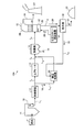
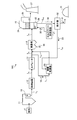
- FIG. 1 is a schematic configuration diagram of an exhaust gas treatment system according to a first embodiment.
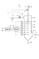
- FIG. 2 is a schematic view of a spray dryer for dehydrated filtrate from desulfurized wastewater according to the first embodiment.
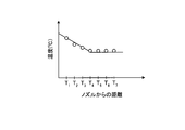
- FIG. 3A is a relationship diagram between the distance from the nozzle to the thermometers (T 1 to T 7 ) provided at seven locations in the spray drying apparatus main body and the measured temperature.
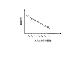
- FIG. 3-2 is a relationship diagram between the distance from the nozzle to the thermometers (T 1 to T 7 ) provided at seven locations in the spray drying apparatus main body and the measured temperature.
- FIG. 4 is a schematic configuration diagram of an exhaust gas treatment system according to a second embodiment.
- FIG. 5 is a schematic configuration diagram of an exhaust gas treatment system according to a third embodiment.
- FIG. 1 is a schematic configuration diagram of an exhaust gas treatment system according to a first embodiment.
- An exhaust gas treatment system 10A exemplified in FIG. 1 includes nitrogen oxide (NO x ), sulfur from exhaust gas 18 from a boiler 11 such as a coal fired boiler using coal as a fuel or a heavy oil fired boiler using heavy oil as a fuel. This is a device for removing harmful substances such as oxide (SO x ) and mercury (Hg).
- NO x nitrogen oxide
- SO x oxide
- Hg mercury
- the exhaust gas treatment system 10A includes a boiler 11 that burns fuel F, an air heater 13 that recovers heat of the exhaust gas 18 from the boiler 11, a dust collector 14 that removes soot and dust in the exhaust gas 18 after heat recovery, A desulfurization device 15 that removes sulfur oxides contained in the exhaust gas 18 with a lime slurry 20 that is an absorbing solution, a dehydrator 32 that removes gypsum 31 from a desulfurization drainage 30 discharged from the desulfurization device 15, and the dehydrator
- the spray dryer 50 provided with the spraying means for spraying the dehydrated filtrate 33 from 32 and the exhaust gas introduction line L 11 for introducing a part of the exhaust gas 18 into the spray dryer 50 are provided.
- Denitration device 12 is a device for removing nitrogen oxides in the exhaust gas 18 supplied from the boiler 11 through the gas supply line L 1, and has inside thereof denitration catalyst layer (not shown).
- a reducing agent injector (not shown) is disposed upstream of the denitration catalyst layer, and the reducing agent is injected into the exhaust gas 18 from the reducing agent injector.
- ammonia, urea, ammonium chloride or the like is used as the reducing agent.
- the nitrogen oxides in the exhaust gas 18 introduced into the denitration device 12 come into contact with the denitration catalyst layer, so that the nitrogen oxides in the exhaust gas 18 are decomposed and removed into nitrogen gas (N 2 ) and water (H 2 O). Is done.
- the mercury in the exhaust gas 18 increases the proportion of divalent mercury chloride soluble in water as the chlorine (Cl) content in the exhaust gas increases, and mercury is easily collected by the desulfurization apparatus 15 described later.
- the denitration device 12 is not essential, and when the nitrogen oxide concentration or mercury concentration in the exhaust gas 18 from the boiler 11 is very small, or when these substances are not contained in the exhaust gas 18, denitration is performed. It is also possible to omit the device 12.
- the air heater 13 is a heat exchanger that recovers heat in the exhaust gas 18 supplied through the exhaust gas supply line L 2 after nitrogen oxides are removed by the denitration device 12. Since the temperature of the exhaust gas 18 that has passed through the denitration device 12 is as high as about 350 ° C. to 400 ° C., heat exchange is performed between the high temperature exhaust gas 18 and normal temperature combustion air by the air heater 13. The combustion air that has reached a high temperature due to heat exchange is supplied to the boiler 11. On the other hand, the exhaust gas 18 subjected to heat exchange with room temperature combustion air is cooled to about 150 ° C.
- the dust collector 14 removes soot and dust in the exhaust gas 18 supplied via the gas supply line L 3 after heat recovery.
- Examples of the dust collector 14 include an inertial dust collector, a centrifugal dust collector, a filtration dust collector, an electric dust collector, and a cleaning dust collector, but are not particularly limited.
- the desulfurization device 15 is a device that removes sulfur oxide in the exhaust gas 18 supplied via the gas supply line L 4 in a wet manner after the dust is removed.
- lime slurry 20 an aqueous solution in which limestone powder is dissolved in water
- the temperature in the apparatus is adjusted to about 30 to 80 ° C.
- the lime slurry 20 is supplied from the lime slurry supply device 21 to the tower bottom 22 of the desulfurization device 15.
- the lime slurry 20 supplied to the tower bottom 22 of the desulfurization apparatus 15 is sent to a plurality of nozzles 23 in the desulfurization apparatus 15 via an absorption liquid supply line (not shown), and ejected from the nozzle 23 toward the tower top 24 side. Is done.
- an absorption liquid supply line not shown
- sulfur oxide and mercury chloride in the exhaust gas 18 are absorbed by the lime slurry 20, It is separated from the exhaust gas 18 and removed.
- the exhaust gas 18 purified by the lime slurry 20 is discharged from the tower top 24 side of the desulfurization device 15 as the purified gas 26 and is discharged out of the system from the chimney 27.
- the sulfur oxide SO x in the exhaust gas 18 causes a reaction represented by the lime slurry 20 and the following formula (1).
- the lime slurry 20 that has absorbed SO x in the exhaust gas 18 is oxidized by air (not shown) supplied to the tower bottom 22 of the desulfurization device 15, and the reaction represented by the following equation (2) with air.
- air (not shown) supplied to the tower bottom 22 of the desulfurization device 15, and the reaction represented by the following equation (2) with air.
- SO x in the exhaust gas 18 is captured in the form of gypsum CaSO 4 .2H 2 O in the desulfurization apparatus 15.
- the lime slurry 20 is obtained by pumping the liquid stored in the tower bottom 22 of the desulfurization device 15, and the lime slurry 20 to be pumped is accompanied by the operation of the desulfurization device 15.
- Gypsum CaSO 4 .2H 2 O is mixed according to the reaction formulas (1) and (2).
- this lime-gypsum slurry (lime slurry mixed with gypsum) to be pumped is called an absorbent.
- Absorbing solution used for desulfurization (limestone gypsum slurry) is discharged from the bottom portion 22 of the desulfurization apparatus 15 to the outside as a desulfurization effluent 30 is sent to the dehydrator 32 through the drain line L 20 to be described later, wherein the dehydration treatment Is done.
- the desulfurization effluent 30 contains heavy metals such as mercury and halogen ions such as Cl ⁇ , Br ⁇ , I ⁇ and F ⁇ .
- the dehydrator 32 separates the solid component containing the gypsum 31 in the desulfurization waste water 30 and the dehydrated filtrate 33 of the liquid component.
- the dehydrator 32 for example, a belt filter, a centrifugal separator, a decanter type centrifugal sedimentator or the like is used.
- the gypsum 31 is separated by a dehydrator 32.
- mercury chloride in the desulfurization waste water 30 is separated from the liquid together with the gypsum 31 in a state of being adsorbed on the gypsum 31.
- the separated gypsum 31 is discharged outside the system (hereinafter referred to as “outside of the system”).
- a separated liquid dehydrating filtrate 33 is sent to a spray dryer 50 via a dehydration line L 21.
- the dehydrated filtrate 33 may be temporarily stored in a drain tank (not shown).
- the spray dryer 50 includes gas introduction means for introducing a part of exhaust gas through an exhaust gas introduction line L 11 branched from the exhaust gas supply line L 2, and spray means for spraying or spraying the dehydrated filtrate 33. Yes. Then, the dehydrated filtrate 33 sprayed by the heat of the introduced exhaust gas 18 is evaporated and dried.
- Reference numeral L 12 is a gas supply line for feeding the exhaust gas that has contributed to the drying in a spray dryer to the gas supply line L 3.
- the dehydrated filtrate 33 from which the gypsum 31 has been removed from the desulfurization waste water is spray-dried, clogging by the spraying means can be prevented. That is, since the desulfurization wastewater itself is not sprayed, the amount of dry particles generated as the desulfurization wastewater evaporates can be greatly reduced. As a result, clogging due to adhesion of dry particles can be reduced. Further, by dehydrating the desulfurization waste water 30, mercury chloride is separated and removed together with the gypsum 31, so that it is possible to prevent the mercury concentration in the exhaust gas 18 from increasing when spraying the waste water.
- part of the exhaust gas flowing into the air heater 13 is branched from the exhaust gas supply line L 2 via the exhaust gas introduction line L 11 , so that the temperature of the exhaust gas is high (350 to 400 ° C.) and dehydration.
- the filtrate 33 can be efficiently spray-dried.
- FIG. 2 is a schematic view of a spray dryer for dehydrated filtrate from desulfurization effluent according to the present embodiment.
- the spray drying apparatus of the present embodiment is provided in the spray drying apparatus main body 51, the spray nozzle 52 for spraying the dehydrated filtrate 33 from the desulfurization waste water, and the spray drying apparatus main body 51.
- thermometer T 1 ⁇ T 7 for measuring the internal temperature
- the measurement results of the thermometers T 1 ⁇ T 7 determines the quality of the spray-drying condition of the dehydration filtrate 33
- control unit 55 that adjusts the exhaust gas 18 or the dehydrated filtrate 33 when it is determined that the spray drying is defective as a result of the determination by the determination unit 54.
- Reference numeral 56 denotes a separated solid substance
- L 22 denotes a supply line for supplying the dehydrated filtrate 33 to the dust collection ash 16.
- thermometers (T 1 to T 7 ) are provided at seven locations, but the present invention is not limited to this, and is appropriately changed according to the length of the drying region 53.
- the temperature measurement is installed on the vertical axis portion of the apparatus main body, the present invention is not limited to this, and may be installed anywhere as long as it can be installed at a position where the evaporation state can be confirmed.
- FIGS. 3A and 3B are graphs showing the relationship between the measured temperature and the distance from the nozzle to the thermometers (T 1 to T 7 ) provided at seven locations in the spray drying apparatus main body.
- T 1 to T 7 thermometers
- control means 55 adjusts the exhaust gas 18 or the dehydrated filtrate 33.
- adjustment of the dehydrated filtrate 33 is performed by operating the adjustment valve V 1 to increase or decrease the supply amount of the dehydrated filtrate 33 or increase or decrease the supply amount of atomized air supplied to the spray nozzle 52. Make adjustments. Further, a buffer tank for storing a predetermined amount of the dehydrated filtrate 33 may be provided for adjustment.
- the flow rate information (* 1) obtained by measuring the flow rate of the dehydrated filtrate 33 (not shown) and the flow rate information (* 2) obtained by measuring the flow rate of the exhaust gas 18 are input to the control means 55.
- the opening degree is adjusted or the pump flow rate (not shown) is adjusted.
- the exhaust gas 18 is adjusted by controlling the amount of exhaust gas introduced.
- the introduction amount is adjusted by controlling the opening degree of the valve V 2 or the damper by adjusting the pressure loss with the exhaust gas introduction line L 11 .
- an exhaust gas introduction line L 11 as a plurality of sequences, a spray dryer 50 installed above two, may be adjusted the supply amount of the exhaust gas.
- the spray-dried state of the dehydrated filtrate is monitored for the temperature state in the drying region. Therefore, the spray-dried state can be stably maintained and desulfurization drainage can be eliminated.
- FIG. 4 is a schematic configuration diagram of an exhaust gas treatment system according to a second embodiment.
- An exhaust gas treatment system 10B illustrated in FIG. 4 is a solid-liquid separation that removes suspended solids (SS) or suspended substances in the desulfurized filtrate 33 in the exhaust gas treatment system 10A according to the first embodiment.
- the device 41 is obtained by interposing a dewatering line L 21. Examples of the solid-liquid separation device 41 include a liquid cyclone, a belt filter, a classifier, and a membrane separation device.
- This solid-liquid separation device 41 removes suspended substances (SS) in the dehydrated filtrate 33, and the SS concentration in the separation liquid 42 is 1% by weight or less, more preferably 0.1 to 0.5% by weight.
- concentration reduces and clogging of the nozzle, piping, etc. in the spray dryer 50 can further be suppressed.
- the SS concentration to 1% by weight or less, more preferably 0.1 to 0.5% by weight, it is possible to prevent the spray-dried material from adhering to the tip of the spray nozzle during spray-drying or the growth of dust. , The occurrence of spray failure is suppressed.
- the separation residue 43 separated by the solid-liquid separation device may be joined to the dust collection ash 16 so that the dehydrated filtrate 33 contains water.
- the dust collection ash 16 and the residue may be sprayed with the dehydrated filtrate 33 in different places.
- the introduction of the exhaust gas 18 may be performed by introducing the exhaust gas 18 into the spray dryer 50 due to the difference in pressure loss between the exhaust gas supply line L 2 and the exhaust gas introduction line L 11 , or by introducing an induction fan or the like as necessary.
- the exhaust gas 18 is introduced.
- FIG. 5 is a schematic configuration diagram of an exhaust gas treatment system according to a third embodiment.
Landscapes
- Engineering & Computer Science (AREA)
- Chemical & Material Sciences (AREA)
- Environmental & Geological Engineering (AREA)
- Chemical Kinetics & Catalysis (AREA)
- Oil, Petroleum & Natural Gas (AREA)
- Biomedical Technology (AREA)
- Analytical Chemistry (AREA)
- General Chemical & Material Sciences (AREA)
- Health & Medical Sciences (AREA)
- Life Sciences & Earth Sciences (AREA)
- Water Supply & Treatment (AREA)
- Hydrology & Water Resources (AREA)
- Organic Chemistry (AREA)
- Mechanical Engineering (AREA)
- General Engineering & Computer Science (AREA)
- Microbiology (AREA)
- Treating Waste Gases (AREA)
- Heat Treatment Of Water, Waste Water Or Sewage (AREA)
- Vaporization, Distillation, Condensation, Sublimation, And Cold Traps (AREA)
Abstract
噴霧乾燥装置本体51内に、脱硫排水からの脱水濾液33を噴霧する噴霧ノズル52と、噴霧乾燥装置本体51に設けられ、噴霧液33aを乾燥する排ガス18を導入する導入口51aと、噴霧乾燥装置本体51内に設けられ、排ガス18により脱水濾液33を乾燥する乾燥領域53と、乾燥に寄与した排ガス18を排出する排出口51bと、乾燥領域内に複数設けられ、内部の温度を計測する温度計T1~T7と、温度計の計測結果により、脱水濾液33の噴霧・乾燥状態の良否の判断を行う判定手段54と、判定手段54の判断の結果、噴霧乾燥不良であると判断した場合に、排ガス又は脱水濾液の調整を行う制御手段55とを具備する。
Description
本発明は、ボイラから排出される排ガスを処理する排ガス処理の際に発生する脱硫排水からの脱水濾液の噴霧乾燥装置、排ガス処理システム及び方法に関する。
従来、火力発電設備等に設置されるボイラから排出される排ガスを処理するための排ガス処理システムが知られている。排ガス処理システムは、ボイラからの排ガスから窒素酸化物を除去する脱硝装置と、脱硝装置を通過した排ガスの熱を回収するエアヒータと、熱回収後の排ガス中の煤塵を除去する集塵機と、除塵後の排ガス中の硫黄酸化物を除去するための脱硫装置とを備えている。脱硫装置としては、石灰吸収液等を排ガスと気液接触させて排ガス中の硫黄酸化物を除去する湿式の脱硫装置が一般的に用いられる。
湿式の脱硫装置から排出される排水(以下、「脱硫排水」という。)には、塩素イオン、アンモニウムイオン等のイオンや水銀など様々な種類の有害物質が多量に含まれる。このため、脱硫排水をシステム外部に放流する前に脱硫排水からこれらの有害物質を除去する必要があるが、脱硫排水中に含まれるこれら多種類の有害物質の除去処理は複雑であり、処理コストが高いという問題がある。そこで、脱硫排水の処理コストを節減すべく、脱硫排水をシステム外部に放出することなくシステム内で再利用する方法が提案されている。例えば、特許文献1及び2には、脱硝装置、エアヒータ、集塵機、脱硫装置とが接続される主ラインの煙道から分岐して、脱硫排水を噴霧してガス化する設備を別途設置し、主ラインの煙道から排ガスの一部をこの設備内に導入し、設備内の排ガス中に脱硫排水を噴霧して蒸発させることにより有害物質を析出させた後、このガスを主ラインの煙道に戻すように構成された排ガス処理装置が開示されている(特許文献1及び2)。
しかしながら、特許文献1及び2の排ガス処理装置では、煙道から排ガスを一部分岐して、脱硫装置からの脱硫排水(又は排液)を噴霧してガス化する設備を設けて、脱硫排水を蒸発させているが、脱硫装置からの脱硫排水は、固形分が含有されているために、噴霧乾燥を良好に行うことができない、という問題がある。
さらに、近年、内陸部等における水資源に対する環境配慮のために、排ガス処理設備における無排水化が切望されており、安定して操業することができる無排水化を図る排ガス処理設備の出現が切望されている。
この無排水化を実施する設備として、脱硫排水を乾燥する噴霧乾燥機を用いることができるが、脱硫排水を噴霧乾燥する場合には、以下のような問題がある。
1)熱量バランスの乱れによる問題
噴霧液を蒸発させるには、噴霧液と温風との熱移動により乾燥が促進されるが、温風に対して噴霧液が過剰の場合には、蒸発不良が発生する。
2)灰付着による噴霧液の液滴径の粗大化による問題
噴霧ノズル先端部に灰が付着すると、ノズルから発生する噴霧液滴径が変化し、一般的には粗大化する。この粗大化した液滴は、温風と熱交換する比表面積が小さく、熱交換が遅いため、蒸発遅れが発生する。
1)熱量バランスの乱れによる問題
噴霧液を蒸発させるには、噴霧液と温風との熱移動により乾燥が促進されるが、温風に対して噴霧液が過剰の場合には、蒸発不良が発生する。
2)灰付着による噴霧液の液滴径の粗大化による問題
噴霧ノズル先端部に灰が付着すると、ノズルから発生する噴霧液滴径が変化し、一般的には粗大化する。この粗大化した液滴は、温風と熱交換する比表面積が小さく、熱交換が遅いため、蒸発遅れが発生する。
本発明は、前記問題に鑑み、安定して操業することができる無排水化を図る脱硫排水からの脱水濾液の噴霧乾燥装置、排ガス処理システム及び排ガス処理方法を提供することを課題とする。
上述した課題を解決するための本発明の第1の発明は、噴霧乾燥装置本体内に、脱硫排水からの脱水濾液を噴霧する噴霧ノズルと、噴霧乾燥装置本体に設けられ、噴霧液を乾燥する排ガスを導入する導入口と、噴霧乾燥装置本体内に設けられ、排ガスにより脱水濾液を乾燥する乾燥領域と、乾燥に寄与した排ガスを排出する排出口と、前記乾燥領域内に複数設けられ、内部の温度を計測する温度計と、前記温度計の計測結果により、脱水濾液の噴霧・乾燥状態の良否の判断を行う判定手段と、前記判定手段の判断の結果、噴霧乾燥不良であると判断した場合に、排ガス又は脱水濾液の調整を行う制御手段とを具備することを特徴とする脱硫排水からの脱水濾液の噴霧乾燥装置にある。
第2の発明は、第1の発明において、脱水濾液の調整は、脱水濾液の供給量の増減又はアトマイズエアの供給量の増減により行うことを特徴とする脱硫排水からの脱水濾液の噴霧乾燥装置にある。
第3の発明は、第1の発明において、排ガスの調整は、排ガスの導入量の制御により行うことを特徴とする脱硫排水からの脱水濾液の噴霧乾燥装置にある。
第4の発明は、第1乃至3のいずれか一つの発明において、噴霧乾燥不良は、温度減少度合いにより判断することを特徴とする脱硫排水からの脱水濾液の噴霧乾燥装置にある。
第5の発明は、燃料を燃焼させるボイラと、前記ボイラからの排ガスの熱を回収するエアヒータと、熱回収後の排ガス中の煤塵を除去する集塵機と、除塵後の排ガス中に含まれる硫黄酸化物を吸収液で除去する脱硫装置と、前記脱硫装置から排出される脱硫排水から石膏を除去する脱水機と、前記脱水機からの脱水濾液を噴霧する噴霧手段を備えた請求項1乃至4のいずれか一つの噴霧乾燥装置と、前記噴霧乾燥装置に排ガスの一部を導入する排ガス導入ラインとを具備することを特徴とする排ガス処理システムにある。
第6の発明は、第5の発明において、前記脱水機からの脱水濾液中の浮遊物質を除去する固液分離装置を有することを特徴とする排ガス処理システムにある。
第7の発明は、燃料を燃焼させるボイラからの排ガスの熱をエアヒータにより回収した後、脱硫装置において、熱回収後の排ガス中に含まれる硫黄酸化物を吸収液で除去する排ガス処理方法において、前記脱硫装置から排出される脱硫排水から石膏を除去した脱水濾液を、排ガスの一部により噴霧乾燥する際、脱水濾液の噴霧乾燥状態を乾燥領域における温度状態を監視しつつ行うことを特徴とする排ガス処理方法にある。
第8の発明は、第7の発明において、前記脱水濾液中の浮遊物質を除去した分離液を噴霧乾燥することを特徴とする排ガス処理方法にある。
本発明法によれば、ボイラからの排ガスを用いて、脱硫装置から分離された脱硫排水から石膏を除いた脱水濾液を用いて、噴霧乾燥機で噴霧する際、噴霧乾燥状態を把握して、噴霧不良が有る場合には除去することで、安定して噴霧することができる。これにより、脱硫装置からの脱硫排水の無排水化を実現することが可能となる。
以下、この発明につき図面を参照しつつ詳細に説明する。なお、この実施例により本発明が限定されるものではなく、また、実施例が複数ある場合には、各実施例を組み合わせて構成するものも含むものである。また、下記実施例における構成要素には、当業者が容易に想定できるもの、あるいは実質的に同一のものが含まれる。
図1は、実施例1に係る排ガス処理システムの概略構成図である。図1に例示される排ガス処理システム10Aは、石炭を燃料として使用する石炭焚きボイラや重油を燃料として使用する重油焚きボイラ等のボイラ11からの排ガス18から、窒素酸化物(NOx)、硫黄酸化物(SOx)、水銀(Hg)等の有害物質を除去する装置である。
排ガス処理システム10Aは、燃料Fを燃焼させるボイラ11と、前記ボイラ11からの排ガス18の熱を回収するエアヒータ13と、熱回収後の排ガス18中の煤塵を除去する集塵機14と、除塵後の排ガス18中に含まれる硫黄酸化物を吸収液である石灰スラリー20で除去する脱硫装置15と、前記脱硫装置15から排出される脱硫排水30から石膏31を除去する脱水機32と、前記脱水機32からの脱水濾液33を噴霧する噴霧手段を備えた噴霧乾燥機50と、前記噴霧乾燥機50に排ガス18の一部を導入する排ガス導入ラインL11とを具備するものである。これにより、石膏を除去した脱水濾液33を用いて噴霧乾燥機50で噴霧乾燥するので、安定した噴霧を行うことを可能としている。
これにより、噴霧乾燥機での目詰まりが発生せず、脱硫排水の水分の無排水化を安定して実施することができる。
これにより、噴霧乾燥機での目詰まりが発生せず、脱硫排水の水分の無排水化を安定して実施することができる。
脱硝装置12は、ボイラ11からガス供給ラインL1を介して供給される排ガス18中の窒素酸化物を除去する装置であり、その内部に脱硝触媒層(図示せず)を有している。脱硝触媒層の前流には還元剤注入器(図示せず)が配置され、この還元剤注入器から排ガス18に還元剤が注入される。ここで還元剤としては、例えばアンモニア、尿素、塩化アンモニウムなどが用いられる。脱硝装置12に導入された排ガス18中の窒素酸化物は、脱硝触媒層と接触することにより、排ガス18中の窒素酸化物が窒素ガス(N2)と水(H2O)に分解・除去される。また排ガス18中の水銀は、排ガス中の塩素(Cl)分が多くなると、水に可溶な2価の塩化水銀の割合が多くなり、後述する脱硫装置15で水銀が捕集しやすくなる。
なお、上記の脱硝装置12は必須のものではなく、ボイラ11からの排ガス18中の窒素酸化物濃度や水銀濃度が微量、あるいは、排ガス18中にこれらの物質が含まれない場合には、脱硝装置12を省略することも可能である。
エアヒータ13は、脱硝装置12で窒素酸化物が除去された後、排ガス供給ラインL2を介して供給される排ガス18中の熱を回収する熱交換器である。脱硝装置12を通過した排ガス18の温度は350℃~400℃程度と高温であるため、エアヒータ13により高温の排ガス18と常温の燃焼用空気との間で熱交換を行う。熱交換により高温となった燃焼用空気は、ボイラ11に供給される。一方、常温の燃焼用空気との熱交換を行った排ガス18は150℃程度まで冷却される。
集塵機14は、熱回収後、ガス供給ラインL3を介して供給される排ガス18中の煤塵を除去するものである。集塵機14としては慣性力集塵機、遠心力集塵機、濾過式集塵機、電気集塵機、洗浄集塵機等が挙げられるが、特に限定されない。
脱硫装置15は、煤塵が除去された後、ガス供給ラインL4を介して供給される排ガス18中の硫黄酸化物を湿式で除去する装置である。この脱硫装置15では、アルカリ吸収液として石灰スラリー20(水に石灰石粉末を溶解させた水溶液)が用いられ、装置内の温度は30~80℃程度に調節されている。石灰スラリー20は、石灰スラリー供給装置21から脱硫装置15の塔底部22に供給される。脱硫装置15の塔底部22に供給された石灰スラリー20は、図示しない吸収液送給ラインを介して脱硫装置15内の複数のノズル23に送られ、ノズル23から塔頂部24側に向かって噴出される。脱硫装置15の塔底部22側から上昇してくる排ガス18がノズル23から噴出する石灰スラリー20と気液接触することにより、排ガス18中の硫黄酸化物及び塩化水銀が石灰スラリー20により吸収され、排ガス18から分離、除去される。石灰スラリー20により浄化された排ガス18は、浄化ガス26として脱硫装置15の塔頂部24側より排出され、煙突27から系外に排出される。
脱硫装置15の内部において、排ガス18中の硫黄酸化物SOxは石灰スラリー20と下記式(1)で表される反応を生じる。
CaCO3+SO2+0.5H2O → CaSO3・0.5H2O +CO2・・・(1)
CaCO3+SO2+0.5H2O → CaSO3・0.5H2O +CO2・・・(1)
さらに、排ガス18中のSOxを吸収した石灰スラリー20は、脱硫装置15の塔底部22に供給される空気(図示せず)により酸化処理され、空気と下記式(2)で表される反応を生じる。
CaSO3・0.5H2O+0.5O2+1.5H2O → CaSO4・2H2O・・・(2)
このようにして、排ガス18中のSOxは、脱硫装置15において石膏CaSO4・2H2Oの形で捕獲される。
CaSO3・0.5H2O+0.5O2+1.5H2O → CaSO4・2H2O・・・(2)
このようにして、排ガス18中のSOxは、脱硫装置15において石膏CaSO4・2H2Oの形で捕獲される。
また、上記のように、石灰スラリー20は、脱硫装置15の塔底部22に貯留した液を揚水したものが用いられるが、この揚水される石灰スラリー20には、脱硫装置15の稼働に伴い、反応式(1)、(2)により石膏CaSO4・2H2Oが混合される。以下では、この揚水される石灰石膏スラリー(石膏が混合された石灰スラリー)を吸収液とよぶ。
脱硫に用いた吸収液(石灰石膏スラリー)は、脱硫排水30として脱硫装置15の塔底部22から外部に排出され、後述する排水ラインL20を介して脱水機32に送られ、ここで脱水処理される。この脱硫排水30には、石膏の他、水銀等の重金属やCl-、Br-、I-、F-等のハロゲンイオンが含まれている。
脱水機32は、脱硫排水30中の石膏31を含む固体分と液体分の脱水濾液33とを分離するものである。脱水機32としては、例えばベルトフィルタ、遠心分離機、デカンタ型遠心沈降機等が用いられる。脱硫装置15から排出された脱硫排水30は、脱水機32により石膏31が分離される。その際、脱硫排水30中の塩化水銀は石膏31に吸着された状態で石膏31とともに液体と分離される。分離した石膏31は、システム外部(以下、「系外」という)に排出される。
一方、分離液である脱水濾液33は脱水ラインL21を介して噴霧乾燥機50に送られる。なお、脱水濾液33は一時的に排水タンク(図示せず)に貯留するようにしてもよい。
一方、分離液である脱水濾液33は脱水ラインL21を介して噴霧乾燥機50に送られる。なお、脱水濾液33は一時的に排水タンク(図示せず)に貯留するようにしてもよい。
噴霧乾燥機50は、排ガス供給ラインL2から分岐した排ガス導入ラインL11を介して一部の排ガスが導入されるガス導入手段と、脱水濾液33を散布又は噴霧する噴霧手段とを具備している。そして、導入される排ガス18の熱により散布された脱水濾液33を蒸発乾燥させている。なお、符号L12は噴霧乾燥機で乾燥に寄与した排ガスをガス供給ラインL3に送給する排ガス供給ラインである。
本発明では、脱硫排水から石膏31を除去した脱水濾液33を噴霧乾燥しているので、噴霧手段での目詰まりを防止することができる。
すなわち、脱硫排水そのものを噴霧するのではないので、脱硫排水が蒸発するのに伴い発生する乾燥粒子の量を大幅に低減させることができる。その結果、乾燥粒子の付着に起因する目詰まりを低減させることができる。また、脱硫排水30を脱水処理することにより、石膏31とともに塩化水銀も分離・除去されるため、排水噴霧時に排ガス18中の水銀濃度が増加するのを防止することができる。
すなわち、脱硫排水そのものを噴霧するのではないので、脱硫排水が蒸発するのに伴い発生する乾燥粒子の量を大幅に低減させることができる。その結果、乾燥粒子の付着に起因する目詰まりを低減させることができる。また、脱硫排水30を脱水処理することにより、石膏31とともに塩化水銀も分離・除去されるため、排水噴霧時に排ガス18中の水銀濃度が増加するのを防止することができる。
また、本実施例では、エアヒータ13へ流入する排ガスの一部を排ガス供給ラインL2から排ガス導入ラインL11を介して分岐しているので、排ガスの温度が高く(350~400℃)、脱水濾液33の噴霧乾燥を効率よく行うことができる。
図2は、本実施例に係る脱硫排水からの脱水濾液の噴霧乾燥機の概略図である。
図2に示すように、本実施例の噴霧乾燥装置は、噴霧乾燥装置本体51内に、脱硫排水からの脱水濾液33を噴霧する噴霧ノズル52と、噴霧乾燥装置本体51に設けられ、噴霧液33aを乾燥する排ガス18を導入する導入口51aと、噴霧乾燥装置本体51内に設けられ、排ガス18により脱水濾液33を乾燥する乾燥領域53と、乾燥に寄与した排ガス18を排出する排出口51bと、乾燥領域53内に複数設けられ、内部の温度を計測する温度計T1~T7と、温度計T1~T7の計測結果により、脱水濾液33の噴霧・乾燥状態の良否の判断を行う判定手段54と、判定手段54の判断の結果、噴霧乾燥不良であると判断した場合に、排ガス18又は脱水濾液33の調整を行う制御手段55とを具備するものである。なお、符号56は分離された固形物、L22は脱水濾液33を集塵灰16に供給する供給ラインを図示する。
図2に示すように、本実施例の噴霧乾燥装置は、噴霧乾燥装置本体51内に、脱硫排水からの脱水濾液33を噴霧する噴霧ノズル52と、噴霧乾燥装置本体51に設けられ、噴霧液33aを乾燥する排ガス18を導入する導入口51aと、噴霧乾燥装置本体51内に設けられ、排ガス18により脱水濾液33を乾燥する乾燥領域53と、乾燥に寄与した排ガス18を排出する排出口51bと、乾燥領域53内に複数設けられ、内部の温度を計測する温度計T1~T7と、温度計T1~T7の計測結果により、脱水濾液33の噴霧・乾燥状態の良否の判断を行う判定手段54と、判定手段54の判断の結果、噴霧乾燥不良であると判断した場合に、排ガス18又は脱水濾液33の調整を行う制御手段55とを具備するものである。なお、符号56は分離された固形物、L22は脱水濾液33を集塵灰16に供給する供給ラインを図示する。
本実施例では、7箇所に温度計(T1~T7)を設けているが、本発明はこれに限定されず、乾燥領域53の長さに応じて適宜変更するようにしている。
なお、温度計測は装置本体の鉛直軸線部分に設置しているが、本発明はこれに限定されず、蒸発状態を確認する位置に設置することができれば、いずれに設置してもよい。
なお、温度計測は装置本体の鉛直軸線部分に設置しているが、本発明はこれに限定されず、蒸発状態を確認する位置に設置することができれば、いずれに設置してもよい。
図3-1及び図3-2は、噴霧乾燥装置本体内の7箇所に設けた温度計(T1~T7)に対するノズルからの距離と、計測温度との関係図である。
ここで、液体の蒸発過程では、噴霧液33aの液滴の温度上昇や蒸発に対して熱が必要となる。この場合、排ガス18の熱が液滴の温度上昇や蒸発に使用されるので、排ガス18の温度が下がることとなる。この温度の低下を検知することで乾燥の良否を判断するようにしている。
図3-1は、乾燥が良好な場合の関係図であり、図3-2は、乾燥が不良の場合の関係図である。
図3-1では、温度減少がT4付近から止まり、温度が一定となっている。これは、噴霧液33aの液滴が無いことに起因する。
これに対して、図3-2では、温度減少がT7まで断続的に低下している。これは、噴霧液33aの液滴が多量に残存していることに起因する。
ここで、液体の蒸発過程では、噴霧液33aの液滴の温度上昇や蒸発に対して熱が必要となる。この場合、排ガス18の熱が液滴の温度上昇や蒸発に使用されるので、排ガス18の温度が下がることとなる。この温度の低下を検知することで乾燥の良否を判断するようにしている。
図3-1は、乾燥が良好な場合の関係図であり、図3-2は、乾燥が不良の場合の関係図である。
図3-1では、温度減少がT4付近から止まり、温度が一定となっている。これは、噴霧液33aの液滴が無いことに起因する。
これに対して、図3-2では、温度減少がT7まで断続的に低下している。これは、噴霧液33aの液滴が多量に残存していることに起因する。
この結果を判定手段54で判断する。
この判定手段54での判断の結果、乾燥良好である場合には、そのまま脱水濾液33の噴霧乾燥を継続する。
この判定手段54での判断の結果、乾燥良好である場合には、そのまま脱水濾液33の噴霧乾燥を継続する。
これに対し、判断手段54での判断の結果、乾燥不良であると判断した場合には、排ガス18又は脱水濾液33の調整を制御手段55により行うようにしている。
具体的には、脱水濾液33の調整は、調整バルブV1を操作して脱水濾液33の供給量の増減又は噴霧ノズル52に供給するアトマイズエアの供給量の増減により、噴霧液の液滴径の調整をする。
また、脱水濾液33を所定量備蓄するバッファタンクを設け、調整を行うようにしてもよい。
また、脱水濾液33を所定量備蓄するバッファタンクを設け、調整を行うようにしてもよい。
このため、制御手段55には図示しない脱水濾液33の流量を計測した流量情報(※1)、排ガス18の流量を計測した流量情報(※2)が入力され、この情報をもとに、バルブ開度の調整又は図示しないポンプ流量の調整を行うようにしている。
また、排ガス18の調整は、排ガスの導入量の制御により行うようにしている。
導入量の調整は、排ガス導入ラインL11との圧損調整によるバルブV2又はダンパ等の開度の制御により調整を行うようにしている。
導入量の調整は、排ガス導入ラインL11との圧損調整によるバルブV2又はダンパ等の開度の制御により調整を行うようにしている。
また、排ガス導入ラインL11を複数系列として、噴霧乾燥機50を2台以上設置し、排ガスの供給量を調整するようにしてもよい。
また、温度計測により、瞬間的な判断だけではなく、経時的に温度プロファイルを計測し乾燥良好な状態から乾燥不良の状態に過渡的に変化することを確認できた時点で、乾燥不良の要因を改善する前述した操作を行うようにしてもよい。
本実施例によれば、前記脱硫装置から排出される脱硫排水から石膏を除去した脱水濾液を、排ガスの一部により噴霧乾燥する際、脱水濾液の噴霧乾燥状態を乾燥領域における温度状態を監視しつつ行うことしているので、安定して噴霧乾燥状態を保持でき、脱硫排水の無排水化を実施することができる。
次に、実施例2に係る排ガス処理システムについて説明する。
図4は、実施例2に係る排ガス処理システムの概略構成図である。なお、上述した実施例1と同一の構成には同一の符号を付し、その説明を省略する。図4に例示される排ガス処理システム10Bは、実施例1に係る排ガス処理システム10Aにおいて、脱硫濾液33中の浮遊物質(SS:suspended solids)又は懸濁物質(suspended substance)を除去する固液分離装置41を脱水ラインL21に介装したものである。
固液分離装置41としては、例えば液体サイクロン、ベルトフィルタ、分級器、膜分離装置等を挙げることができる。
図4は、実施例2に係る排ガス処理システムの概略構成図である。なお、上述した実施例1と同一の構成には同一の符号を付し、その説明を省略する。図4に例示される排ガス処理システム10Bは、実施例1に係る排ガス処理システム10Aにおいて、脱硫濾液33中の浮遊物質(SS:suspended solids)又は懸濁物質(suspended substance)を除去する固液分離装置41を脱水ラインL21に介装したものである。
固液分離装置41としては、例えば液体サイクロン、ベルトフィルタ、分級器、膜分離装置等を挙げることができる。
この固液分離装置41は、脱水濾液33中の浮遊物質(SS)を除去し、分離液42中のSS濃度を1重量%以下、より好ましくは0.1~0.5重量%としている。
これにより、SS濃度が低減し、噴霧乾燥機50でのノズルや配管等の詰まりをさらに抑制することができる。
すなわち、SS濃度を1重量%以下、より好ましくは0.1~0.5重量%とすることで、噴霧乾燥の際の噴霧ノズル先端部での噴霧乾燥物の付着や、煤塵の付着成長により、噴霧不良となることが抑制される。この結果、閉塞による運転停止、噴霧液滴径の粗大化による必要乾燥時間の長期化に起因する乾燥不足等が解消される。また、噴霧範囲のかたよりに起因する乾燥状況の乾燥ムラ、乾燥不足等が解消される。
これにより、SS濃度が低減し、噴霧乾燥機50でのノズルや配管等の詰まりをさらに抑制することができる。
すなわち、SS濃度を1重量%以下、より好ましくは0.1~0.5重量%とすることで、噴霧乾燥の際の噴霧ノズル先端部での噴霧乾燥物の付着や、煤塵の付着成長により、噴霧不良となることが抑制される。この結果、閉塞による運転停止、噴霧液滴径の粗大化による必要乾燥時間の長期化に起因する乾燥不足等が解消される。また、噴霧範囲のかたよりに起因する乾燥状況の乾燥ムラ、乾燥不足等が解消される。
固液分離装置で分離した分離残渣43は、集塵灰16に合流させ、脱水濾液33により水分を含ませるようにしてもよい。
なお、集塵灰16単独で別途利用するような場合には、集塵灰16と残渣とを別々の場所において脱水濾液33の噴霧処理を行うようにすればよい。
なお、集塵灰16単独で別途利用するような場合には、集塵灰16と残渣とを別々の場所において脱水濾液33の噴霧処理を行うようにすればよい。
また、排ガス導入ラインL11に設けた噴霧乾燥機50の前段側又は後段側のいずれか一方又は両方に小型の集塵機を設け、排ガス中の煤塵を排ガス導入ラインL11にて除去するようにしてもよい。
なお、排ガス18の導入は、排ガス供給ラインL2と排ガス導入ラインL11との圧力損失の相違により、排ガス18を噴霧乾燥機50内へ導入するようにしたり、必要に応じて誘引ファン等を用いて排ガス18を導入したりしている。
次に、実施例3に係る排ガス処理システムについて説明する。なお、上述した実施例1と同一の構成には同一の符号を付し、その説明を省略する。
図5は、実施例3に係る排ガス処理システムの概略構成図である。本実施例に係る排ガス処理システム10Cでは、図5に示すように、排ガス18の分岐をエアヒータ13のガス供給ラインL3から行っており、噴霧乾燥機50で噴霧乾燥に寄与した排ガスを再び同じ箇所のガス供給ラインL3に戻している。
これにより、実施例1のようなバイパスラインを設けることが不要となる。
図5は、実施例3に係る排ガス処理システムの概略構成図である。本実施例に係る排ガス処理システム10Cでは、図5に示すように、排ガス18の分岐をエアヒータ13のガス供給ラインL3から行っており、噴霧乾燥機50で噴霧乾燥に寄与した排ガスを再び同じ箇所のガス供給ラインL3に戻している。
これにより、実施例1のようなバイパスラインを設けることが不要となる。
10A~10C 排ガス処理システム
11 ボイラ
12 脱硝装置
13 エアヒータ
14 集塵機
15 脱硫装置
16 集塵灰
18 排ガス
20 石灰スラリー
21 石灰スラリー供給装置
22 塔底部
23 ノズル
24 塔頂部
26 浄化ガス
27 煙突
30 脱硫排水
32 脱水機
33 脱水濾液
50 噴霧乾燥機
11 ボイラ
12 脱硝装置
13 エアヒータ
14 集塵機
15 脱硫装置
16 集塵灰
18 排ガス
20 石灰スラリー
21 石灰スラリー供給装置
22 塔底部
23 ノズル
24 塔頂部
26 浄化ガス
27 煙突
30 脱硫排水
32 脱水機
33 脱水濾液
50 噴霧乾燥機
Claims (8)
- 噴霧乾燥装置本体内に、脱硫排水からの脱水濾液を噴霧する噴霧ノズルと、
噴霧乾燥装置本体に設けられ、噴霧液を乾燥する排ガスを導入する導入口と、
噴霧乾燥装置本体内に設けられ、排ガスにより脱水濾液を乾燥する乾燥領域と、
乾燥に寄与した排ガスを排出する排出口と、
前記乾燥領域内に複数設けられ、内部の温度を計測する温度計と、
前記温度計の計測結果により、脱水濾液の噴霧・乾燥状態の良否の判断を行う判定手段と、
前記判定手段の判断の結果、噴霧乾燥不良であると判断した場合に、排ガス又は脱水濾液の調整を行う制御手段とを具備することを特徴とする脱硫排水からの脱水濾液の噴霧乾燥装置。 - 請求項1において、
脱水濾液の調整は、脱水濾液の供給量の増減又はアトマイズエアの供給量の増減により行うことを特徴とする脱硫排水からの脱水濾液の噴霧乾燥装置。 - 請求項1において、
排ガスの調整は、排ガスの導入量の制御により行うことを特徴とする脱硫排水からの脱水濾液の噴霧乾燥装置。 - 請求項1乃至3のいずれか一つにおいて、
噴霧乾燥不良は、温度減少度合いにより判断することを特徴とする脱硫排水からの脱水濾液の噴霧乾燥装置。 - 燃料を燃焼させるボイラと、
前記ボイラからの排ガスの熱を回収するエアヒータと、
熱回収後の排ガス中の煤塵を除去する集塵機と、
除塵後の排ガス中に含まれる硫黄酸化物を吸収液で除去する脱硫装置と、
前記脱硫装置から排出される脱硫排水から石膏を除去する脱水機と、
前記脱水機からの脱水濾液を噴霧する噴霧手段を備えた請求項1乃至4のいずれか一つの噴霧乾燥装置と、
前記噴霧乾燥装置に排ガスの一部を導入する排ガス導入ラインとを具備することを特徴とする排ガス処理システム。 - 請求項5において、
前記脱水機からの脱水濾液中の浮遊物質を除去する固液分離装置を有することを特徴とする排ガス処理システム。 - 燃料を燃焼させるボイラからの排ガスの熱をエアヒータにより回収した後、
脱硫装置において、熱回収後の排ガス中に含まれる硫黄酸化物を吸収液で除去する排ガス処理方法において、
前記脱硫装置から排出される脱硫排水から石膏を除去した脱水濾液を、排ガスの一部により噴霧乾燥する際、脱水濾液の噴霧乾燥状態を乾燥領域における温度状態を監視しつつ行うことを特徴とする排ガス処理方法。 - 請求項7において、
前記脱水濾液中の浮遊物質を除去した分離液を噴霧乾燥することを特徴とする排ガス処理方法。
Priority Applications (5)
| Application Number | Priority Date | Filing Date | Title |
|---|---|---|---|
| EP12761372.7A EP2689822B1 (en) | 2011-03-24 | 2012-03-22 | Spray-drying device for dehydrated filtrate from desulfurization wastewater, exhaust gas treatment system and method |
| PL12761372T PL2689822T3 (pl) | 2011-03-24 | 2012-03-22 | Urządzenie do suszenia rozpyłowego dla odwodnionego filtratu ze ścieków z odsiarczania, układ i sposób oczyszczania gazów spalinowych |
| KR1020137013266A KR101475170B1 (ko) | 2011-03-24 | 2012-03-22 | 탈황 배수로부터의 탈수 여과액의 분무 건조 장치, 배기 가스 처리 시스템 및 방법 |
| CN201280003708.1A CN103221115B (zh) | 2011-03-24 | 2012-03-22 | 来自脱硫排水的脱水滤液的喷雾干燥装置、废气处理系统及方法 |
| US13/988,644 US9555341B2 (en) | 2011-03-24 | 2012-03-22 | Spray-drying device for dehydrated filtrate from desulfurization wastewater, air pollution control system and flue gas treatment method |
Applications Claiming Priority (2)
| Application Number | Priority Date | Filing Date | Title |
|---|---|---|---|
| JP2011066776A JP2012200657A (ja) | 2011-03-24 | 2011-03-24 | 脱硫排液からの脱水濾液の噴霧乾燥装置、排ガス処理システム及び方法 |
| JP2011-066776 | 2011-03-24 |
Publications (1)
| Publication Number | Publication Date |
|---|---|
| WO2012128330A1 true WO2012128330A1 (ja) | 2012-09-27 |
Family
ID=46879471
Family Applications (1)
| Application Number | Title | Priority Date | Filing Date |
|---|---|---|---|
| PCT/JP2012/057389 Ceased WO2012128330A1 (ja) | 2011-03-24 | 2012-03-22 | 脱硫排水からの脱水濾液の噴霧乾燥装置、排ガス処理システム及び方法 |
Country Status (7)
| Country | Link |
|---|---|
| US (1) | US9555341B2 (ja) |
| EP (1) | EP2689822B1 (ja) |
| JP (1) | JP2012200657A (ja) |
| KR (1) | KR101475170B1 (ja) |
| CN (1) | CN103221115B (ja) |
| PL (1) | PL2689822T3 (ja) |
| WO (1) | WO2012128330A1 (ja) |
Cited By (12)
| Publication number | Priority date | Publication date | Assignee | Title |
|---|---|---|---|---|
| CN106587235A (zh) * | 2017-02-09 | 2017-04-26 | 北京哈宜节能环保科技开发有限公司 | 一种全负荷梯度烟气余热蒸发废水控制系统及其控制方法 |
| CN108046499A (zh) * | 2017-12-18 | 2018-05-18 | 宁波大学 | 一种以喷淋塔为加料仓的脱硫废水干燥节能减排系统 |
| CN111439882A (zh) * | 2020-04-28 | 2020-07-24 | 大唐环境产业集团股份有限公司 | 一种利用电厂烟气余热的脱硫废水零排放系统 |
| CN112279329A (zh) * | 2020-11-23 | 2021-01-29 | 西安热工研究院有限公司 | 一种一体化脱硫废水浓缩干燥塔系统 |
| CN112607943A (zh) * | 2020-12-16 | 2021-04-06 | 中国华能集团清洁能源技术研究院有限公司 | 基于四分仓空预器的燃煤电站脱硫废水处置系统及方法 |
| CN112875785A (zh) * | 2021-01-25 | 2021-06-01 | 北京京能能源技术研究有限责任公司 | 用于燃煤锅炉湿法脱硫废水深度处理系统及方法 |
| CN113185045A (zh) * | 2020-01-14 | 2021-07-30 | 大唐环境产业集团股份有限公司 | 一种脱硫废水零排放烟道蒸发并协同脱除SO3/HCl的装置及方法 |
| CN113429047A (zh) * | 2021-06-11 | 2021-09-24 | 江苏民生重工有限公司 | 一种湿法脱硫系统及其脱硫废水处理装置 |
| CN113457419A (zh) * | 2021-07-12 | 2021-10-01 | 利晟(杭州)科技有限公司 | 一种烟气排放湿度检测系统 |
| CN115806323A (zh) * | 2022-08-19 | 2023-03-17 | 中国石油化工股份有限公司 | 一种催化裂化脱硫废水处理系统及处理方法 |
| CN118307076A (zh) * | 2024-04-12 | 2024-07-09 | 湖南山水节能科技股份有限公司 | 一种基于强混器和文丘里的脱硫废水零排放干燥系统 |
| CN118558134A (zh) * | 2024-05-08 | 2024-08-30 | 华能牙克石发电有限公司 | 一种脱硫废水排放系统 |
Families Citing this family (39)
| Publication number | Priority date | Publication date | Assignee | Title |
|---|---|---|---|---|
| JP5984712B2 (ja) * | 2013-02-25 | 2016-09-06 | 三菱日立パワーシステムズ株式会社 | 排ガス処理システム及び排ガス処理方法 |
| ES2673001T3 (es) * | 2013-07-05 | 2018-06-19 | Mitsubishi Heavy Industries, Ltd. | Sistema y método de tratamiento de agua |
| AU2014285451B2 (en) * | 2013-07-05 | 2017-04-13 | Mitsubishi Heavy Industries, Ltd. | Water treatment method, and water treatment system |
| US9724638B2 (en) | 2014-01-02 | 2017-08-08 | General Electric Technology Gmbh | Apparatus and method for evaporating waste water and reducing acid gas emissions |
| US9352274B2 (en) * | 2014-01-02 | 2016-05-31 | Alstom Technology Ltd | Apparatus and method for evaporating waste water and reducing acid gas emissions |
| CN106796027B (zh) * | 2014-05-23 | 2019-08-13 | 巴布考克及威尔考克斯公司 | 用于减少来自一个或多个装置的液体排放的系统和方法 |
| US9650269B2 (en) | 2014-11-25 | 2017-05-16 | General Electric Technology Gmbh | System and method for reducing gas emissions from wet flue gas desulfurization waste water |
| US10138139B2 (en) | 2016-02-12 | 2018-11-27 | Babcock Power Environmental Inc. | Wastewater treatment systems and methods |
| DE102016108047A1 (de) | 2016-04-29 | 2017-11-02 | Mitsubishi Hitachi Power Systems Europe Gmbh | Verfahren zum abwasserfreien Betrieb einer nach einem Nassverfahren arbeitenden Rauchgasentschwefelungsanlage eines Dampfkraftwerkes sowie ein Dampfkraftwerk |
| JP7005166B2 (ja) | 2016-04-29 | 2022-01-21 | ゼネラル エレクトリック テクノロジー ゲゼルシャフト ミット ベシュレンクテル ハフツング | 廃水を蒸発させて酸性ガス排出を減らすための装置及び方法 |
| US10350542B2 (en) | 2016-04-29 | 2019-07-16 | General Electric Company | Wet flue gas desulfurization system with zero waste water liquid discharge |
| CN106512456B (zh) * | 2016-10-14 | 2018-12-28 | 北京姚魏环保技术有限公司 | 一种脱硫废水的四段法蒸发装置及方法 |
| DK3323496T3 (da) | 2016-11-18 | 2020-12-14 | General Electric Technology Gmbh | Apparat og fremgangsmåde til reduktion af emissioner af sur gas med nul-væskeudledning af spildevand |
| CN109843714B (zh) * | 2017-03-24 | 2021-09-24 | 三菱造船株式会社 | 船舶用脱硫装置的排水系统 |
| JP2018171583A (ja) * | 2017-03-31 | 2018-11-08 | 三菱日立パワーシステムズ株式会社 | 無排水化排ガス処理システム及び無排水化排ガス処理方法 |
| CN107010687A (zh) * | 2017-04-27 | 2017-08-04 | 张玉君 | 一种脱硫废水处理装置及其控制系统和控制方法 |
| CN107082464A (zh) * | 2017-06-22 | 2017-08-22 | 聊城信源集团有限公司 | 一种脱硫废水零排放处理烟道和处理系统 |
| CN107792909B (zh) * | 2017-12-08 | 2024-03-15 | 北京尤科恩环保工程有限公司 | 一种利用烟气余热浓缩脱硫废水的浓液干燥系统 |
| CN107930359A (zh) * | 2017-12-21 | 2018-04-20 | 华北电力大学(保定) | 利用脱硫废水脱除燃煤烟气中元素态汞的装置和方法 |
| CN108059294B (zh) * | 2018-01-24 | 2023-08-08 | 福建龙净环保股份有限公司 | 用于湿法脱硫的废水处理工艺系统及方法 |
| CN108579112A (zh) * | 2018-07-17 | 2018-09-28 | 重庆市易特杰机械制造有限公司 | 节能环保式沸腾干燥机 |
| CN109173715B (zh) * | 2018-10-26 | 2024-01-26 | 浙江鸿盛新材料科技集团股份有限公司 | 脱硝除尘一体化除尘器 |
| CN109126170B (zh) * | 2018-11-06 | 2024-03-12 | 中国华能集团有限公司 | 一种烟风系统及其脱硫废水的喷雾干燥装置 |
| CN109485117A (zh) * | 2018-12-28 | 2019-03-19 | 大唐环境产业集团股份有限公司 | 一种火电厂全负荷脱硫废水烟道旁路蒸发系统和方法 |
| CN110862118A (zh) * | 2019-11-06 | 2020-03-06 | 北京铝能清新环境技术有限公司 | 一种多级处理的废水零排放系统及其方法 |
| CN110921743A (zh) * | 2019-12-13 | 2020-03-27 | 合众思(北京)环境工程有限公司 | 一种脱硫废水机械压缩蒸发浓缩分盐工艺 |
| CN111115737A (zh) * | 2020-01-08 | 2020-05-08 | 上海天晓环保工程有限公司 | 一种湿法脱硫废水干燥处理装置 |
| CN111450686B (zh) * | 2020-03-31 | 2024-03-15 | 苏州仕净科技股份有限公司 | 一种脱硫脱硝除尘一体化装置 |
| CN111620399A (zh) * | 2020-06-03 | 2020-09-04 | 浙江天地环保科技股份有限公司 | 一种基于喷雾蒸发废水处理技术的废水供给自动调节装置及方法 |
| EP4169880A4 (en) * | 2020-06-17 | 2024-01-10 | Mac Jee Tecnologia Ltda. | Method for drying red water from trinitrotoluene purification process, powder and packaged product |
| CN112390317A (zh) * | 2020-10-30 | 2021-02-23 | 山东神华山大能源环境有限公司 | 一种燃煤电厂脱硫废水零排放处理工艺和设备 |
| CN112850996B (zh) * | 2021-01-20 | 2021-12-07 | 福建省福能龙安热电有限公司 | 脱硫废弃物减量优化装置 |
| CN114275836B (zh) * | 2021-12-17 | 2023-10-27 | 中石化节能技术服务有限公司 | 一种利用烟气余热处理含盐污水的方法和装置 |
| CN114314716A (zh) * | 2021-12-23 | 2022-04-12 | 国能朗新明环保科技有限公司南京分公司 | 一种高效防粘壁脱硫废水干燥处理系统 |
| CN114225570A (zh) * | 2021-12-30 | 2022-03-25 | 云南龙镁环境科技有限公司 | 一种新型脱硫喷淋塔 |
| CN114988119A (zh) * | 2022-06-15 | 2022-09-02 | 西安西热水务环保有限公司 | 一种适用火电厂脱硫废水旁路烟气蒸发高盐份灰的气力输送系统及方法 |
| CN115872547B (zh) * | 2022-11-07 | 2025-08-08 | 内蒙古上都发电有限责任公司 | 一种脱硫废水处理方法 |
| JP2024132256A (ja) * | 2023-03-17 | 2024-09-30 | 三菱重工業株式会社 | 排水乾燥システムおよび排水乾燥システムの制御方法 |
| CN117700008A (zh) * | 2023-11-29 | 2024-03-15 | 国能朗新明南京环保科技有限公司 | 一种燃煤电厂脱硫废水零排放蒸干处理工艺 |
Citations (7)
| Publication number | Priority date | Publication date | Assignee | Title |
|---|---|---|---|---|
| JPS5262770A (en) * | 1975-11-19 | 1977-05-24 | Matsushita Electric Ind Co Ltd | Dryer |
| JPS61204633U (ja) * | 1985-06-13 | 1986-12-23 | ||
| JPS63200818A (ja) | 1987-02-16 | 1988-08-19 | Mitsubishi Heavy Ind Ltd | 湿式排ガス処理装置における排液の処理方法 |
| JPH0194920A (ja) * | 1987-10-05 | 1989-04-13 | Kansai Electric Power Co Inc:The | 排ガス処理装置における排液の処理方法 |
| JPH05212369A (ja) * | 1992-02-05 | 1993-08-24 | Babcock Hitachi Kk | スプレードライヤ装置およびこれを用いた排液処理方法 |
| JPH09313881A (ja) | 1996-05-31 | 1997-12-09 | Ishikawajima Harima Heavy Ind Co Ltd | ボイラ排煙脱硫装置の無排水化装置 |
| JP2008246406A (ja) * | 2007-03-30 | 2008-10-16 | Mhi Environment Engineering Co Ltd | 排ガス処理装置および排ガス処理方法 |
Family Cites Families (10)
| Publication number | Priority date | Publication date | Assignee | Title |
|---|---|---|---|---|
| US1782054A (en) * | 1927-09-01 | 1930-11-18 | Ind Spray Drying Corp | Method and apparatus for processing materials by means of gases |
| US2576264A (en) | 1947-08-16 | 1951-11-27 | Univ Minnesota | Spray drying apparatus |
| KR870000906B1 (ko) | 1982-09-16 | 1987-05-06 | 더 뱁콕 앤드 윌콕스 캄패니 | 과립 제조 기구용 제어장치 |
| IL105658A (en) * | 1993-05-11 | 1995-10-31 | Ultrasonic Dryer Ltd | Spray drying system |
| WO2006030398A1 (en) | 2004-09-16 | 2006-03-23 | Elsam Engineering A/S | Method of operating a flue gas cleaning plant |
| CN1325419C (zh) | 2005-12-19 | 2007-07-11 | 北京朗新明环保科技有限公司 | 烟气脱硫石膏浆液的脱水方法及装置 |
| US9192889B2 (en) * | 2007-09-13 | 2015-11-24 | The Babcock & Wilcox Company | Bottom ash injection for enhancing spray dryer absorber performance |
| JP2009166010A (ja) | 2008-01-21 | 2009-07-30 | Mitsubishi Heavy Ind Ltd | 石炭焚ボイラの排ガス処理システム及び方法 |
| KR101489918B1 (ko) * | 2009-11-24 | 2015-02-05 | 게아 프로세스 엔지니어링 아/에스 | 분무 건조기 감시 방법 및 하나 이상의 적외선 카메라를 포함하는 분무 건조기 |
| US8715402B2 (en) | 2011-03-22 | 2014-05-06 | Mitsubishi Heavy Industries, Ltd. | Air pollution control system and air pollution control method, spray drying device of dewatering filtration fluid from desulfurization discharged water, and method thereof |
-
2011
- 2011-03-24 JP JP2011066776A patent/JP2012200657A/ja not_active Withdrawn
-
2012
- 2012-03-22 PL PL12761372T patent/PL2689822T3/pl unknown
- 2012-03-22 US US13/988,644 patent/US9555341B2/en active Active
- 2012-03-22 KR KR1020137013266A patent/KR101475170B1/ko not_active Expired - Fee Related
- 2012-03-22 EP EP12761372.7A patent/EP2689822B1/en active Active
- 2012-03-22 CN CN201280003708.1A patent/CN103221115B/zh active Active
- 2012-03-22 WO PCT/JP2012/057389 patent/WO2012128330A1/ja not_active Ceased
Patent Citations (7)
| Publication number | Priority date | Publication date | Assignee | Title |
|---|---|---|---|---|
| JPS5262770A (en) * | 1975-11-19 | 1977-05-24 | Matsushita Electric Ind Co Ltd | Dryer |
| JPS61204633U (ja) * | 1985-06-13 | 1986-12-23 | ||
| JPS63200818A (ja) | 1987-02-16 | 1988-08-19 | Mitsubishi Heavy Ind Ltd | 湿式排ガス処理装置における排液の処理方法 |
| JPH0194920A (ja) * | 1987-10-05 | 1989-04-13 | Kansai Electric Power Co Inc:The | 排ガス処理装置における排液の処理方法 |
| JPH05212369A (ja) * | 1992-02-05 | 1993-08-24 | Babcock Hitachi Kk | スプレードライヤ装置およびこれを用いた排液処理方法 |
| JPH09313881A (ja) | 1996-05-31 | 1997-12-09 | Ishikawajima Harima Heavy Ind Co Ltd | ボイラ排煙脱硫装置の無排水化装置 |
| JP2008246406A (ja) * | 2007-03-30 | 2008-10-16 | Mhi Environment Engineering Co Ltd | 排ガス処理装置および排ガス処理方法 |
Cited By (14)
| Publication number | Priority date | Publication date | Assignee | Title |
|---|---|---|---|---|
| CN106587235A (zh) * | 2017-02-09 | 2017-04-26 | 北京哈宜节能环保科技开发有限公司 | 一种全负荷梯度烟气余热蒸发废水控制系统及其控制方法 |
| CN108046499A (zh) * | 2017-12-18 | 2018-05-18 | 宁波大学 | 一种以喷淋塔为加料仓的脱硫废水干燥节能减排系统 |
| CN108046499B (zh) * | 2017-12-18 | 2024-04-12 | 宁波市鄞州欧克金属制品有限公司 | 一种以喷淋塔为加料仓的脱硫废水干燥节能减排系统 |
| CN113185045A (zh) * | 2020-01-14 | 2021-07-30 | 大唐环境产业集团股份有限公司 | 一种脱硫废水零排放烟道蒸发并协同脱除SO3/HCl的装置及方法 |
| CN111439882A (zh) * | 2020-04-28 | 2020-07-24 | 大唐环境产业集团股份有限公司 | 一种利用电厂烟气余热的脱硫废水零排放系统 |
| CN112279329A (zh) * | 2020-11-23 | 2021-01-29 | 西安热工研究院有限公司 | 一种一体化脱硫废水浓缩干燥塔系统 |
| CN112607943B (zh) * | 2020-12-16 | 2023-04-18 | 中国华能集团清洁能源技术研究院有限公司 | 基于四分仓空预器的燃煤电站脱硫废水处置系统及方法 |
| CN112607943A (zh) * | 2020-12-16 | 2021-04-06 | 中国华能集团清洁能源技术研究院有限公司 | 基于四分仓空预器的燃煤电站脱硫废水处置系统及方法 |
| CN112875785A (zh) * | 2021-01-25 | 2021-06-01 | 北京京能能源技术研究有限责任公司 | 用于燃煤锅炉湿法脱硫废水深度处理系统及方法 |
| CN113429047A (zh) * | 2021-06-11 | 2021-09-24 | 江苏民生重工有限公司 | 一种湿法脱硫系统及其脱硫废水处理装置 |
| CN113457419A (zh) * | 2021-07-12 | 2021-10-01 | 利晟(杭州)科技有限公司 | 一种烟气排放湿度检测系统 |
| CN115806323A (zh) * | 2022-08-19 | 2023-03-17 | 中国石油化工股份有限公司 | 一种催化裂化脱硫废水处理系统及处理方法 |
| CN118307076A (zh) * | 2024-04-12 | 2024-07-09 | 湖南山水节能科技股份有限公司 | 一种基于强混器和文丘里的脱硫废水零排放干燥系统 |
| CN118558134A (zh) * | 2024-05-08 | 2024-08-30 | 华能牙克石发电有限公司 | 一种脱硫废水排放系统 |
Also Published As
| Publication number | Publication date |
|---|---|
| EP2689822B1 (en) | 2018-12-05 |
| CN103221115A (zh) | 2013-07-24 |
| JP2012200657A (ja) | 2012-10-22 |
| US20130248121A1 (en) | 2013-09-26 |
| US9555341B2 (en) | 2017-01-31 |
| PL2689822T3 (pl) | 2019-04-30 |
| EP2689822A4 (en) | 2014-10-29 |
| EP2689822A1 (en) | 2014-01-29 |
| CN103221115B (zh) | 2015-06-24 |
| KR101475170B1 (ko) | 2014-12-19 |
| KR20130111572A (ko) | 2013-10-10 |
Similar Documents
| Publication | Publication Date | Title |
|---|---|---|
| CN103221115B (zh) | 来自脱硫排水的脱水滤液的喷雾干燥装置、废气处理系统及方法 | |
| JP5943820B2 (ja) | 脱水濾液の噴霧乾燥装置及び排ガス処理システム | |
| TWI480093B (zh) | 排氣處理系統及排氣處理方法 | |
| JP2012200721A (ja) | 脱硫排液からの脱水濾液の噴霧乾燥装置、脱水濾液の噴霧乾燥方法及び排ガス処理システム | |
| JP5984712B2 (ja) | 排ガス処理システム及び排ガス処理方法 | |
| JP6254012B2 (ja) | 排ガス処理システム及び排ガス処理方法 | |
| JP2022105606A (ja) | 無排水化排ガス処理システム及び無排水化排ガス処理方法 | |
| WO2012165509A1 (ja) | 脱硫排水からの脱水濾液の噴霧乾燥装置及び排ガス処理システム | |
| JP2014140823A (ja) | 排ガス処理システム及び排ガス処理方法 | |
| KR20120080222A (ko) | 배기 가스 처리 시스템 및 배기 가스 처리 방법 | |
| JP2012196638A (ja) | 排ガス処理システム及び排ガス処理方法 | |
| HK1184742A (en) | Spray-drying device for dehydrated filtrate from desulfurization wastewater, exhaust gas treatment system and method | |
| MXPA99001738A (es) | Proceso y sistema para tratar gas de humero |
Legal Events
| Date | Code | Title | Description |
|---|---|---|---|
| 121 | Ep: the epo has been informed by wipo that ep was designated in this application |
Ref document number: 12761372 Country of ref document: EP Kind code of ref document: A1 |
|
| WWE | Wipo information: entry into national phase |
Ref document number: 13988644 Country of ref document: US |
|
| ENP | Entry into the national phase |
Ref document number: 20137013266 Country of ref document: KR Kind code of ref document: A |
|
| NENP | Non-entry into the national phase |
Ref country code: DE |