WO2012131997A1 - ターボチャージャ - Google Patents
ターボチャージャ Download PDFInfo
- Publication number
- WO2012131997A1 WO2012131997A1 PCT/JP2011/058285 JP2011058285W WO2012131997A1 WO 2012131997 A1 WO2012131997 A1 WO 2012131997A1 JP 2011058285 W JP2011058285 W JP 2011058285W WO 2012131997 A1 WO2012131997 A1 WO 2012131997A1
- Authority
- WO
- WIPO (PCT)
- Prior art keywords
- drive shaft
- bush
- seal
- turbocharger
- housing
- Prior art date
- Legal status (The legal status is an assumption and is not a legal conclusion. Google has not performed a legal analysis and makes no representation as to the accuracy of the status listed.)
- Ceased
Links
Images


Classifications
-
- F—MECHANICAL ENGINEERING; LIGHTING; HEATING; WEAPONS; BLASTING
- F01—MACHINES OR ENGINES IN GENERAL; ENGINE PLANTS IN GENERAL; STEAM ENGINES
- F01D—NON-POSITIVE DISPLACEMENT MACHINES OR ENGINES, e.g. STEAM TURBINES
- F01D17/00—Regulating or controlling by varying flow
- F01D17/10—Final actuators
- F01D17/105—Final actuators by passing part of the fluid
-
- F—MECHANICAL ENGINEERING; LIGHTING; HEATING; WEAPONS; BLASTING
- F01—MACHINES OR ENGINES IN GENERAL; ENGINE PLANTS IN GENERAL; STEAM ENGINES
- F01D—NON-POSITIVE DISPLACEMENT MACHINES OR ENGINES, e.g. STEAM TURBINES
- F01D17/00—Regulating or controlling by varying flow
- F01D17/10—Final actuators
- F01D17/12—Final actuators arranged in stator parts
- F01D17/14—Final actuators arranged in stator parts varying effective cross-sectional area of nozzles or guide conduits
- F01D17/16—Final actuators arranged in stator parts varying effective cross-sectional area of nozzles or guide conduits by means of nozzle vanes
- F01D17/165—Final actuators arranged in stator parts varying effective cross-sectional area of nozzles or guide conduits by means of nozzle vanes for radial flow, i.e. the vanes turning around axes which are essentially parallel to the rotor centre line
-
- F—MECHANICAL ENGINEERING; LIGHTING; HEATING; WEAPONS; BLASTING
- F01—MACHINES OR ENGINES IN GENERAL; ENGINE PLANTS IN GENERAL; STEAM ENGINES
- F01D—NON-POSITIVE DISPLACEMENT MACHINES OR ENGINES, e.g. STEAM TURBINES
- F01D17/00—Regulating or controlling by varying flow
- F01D17/20—Devices dealing with sensing elements or final actuators or transmitting means between them, e.g. power-assisted
-
- F—MECHANICAL ENGINEERING; LIGHTING; HEATING; WEAPONS; BLASTING
- F02—COMBUSTION ENGINES; HOT-GAS OR COMBUSTION-PRODUCT ENGINE PLANTS
- F02B—INTERNAL-COMBUSTION PISTON ENGINES; COMBUSTION ENGINES IN GENERAL
- F02B37/00—Engines characterised by provision of pumps driven at least for part of the time by exhaust
- F02B37/12—Control of the pumps
- F02B37/24—Control of the pumps by using pumps or turbines with adjustable guide vanes
-
- F—MECHANICAL ENGINEERING; LIGHTING; HEATING; WEAPONS; BLASTING
- F05—INDEXING SCHEMES RELATING TO ENGINES OR PUMPS IN VARIOUS SUBCLASSES OF CLASSES F01-F04
- F05D—INDEXING SCHEME FOR ASPECTS RELATING TO NON-POSITIVE-DISPLACEMENT MACHINES OR ENGINES, GAS-TURBINES OR JET-PROPULSION PLANTS
- F05D2220/00—Application
- F05D2220/40—Application in turbochargers
-
- F—MECHANICAL ENGINEERING; LIGHTING; HEATING; WEAPONS; BLASTING
- F05—INDEXING SCHEMES RELATING TO ENGINES OR PUMPS IN VARIOUS SUBCLASSES OF CLASSES F01-F04
- F05D—INDEXING SCHEME FOR ASPECTS RELATING TO NON-POSITIVE-DISPLACEMENT MACHINES OR ENGINES, GAS-TURBINES OR JET-PROPULSION PLANTS
- F05D2240/00—Components
- F05D2240/55—Seals
-
- F—MECHANICAL ENGINEERING; LIGHTING; HEATING; WEAPONS; BLASTING
- F05—INDEXING SCHEMES RELATING TO ENGINES OR PUMPS IN VARIOUS SUBCLASSES OF CLASSES F01-F04
- F05D—INDEXING SCHEME FOR ASPECTS RELATING TO NON-POSITIVE-DISPLACEMENT MACHINES OR ENGINES, GAS-TURBINES OR JET-PROPULSION PLANTS
- F05D2250/00—Geometry
- F05D2250/70—Shape
- F05D2250/75—Shape given by its similarity to a letter, e.g. T-shaped
-
- F—MECHANICAL ENGINEERING; LIGHTING; HEATING; WEAPONS; BLASTING
- F05—INDEXING SCHEMES RELATING TO ENGINES OR PUMPS IN VARIOUS SUBCLASSES OF CLASSES F01-F04
- F05D—INDEXING SCHEME FOR ASPECTS RELATING TO NON-POSITIVE-DISPLACEMENT MACHINES OR ENGINES, GAS-TURBINES OR JET-PROPULSION PLANTS
- F05D2260/00—Function
- F05D2260/50—Kinematic linkage, i.e. transmission of position
- F05D2260/56—Kinematic linkage, i.e. transmission of position using cams or eccentrics
-
- F—MECHANICAL ENGINEERING; LIGHTING; HEATING; WEAPONS; BLASTING
- F05—INDEXING SCHEMES RELATING TO ENGINES OR PUMPS IN VARIOUS SUBCLASSES OF CLASSES F01-F04
- F05D—INDEXING SCHEME FOR ASPECTS RELATING TO NON-POSITIVE-DISPLACEMENT MACHINES OR ENGINES, GAS-TURBINES OR JET-PROPULSION PLANTS
- F05D2300/00—Materials; Properties thereof
- F05D2300/40—Organic materials
- F05D2300/43—Synthetic polymers, e.g. plastics; Rubber
- F05D2300/432—PTFE [PolyTetraFluorEthylene]
-
- Y—GENERAL TAGGING OF NEW TECHNOLOGICAL DEVELOPMENTS; GENERAL TAGGING OF CROSS-SECTIONAL TECHNOLOGIES SPANNING OVER SEVERAL SECTIONS OF THE IPC; TECHNICAL SUBJECTS COVERED BY FORMER USPC CROSS-REFERENCE ART COLLECTIONS [XRACs] AND DIGESTS
- Y02—TECHNOLOGIES OR APPLICATIONS FOR MITIGATION OR ADAPTATION AGAINST CLIMATE CHANGE
- Y02T—CLIMATE CHANGE MITIGATION TECHNOLOGIES RELATED TO TRANSPORTATION
- Y02T10/00—Road transport of goods or passengers
- Y02T10/10—Internal combustion engine [ICE] based vehicles
- Y02T10/12—Improving ICE efficiencies
Definitions
- the present invention relates to a turbocharger installed in an internal combustion engine.
- An internal combustion engine mounted on a vehicle or the like is equipped with a turbocharger (supercharger) that uses exhaust energy.
- a turbocharger connects a turbine wheel that is rotated by exhaust gas flowing through an engine exhaust passage, a compressor impeller that forcibly feeds air in the intake passage to a combustion chamber of the engine, and the turbine wheel and the compressor impeller. Connecting shaft.
- the turbine wheel disposed in the exhaust passage is rotated by the energy of the exhaust gas, and the compressor impeller disposed in the intake passage is rotated accordingly, whereby the intake air is supercharged, and the engine Supercharged air is forced into the combustion chamber of each cylinder.
- turbocharger there is known a variable nozzle vane type turbocharger capable of adjusting a supercharging pressure with respect to exhaust energy.
- variable nozzle vane turbocharger is, for example, a variable nozzle vane mechanism that is disposed in an exhaust gas flow path of a turbine housing and has a plurality of nozzle vanes (also referred to as movable vanes) that can change the flow area of the exhaust gas flow path, It is equipped with an actuator that gives displacement (rotation) to the nozzle vanes, and is introduced toward the turbine wheel by changing the opening area of the nozzle vanes and changing the flow area (throat area) between adjacent nozzle vanes.
- the flow rate of the exhaust gas is adjusted (see, for example, Patent Documents 1 to 3).
- the rotational speed of the turbine wheel and the compressor impeller can be adjusted, and the pressure of the air introduced into the combustion chamber of the engine can be adjusted. For example, it is possible to improve torque response that leads to acceleration, output, fuel consumption (fuel consumption rate), freedom of conformity to emissions, and the like.
- turbocharger as a method for controlling the supercharging pressure, for example, an exhaust bypass passage that bypasses the turbine wheel is provided, and a wastegate valve that opens and closes the exhaust bypass passage is provided, and the opening degree of the wastegate valve is increased.
- a method of controlling the supercharging pressure by adjusting and adjusting the amount of exhaust gas that bypasses the turbine wheel (see Patent Document 2).
- variable nozzle vane type turbocharger a drive shaft that transmits a driving force of an actuator arranged outside the turbo housing to a link mechanism (variable nozzle vane mechanism) inside the turbo housing, and a bush that rotatably supports the drive shaft It has.
- a clearance is provided between the outer peripheral surface of the drive shaft and the inner peripheral surface of the bush so that the drive shaft can rotate.
- the drive shaft and the bush are arranged facing the inside (the inside of the turbo housing) and the outside (atmosphere side) of the link chamber that houses the link mechanism. For this reason, when the pressure in the link chamber rises, the pressure difference between the pressure in the link chamber and the atmospheric pressure increases, resulting in a gap between the outer peripheral surface of the drive shaft and the inner peripheral surface of the bush.
- the wastegate valve device provided in the turbocharger has a structure in which the driving force of the actuator arranged outside the turbo housing is transmitted to the driving mechanism (valve opening / closing mechanism) inside the turbo housing through the driving shaft. Therefore, there are concerns about the same points as in the case of the variable nozzle vane mechanism described above.
- Patent Document 1 and Patent Document 2 described above a structure for sealing a clearance between a drive shaft that penetrates the housing of the turbocharger and a bush is disclosed.
- seal structures described in these publications Although it is possible to reduce the leakage of the exhaust gas between the drive shaft and the bush, there is room for improvement in that the exhaust gas is completely prevented from flowing out.
- the present invention has been made in view of such circumstances, and a drive shaft that transmits the drive force of an actuator arranged outside the turbo housing to a drive mechanism inside the turbo housing, and the drive shaft is rotatably supported.
- An object of the present invention is to realize a structure capable of reliably preventing exhaust gas in a turbo housing from flowing out between a drive shaft and a bush.
- the present invention relates to a compressor impeller provided in an intake passage of an internal combustion engine, a turbine wheel provided in an exhaust passage, and a driving force of an actuator provided through a turbo housing and disposed outside the turbo housing.
- a turbocharger comprising a drive shaft that transmits to a drive mechanism in the turbo housing, and a bush that supports the drive shaft in a rotatable state in the turbo housing, an end of the bush on the outside of the turbo housing ( A seal is provided on the outside air end.
- the seal includes an annular resin seal body and a metal spring.
- the seal body is formed with an inner peripheral surface that is in contact with an outer peripheral surface of the drive shaft, and an end surface that can contact a member provided on the outer side of the housing of the drive shaft,
- the seal body is pressed toward the radially inner and outer peripheral sides. More specifically, the seal is fitted in an annular recess provided at an end of the bush on the housing outer side (outside air side), and the inner peripheral surface of the seal body is caused by the elastic force of the spring.
- the outer peripheral surface of the seal body is pressed by the outer peripheral surface of the drive shaft, and the outer peripheral surface of the seal body is pressed by the inner peripheral surface of the recess of the bush.
- the seal is provided at the end on the outside air side of the bush that rotatably supports the drive shaft, even if the turbo housing becomes hot, the effect of the heat received by the resin seal body is reduced. can do. This can suppress the sag of the seal body.
- the seal body is pressed against the outer peripheral surface of the drive shaft and the inner peripheral surface of the bush by the elastic force of the spring, the sealing force (stressing force) can be enhanced.
- the pressure in the turbo housing exhaust gas pressure
- the pressure causes the seal body to be pressed toward the outside, and the end surface of the seal body is pressed against a member (drive link or the like) at the end of the drive shaft. Since the contact is made in the state, the sealing function can be exhibited even in this portion. Thereby, a double seal structure can be obtained by one seal, and high sealing performance can be secured.
- the seal having excellent sealing performance is provided at the end portion on the outside air side of the bush that rotatably supports the drive shaft, the exhaust gas in the turbo housing is transferred to the outer peripheral surface of the drive shaft. It is possible to reliably prevent outflow to the outside through between the inner periphery of the bush.
- a fluororesin having a high heat resistance and a low coefficient of friction is preferable as the material of the seal body, and PTFE (polytetrafluoroethylene) is particularly preferable.
- the seal body has an annular concave portion, and an inner lip portion and an outer lip portion are formed on the inner peripheral side and the outer peripheral side of the concave portion, respectively.
- a spring is fitted in the recess.
- the structure that the inner lip part of a seal main body is pressed by the outer peripheral surface of a drive shaft by the elastic force of the spring, and the outer lip part of a seal main body is pressed by the inner peripheral surface of a bush can be mentioned.
- the seal is arranged so that the opening of the recess of the seal body faces the inside of the turbo housing, and the cross-sectional shape of the spring (the cross-sectional shape cut by a plane passing through the center of the drive shaft) is set inside the turbo housing. It is preferable to have a bent shape (for example, a V shape or a U shape) where the mouth opens.
- the bent spring for example, V-shaped cross section
- the spring is deformed so as to press the inner lip portion (inner peripheral surface) of the seal body against the outer peripheral surface of the drive shaft and to press the outer lip portion (outer peripheral surface) of the seal main body against the inner peripheral surface of the bush.
- the pressing force becomes stronger as the pressure in the turbo housing becomes higher, it is possible to ensure a high sealing performance that can withstand the pressure in the turbo housing even when the pressure in the turbo housing becomes high. As a result, the exhaust gas in the turbo housing can be more reliably prevented from flowing out.
- variable nozzle vane mechanism having a plurality of nozzle vanes provided on the outer peripheral side of a turbine wheel and adjusting the flow of exhaust gas by changing the opening degree of the plurality of nozzle vanes;
- a variable nozzle vane turbocharger including a drive shaft that connects a drive arm of the variable nozzle vane mechanism inside the turbo housing and a drive link outside the turbo housing, and a bush that rotatably supports the drive shaft.
- the exhaust gas in the turbo housing is separated from the outer peripheral surface of the drive shaft. Outflow to the outside through the space between the inner peripheral surface of the bush can be reliably prevented.
- a seal with excellent sealing performance is provided at the end of the bush on the outside of the turbo housing. Since it is provided, it is possible to reliably prevent the exhaust gas in the turbo housing from flowing out between the drive shaft and the bush.
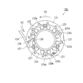
- FIG. 3 shows a state in which the nozzle vane is on the open side. It is the figure which looked at the variable nozzle vane mechanism from the inside of a turbocharger.
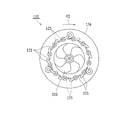
- FIG. 4 shows a state where the nozzle vane is on the open side. It is the figure which looked at the variable nozzle vane mechanism from the outside of the turbocharger.
- FIG. 5 shows a state in which the nozzle vane is on the closed side.
- FIG. 6 shows a state where the nozzle vane is on the closed side.
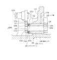
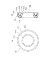
- FIG. 4 is a sectional view taken along the line CC of FIG. 3. It is a figure which writes and shows together the longitudinal cross-sectional view (a) which shows an example of a spring seal, and a front view (b). It is a perspective view which shows a part of spring which comprises the spring seal of FIG. It is a longitudinal cross-sectional view which shows the other example of a spring seal. It is a figure which shows the structure of a wastegate valve apparatus.
- FIG. 11 shows a fully closed valve state. It is a figure which shows the structure of a wastegate valve apparatus.
- FIG. 11 shows a fully closed valve state.
- FIG. 12 is a DD cross-sectional view of FIG. 11.
- a part of the turbine housing is omitted.
- FIG. 1 is a diagram showing a schematic configuration showing an example of an engine 1 mounted on a vehicle.
- the engine 1 of this example is, for example, a common-rail in-cylinder direct injection type four-cylinder diesel engine, and an intake manifold 2 for distributing intake air to each cylinder and exhausted from each cylinder to a cylinder head.
- An exhaust manifold 3 that collects exhaust gas is connected.
- the intake manifold 4 is connected to the inlet of the intake manifold 2 for taking air from the atmosphere and guiding it to the intake manifold 2.
- an air cleaner 6 Arranged in the intake passage 4 are an air cleaner 6, a compressor impeller 102 of a turbocharger 100, which will be described later, an intercooler 8 for forcibly cooling intake air heated by supercharging in the turbocharger 100, and a throttle valve 7.
- an air cleaner 6 Arranged in the intake passage 4 are an air cleaner 6, a compressor impeller 102 of a turbocharger 100, which will be described later, an intercooler 8 for forcibly cooling intake air heated by supercharging in the turbocharger 100, and a throttle valve 7.
- an intercooler 8 for forcibly cooling intake air heated by supercharging in the turbocharger 100
- a NOx storage catalyst (NSR catalyst: NOx Storage Reduction catalyst) 91 and a DPNR catalyst (Diesel Particle-NOx Reduction catalyst) 92 are arranged in the exhaust passage 5.
- NSR catalyst NOx Storage Reduction catalyst
- DPNR catalyst Diesel Particle-NOx Reduction catalyst
- a fuel addition valve 10 for adding fuel to the inside of the exhaust manifold 3 exhaust passage on the upstream side of the exhaust gas flow from the turbine housing 111 is disposed.
- the catalyst bed temperature can be raised, and the NOx absorbed in the NOx catalyst is released and reduced, and the NOx absorption of the NOx catalyst is achieved.
- Ability can be restored.
- fuel may be supplied to the exhaust passage on the upstream side of the catalyst by post injection from the fuel injection valve (injector) of the engine 1 instead of such fuel addition from the fuel addition valve 10.
- the engine 1 is equipped with a turbocharger (supercharger) 100 that supercharges intake air using exhaust pressure.
- a turbocharger supercharger 100 that supercharges intake air using exhaust pressure.
- the turbocharger 100 rotates the turbine wheel 101 disposed in the exhaust passage 5, the compressor impeller 102 disposed in the intake passage 4, and the turbine wheel 101 and the compressor impeller 102.
- the turbine shaft 101 arranged in the exhaust passage 5 is rotated by the energy of the exhaust, and the compressor impeller 102 arranged in the intake passage 4 is rotated accordingly.
- the intake air is supercharged by the rotation of the compressor impeller 102, and the supercharged air is forcibly sent into the combustion chamber of each cylinder of the engine 1.
- the turbine wheel 101 is accommodated in the turbine housing 111, and the compressor impeller 102 is accommodated in the compressor housing 112.
- the floating bearings 103 a and 103 a that support the connecting shaft 103 are accommodated in a center housing (bearing housing) 113, and the turbine housing 111 and the compressor housing 112 are attached to both sides of the center housing 113.
- the turbocharger 100 of this example is a variable nozzle type turbocharger (VNT), and a variable nozzle vane mechanism 120 is provided on the turbine wheel 101 side.
- VNT variable nozzle type turbocharger
- the supercharging pressure can be adjusted. Details of the variable nozzle vane mechanism 120 will be described later.
- an exhaust bypass passage 115 is formed in the turbine housing 111, and a wastegate valve 201 for opening and closing the exhaust bypass passage 115 is provided. It has been. Details of the wastegate valve device 200 including the wastegate valve 201 and the WGV actuator 204 will be described later.
- the engine 1 is equipped with an EGR device 130.
- the EGR device 130 is a device that reduces the combustion temperature in the combustion chamber and reduces the amount of NOx generated by introducing a part of the exhaust gas into the intake air.
- the EGR device 130 includes an EGR passage (exhaust gas recirculation passage) 131 as shown in FIG.
- One end of the EGR passage 131 is connected to the intake passage 4 between the intake manifold 2 and the throttle valve 7.
- the other end of the EGR passage 131 is connected to the exhaust manifold 3, and a part of the exhaust gas (EGR gas) is introduced into the intake passage 4 through the EGR passage 131.
- EGR gas a gas having a higher specific heat than that of air and a smaller amount of oxygen
- an EGR valve 134 for opening and closing the EGR passage 131 is provided.
- An EGR cooler 132 for cooling the EGR gas flowing in the EGR passage 131 is provided upstream (exhaust side) of the EGR valve 134 in the EGR passage 131. Cooling by the EGR cooler 132 increases the density of EGR gas, and the EGR rate can be improved while securing the intake air amount.
- the EGR device 130 is provided with an EGR bypass passage 131a for bypassing the EGR cooler 132 and allowing EGR gas to flow.
- a switching control valve 133 that adjusts the opening degree of the EGR passage 131 and the opening degree of the EGR bypass passage 131a is provided at a connection portion (a connection portion on the downstream side of the EGR gas flow) between the EGR bypass passage 131a and the EGR passage 131. Is provided.
- variable nozzle vane mechanism 120 of the turbocharger 100 will be described with reference to FIGS.
- variable nozzle vane mechanism 120 of this example is disposed in a link chamber 114 formed between the turbine housing 111 and the center housing 113 of the turbocharger 100.
- the variable nozzle vane mechanism 120 includes a plurality (for example, twelve) of nozzle vanes 121... 121, an annular unison ring 122, and a plurality of parts that are partially engaged with the unison ring 122. Open / close arms 123, 123, drive arms 124 for driving the open / close arms 123, vane shafts 125 connected to the open / close arms 123 for driving the nozzle vanes 121, and the vane shafts 125. And a nozzle plate 126 for holding.
- the plurality of nozzle vanes 121... 121 are arranged at equal intervals on the outer peripheral side of the turbine wheel 101.
- Each nozzle vane 121 is disposed on a nozzle plate 126 and can be rotated by a predetermined angle about the vane shaft 125.
- the drive arm 124 is rotatable around the drive shaft 128.
- the drive shaft 128 is integrally attached to one end of the drive link 127. When the drive link 127 is rotated, the drive shaft 128 is rotated in accordance with this rotation, and the drive arm 124 is rotated (oscillated). )
- the drive shaft 128 passes through the wall of the center housing 113 and is disposed facing the inside and the outside (atmosphere side) of the link chamber 114, respectively.
- the drive shaft 128 is rotatably supported by the center housing 113 via the bush 104. The support structure of the drive shaft 128 will be described later.
- each open / close arm 123 is fitted to the inner peripheral surface of the unison ring 122, and when the unison ring 122 rotates, this rotational force is transmitted to each open / close arm 123.
- the unison ring 122 is disposed so as to be slidable in the circumferential direction with respect to the nozzle plate 126.
- the outer peripheral side end portions of the drive arm 124 and the respective opening / closing arms 123 are fitted into a plurality of recesses 122 a provided on the inner peripheral edge of the unison ring 122, and the rotational force of the unison ring 122 is transmitted to each opening / closing arm 123.
- Each open / close arm 123 is rotatable about a vane shaft 125.
- Each vane shaft 125 is rotatably supported by a nozzle plate 126, and the open / close arm 123 and the nozzle vane 121 are integrally connected by the vane shaft 125.
- the nozzle plate 126 is fixed to the turbine housing 111.
- a pin 126a (see FIGS. 3 and 5) is inserted into the nozzle plate 126, and a roller 126b is fitted into the pin 126a.
- the roller 126b guides the inner peripheral surface of the unison ring 122. As a result, the unison ring 122 is held by the roller 126b and can rotate in a predetermined direction.
- the link rod 129 is rotatably connected to the other end of the drive link 127 via a connecting pin 127a.
- the link rod 129 is connected to the VN actuator 106.
- the link rod 129 is moved (advanced / retreated) by the VN actuator 106, the drive link 127 is rotated, and each nozzle vane 121 is rotated accordingly. Move (displace).
- each nozzle vane 121 rotates about the vane shaft 125 in the counterclockwise direction (Y1 direction) in the figure, and the nozzle vane opening (VN opening) is set large.
- Examples of the VN actuator 106 include an electric motor (DC motor) and a conversion mechanism (for example, a worm gear and a worm wheel that meshes with the worm gear) that converts the rotation of the electric motor into a linear motion and transmits the linear motion to the link rod 129. And a gear mechanism having Further, as the VN actuator 106, a negative pressure actuator that operates using a negative pressure supplied from a negative pressure source as a power source, or a positive pressure actuator may be used.
- the turbine housing 111 containing the turbine wheel 101 is provided with a turbine housing vortex chamber 111a, and exhaust gas is supplied to the turbine housing vortex chamber 111a.
- the turbine wheel 101 is rotated by the gas flow.
- the rotational position of each nozzle vane 121 is adjusted, and the rotational angle of the nozzle vane 121 is set to adjust the flow rate and flow velocity of the exhaust from the turbine housing vortex chamber 111a to the turbine wheel 101. it can. This makes it possible to adjust the supercharging performance.
- each nozzle vane 121 so as to reduce the flow path area (throat area) between the nozzle vanes 121 when the engine 1 rotates at a low speed. Is adjusted, the flow rate of the exhaust gas increases, and a high boost pressure can be obtained from the engine low speed range.
- FIG. 7 is a cross-sectional view taken along the line CC of FIG.
- a bush support hole 113a is provided in the wall of the center housing 113 forming the link chamber 114, and a cylindrical bush 104 is press-fitted into the bush support hole 113a.
- a drive shaft 128 is rotatably supported by the bush 104. The drive shaft 128 and the bush 104 pass through the wall of the center housing 113 and are disposed facing the inside of the link chamber 114 and the outside (atmosphere side).
- the drive link 127 is integrally attached to the end of the drive shaft 128 on the outside air side (the outside of the link chamber 114).
- the drive arm 124 is integrally attached to the end of the drive shaft 128 on the link chamber 114 side (turbo housing side).
- the drive link 127 outside the link chamber 114 (outside the center housing 113) and the drive arm 124 in the link chamber 114 are connected via the drive shaft 128, and driven by the driving force of the VN actuator 106.
- the rotational force is transmitted to the drive arm 124 through the drive shaft 128, and the drive arm 124 rotates.
- each nozzle vane 121 described above rotates (displaces).
- a clearance is provided between the outer peripheral surface of the drive shaft 128 and the inner peripheral surface of the bush 104 so that the drive shaft 128 can rotate.
- the distance between the side surface 124a (the surface on the bush 104 side) of the drive arm 124 and the side surface 127a (the surface on the bush 104 side) of the drive link 127 is the axial length of the bush 104 (both end surfaces 104a of the bush 104).
- 104b) is set larger by a predetermined amount than the side surface 124a of the drive arm 124 and the end surface 104a of the bush 104 (the end surface on the inside of the link chamber 114), and the side surface 127a of the drive link 127.
- exhaust gas from the turbine housing 111 flows into the link chamber 114 that houses the variable nozzle vane mechanism (link mechanism) 120.
- This exhaust gas contains unburned fuel (unburned HC).
- unburned HC unburned fuel
- the amount of unburned HC contained in the exhaust gas increases.
- generally iron is used for the center housing 113 of the turbocharger 100.
- the snow melting agent or the like adheres to the center housing 113 and rust is generated.
- rust is generated in the center housing 113 due to mud, water droplets or the like in a road unpaved area or a rainforest area.
- the peeled rust is removed between the drive shaft 128 and the bush 104 or the end face of the bush 104 (end face inside the link chamber 114) by exhaust pulsation.
- the drive arm 124, the movement of the variable nozzle vane mechanism 120 and the like may deteriorate.
- a spring seal 105 is provided at the end on the outside air side of the bush 104 (end on the outside side of the center housing 113).
- the spring seal 105 is fitted into an annular concave portion 141 provided at the outer end of the bush 104.
- the spring seal 105 has a structure in which an annular seal body 151 and a spring 152 are combined.
- the seal body 151 is a molded product or processed product of fluororesin (for example, PTFE).
- the seal body 151 is provided with an annular recess 151f.
- An annular inner lip portion 151a and an outer lip portion 151c are provided on the inner and outer peripheral sides of the recess 151f, respectively.
- the seal body 151 includes an inner peripheral surface 151b (an inner peripheral surface of the inner lip portion 151a) that contacts the outer peripheral surface of the drive shaft 128.
- the seal body 151 includes an outer peripheral surface 151d (an outer peripheral surface of the outer lip portion 151c) that abuts on the inner peripheral surface of the bush 104 (the inner peripheral surface of the annular recess 141). Furthermore, the seal body 151 is formed with an end surface 151e that can contact the drive link 127 provided at the end of the drive shaft 128 on the outer side.
- the spring 152 is a part formed by bending a corrosion-resistant metal plate or the like, and is formed so that a cross-sectional shape cut by a plane passing through the center of the drive shaft 128 (the central axis of the seal body 151) becomes a V shape. Has been.
- the spring 152 is fitted in the recess 151f of the seal body 151 in such a posture that the opening side (V-shaped opening side) faces the link chamber 114 side (the side opposite to the end surface 151e).
- the spring seal 105 having the above structure is folded in a state in which the opening of the recess 151f of the seal body 151 faces the link chamber 114 side (inside the turbo housing) in the recess 141 at the end of the bush 104.
- the curved spring 152 is fitted in a compressed state (a state where the bending angle is reduced).
- the spring 152 is fitted into the recess 151f of the seal body 151 in a compressed state by the outer peripheral surface of the drive shaft 128 and the inner peripheral surface of the bush 104, and the seal body is elastically applied to the spring 152.
- the inner lip 151a of 151 is pressed against the outer peripheral surface of the drive shaft 128, and the outer lip 151c of the seal body 151 is pressed against the inner peripheral surface of the bush 104 (the inner peripheral surface of the recess 141).
- (Tension) can be strengthened.
- the sealing force of the resin seal main body 151 is reduced, the sealing force can be secured by the elastic force of the spring 152, so that high sealing performance can be maintained.
- a spring 152 having a V-shaped cross section is used in the spring seal 105 shown in FIGS. 8 and 9, a spring 152 having a V-shaped cross section is used.
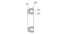
- the center of the drive shaft 128 (the seal body 351) is used.
- a spring seal 305 may be used in which a spring 352 having a U-shaped cross-section cut by a plane passing through the central axis is fitted in the recess 351f of the seal body 351.
- a spring seal having a structure in which the springs 152 and 352 are embedded in the seal main bodies 151 and 351 may be used.
- the spring seal 105 is fitted in the recess 141 at the end of the bush 104 so that the recess 151f of the seal body 151 faces the link chamber 114 side. May be in the opposite direction (the posture in which the concave portion 151f faces the drive link 128 (outside air)).
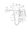
- the waste gate valve device 200 of this example includes a waste gate valve 201, a link mechanism 202, a WGS actuator 204, and the like.
- an exhaust bypass passage 115 that bypasses the turbine wheel 101 is formed in the turbine housing 111 of this example.
- the exhaust bypass passage 115 includes a circular waste gate hole 115a penetrating the wall body 111b of the turbine housing 111, and communicates with the upstream side (upstream side of the exhaust gas flow) of the turbine wheel 101 and the exhaust gas outlet passage 111e. is doing.
- a valve seat (valve seat) 116 is provided at the peripheral portion of the waste gate hole 115a (peripheral portion on the exhaust gas outlet passage 111e side).
- the wastegate valve 201 is a circular valve body 211 that opens or closes the exhaust bypass passage 115 by being seated or separated from the valve seat 116 provided in the turbine housing 111, and the valve body 211 is opened and closed (the valve seat 116). And a drive arm 212 that moves in the direction of contact with and away from the valve). By swinging the drive arm 212, the valve body 211 is closed at the exhaust bypass passage 115 (fully closed position: FIG. 11). The exhaust bypass passage 115 can be moved between the fully open position (fully opened position: FIG. 12).
- the valve seat 116 of the turbine housing 111 is also included in the constituent members of the waste gate valve 201.
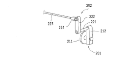
- the drive arm 212 of the wastegate valve 201 is integrally attached to one end of the drive shaft 221 (end on the inner side of the turbine housing 111).
- a drive link 222 is integrally attached to the other end portion (external end portion) of the drive shaft 221.
- the drive shaft 221 is rotatably supported by the bush 203.
- the bush 203 is a cylindrical member, and is press-fitted into a bush support hole 111d provided in the wall 111c of the turbine housing 111 (see FIG. 15).
- the bush 203 and the drive shaft 221 pass through the wall of the turbine housing 111 and are arranged facing the inside and outside (atmosphere side) of the turbine housing 111, respectively.
- one end of the link rod 223 is rotatably connected to the other end of the drive link 222 via a connecting pin 224.
- the link rod 223 is connected to the WGV actuator 204.
- the link rod 223 is moved (advanced / retreated) by the WGV actuator 204, the drive link 222 and the drive shaft 221 are rotated to swing the drive arm 212.
- the valve body 211 moves between the fully closed position (FIG. 11) and the fully open position (FIG. 12).
- the waste gate valve 201 opens and closes.
- the WGV actuator 204 may be a negative pressure actuator that operates using a negative pressure supplied from a negative pressure source as a power source, or may be a positive pressure actuator.
- the WGV actuator 204 may be an electric actuator that uses an electric motor as a drive source.
- a clearance is provided between the outer peripheral surface of the drive shaft 221 and the inner peripheral surface of the bush 203 so that the drive shaft 221 can rotate.
- the distance between the side surface 212a of the drive arm 212 (surface on the bush 203 side) and the side surface 222a of the drive link 222 (surface on the bush 203 side) is the axial length of the bush 203 (both end surfaces 203a of the bush 203).
- 203b) is set to be larger by a predetermined amount than the side surface 212a of the drive arm 212 and the end surface 203a of the bush 203 (end surface on the inner side of the turbine housing 111), and the side surface 222a of the drive link 222.
- the spring seal 105 is provided at the end on the outside air side of the bush 203 (end on the outside side of the turbine housing 111).
- the spring seal 105 is fitted into an annular recess 231 provided at the outer end of the bush 203.
- the spring seal 105 has the same structure as that shown in FIGS. 8 and 9, and therefore, even in the structure shown in FIG. 15, the exhaust gas in the turbine housing 111 does not move between the outer peripheral surface of the drive shaft 221 and the bush 203. It is possible to reliably prevent outflow to the outside through the inner peripheral surface.
- the peeled rust is between the drive shaft 221 and the bush 203 or the end surface 203a of the bush 203 (end surface on the inner side of the turbine housing 111). It is possible to prevent entry into the side surface 212a of the drive arm 212. In addition, the problem of deposit accumulation that occurs due to the adhesion and alteration (coking) of the unburned HC is also eliminated.
- the present invention is not limited to this, and can be applied to a diesel engine having any other number of cylinders such as a six-cylinder diesel engine.
- the present invention is applicable to a turbocharger equipped in an engine (internal combustion engine), and more specifically, a drive shaft that transmits a driving force of an actuator arranged outside the turbo housing to a mechanism inside the turbo housing;
- the present invention can be effectively used for sealing a penetrating portion of the drive shaft of a turbocharger provided with a bush that rotatably supports the drive shaft.
Landscapes
- Engineering & Computer Science (AREA)
- Mechanical Engineering (AREA)
- General Engineering & Computer Science (AREA)
- Chemical & Material Sciences (AREA)
- Combustion & Propulsion (AREA)
- Supercharger (AREA)
Abstract
Description
まず、本発明のターボチャージャを適用するエンジン(内燃機関)について説明する。
エンジン1には、排気圧を利用して吸入空気を過給するターボチャージャ(過給機)100が装備されている。
また、エンジン1にはEGR装置130が装備されている。EGR装置130は、吸入空気に排気ガスの一部を導入することで、燃焼室内の燃焼温度を低下させてNOxの発生量を低減させる装置である。
次に、ターボチャージャ100の可変ノズルベーン機構120について図1~図7を参照して説明する。
次に、可変ノズルベーン機構120の駆動シャフト128の支持構造について図7を参照して説明する。図7は図3のC-C断面図である。
次に、ウエストゲートバルブ装置200について図11~図15を参照して説明する。
以上の例では、可変ノズルベーン機構とウエストゲートバルブとを備えたターボチャージャに本発明を適用した場合について説明したが、本発明はこれに限られることなく、可変ノズルベーン機構またはウエストゲートバルブのいずれか一方を備えたターボチャージャにも適用可能である。
4 吸気通路
5 排気通路
100 ターボチャージャ
101 タービンホイール
102 コンプレッサインペラ
111 タービンハウジング(ターボハウジング)
112 コンプレッサハウジング(ターボハウジング)
113 センターハウジング(ターボハウジング)
114 リンク室
115 排気バイパス通路
115a ウエストゲート穴
120 可変ノズルベーン機構
124 駆動アーム
127 駆動リンク
128 駆動シャフト
129 リンクロッド
104 ブッシュ
141 凹部
105 スプリングシール
151 シール本体
151a 内リップ部
151b 内周面
151c 外リップ部
151d 外周面
151e 端面
151f 凹部
152 スプリング
106 VNアクチュエータ
200 ウエストゲートバルブ装置
201 ウエストゲートバルブ
212 駆動アーム
202 リンク機構
221 駆動シャフト
222 駆動リンク
223 リンクロッド
224 連結ピン
203 ブッシュ
231 凹部
204 WGVアクチュエータ
Claims (5)
- 内燃機関の吸気通路に設けられたコンプレッサインペラと、前記内燃機関の排気通路に設けられたタービンホイールと、ターボハウジングを貫通して設けられ、前記ターボハウジングの外部に配置されるアクチュエータの駆動力を当該ターボハウジング内の駆動機構に伝達する駆動シャフトと、前記駆動シャフトを回転自在な状態で前記ターボハウジングに支持するブッシュとを備えたターボチャージャにおいて、
前記ブッシュの前記ターボハウジング外部側の端部にシールが設けられており、
前記シールは、前記駆動シャフトの外周面に接触する内周面と、前記駆動シャフトの前記ターボハウジング外部側に設けられた部材に接触可能な端面とを有する円環状の樹脂製のシール本体と、前記シール本体を径方向の内周側及び外周側に向けて押圧する金属製のスプリングとを備えていることをターボチャージャ。 - 請求項1記載のターボチャージャにおいて、
前記シール本体は、周方向に沿う円環状の凹部を有し、前記凹部の内周側及び外周側にそれぞれ内リップ部及び外リップ部が設けられているとともに、このシール本体の前記円環状の凹部に前記スプリングが嵌め込まれており、前記スプリングの弾性力によって、前記シール本体の前記内リップ部が前記駆動シャフトの外周面に押圧され、前記シール本体の前記外リップ部が前記ブッシュの内周面に押圧されていることを特徴とするターボチャージャ。 - 請求項2記載のターボチャージャにおいて、
前記シールは、前記シール本体の凹部の開口が前記ターボハウジング内部側に向くように配置されているとともに、前記スプリングは、前記駆動シャフトの中心を通る平面で切った断面形状が、前記ターボハウジング内部側に口が開く折曲形状に形成されていることを特徴とするターボチャージャ。 - 請求項3記載のターボチャージャにおいて、
前記スプリングの前記断面形状がV形状またはU形状に形成されていることを特徴とするターボチャージャ。 - 請求項1~4のいずれか1つに記載のターボチャージャにおいて、
タービンホイールの外周側に設けられた複数のノズルベーンを有し、前記複数のノズルベーンの開度を変更することによって排気ガスの流れを調整する可変ノズルベーン機構と、ターボハウジング内部の前記可変ノズルベーン機構の駆動アームとターボハウジング外部の駆動リンクとを連結する駆動シャフトと、前記駆動シャフトを回転自在に支持するブッシュとを備え、前記ブッシュの前記ターボハウジング外部側の端部に前記シールが設けられていることを特徴とするターボチャージャ。
Priority Applications (5)
| Application Number | Priority Date | Filing Date | Title |
|---|---|---|---|
| EP11860106.1A EP2543847B1 (en) | 2011-03-31 | 2011-03-31 | Turbocharger |
| CN201180016530.XA CN102822472B (zh) | 2011-03-31 | 2011-03-31 | 涡轮增压器 |
| PCT/JP2011/058285 WO2012131997A1 (ja) | 2011-03-31 | 2011-03-31 | ターボチャージャ |
| US13/522,621 US9175578B2 (en) | 2011-03-31 | 2011-03-31 | Turbocharger |
| JP2012527137A JP5304949B2 (ja) | 2011-03-31 | 2011-03-31 | ターボチャージャ |
Applications Claiming Priority (1)
| Application Number | Priority Date | Filing Date | Title |
|---|---|---|---|
| PCT/JP2011/058285 WO2012131997A1 (ja) | 2011-03-31 | 2011-03-31 | ターボチャージャ |
Publications (1)
| Publication Number | Publication Date |
|---|---|
| WO2012131997A1 true WO2012131997A1 (ja) | 2012-10-04 |
Family
ID=46929817
Family Applications (1)
| Application Number | Title | Priority Date | Filing Date |
|---|---|---|---|
| PCT/JP2011/058285 Ceased WO2012131997A1 (ja) | 2011-03-31 | 2011-03-31 | ターボチャージャ |
Country Status (5)
| Country | Link |
|---|---|
| US (1) | US9175578B2 (ja) |
| EP (1) | EP2543847B1 (ja) |
| JP (1) | JP5304949B2 (ja) |
| CN (1) | CN102822472B (ja) |
| WO (1) | WO2012131997A1 (ja) |
Cited By (5)
| Publication number | Priority date | Publication date | Assignee | Title |
|---|---|---|---|---|
| JP2014190303A (ja) * | 2013-03-28 | 2014-10-06 | Otics Corp | ターボチャージャ |
| JP2015516055A (ja) * | 2012-05-11 | 2015-06-04 | ボーグワーナー インコーポレーテッド | 排気ガスターボチャージャの調節フラップ装置 |
| JPWO2015194436A1 (ja) * | 2014-06-20 | 2017-04-20 | 株式会社Ihi | 過給機 |
| WO2018191214A1 (en) * | 2017-04-11 | 2018-10-18 | Borgwarner Inc. | Face seal assembly for variable turbine geometry turbocharger |
| US10934882B2 (en) | 2018-09-13 | 2021-03-02 | Toyota Jidosha Kabushiki Kaisha | Turbocharger |
Families Citing this family (19)
| Publication number | Priority date | Publication date | Assignee | Title |
|---|---|---|---|---|
| JP6212546B2 (ja) * | 2012-05-29 | 2017-10-11 | ボーグワーナー インコーポレーテッド | 排気ガスターボチャージャ |
| CN103147846B (zh) * | 2013-03-12 | 2015-10-21 | 汉美综合科技(常州)有限公司 | 用于涡轮增压器的可调式喷嘴 |
| JP5807037B2 (ja) * | 2013-05-16 | 2015-11-10 | 株式会社豊田自動織機 | 可変ノズルターボチャージャ |
| DE102013209786B3 (de) * | 2013-05-27 | 2014-01-16 | Bayerische Motoren Werke Aktiengesellschaft | Verfahren zum Prüfen der Dichtheit eines einen Abgasturbolader aufweisenden Verbrennungsmotors sowie Abgasturbolader |
| WO2015001927A1 (ja) * | 2013-07-04 | 2015-01-08 | 株式会社Ihi | アクチュエータの動力伝達機構および過給機 |
| GB201312505D0 (en) * | 2013-07-12 | 2013-08-28 | Cummins Ltd | Turbine |
| CN105683525B (zh) * | 2013-10-23 | 2019-04-02 | 博格华纳公司 | 具有u型密封件的致动枢转轴面密封 |
| JP6217391B2 (ja) * | 2013-12-27 | 2017-10-25 | 株式会社Ihi | 軸受構造および過給機 |
| CN104763510B (zh) * | 2014-11-27 | 2017-06-23 | 宁波吉利罗佑发动机零部件有限公司 | 一种回收排气歧管热量实现发动机增压的系统 |
| US10329948B2 (en) * | 2016-02-10 | 2019-06-25 | Borgwarner Inc. | Stamped variable geometry turbocharger lever using retention collar |
| DE102016203025A1 (de) * | 2016-02-26 | 2017-08-31 | Bosch Mahle Turbo Systems Gmbh & Co. Kg | Variable Turbinengeometrie |
| CN105927588B (zh) * | 2016-04-29 | 2019-09-13 | 沈阳透平机械股份有限公司 | 增压压缩机入口导叶调节装置及方法 |
| CN109690049B (zh) * | 2016-07-27 | 2022-02-08 | 世倍特集团有限责任公司 | 打开和关闭废气门通道的翻盖装置 |
| DE102016117345A1 (de) * | 2016-09-15 | 2018-03-15 | Man Diesel & Turbo Se | Radialturbine eines Turboladers und Turbolader |
| US10590789B2 (en) * | 2017-04-26 | 2020-03-17 | Borgwarner Inc. | Turbocharger radial seal |
| DE102017218050B4 (de) * | 2017-10-10 | 2021-11-04 | Vitesco Technologies GmbH | Turboladereinrichtung mit Federelement zum Verspannen des Leitapparates gegen das Turbinengehäuse und Federelement |
| US10570815B2 (en) | 2017-10-19 | 2020-02-25 | Garrett Transportation I Inc. | Wastegate valve assembly with biasing members |
| JP7405729B2 (ja) * | 2020-11-09 | 2023-12-26 | トヨタ自動車株式会社 | ターボチャージャ |
| WO2024223035A1 (en) * | 2023-04-26 | 2024-10-31 | HELLA GmbH & Co. KGaA | Axial seal for actuator, actuator, and turbocharger with actuator |
Citations (6)
| Publication number | Priority date | Publication date | Assignee | Title |
|---|---|---|---|---|
| JPH11229886A (ja) * | 1998-02-13 | 1999-08-24 | Taiho Kogyo Co Ltd | ターボチャージャのシール装置 |
| WO2005008041A1 (en) * | 2003-07-11 | 2005-01-27 | Malcolm George Leavesley | Turbocharger apparatus having an exhaust gas sealing system for preventing gas leakage from the turbocharger apparatus |
| JP2005351089A (ja) | 2004-06-08 | 2005-12-22 | Ishikawajima Harima Heavy Ind Co Ltd | 過給機およびシール装置 |
| JP2008309111A (ja) * | 2007-06-15 | 2008-12-25 | Toyota Motor Corp | 可変ノズル機構 |
| JP2009299505A (ja) | 2008-06-10 | 2009-12-24 | Toyota Motor Corp | ターボチャージャの制御装置および制御方法 |
| JP2011017326A (ja) | 2009-07-10 | 2011-01-27 | Ihi Corp | 可変容量型ターボチャージャ |
Family Cites Families (9)
| Publication number | Priority date | Publication date | Assignee | Title |
|---|---|---|---|---|
| JPH0415953Y2 (ja) * | 1985-07-08 | 1992-04-09 | ||
| JPH05248253A (ja) * | 1992-03-09 | 1993-09-24 | Aisan Ind Co Ltd | ターボチャージャ用ウェストゲートバルブ |
| US5799953A (en) * | 1995-05-25 | 1998-09-01 | American Variseal | Capped spring-energized seal |
| JPH09303153A (ja) * | 1996-05-13 | 1997-11-25 | Yokohama Rubber Co Ltd:The | ターボチャージャ・ウェイストゲート用アクチュエータ |
| US7475540B2 (en) * | 2002-11-19 | 2009-01-13 | Holset Engineering Co., Limited | Variable geometry turbine |
| JP2005113797A (ja) * | 2003-10-08 | 2005-04-28 | Aisin Seiki Co Ltd | ターボチャージャの排気ガスシール構造 |
| JP2009167855A (ja) | 2008-01-15 | 2009-07-30 | Toyota Motor Corp | 過給機の可変ノズル装置 |
| JP2009270537A (ja) | 2008-05-09 | 2009-11-19 | Toyota Motor Corp | ターボチャージャ |
| US8579579B2 (en) * | 2009-11-10 | 2013-11-12 | Honeywell International Inc. | Sealed shaft assembly for exhaust turbines |
-
2011
- 2011-03-31 WO PCT/JP2011/058285 patent/WO2012131997A1/ja not_active Ceased
- 2011-03-31 CN CN201180016530.XA patent/CN102822472B/zh active Active
- 2011-03-31 US US13/522,621 patent/US9175578B2/en active Active
- 2011-03-31 EP EP11860106.1A patent/EP2543847B1/en active Active
- 2011-03-31 JP JP2012527137A patent/JP5304949B2/ja active Active
Patent Citations (6)
| Publication number | Priority date | Publication date | Assignee | Title |
|---|---|---|---|---|
| JPH11229886A (ja) * | 1998-02-13 | 1999-08-24 | Taiho Kogyo Co Ltd | ターボチャージャのシール装置 |
| WO2005008041A1 (en) * | 2003-07-11 | 2005-01-27 | Malcolm George Leavesley | Turbocharger apparatus having an exhaust gas sealing system for preventing gas leakage from the turbocharger apparatus |
| JP2005351089A (ja) | 2004-06-08 | 2005-12-22 | Ishikawajima Harima Heavy Ind Co Ltd | 過給機およびシール装置 |
| JP2008309111A (ja) * | 2007-06-15 | 2008-12-25 | Toyota Motor Corp | 可変ノズル機構 |
| JP2009299505A (ja) | 2008-06-10 | 2009-12-24 | Toyota Motor Corp | ターボチャージャの制御装置および制御方法 |
| JP2011017326A (ja) | 2009-07-10 | 2011-01-27 | Ihi Corp | 可変容量型ターボチャージャ |
Non-Patent Citations (1)
| Title |
|---|
| See also references of EP2543847A4 * |
Cited By (7)
| Publication number | Priority date | Publication date | Assignee | Title |
|---|---|---|---|---|
| JP2015516055A (ja) * | 2012-05-11 | 2015-06-04 | ボーグワーナー インコーポレーテッド | 排気ガスターボチャージャの調節フラップ装置 |
| JP2014190303A (ja) * | 2013-03-28 | 2014-10-06 | Otics Corp | ターボチャージャ |
| JPWO2015194436A1 (ja) * | 2014-06-20 | 2017-04-20 | 株式会社Ihi | 過給機 |
| US10465599B2 (en) | 2014-06-20 | 2019-11-05 | Ihi Corporation | Turbocharger |
| WO2018191214A1 (en) * | 2017-04-11 | 2018-10-18 | Borgwarner Inc. | Face seal assembly for variable turbine geometry turbocharger |
| US10577958B2 (en) | 2017-04-11 | 2020-03-03 | Borgwarner Inc. | Face seal assembly for variable turbine geometry turbocharger |
| US10934882B2 (en) | 2018-09-13 | 2021-03-02 | Toyota Jidosha Kabushiki Kaisha | Turbocharger |
Also Published As
| Publication number | Publication date |
|---|---|
| CN102822472A (zh) | 2012-12-12 |
| US9175578B2 (en) | 2015-11-03 |
| JPWO2012131997A1 (ja) | 2014-07-24 |
| JP5304949B2 (ja) | 2013-10-02 |
| EP2543847A1 (en) | 2013-01-09 |
| CN102822472B (zh) | 2015-01-28 |
| EP2543847A4 (en) | 2015-03-11 |
| EP2543847B1 (en) | 2016-10-05 |
| US20120328416A1 (en) | 2012-12-27 |
Similar Documents
| Publication | Publication Date | Title |
|---|---|---|
| JP5304949B2 (ja) | ターボチャージャ | |
| US9109708B2 (en) | Engine breathing system valve and products including the same | |
| CN101341319B (zh) | 制造多级排气涡轮增压器的方法 | |
| US8844282B2 (en) | Exhaust-gas turbocharger having a ball-cock waste-gate valve with a stress-relieved crank arm | |
| JP2010014271A (ja) | 弁調整組立体 | |
| US10934945B2 (en) | Internal combustion engine with compressor, exhaust-gas recirculation arrangement and pivotable flap | |
| JP5699662B2 (ja) | 内燃機関の排気装置 | |
| EP2915976B1 (en) | Turbocharger turbine wastegate mechanism | |
| JP2012062808A (ja) | 可変容量型ターボチャージャ | |
| EP2625402B1 (en) | Engine breathing system valve and seal | |
| JP6040918B2 (ja) | Egrバルブ装置 | |
| EP2915975B1 (en) | Turbocharger turbine wastegate mechanism | |
| JP2013002302A (ja) | 内燃機関の排気装置 | |
| US20180058340A1 (en) | Supercharged internal combustion engine with compressor, exhaust-gas recirculation arrangement and flap | |
| JP2009270537A (ja) | ターボチャージャ | |
| US20060053789A1 (en) | Exhaust gas regulating element for supercharger systems of internal combustion engines | |
| JP2013053580A (ja) | ターボチャージャ | |
| JP5742538B2 (ja) | 内燃機関の排気装置 | |
| US9708970B2 (en) | Housing for turbocharger | |
| JP2009275574A (ja) | 可変容量型ターボチャージャ | |
| JP2009281295A (ja) | 可変容量型ターボチャージャ | |
| JP4816481B2 (ja) | 可変容量型ターボチャージャ | |
| CN110662896B (zh) | 一体型背压及egr阀模块 | |
| JP2010037994A (ja) | 内燃機関 | |
| JP4862635B2 (ja) | 過給機付内燃機関 |
Legal Events
| Date | Code | Title | Description |
|---|---|---|---|
| WWE | Wipo information: entry into national phase |
Ref document number: 201180016530.X Country of ref document: CN |
|
| ENP | Entry into the national phase |
Ref document number: 2012527137 Country of ref document: JP Kind code of ref document: A |
|
| WWE | Wipo information: entry into national phase |
Ref document number: 13522621 Country of ref document: US |
|
| REEP | Request for entry into the european phase |
Ref document number: 2011860106 Country of ref document: EP |
|
| WWE | Wipo information: entry into national phase |
Ref document number: 2011860106 Country of ref document: EP |
|
| 121 | Ep: the epo has been informed by wipo that ep was designated in this application |
Ref document number: 11860106 Country of ref document: EP Kind code of ref document: A1 |
|
| NENP | Non-entry into the national phase |
Ref country code: DE |