WO2012132405A1 - 車載充電装置 - Google Patents
車載充電装置 Download PDFInfo
- Publication number
- WO2012132405A1 WO2012132405A1 PCT/JP2012/002109 JP2012002109W WO2012132405A1 WO 2012132405 A1 WO2012132405 A1 WO 2012132405A1 JP 2012002109 W JP2012002109 W JP 2012002109W WO 2012132405 A1 WO2012132405 A1 WO 2012132405A1
- Authority
- WO
- WIPO (PCT)
- Prior art keywords
- vehicle
- information
- vehicle information
- storage unit
- control unit
- Prior art date
- Legal status (The legal status is an assumption and is not a legal conclusion. Google has not performed a legal analysis and makes no representation as to the accuracy of the status listed.)
- Ceased
Links
Images





Classifications
-
- B—PERFORMING OPERATIONS; TRANSPORTING
- B60—VEHICLES IN GENERAL
- B60L—PROPULSION OF ELECTRICALLY-PROPELLED VEHICLES; SUPPLYING ELECTRIC POWER FOR AUXILIARY EQUIPMENT OF ELECTRICALLY-PROPELLED VEHICLES; ELECTRODYNAMIC BRAKE SYSTEMS FOR VEHICLES IN GENERAL; MAGNETIC SUSPENSION OR LEVITATION FOR VEHICLES; MONITORING OPERATING VARIABLES OF ELECTRICALLY-PROPELLED VEHICLES; ELECTRIC SAFETY DEVICES FOR ELECTRICALLY-PROPELLED VEHICLES
- B60L53/00—Methods of charging batteries, specially adapted for electric vehicles; Charging stations or on-board charging equipment therefor; Exchange of energy storage elements in electric vehicles
- B60L53/10—Methods of charging batteries, specially adapted for electric vehicles; Charging stations or on-board charging equipment therefor; Exchange of energy storage elements in electric vehicles characterised by the energy transfer between the charging station and the vehicle
- B60L53/14—Conductive energy transfer
-
- H—ELECTRICITY
- H02—GENERATION; CONVERSION OR DISTRIBUTION OF ELECTRIC POWER
- H02J—ELECTRIC POWER NETWORKS; CIRCUIT ARRANGEMENTS OR SYSTEMS FOR SUPPLYING OR DISTRIBUTING ELECTRIC POWER; SYSTEMS FOR STORING ELECTRIC ENERGY
- H02J7/00—Circuit arrangements for charging or discharging batteries or for supplying loads from batteries
- H02J7/485—Circuit arrangements for charging or discharging batteries or for supplying loads from batteries with provisions for charging different types of batteries
-
- B—PERFORMING OPERATIONS; TRANSPORTING
- B60—VEHICLES IN GENERAL
- B60L—PROPULSION OF ELECTRICALLY-PROPELLED VEHICLES; SUPPLYING ELECTRIC POWER FOR AUXILIARY EQUIPMENT OF ELECTRICALLY-PROPELLED VEHICLES; ELECTRODYNAMIC BRAKE SYSTEMS FOR VEHICLES IN GENERAL; MAGNETIC SUSPENSION OR LEVITATION FOR VEHICLES; MONITORING OPERATING VARIABLES OF ELECTRICALLY-PROPELLED VEHICLES; ELECTRIC SAFETY DEVICES FOR ELECTRICALLY-PROPELLED VEHICLES
- B60L1/00—Supplying electric power to auxiliary equipment of vehicles
- B60L1/003—Supplying electric power to auxiliary equipment of vehicles to auxiliary motors, e.g. for pumps, compressors
-
- B—PERFORMING OPERATIONS; TRANSPORTING
- B60—VEHICLES IN GENERAL
- B60L—PROPULSION OF ELECTRICALLY-PROPELLED VEHICLES; SUPPLYING ELECTRIC POWER FOR AUXILIARY EQUIPMENT OF ELECTRICALLY-PROPELLED VEHICLES; ELECTRODYNAMIC BRAKE SYSTEMS FOR VEHICLES IN GENERAL; MAGNETIC SUSPENSION OR LEVITATION FOR VEHICLES; MONITORING OPERATING VARIABLES OF ELECTRICALLY-PROPELLED VEHICLES; ELECTRIC SAFETY DEVICES FOR ELECTRICALLY-PROPELLED VEHICLES
- B60L3/00—Electric devices on electrically-propelled vehicles for safety purposes; Monitoring operating variables, e.g. speed, deceleration or energy consumption
- B60L3/0023—Detecting, eliminating, remedying or compensating for drive train abnormalities, e.g. failures within the drive train
- B60L3/0069—Detecting, eliminating, remedying or compensating for drive train abnormalities, e.g. failures within the drive train relating to the isolation, e.g. ground fault or leak current
-
- B—PERFORMING OPERATIONS; TRANSPORTING
- B60—VEHICLES IN GENERAL
- B60L—PROPULSION OF ELECTRICALLY-PROPELLED VEHICLES; SUPPLYING ELECTRIC POWER FOR AUXILIARY EQUIPMENT OF ELECTRICALLY-PROPELLED VEHICLES; ELECTRODYNAMIC BRAKE SYSTEMS FOR VEHICLES IN GENERAL; MAGNETIC SUSPENSION OR LEVITATION FOR VEHICLES; MONITORING OPERATING VARIABLES OF ELECTRICALLY-PROPELLED VEHICLES; ELECTRIC SAFETY DEVICES FOR ELECTRICALLY-PROPELLED VEHICLES
- B60L3/00—Electric devices on electrically-propelled vehicles for safety purposes; Monitoring operating variables, e.g. speed, deceleration or energy consumption
- B60L3/04—Cutting off the power supply under fault conditions
-
- B—PERFORMING OPERATIONS; TRANSPORTING
- B60—VEHICLES IN GENERAL
- B60L—PROPULSION OF ELECTRICALLY-PROPELLED VEHICLES; SUPPLYING ELECTRIC POWER FOR AUXILIARY EQUIPMENT OF ELECTRICALLY-PROPELLED VEHICLES; ELECTRODYNAMIC BRAKE SYSTEMS FOR VEHICLES IN GENERAL; MAGNETIC SUSPENSION OR LEVITATION FOR VEHICLES; MONITORING OPERATING VARIABLES OF ELECTRICALLY-PROPELLED VEHICLES; ELECTRIC SAFETY DEVICES FOR ELECTRICALLY-PROPELLED VEHICLES
- B60L53/00—Methods of charging batteries, specially adapted for electric vehicles; Charging stations or on-board charging equipment therefor; Exchange of energy storage elements in electric vehicles
- B60L53/10—Methods of charging batteries, specially adapted for electric vehicles; Charging stations or on-board charging equipment therefor; Exchange of energy storage elements in electric vehicles characterised by the energy transfer between the charging station and the vehicle
- B60L53/14—Conductive energy transfer
- B60L53/16—Connectors, e.g. plugs or sockets, specially adapted for charging electric vehicles
-
- B—PERFORMING OPERATIONS; TRANSPORTING
- B60—VEHICLES IN GENERAL
- B60L—PROPULSION OF ELECTRICALLY-PROPELLED VEHICLES; SUPPLYING ELECTRIC POWER FOR AUXILIARY EQUIPMENT OF ELECTRICALLY-PROPELLED VEHICLES; ELECTRODYNAMIC BRAKE SYSTEMS FOR VEHICLES IN GENERAL; MAGNETIC SUSPENSION OR LEVITATION FOR VEHICLES; MONITORING OPERATING VARIABLES OF ELECTRICALLY-PROPELLED VEHICLES; ELECTRIC SAFETY DEVICES FOR ELECTRICALLY-PROPELLED VEHICLES
- B60L53/00—Methods of charging batteries, specially adapted for electric vehicles; Charging stations or on-board charging equipment therefor; Exchange of energy storage elements in electric vehicles
- B60L53/10—Methods of charging batteries, specially adapted for electric vehicles; Charging stations or on-board charging equipment therefor; Exchange of energy storage elements in electric vehicles characterised by the energy transfer between the charging station and the vehicle
- B60L53/14—Conductive energy transfer
- B60L53/18—Cables specially adapted for charging electric vehicles
-
- B—PERFORMING OPERATIONS; TRANSPORTING
- B60—VEHICLES IN GENERAL
- B60L—PROPULSION OF ELECTRICALLY-PROPELLED VEHICLES; SUPPLYING ELECTRIC POWER FOR AUXILIARY EQUIPMENT OF ELECTRICALLY-PROPELLED VEHICLES; ELECTRODYNAMIC BRAKE SYSTEMS FOR VEHICLES IN GENERAL; MAGNETIC SUSPENSION OR LEVITATION FOR VEHICLES; MONITORING OPERATING VARIABLES OF ELECTRICALLY-PROPELLED VEHICLES; ELECTRIC SAFETY DEVICES FOR ELECTRICALLY-PROPELLED VEHICLES
- B60L53/00—Methods of charging batteries, specially adapted for electric vehicles; Charging stations or on-board charging equipment therefor; Exchange of energy storage elements in electric vehicles
- B60L53/60—Monitoring or controlling charging stations
- B60L53/65—Monitoring or controlling charging stations involving identification of vehicles or their battery types
-
- H—ELECTRICITY
- H01—ELECTRIC ELEMENTS
- H01M—PROCESSES OR MEANS, e.g. BATTERIES, FOR THE DIRECT CONVERSION OF CHEMICAL ENERGY INTO ELECTRICAL ENERGY
- H01M10/00—Secondary cells; Manufacture thereof
- H01M10/42—Methods or arrangements for servicing or maintenance of secondary cells or secondary half-cells
- H01M10/44—Methods for charging or discharging
-
- H—ELECTRICITY
- H02—GENERATION; CONVERSION OR DISTRIBUTION OF ELECTRIC POWER
- H02J—ELECTRIC POWER NETWORKS; CIRCUIT ARRANGEMENTS OR SYSTEMS FOR SUPPLYING OR DISTRIBUTING ELECTRIC POWER; SYSTEMS FOR STORING ELECTRIC ENERGY
- H02J13/00—Circuit arrangements for providing remote monitoring or remote control of equipment in a power distribution network
- H02J13/13—Circuit arrangements for providing remote monitoring or remote control of equipment in a power distribution network characterised by the transmission of data to equipment in the power network
- H02J13/1311—Circuit arrangements for providing remote monitoring or remote control of equipment in a power distribution network characterised by the transmission of data to equipment in the power network using the power network as support for the transmission
- H02J13/1313—Circuit arrangements for providing remote monitoring or remote control of equipment in a power distribution network characterised by the transmission of data to equipment in the power network using the power network as support for the transmission using pulsed signals
-
- H—ELECTRICITY
- H02—GENERATION; CONVERSION OR DISTRIBUTION OF ELECTRIC POWER
- H02J—ELECTRIC POWER NETWORKS; CIRCUIT ARRANGEMENTS OR SYSTEMS FOR SUPPLYING OR DISTRIBUTING ELECTRIC POWER; SYSTEMS FOR STORING ELECTRIC ENERGY
- H02J7/00—Circuit arrangements for charging or discharging batteries or for supplying loads from batteries
- H02J7/40—Circuit arrangements for charging or discharging batteries or for supplying loads from batteries characterised by the exchange of charge or discharge related data
- H02J7/44—Circuit arrangements for charging or discharging batteries or for supplying loads from batteries characterised by the exchange of charge or discharge related data between battery management systems and power sources
-
- H—ELECTRICITY
- H02—GENERATION; CONVERSION OR DISTRIBUTION OF ELECTRIC POWER
- H02J—ELECTRIC POWER NETWORKS; CIRCUIT ARRANGEMENTS OR SYSTEMS FOR SUPPLYING OR DISTRIBUTING ELECTRIC POWER; SYSTEMS FOR STORING ELECTRIC ENERGY
- H02J7/00—Circuit arrangements for charging or discharging batteries or for supplying loads from batteries
- H02J7/60—Circuit arrangements for charging or discharging batteries or for supplying loads from batteries including safety or protection arrangements
- H02J7/663—Circuit arrangements for charging or discharging batteries or for supplying loads from batteries including safety or protection arrangements using battery or load disconnect circuits
-
- B—PERFORMING OPERATIONS; TRANSPORTING
- B60—VEHICLES IN GENERAL
- B60L—PROPULSION OF ELECTRICALLY-PROPELLED VEHICLES; SUPPLYING ELECTRIC POWER FOR AUXILIARY EQUIPMENT OF ELECTRICALLY-PROPELLED VEHICLES; ELECTRODYNAMIC BRAKE SYSTEMS FOR VEHICLES IN GENERAL; MAGNETIC SUSPENSION OR LEVITATION FOR VEHICLES; MONITORING OPERATING VARIABLES OF ELECTRICALLY-PROPELLED VEHICLES; ELECTRIC SAFETY DEVICES FOR ELECTRICALLY-PROPELLED VEHICLES
- B60L2210/00—Converter types
- B60L2210/30—AC to DC converters
-
- B—PERFORMING OPERATIONS; TRANSPORTING
- B60—VEHICLES IN GENERAL
- B60L—PROPULSION OF ELECTRICALLY-PROPELLED VEHICLES; SUPPLYING ELECTRIC POWER FOR AUXILIARY EQUIPMENT OF ELECTRICALLY-PROPELLED VEHICLES; ELECTRODYNAMIC BRAKE SYSTEMS FOR VEHICLES IN GENERAL; MAGNETIC SUSPENSION OR LEVITATION FOR VEHICLES; MONITORING OPERATING VARIABLES OF ELECTRICALLY-PROPELLED VEHICLES; ELECTRIC SAFETY DEVICES FOR ELECTRICALLY-PROPELLED VEHICLES
- B60L2240/00—Control parameters of input or output; Target parameters
- B60L2240/10—Vehicle control parameters
- B60L2240/34—Cabin temperature
-
- B—PERFORMING OPERATIONS; TRANSPORTING
- B60—VEHICLES IN GENERAL
- B60L—PROPULSION OF ELECTRICALLY-PROPELLED VEHICLES; SUPPLYING ELECTRIC POWER FOR AUXILIARY EQUIPMENT OF ELECTRICALLY-PROPELLED VEHICLES; ELECTRODYNAMIC BRAKE SYSTEMS FOR VEHICLES IN GENERAL; MAGNETIC SUSPENSION OR LEVITATION FOR VEHICLES; MONITORING OPERATING VARIABLES OF ELECTRICALLY-PROPELLED VEHICLES; ELECTRIC SAFETY DEVICES FOR ELECTRICALLY-PROPELLED VEHICLES
- B60L2240/00—Control parameters of input or output; Target parameters
- B60L2240/10—Vehicle control parameters
- B60L2240/36—Temperature of vehicle components or parts
-
- B—PERFORMING OPERATIONS; TRANSPORTING
- B60—VEHICLES IN GENERAL
- B60L—PROPULSION OF ELECTRICALLY-PROPELLED VEHICLES; SUPPLYING ELECTRIC POWER FOR AUXILIARY EQUIPMENT OF ELECTRICALLY-PROPELLED VEHICLES; ELECTRODYNAMIC BRAKE SYSTEMS FOR VEHICLES IN GENERAL; MAGNETIC SUSPENSION OR LEVITATION FOR VEHICLES; MONITORING OPERATING VARIABLES OF ELECTRICALLY-PROPELLED VEHICLES; ELECTRIC SAFETY DEVICES FOR ELECTRICALLY-PROPELLED VEHICLES
- B60L2270/00—Problem solutions or means not otherwise provided for
- B60L2270/10—Emission reduction
- B60L2270/14—Emission reduction of noise
- B60L2270/145—Structure borne vibrations
-
- H—ELECTRICITY
- H01—ELECTRIC ELEMENTS
- H01M—PROCESSES OR MEANS, e.g. BATTERIES, FOR THE DIRECT CONVERSION OF CHEMICAL ENERGY INTO ELECTRICAL ENERGY
- H01M2220/00—Batteries for particular applications
- H01M2220/20—Batteries in motive systems, e.g. vehicle, ship, plane
-
- Y—GENERAL TAGGING OF NEW TECHNOLOGICAL DEVELOPMENTS; GENERAL TAGGING OF CROSS-SECTIONAL TECHNOLOGIES SPANNING OVER SEVERAL SECTIONS OF THE IPC; TECHNICAL SUBJECTS COVERED BY FORMER USPC CROSS-REFERENCE ART COLLECTIONS [XRACs] AND DIGESTS
- Y02—TECHNOLOGIES OR APPLICATIONS FOR MITIGATION OR ADAPTATION AGAINST CLIMATE CHANGE
- Y02B—CLIMATE CHANGE MITIGATION TECHNOLOGIES RELATED TO BUILDINGS, e.g. HOUSING, HOUSE APPLIANCES OR RELATED END-USER APPLICATIONS
- Y02B90/00—Enabling technologies or technologies with a potential or indirect contribution to GHG emissions mitigation
- Y02B90/20—Smart grids as enabling technology in buildings sector
-
- Y—GENERAL TAGGING OF NEW TECHNOLOGICAL DEVELOPMENTS; GENERAL TAGGING OF CROSS-SECTIONAL TECHNOLOGIES SPANNING OVER SEVERAL SECTIONS OF THE IPC; TECHNICAL SUBJECTS COVERED BY FORMER USPC CROSS-REFERENCE ART COLLECTIONS [XRACs] AND DIGESTS
- Y02—TECHNOLOGIES OR APPLICATIONS FOR MITIGATION OR ADAPTATION AGAINST CLIMATE CHANGE
- Y02E—REDUCTION OF GREENHOUSE GAS [GHG] EMISSIONS, RELATED TO ENERGY GENERATION, TRANSMISSION OR DISTRIBUTION
- Y02E60/00—Enabling technologies; Technologies with a potential or indirect contribution to GHG emissions mitigation
- Y02E60/10—Energy storage using batteries
-
- Y—GENERAL TAGGING OF NEW TECHNOLOGICAL DEVELOPMENTS; GENERAL TAGGING OF CROSS-SECTIONAL TECHNOLOGIES SPANNING OVER SEVERAL SECTIONS OF THE IPC; TECHNICAL SUBJECTS COVERED BY FORMER USPC CROSS-REFERENCE ART COLLECTIONS [XRACs] AND DIGESTS
- Y02—TECHNOLOGIES OR APPLICATIONS FOR MITIGATION OR ADAPTATION AGAINST CLIMATE CHANGE
- Y02T—CLIMATE CHANGE MITIGATION TECHNOLOGIES RELATED TO TRANSPORTATION
- Y02T10/00—Road transport of goods or passengers
- Y02T10/60—Other road transportation technologies with climate change mitigation effect
- Y02T10/70—Energy storage systems for electromobility, e.g. batteries
-
- Y—GENERAL TAGGING OF NEW TECHNOLOGICAL DEVELOPMENTS; GENERAL TAGGING OF CROSS-SECTIONAL TECHNOLOGIES SPANNING OVER SEVERAL SECTIONS OF THE IPC; TECHNICAL SUBJECTS COVERED BY FORMER USPC CROSS-REFERENCE ART COLLECTIONS [XRACs] AND DIGESTS
- Y02—TECHNOLOGIES OR APPLICATIONS FOR MITIGATION OR ADAPTATION AGAINST CLIMATE CHANGE
- Y02T—CLIMATE CHANGE MITIGATION TECHNOLOGIES RELATED TO TRANSPORTATION
- Y02T10/00—Road transport of goods or passengers
- Y02T10/60—Other road transportation technologies with climate change mitigation effect
- Y02T10/7072—Electromobility specific charging systems or methods for batteries, ultracapacitors, supercapacitors or double-layer capacitors
-
- Y—GENERAL TAGGING OF NEW TECHNOLOGICAL DEVELOPMENTS; GENERAL TAGGING OF CROSS-SECTIONAL TECHNOLOGIES SPANNING OVER SEVERAL SECTIONS OF THE IPC; TECHNICAL SUBJECTS COVERED BY FORMER USPC CROSS-REFERENCE ART COLLECTIONS [XRACs] AND DIGESTS
- Y02—TECHNOLOGIES OR APPLICATIONS FOR MITIGATION OR ADAPTATION AGAINST CLIMATE CHANGE
- Y02T—CLIMATE CHANGE MITIGATION TECHNOLOGIES RELATED TO TRANSPORTATION
- Y02T10/00—Road transport of goods or passengers
- Y02T10/60—Other road transportation technologies with climate change mitigation effect
- Y02T10/72—Electric energy management in electromobility
-
- Y—GENERAL TAGGING OF NEW TECHNOLOGICAL DEVELOPMENTS; GENERAL TAGGING OF CROSS-SECTIONAL TECHNOLOGIES SPANNING OVER SEVERAL SECTIONS OF THE IPC; TECHNICAL SUBJECTS COVERED BY FORMER USPC CROSS-REFERENCE ART COLLECTIONS [XRACs] AND DIGESTS
- Y02—TECHNOLOGIES OR APPLICATIONS FOR MITIGATION OR ADAPTATION AGAINST CLIMATE CHANGE
- Y02T—CLIMATE CHANGE MITIGATION TECHNOLOGIES RELATED TO TRANSPORTATION
- Y02T90/00—Enabling technologies or technologies with a potential or indirect contribution to GHG emissions mitigation
- Y02T90/10—Technologies relating to charging of electric vehicles
- Y02T90/12—Electric charging stations
-
- Y—GENERAL TAGGING OF NEW TECHNOLOGICAL DEVELOPMENTS; GENERAL TAGGING OF CROSS-SECTIONAL TECHNOLOGIES SPANNING OVER SEVERAL SECTIONS OF THE IPC; TECHNICAL SUBJECTS COVERED BY FORMER USPC CROSS-REFERENCE ART COLLECTIONS [XRACs] AND DIGESTS
- Y02—TECHNOLOGIES OR APPLICATIONS FOR MITIGATION OR ADAPTATION AGAINST CLIMATE CHANGE
- Y02T—CLIMATE CHANGE MITIGATION TECHNOLOGIES RELATED TO TRANSPORTATION
- Y02T90/00—Enabling technologies or technologies with a potential or indirect contribution to GHG emissions mitigation
- Y02T90/10—Technologies relating to charging of electric vehicles
- Y02T90/14—Plug-in electric vehicles
-
- Y—GENERAL TAGGING OF NEW TECHNOLOGICAL DEVELOPMENTS; GENERAL TAGGING OF CROSS-SECTIONAL TECHNOLOGIES SPANNING OVER SEVERAL SECTIONS OF THE IPC; TECHNICAL SUBJECTS COVERED BY FORMER USPC CROSS-REFERENCE ART COLLECTIONS [XRACs] AND DIGESTS
- Y02—TECHNOLOGIES OR APPLICATIONS FOR MITIGATION OR ADAPTATION AGAINST CLIMATE CHANGE
- Y02T—CLIMATE CHANGE MITIGATION TECHNOLOGIES RELATED TO TRANSPORTATION
- Y02T90/00—Enabling technologies or technologies with a potential or indirect contribution to GHG emissions mitigation
- Y02T90/10—Technologies relating to charging of electric vehicles
- Y02T90/16—Information or communication technologies improving the operation of electric vehicles
-
- Y—GENERAL TAGGING OF NEW TECHNOLOGICAL DEVELOPMENTS; GENERAL TAGGING OF CROSS-SECTIONAL TECHNOLOGIES SPANNING OVER SEVERAL SECTIONS OF THE IPC; TECHNICAL SUBJECTS COVERED BY FORMER USPC CROSS-REFERENCE ART COLLECTIONS [XRACs] AND DIGESTS
- Y02—TECHNOLOGIES OR APPLICATIONS FOR MITIGATION OR ADAPTATION AGAINST CLIMATE CHANGE
- Y02T—CLIMATE CHANGE MITIGATION TECHNOLOGIES RELATED TO TRANSPORTATION
- Y02T90/00—Enabling technologies or technologies with a potential or indirect contribution to GHG emissions mitigation
- Y02T90/10—Technologies relating to charging of electric vehicles
- Y02T90/16—Information or communication technologies improving the operation of electric vehicles
- Y02T90/167—Systems integrating technologies related to power network operation and communication or information technologies for supporting the interoperability of electric or hybrid vehicles, i.e. smartgrids as interface for battery charging of electric vehicles [EV] or hybrid vehicles [HEV]
-
- Y—GENERAL TAGGING OF NEW TECHNOLOGICAL DEVELOPMENTS; GENERAL TAGGING OF CROSS-SECTIONAL TECHNOLOGIES SPANNING OVER SEVERAL SECTIONS OF THE IPC; TECHNICAL SUBJECTS COVERED BY FORMER USPC CROSS-REFERENCE ART COLLECTIONS [XRACs] AND DIGESTS
- Y04—INFORMATION OR COMMUNICATION TECHNOLOGIES HAVING AN IMPACT ON OTHER TECHNOLOGY AREAS
- Y04S—SYSTEMS INTEGRATING TECHNOLOGIES RELATED TO POWER NETWORK OPERATION, COMMUNICATION OR INFORMATION TECHNOLOGIES FOR IMPROVING THE ELECTRICAL POWER GENERATION, TRANSMISSION, DISTRIBUTION, MANAGEMENT OR USAGE, i.e. SMART GRIDS
- Y04S30/00—Systems supporting specific end-user applications in the sector of transportation
- Y04S30/10—Systems supporting the interoperability of electric or hybrid vehicles
- Y04S30/14—Details associated with the interoperability, e.g. vehicle recognition, authentication, identification or billing
-
- Y—GENERAL TAGGING OF NEW TECHNOLOGICAL DEVELOPMENTS; GENERAL TAGGING OF CROSS-SECTIONAL TECHNOLOGIES SPANNING OVER SEVERAL SECTIONS OF THE IPC; TECHNICAL SUBJECTS COVERED BY FORMER USPC CROSS-REFERENCE ART COLLECTIONS [XRACs] AND DIGESTS
- Y04—INFORMATION OR COMMUNICATION TECHNOLOGIES HAVING AN IMPACT ON OTHER TECHNOLOGY AREAS
- Y04S—SYSTEMS INTEGRATING TECHNOLOGIES RELATED TO POWER NETWORK OPERATION, COMMUNICATION OR INFORMATION TECHNOLOGIES FOR IMPROVING THE ELECTRICAL POWER GENERATION, TRANSMISSION, DISTRIBUTION, MANAGEMENT OR USAGE, i.e. SMART GRIDS
- Y04S40/00—Systems for electrical power generation, transmission, distribution or end-user application management characterised by the use of communication or information technologies, or communication or information technology specific aspects supporting them
- Y04S40/12—Systems for electrical power generation, transmission, distribution or end-user application management characterised by the use of communication or information technologies, or communication or information technology specific aspects supporting them characterised by data transport means between the monitoring, controlling or managing units and monitored, controlled or operated electrical equipment
- Y04S40/121—Systems for electrical power generation, transmission, distribution or end-user application management characterised by the use of communication or information technologies, or communication or information technology specific aspects supporting them characterised by data transport means between the monitoring, controlling or managing units and monitored, controlled or operated electrical equipment using the power network as support for the transmission
Definitions
- the present invention relates to an in-vehicle charging device that is mounted on a vehicle and supplies power for charging a storage battery mounted on the vehicle from an external power source via a power line that passes through an earth leakage circuit breaker, and particularly uses the power line as a communication line. It is related with the vehicle-mounted charging device which can do.
- HEVs Hybrid Electric Vehicles
- EVs Electric Vehicles
- CPLT line Control PiLoT line: communication control line
- the cost for charging is reduced by turning on the main relay of the charging cable in the time zone where the power rate is low based on the power information obtained from the external power supply of the vehicle via the CPLT line.
- the charging process flow using the CPLT line is based on the ISO / IEC61851 standard, which is a joint connect standard of EV or HEV. Although it is defined in the SAE J1772 standard, its description is omitted here.
- a technique for monitoring a charging state of a storage battery mounted on a vehicle by PLC (Power Line Communication) using a power line as a communication line is disclosed (for example, Patent Document 2). reference).
- a communication line using a power line that is, a PLC is established using the vehicle ID.
- a charging cable power line
- the charging station can immediately monitor and determine whether or not it has been done.
- an infrastructure facility that is, a power line
- the communication device is installed in the vehicle. Charge control can be performed while properly monitoring the storage battery.
- an EVSE Electric Vehicle Supply Equipment: device that connects an external power source and the vehicle (that is, The relay contact of the main circuit of the earth leakage breaker on the power supply side is opened, so that the vehicle side connection terminal of the power line (charging cable) supplied from the infrastructure side (power supply side) to the vehicle side is in a non-voltage state. Even if the vehicle side connection terminal of the power line is removed from the vehicle, it is electrically safe, but the power line connecting the power supply side and the vehicle side is physically cut off by the relay contact of the EVSE main circuit.
- Patent Document 2 when charging of a storage battery mounted on a vehicle is completed, a relay contact of an earth leakage breaker provided between the vehicle-mounted charging device on the vehicle side and an external charging station is opened. Therefore, the power line (charging cable) between the in-vehicle charging device and the external charging station is physically cut off. Therefore, vehicle information cannot be transmitted from the vehicle side.
- An object of the present invention is to provide an in-vehicle charging device capable of transmitting vehicle information from the vehicle side by power line communication even when the earth leakage breaker is off.
- an in-vehicle charging device is an in-vehicle charging device that charges a storage battery mounted on the vehicle from a power source outside the vehicle via a power line that passes through a leakage breaker, A storage unit for storing vehicle information related to the vehicle, and a control for closing the earth leakage circuit breaker when it is determined that the vehicle information stored in the storage unit needs to be transmitted to the outside of the vehicle
- the vehicle-side PLC communication control unit that establishes a PLC communication line using the power line as a communication line and transmits the vehicle information stored in the storage unit to the outside of the vehicle;
- the structure provided with is taken.
- the earth leakage breaker connected to the power line when the earth leakage breaker connected to the power line is opened and electric energy is not supplied to the storage battery, that is, when the storage battery is not charged, the earth leakage breaker is only necessary. Is closed to establish a PLC communication line, and the vehicle information stored in the storage unit of the in-vehicle charging device is transmitted to the outside. As a result, when the storage battery is not charged, the earth leakage circuit breaker is opened during the time except when the vehicle information is transmitted instantaneously through the PLC communication line. Since the terminal is in a no-voltage state, electrical safety is ensured.
- the timing condition for transmitting vehicle information is to collectively transmit vehicle information of a predetermined data size or more, to transmit vehicle information when high priority vehicle information is detected, or to obtain the priority coefficient x data size.
- the evaluation value to be obtained is equal to or higher than a certain value, it is transmitted in a batch.
- achieving the vehicle-mounted charging device which concerns on one embodiment of this invention Detailed circuit configuration of the earth leakage breaker shown in FIG.
- the block diagram which shows the detailed structure of the vehicle-mounted charging device shown in FIG.
- Embodiment 1 of this invention the flowchart which shows the flow which the vehicle side PLC communication control part of a vehicle-mounted charging device carries out leading judgment and performs the process of PLC.
- Embodiment 2 of this invention the flowchart which shows the flow which the charge control part of a charger performs a leading judgment and performs the process of PLC.
- Embodiment 3 of this invention the flowchart which shows the flow of the pattern 1 of the transmission start judgment process in step S6 shown in FIG. 4 or FIG.
- the flowchart which shows the flow of the pattern 3 of the transmission start judgment process in step S6 shown in FIG. 4 or FIG. The figure which shows the table A which contrasted the priority with respect to vehicle information, a priority coefficient, a data size example, and an evaluation value
- the vehicle side PLC communication control part is a flowchart which shows the flow of the process which makes an earth-leakage interruption
- the on-vehicle charging device is configured to turn on a relay contact of a main circuit of an EVSE (leakage breaker) interposed in a power line (charging cable) that connects an external power source (in-home equipment) and the on-vehicle charging device.
- EVSE leakage breaker
- a power line charging cable
- the time for turning off the relay contact of the EVSE main circuit can be lengthened, so that it is possible to ensure electrical safety of the vehicle side connection terminal of the power line.
- the time required to connect the power line for supplying charging power (electric energy) from the external power source to the in-vehicle charging device, and the information signal by the PLC between the external power source and the in-vehicle charging device while the charging power is stopped The relay contact of the EVSE main circuit is turned ON only during the time period during which (vehicle information) is transmitted and received. Thereby, the electrical safety of the vehicle side connection terminal of a power line is securable.
- the information signal to be transmitted from the in-vehicle charging device side to the in-home equipment side having an external power source Depending on, one of the following is determined. That is, the relay contact of the main circuit of the EVSE is turned ON immediately and an information signal is transmitted from the in-vehicle charging device to the in-home equipment side by the PLC, or the relay contact is turned on after a certain amount of data is accumulated on the in-vehicle charging device side. It is determined whether the information signal is transmitted from the in-vehicle charging device to the in-home facility side by the PLC. As a result, the number of ON times and the ON time of the relay contacts of the EVSE main circuit can be minimized, so that it is possible to ensure electrical safety of the vehicle side connection terminals of the power lines.
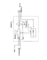
- FIG. 1 is a system configuration diagram for realizing an in-vehicle charging apparatus according to an embodiment of the present invention.
- an in-house facility 1 of a house 10 and an in-vehicle charging device 21 of a vehicle 2 are connected by a charging cable (power line) 4 via an earth leakage circuit breaker (EVSE) 3.
- EVSE earth leakage circuit breaker
- one end of the charging cable 4 is connected to the in-house facility 1 by a three-pole plug / outlet 5 made of, for example, a single-phase AC of 100 V AC and a ground wire.
- the other end of the charging cable 4 is connected to the in-vehicle charging device 21 of the vehicle 2 through a four-pole connection terminal including a CPLT line terminal in the three-pole vehicle side connection terminal, although not particularly illustrated. Yes.
- the earth leakage breaker 3 may be directly connected to the charging cable 4, but may be attached to a charging pole installed in advance. In any case, the plug / outlet 5 side of the charging cable 4 including the earth leakage breaker 3 is included in the infrastructure equipment.
- the home equipment 1 includes a distribution board 11, a house-side PLC terminal 12, an Internet modem 13, a television 14, and a personal computer 15.
- the distribution board 11 performs drawing of the power line from the outdoor utility pole and branching of the power line in the house 10.
- the house side PLC terminal 12 is connected to a power line branched from the distribution board 11 and controls the supply of charging power to the vehicle 2 side or establishes a PLC with the vehicle 2 side.
- the Internet modem 13 is connected to the house side PLC terminal 12 and transmits / receives an information signal (vehicle information) by the PLC.
- the television 14 and the personal computer 15 are connected to the Internet modem 13.
- the vehicle 2 is configured by an in-vehicle charging device 21 that receives charging power sent from the house-side PLC terminal 12 via the charging cable 4 and controls charging of the vehicle 2, a camera 22, an air conditioner 23, and the like. Yes.
- the vehicle-mounted charging device 21 is comprised by the storage battery 24, the charger 25, the vehicle side PLC communication control part 26, the memory
- illustration is abbreviate
- the above-described four-pole vehicle-side connection terminal for connecting the charging cable 4 to the in-vehicle charging device 21 is provided at a predetermined position of the body in the vehicle 2.
- This vehicle-side connection terminal is also illustrated. Is omitted.
- FIG. 2 is a detailed circuit configuration diagram of the leakage breaker 3 shown in FIG.
- the earth leakage circuit breaker 3 inputs two single-phase AC lines (AC1, AC2) and one ground line (GND) in the charging cable 4 on the in-home facility 1 side.
- Two single-phase alternating current lines (AC1, AC2) and one ground line (GND) are connected to the vehicle 2 via each contact point of the leakage breaker relay 31 of the leakage breaker 3 interposed between the wires (AC1, AC2).
- AC1, AC2 ground line
- the leakage breaker 3 further includes a leakage detection unit 32 that detects a change in the magnetic field when a leakage occurs on the power lines AC1 and AC2, and detects the leakage.
- a relay control unit 33 is provided that inputs the leakage detection signal detected by the unit 32 and the control signal Sg transmitted from the vehicle 2 and controls ON / OFF of the contact point of the leakage breaker relay 31.
- the relay control unit 33 turns off the contact point of the leakage breaker relay 31 when the leakage detection unit 32 detects leakage, regardless of the presence or absence of the control signal Sg from the vehicle 2 side. Further, when the leakage detection unit 32 detects leakage, when the control signal Sg transmitted from the vehicle 2 is an instruction to turn on the contact of the leakage breaker relay 31, the relay control unit 33 Control is performed to immediately turn off the contact of the earth leakage interrupting relay 31 after turning it on for a moment.
- the leakage detection unit 32 detects a leakage current, necessary vehicle information on the vehicle 2 side is transmitted to the in-home equipment 1 side in the momentary ON period of the leakage breaker relay 31, and after the vehicle information is transmitted By immediately turning off the earth leakage cutoff relay 31, the no-voltage state of the vehicle-side connection terminal of the charging cable 4 is maintained as long as possible to ensure electrical safety.
- FIG. 3 is a block diagram showing a detailed configuration of the in-vehicle charging device 21 shown in FIG.
- the in-vehicle charging device 21 includes a storage battery 24, a charger 25, a vehicle side PLC communication control unit 26, a storage unit 27, and a storage battery relay 28.
- the storage battery 24 supplies electric power for driving the electric motor (not shown) of the vehicle 2 shown in FIG.
- the charger 25 receives AC charging power sent from the home facility 1 shown in FIG. 1 through the charging cable 4 and converts it into DC to charge the storage battery 24.
- the vehicle-side PLC communication control unit 26 establishes a PLC when an information signal (vehicle information) on the vehicle 2 side is transmitted to the in-home facility 1 via the charging cable 4.
- the storage unit 27 stores various vehicle information on the vehicle 2 side.
- the storage battery relay 28 opens and closes the main circuit of the storage battery 24.
- the charger 25 receives a single-phase alternating current (AC1, AC2) power from the leakage circuit breaker 3 side shown in FIG. 2 and converts it into direct current power to charge the storage battery 24.
- the charging control unit 25b detects that the storage battery 24 and the charger power supply circuit 25a have completed preparation for charging and transmits a control signal Sg to the relay control unit 33 of the leakage breaker 3.
- the in-vehicle charging device 21 receives the single-phase AC lines (AC1, AC2) and the ground line (GND) of the charging cable 4.
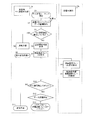
- FIG. 4 is a flowchart illustrating a flow in which the vehicle-side PLC communication control unit 26 of the in-vehicle charging device 21 performs the PLC processing in the first embodiment of the present invention. That is, in this flowchart, it is a process performed between the vehicle side PLC communication control unit 26 and the charge control unit 25b of the charger 25 in the in-vehicle charging device 21 shown in FIG. The flow of the process which transmits the vehicle information (data) of the vehicle 2 to the in-home equipment 1 by determining the initiative is shown.
- step S1 when a PLC transmission sequence for transmitting vehicle information of the vehicle 2 to the in-home facility 1 side using the charging cable 4 is started (step S1), the vehicle-side PLC communication control unit 26 stores the information. The transmission memory buffer capacity of the vehicle information stored in the unit 27 is detected (step S2). And the vehicle side PLC communication control part 26 determines whether the PLC communication connection (communication line) by the charging cable 4 is established between the vehicle 2 and the premises equipment 1 (house side PLC terminal 12). (Step S3).
- the vehicle-side PLC communication control unit 26 exchanges a regular PLC packet between the vehicle 2 and the in-home equipment 1 or detects the voltage of the AC line of the charging cable 4.
- the vehicle-side PLC communication control unit 26 sends vehicle information (data) of the vehicle 2 to the in-home equipment 1 while constantly detecting whether or not the communication connection between the vehicle 2 and the in-home equipment 1 is normal. Starts normal transmission (step S4).
- the vehicle side PLC communication control part 26 performs the normal transmission process of the regular packet by PLC, continuing the charge to the storage battery 24 (step S5).
- the vehicle-side PLC communication control unit 26 performs a transmission start determination process (step S3).
- the transmission start determination process is any condition (form) of the vehicle information of the vehicle 2 in order to establish the PLC communication connection by turning on the leakage breaker relay 31 of the leakage breaker 3 only when the vehicle information is transmitted. Is a process for determining whether to start transmission to the in-home facility 1.
- the vehicle information transmission start determination process is a process of determining the transmission start time point according to the condition (form) of the vehicle information.
- step S6 when the transmission start determination process is performed in step S6, the vehicle-side PLC communication control unit 26 turns on the leakage breaker relay 31 of the leakage breaker 3 shown in FIG.
- the charging control unit 25b is requested (step S7).
- the charging control unit 25b receives a request to turn on the leakage breaker relay 31 (step S8), and transmits the ON information on the leakage breaker relay 31 to the leakage breaker 3 as a control signal Sg via the control signal line.
- An ON request is made for the ground fault interrupt relay 31 (step S9).
- the vehicle-side PLC communication control unit 26 determines whether or not the PLC communication connection has been established (step S10). If the PLC communication connection cannot be established (NO in step S10), the charging cable is determined. It is determined that an error has occurred somewhere in 4 and transmission is impossible (step S11). On the other hand, if a PLC communication connection can be established in step S10 (YES in step S10), a process of transmitting vehicle information (data) of the vehicle 2 to the in-home equipment 1 is started (step S12), and predetermined vehicle information (data When the transmission of) is completed, the process proceeds to an OFF sequence (step B) of the leakage breaker relay 31 described later (step S13).
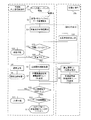
- FIG. 5 is a flowchart showing a flow in which the charge control unit 25b of the charger 25 performs the PLC processing in the second embodiment of the present invention. That is, in this flowchart, the process is performed between the vehicle-side PLC communication control unit 26 and the charging control unit 25b of the charger 25 in the in-vehicle charging device 21 shown in FIG. Shows the flow of processing for determining the initiative and transmitting the vehicle information (data) of the vehicle 2 to the in-house facility 1.
- step S1 when a PLC transmission sequence for transmitting the vehicle information of the vehicle 2 to the in-home facility 1 side using the charging cable 4 is started (step S1), the vehicle-side PLC communication control unit 26 Then, the transmission memory buffer capacity of the vehicle information stored in the storage unit 27 is detected (step S2).
- the vehicle-side PLC communication control unit 26 requests the charging control unit 25b to check whether or not the charger 25 of the vehicle charging device 21 is being charged (step S21). Then, the charging control unit 25b of the charger 25 makes a response of the charging execution status to the vehicle-side PLC communication control unit 26 (step S22).
- the vehicle-side PLC communication control unit 26 determines whether or not a leakage has occurred during the charging based on the detection information of the leakage detection unit 32 in the leakage breaker 3 (step S23). If leakage has occurred in charging cable 4 (YES in step S23), it is determined that vehicle information (data) cannot be transmitted (step S24), and the transmission process ends. In other words, when leakage occurs in the charging cable 4, the vehicle information (data) transmission process is immediately terminated without turning on the leakage interrupt relay 31.
- Step S25 the vehicle-side PLC communication control unit 26 determines whether charging is being performed using the charging cable 4.
- the vehicle-side PLC communication control unit 26 Normal transmission for sending vehicle information (data) to the in-house facility 1 is started (step S4), and normal transmission processing by PLC is executed (step S5).
- step S6 the vehicle information (data) of the vehicle 2 is set in any condition (data) in order to establish the PLC communication connection by turning on the leakage breaker relay 31 of the leakage breaker 3 only when the vehicle information is transmitted.
- This is a process for determining whether to start transmission to the in-house facility 1 in the form).
- the transmission start determination process is a process of determining the transmission start time point based on the condition (form) of the vehicle information (data).
- step S6 when vehicle information transmission start determination processing is performed in step S6, the vehicle-side PLC communication control unit 26 turns on the leakage breaker relay 31 of the leakage breaker 3 shown in FIG.
- the charge control unit 25b of the charger 25 is requested to perform PLC communication control by 25 (step S7).
- the charging control unit 25b receives a request to turn on the leakage breaker relay 31 (step S8), and transmits the ON information on the leakage breaker relay 31 to the leakage breaker 3 as a control signal Sg via the control signal line.
- An ON request is made for the ground fault interrupt relay 31 (step S9).
- the vehicle-side PLC communication control unit 26 determines whether or not the PLC communication connection has been established (step S10). If the PLC communication connection cannot be established (NO in step S10), the charging cable is determined. It is determined that an error has occurred somewhere in 4 and transmission is impossible (step S11). On the other hand, if the PLC communication connection can be established in step S10 (YES in step S10), the vehicle information (data) of the vehicle 2 starts to be transmitted to the in-house facility 1 (step S12), and the transmission of the vehicle information (data) is completed. If it does, it will transfer to the OFF sequence (B step) of the earth-leakage interruption
- the determination criteria for starting transmission of vehicle information include the following three determination criterion patterns (1) to (3).
- the vehicle information stored in the storage unit 27 of the in-vehicle charging device 21 is transmitted when the transmission memory buffer capacity is full.
- (2) Transmit when vehicle information with high priority is detected.
- (3) When the evaluation value determined by priority ⁇ data size (vehicle information size) exceeds a certain value, vehicle information is transmitted.
- the vehicle information stored in the storage unit 27 is transmitted in a batch based on any one of these three criterion patterns.
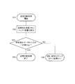
- FIG. 6 is a flowchart showing a flow of pattern 1 of the transmission start determination process in step S6 shown in FIG. 4 or 5 in the third embodiment of the present invention.
- the transmission start determination process of pattern 1 is a determination process for starting transmission by PLC when the transmission memory buffer capacity of the vehicle information accumulated in the storage unit 27 becomes full.
- step S ⁇ b> 31 when vehicle information transmission determination processing is started (step S ⁇ b> 31), the vehicle-side PLC communication control unit 26 of the in-vehicle charging device 21 transmits a vehicle information transmission memory buffer capacity already stored in the storage unit 27. Is calculated (step S32). Then, the vehicle-side PLC communication control unit 26 determines whether or not the data size of the transmission memory buffer capacity of the accumulated vehicle information is greater than or equal to a certain value (step S33).
- step S33 If the data size of the transmission memory buffer capacity is equal to or greater than a certain value (YES in step S33), the vehicle information transmission determination process is terminated (step S34), and the data size of the vehicle information transmission memory buffer capacity is When a certain value is reached, the PLC is established and data transmission is performed collectively.
- step S33 If the data size of the vehicle information transmission memory buffer stored in the storage unit 27 is not greater than or equal to a certain value in step S33 (NO in step S33), the process returns to step S2 in FIGS. 4 and 5 (step S35). ), The detection of the transmission memory buffer capacity of the vehicle information stored in the storage unit 27 is continued.
- the flow of the vehicle information transmission determination process shown in steps S31 to S34 described above means the following.
- charging is not performed, that is, when the leakage breaker relay 31 of the leakage breaker 3 is cut off and the PLC is not established, the leakage of the leakage breaker 3 when the vehicle information exceeds a certain amount
- the cut-off relay 31 is turned on, a communication connection by the PLC is temporarily established, and data is transmitted to the home-side PLC terminal 12 of the home equipment 1 in a lump.
- the vehicle side connection terminal of the charging cable 4 is brought into a non-voltage state to improve electrical safety. Secure.
- the vehicle information transmitted from the vehicle-mounted charging device 21 at this time can be monitored on the screen of the television 14 or the personal computer 15 of the in-home equipment 1.
- FIG. 7 is a flowchart showing a flow of pattern 2 of the transmission start determination process in step S6 shown in FIG. 4 or 5 in the third embodiment of the present invention.
- the transmission start determination process of pattern 2 is a determination process for determining the priority of the vehicle information in advance and transmitting the vehicle information having a high priority by the PLC.
- step S ⁇ b> 41 when vehicle information transmission determination processing is started (step S ⁇ b> 41), the vehicle-side PLC communication control unit 26 of the in-vehicle charging device 21 transmits a vehicle information transmission memory buffer capacity already stored in the storage unit 27. Is calculated (step S42). And the vehicle side PLC communication control part 26 determines whether the data size of the transmission memory buffer capacity
- step S44 based on the table A in which the priority for the category of the vehicle information, the priority coefficient, the data size example, and the evaluation value are compared, the new accumulation data of the vehicle information is stored.
- Check the priority For example, “failure detection information” in vehicle information has the highest priority at priority 5, and “travel history”, which is vehicle information that is periodically transmitted to the server, has the lowest priority at priority 1. Yes.
- correspond one by one is shown.
- step S44 the priority of the newly accumulated data of the vehicle information is confirmed based on the table A shown in FIG. 9, and there is vehicle information whose priority is not less than a specified value (for example, priority 4 or more). Whether or not (step S45).
- step S45 if it is detected that there is vehicle information with a priority equal to or higher than a specified value (for example, priority 4 or higher) (YES in step S45), the transmission determination process is terminated (step S46), and the PLC is established.
- the vehicle information stored in the transmission memory buffer is transmitted in a batch.
- the PLC is established and the vehicle information whose priority is a specified value or higher (for example, priority 4 or higher).
- vehicle information having a priority of 4 or more failure detection information, battery leakage detection information, user-driven communication request information, sensor camera screen (emergency), vehicle interior temperature abnormality information It is determined that there is charging rate decrease information, and only vehicle information with priority 4 or higher is immediately transmitted.
- step S45 If there is no vehicle information whose priority is a specified value or higher (eg, priority 4 or higher) in step S45 (NO in step S45), the process returns to step S2 in FIGS. 4 and 5 (step S47), and the storage unit 27 continues to detect the transmission memory buffer capacity of the vehicle information stored in the vehicle information.
- a specified value or higher eg, priority 4 or higher
- the flow of the vehicle information transmission determination process shown in steps S41 to S46 described above means the following.
- charging is not performed, that is, when the leakage breaker relay 31 of the leakage breaker 3 is cut off and the PLC is not established, the leakage breaker only when vehicle information having a priority level higher than a specified value exists. 3 is set to ON, communication connection by PLC is temporarily established, and only vehicle information data with a priority level equal to or higher than a specified value is transmitted to the home-side PLC terminal 12 of the in-house facility 1 in a lump. .
- the earth leakage breaker relay 31 of the earth leakage breaker 3 is turned off, the vehicle side connection terminal of the charging cable 4 is brought into a non-voltage state, and the electric Secure safety. Moreover, the vehicle information with high priority transmitted at this time can be monitored on the screen of the television 14 or the personal computer 15 of the in-home equipment 1.
- FIG. 8 is a flowchart showing a flow of pattern 3 of the transmission start determination process in step S6 shown in FIG. 4 or 5 in the third embodiment of the present invention.
- a priority coefficient is determined in advance for vehicle information, and determination for transmitting vehicle information whose evaluation value determined by priority coefficient ⁇ data size is equal to or greater than a specified value by the PLC is performed. It is processing.
- step S ⁇ b> 51 when vehicle information transmission determination processing is started (step S ⁇ b> 51), the vehicle-side PLC communication control unit 26 of the in-vehicle charging device 21 transmits a vehicle information transmission memory buffer capacity already stored in the storage unit 27. Is calculated (step S52). Then, the vehicle-side PLC communication control unit 26 determines whether or not the data size of the transmission memory buffer capacity of the vehicle information that has been accumulated in the storage unit 27 is greater than or equal to a certain value (step S53). If the data size of the transmission memory buffer capacity is greater than or equal to a certain value (YES in step S53), the transmission determination process is terminated (step S56).
- FIG. 9 is a diagram showing a table A in which priorities, priority coefficients, data size examples, and evaluation values for vehicle information are compared. That is, in the above-described step S54, as shown in the table A of FIG. 9, the priority coefficient predetermined for each vehicle information type (category) is multiplied by the data size to obtain the vehicle information type ( An evaluation value is calculated for each category. For example, as shown in Table A, when the vehicle information is sensor camera information (emergency), since the priority coefficient is 100 and the data size is 40000 bytes, the evaluation value is calculated as 4,000,000.
- step S55 it is determined whether or not the evaluation value of the vehicle information calculated in step S54 is not less than a specified value. If the evaluation value of the vehicle information is not less than the specified value. (YES in step S55), the transmission determination process is terminated (step S56), the PLC is established, and only vehicle information whose evaluation value is equal to or greater than a specified value is transmitted.
- a specified value For example, according to Table A shown in FIG. 9, it is determined that there is a sensor camera image (emergency) having an evaluation value of vehicle information equal to or greater than a specified value of 4,000,000, the transmission determination process is terminated, and the storage unit The vehicle information stored in 27 is transmitted collectively by PLC. Alternatively, only vehicle information whose vehicle information evaluation value is equal to or greater than a specified value may be transmitted.
- step S55 If there is no vehicle information whose evaluation value is greater than or equal to the prescribed value in step S55 (NO in step S55), the process returns to step S2 in FIGS. 4 and 5 (step S57), and the vehicle information accumulated in the storage unit 27. Continue to detect the send memory buffer capacity.
- the flow of the vehicle information transmission determination process shown in steps S51 to S56 described above means the following.
- the leakage breaker only when vehicle information having an evaluation value equal to or greater than a specified value exists. 3 is set to ON, communication connection by PLC is temporarily established, and only vehicle information data whose evaluation value is equal to or greater than a specified value is transmitted to the home-side PLC terminal 12 of the home equipment 1 at a time. .
- the leakage breaker relay 31 of the leakage breaker 3 is immediately turned off, and the vehicle-side connection terminal of the charging cable 4 is brought into a non-voltage state to electrically Secure safety.
- the vehicle information with a high evaluation value transmitted at this time can be monitored on the screen of the television 14 or the personal computer 15 of the in-house facility 1. For example, when a suspicious person approaches a vehicle parked in a garage at night, the sensor camera image (emergency) is immediately displayed on the screen of the TV 14 or the personal computer 15 and is used for preventing theft of the vehicle. Can do.
- the effect by using the evaluation value of vehicle information as a transmission judgment standard is as follows.
- the “sensor vibration detection information” of the vehicle information shown in the table A of FIG. 9 has a priority of 3 and a data size of 16 bytes. Therefore, when the priority 5 or the memory buffer capacity is 256 Kbytes as the condition for the transmission determination criterion, the data (16 bytes) of “sensor vibration detection information” is not satisfied unless it is detected 16,000 times or more. Therefore, the vehicle information transmission standard is not reached unless a considerable number of vibrations are detected. Therefore, for example, even if the vehicle is parked for charging on an unpaved rough road and a vibration is detected due to a large vehicle passing on the side, there is no possibility that “sensor vibration detection information” is frequently transmitted.
- the threshold value of the vehicle information evaluation value is set to 1,500.
- the evaluation value of “sensor vibration detection information” in the vehicle information is 1,600, and therefore, the first “sensor vibration detection information” satisfies the condition of the transmission determination criterion. Therefore, since the evaluation value of the vehicle information becomes a certain value or more, the PLC can be immediately established and the vehicle information of “sensor vibration detection information” can be transmitted.
- the “room temperature abnormality information” of the vehicle information shown in Table A of FIG. 9 is a phenomenon that can occur on a daily basis, so the priority coefficient is set low (priority coefficient 10 And the vehicle information evaluation value is kept as low as 160. Thereby, the effect of suppressing the transmission frequency of the vehicle information of “indoor temperature abnormality” can be expected.
- FIG. 10 is a diagram showing a table B in which the type command is compared with the type content of the vehicle information.
- Types of vehicle information include emergency information, maintenance information, warning information, user information, and periodic transmission information.
- emergency information includes vehicle vibration detection information, leakage detection information, sensor camera image (emergency) information. And related information.
- the vehicle information transmission judgment criteria pattern 4 is transmitted based on the grouped vehicle information type contents as shown in Table B of FIG. Judgment can also be made.
- the criteria for judging transmission are as follows. That is, (1) the superiority or inferiority of transmission is determined by a type command. For example, if the type command is “01” in Table B, the corresponding vehicle information is immediately transmitted. (2) If the type command is “02” or “03”, for example, vehicle information is transmitted after 10 minutes, if “04”, the vehicle information is transmitted immediately, and if “05”, the vehicle is transmitted one hour later. As in the case of transmitting information, the transmission timing is determined according to the situation at that time.
- FIG. 11 is a flowchart showing a flow of processing in which the vehicle-side PLC communication control unit 26 shifts the leakage interrupt relay 31 to the OFF sequence and terminates the PLC in the fourth embodiment of the present invention.
- Step S61 first, following the step S13 of FIGS. 4 and 5, when the OFF sequence of the leakage breaker relay 31 is started (step S61), a packet is transmitted from the memory buffer already stored in the storage unit 27 ( Step S62), it is determined whether or not the transmission of the packet is successful (Step S63). If the transmission of the packet is successful (YES in step S63), the transmitted data is deleted from the accumulated memory buffer to increase the free space in the storage unit 27 (step S64).
- the vehicle-side PLC communication control unit 26 determines whether or not the accumulated memory buffer in the storage unit 27 is empty (step S65). If the accumulated memory buffer in the storage unit 27 is empty (YES in step S65), the vehicle-side PLC communication control unit 26 determines whether data is currently being received (step). S66). If the vehicle-side PLC communication control unit 26 is currently receiving data (YES in step S66), the process for determining whether or not the accumulated memory buffer in step S65 is empty and the data in step S66 are used. The process of determining whether or not data is being received is repeated, and the process waits for completion of data reception (step S67).
- step S68 the data transmission process is terminated (step S68), and the leakage control relay 31 is sent to the charge control unit 25b. Is requested to transmit a control signal Sg for turning off (step S69).
- the charging control unit 25b receives the OFF request signal of the leakage breaker relay 31 (step S70), and requests the relay control unit 33 of the leakage breaker 3 to turn off the leakage breaker relay 31 (step S71).
- the leakage interrupt relay 31 is turned off and the PLC communication connection is disconnected (step S72), and the OFF sequence of the leakage interrupt relay 31 ends (step S73).
- step S74 it is determined whether or not the PLC communication connection is established (step S74), and if the PLC communication connection is established (step S74). YES in step S74), a packet retransmission process is performed (step S75), and the process of determining whether or not the packet transmission in step S63 described above has been successful is repeated. If the PLC communication connection is not established in step S74 (NO in step S74), all data in the memory buffer in the storage unit 27 is deleted (step S76), and the memory buffer is emptied and new update information is created. Can be stored, and the process proceeds to the transmission end step in step S68.
- FIG. 12 is a flowchart showing a flow of PLC connection at the start of charging that is generally performed.
- the charging start sequence is started (step S81)
- the charging cable 4 is connected to the in-home device 1 on the input side of the leakage breaker 3 (step S82).
- the relay control part 33 of the earth leakage breaker 3 confirms whether the constant voltage is supplied to the earth leakage breaker 3 from the household device 1 and whether the control signal line is in an energized state (step S83). .
- the charging control unit 25b of the in-vehicle charging device 21 detects that the charging cable 4 is connected to the in-vehicle charging device 21 side (step S84), and determines whether the preparation for charging is completed (step S85). ). Here, if the preparation for charging is not completed (NO in step S85), the process waits until the preparation for charging is completed. If the preparation for charging is completed (YES in step S85), the charging control unit 25b of the in-vehicle charging device 21 detects the electric leakage. A control signal Sg is transmitted to the relay control unit 33 of the circuit breaker 3 through the control signal line (step S86).
- the relay control unit 33 of the leakage breaker 3 detects the control signal Sg and turns on the leakage breaker relay 31 (step S87). Then, the charging power (AC power) from the in-home equipment 1 is supplied to the in-vehicle charging device 21 and the storage battery relay 28 is turned on by the charging control unit 25b, so that charging of the storage battery 24 is started (step S88). ). And the vehicle side PLC communication control part 26 establishes the communication connection by PLC between the vehicle-mounted charging device 21 and the house side PLC terminal 12 (step S89), and complete
- the in-vehicle charging device 21 when the earth leakage breaker 3 is opened and charging by the charging cable 4 is not performed, the following three patterns are used.
- the communication connection by PLC is established only for the necessary minimum time by any one of the above, and only necessary vehicle information is transmitted to the in-house facility 1, and immediately after the vehicle information transmission is completed, the PLC communication connection is interrupted, The electrical safety of the vehicle side connection terminals is ensured.
- vehicle information to be communicated by PLC is stored (buffered) in the storage unit 27, and when the stored data exceeds a certain value, it is transmitted collectively by PLC.
- Priorities are set for each type of vehicle information data, and if there is vehicle information that is higher than a predetermined priority level, the stored data is transmitted in a batch by PLC.
- the leakage interrupt relay 31 of the leakage breaker 3 is turned off to disconnect the PLC communication connection (communication line).
- the leakage cutoff relay 31 of the leakage breaker 3 is turned on for the minimum necessary time to establish a PLC communication line, and the stored data can be transmitted in a batch. it can.
- the no-voltage state of the vehicle-side connection terminal of the charging cable 4 can be lengthened as much as possible, the electrical safety can be maintained at a relatively high level.
- the vehicle-side PLC communication control unit 26 always inquires of the charging control unit 25b whether or not charging is in progress, and if charging is in progress, starts communication by normal PLC and transmits vehicle information. In addition, when charging is not in progress, either when the vehicle information exceeds a predetermined data size, when there is vehicle information with a high priority, or when there is vehicle information with a high evaluation value Perform batch transmission. Note that if the vehicle-side PLC communication control unit 26 detects whether or not charging is currently being performed, it is not necessary to determine again whether or not a PLC communication line has been established.
- the capacity of the storage unit 27 can be effectively used to the maximum extent by deleting the vehicle information that has been transmitted from the storage unit 27. Further, when the transmission of the vehicle information cannot be completed and the communication line by the PLC is not established, the vehicle information lower than the predetermined priority is deleted. Thereby, even if transmission of vehicle information is not completed, when a communication line by PLC cannot be established, vehicle information with low priority can be deleted, and a free area in the storage unit 27 can be effectively secured.
- the vehicle-side PLC communication control unit 26 does not issue a command to turn on the leakage interrupt relay 31 to the charging control unit 25b when receiving information on leakage from the leakage breaker 3. That is, when a leakage occurs in the charging cable (power line) 4 and the leakage breaker relay 31 is turned off, a control signal Sg for turning on the leakage breaker relay 31 is transmitted to cause the leakage breaker relay 31 to instantaneously However, it is possible to prevent a problem that turns ON.
- the present invention has been specifically described based on several embodiments, the present invention is not limited to the above-described embodiments, and various modifications can be made without departing from the scope of the present invention. It is.
- the communication line establishment condition by the PLC while charging is stopped is not limited to the above three pattern conditions, but may be changed to a desired condition according to the user's desire.
- the description has been made on the assumption that an in-vehicle charging device mounted on an EV or HEV that can be charged from the outside, but the present invention is not limited to this, and a storage battery mounted on a normal gasoline vehicle. Needless to say, the present invention can also be applied to an in-vehicle charging apparatus for charging a battery.
- the present invention can be used as an in-vehicle charging device for HEVs and EVs, but can also be effectively used as an in-vehicle charging device for general vehicles such as gasoline vehicles.
Landscapes
- Engineering & Computer Science (AREA)
- Power Engineering (AREA)
- Transportation (AREA)
- Mechanical Engineering (AREA)
- Sustainable Energy (AREA)
- Sustainable Development (AREA)
- Life Sciences & Earth Sciences (AREA)
- General Chemical & Material Sciences (AREA)
- Electrochemistry (AREA)
- Chemical Kinetics & Catalysis (AREA)
- Chemical & Material Sciences (AREA)
- Manufacturing & Machinery (AREA)
- Charge And Discharge Circuits For Batteries Or The Like (AREA)
- Remote Monitoring And Control Of Power-Distribution Networks (AREA)
- Secondary Cells (AREA)
- Electric Propulsion And Braking For Vehicles (AREA)
Abstract
充電休止中であってもPLCによって車両情報を送信することができ、かつ電力線の車両側接続端子を無電圧状態にすることができる車載充電装置。この装置では、車両に関する車両情報を蓄積する記憶部(27)と、記憶部(27)に蓄積された車両情報を車両の外部へ送信することが必要であると判断したとき、漏電遮断器(非図示)を閉路するための制御信号を送信するように指令する車両側PLC通信制御部(26)と、車両側PLC通信制御部(26)からの指令に基づいて制御信号を漏電遮断器へ送信する充電制御部(25b)とを備える。電気エネルギが蓄電池(24)に供給されていないとき、車両側PLC通信制御部(26)が、充電制御部(25b)から送信された制御信号によって漏電遮断器が閉路されたときにPLCを確立して車両情報を一括送信する。
Description
本発明は、車両に搭載され、外部電源から漏電遮断器を経由した電力線を介して車両に搭載した蓄電池を充電するための電力を供給する車載充電装置に関し、特に、前記電力線を通信回線として利用することができる車載充電装置に関する。
近年、HEV(Hybrid Electric Vehicle:ハイブリッド自動車)やEV(Electric Vehicle:電気自動車)が汎用化されつつあり、それに伴って、これらの車両に搭載された蓄電池を充電するための充電設備が広く利用されている。そこで、関連技術として、車両に搭載された蓄電池の充電制御を行うために、CPLT線(Control PiLoT線:通信制御線)を使用して充電ケーブル(電力線)のメインリレーをON/OFFする技術が開示されている(例えば、特許文献1参照)。この技術によれば、車両の外部電源からCPLT線を介して得られた電力情報に基づいて、電力料金の安い時間帯に充電ケーブルのメインリレーをONにすることにより、充電にかかるコストを安価に抑えながら車両の蓄電池に適正な充電を行うことができる。なお、CPLT線を利用した充電処理フローは、EVやHEVのジョイントコネクト規格であるISO/IEC61851規格や.SAE J1772規格で規定されているが、ここではその説明については省略する。
また、他の関連技術として、電力線を通信回線として利用するPLC(Power Line Communication:電力線通信)によって、車両に搭載された蓄電池の充電状態を監視する技術が開示されている(例えば、特許文献2参照)。この技術によれば、車両に搭載された蓄電池を充電する前に、車両IDを用いて電力線による通信回線すなわちPLCを確立しておく。そして、充電中に充電ケーブル(電力線)の外れなどが発生すると、充電中の充電ケーブルの外れを示すケーブル外れ検出信号、車両の状態を示す監視情報、及び車両IDを、充電ケーブルによる通信(PLC)によって、車両の充電制御装置から外部の充電ステーションへ送信する。これによって、1つの充電ステーションで複数の車両が充電している環境下において、充電中に充電ケーブル(電力線)の外れが発生した場合は、どの車両にどのような状態で充電ケーブルの外れが発生したかを、充電ステーション側で即座に監視・判別することができる。このようにして、車両と宅内設備(充電ステーション)との間のインフラ設備(つまり、電力線)に情報信号を重畳して送信するPLCを用いて通信回線を確立することにより、車両に搭載された蓄電池を適正に監視しながら充電制御することができる。
しかしながら、前記特許文献1の技術によると、車両に搭載された蓄電池が満充電になると、CPLT線を流れる制御信号によって、EVSE(Electric Vehicle Supply Equipment:外部電源と車両とを連結する機器(すなわち、給電側の漏電遮断器)のメイン回路のリレー接点が開放される。したがって、インフラ側(給電側)から車両側へ供給される電力線(充電ケーブル)の車両側接続端子が無電圧状態となるので、電力線の車両側接続端子が車両から取り外されても電気的には安全である。ところが、給電側と車両側とを結ぶ電力線が、EVSEのメイン回路のリレー接点によって物理的に遮断されている状態になるので、電力線の車両側接続端子が車両に接続されていても、車両に搭載された車載充電装置と外部電源(宅内設備)との間でPLCによる通信を行うことができない。すなわち、車両側から車両情報を送信することができない。
また、前記特許文献2の技術においては、車両に搭載された蓄電池への充電が完了すると、車両側の車載充電装置と外部の充電ステーションとの間に設けられた漏電遮断器のリレー接点が開放されるために、車載充電装置と外部の充電ステーションとの間の電力線(充電ケーブル)が物理的に遮断されてしまう。そのため、車両側から車両情報を送信することができない。
本発明の目的は、漏電遮断器がオフしているときでも、電力線通信によって車両側から車両情報を送信することができる車載充電装置を提供することである。
上記目的を達成するために、本発明に係る車載充電装置は、車両の外部にある電源から漏電遮断器を経由した電力線を介して前記車両に搭載した蓄電池を充電する車載充電装置であって、前記車両に関する車両情報を蓄積する記憶部と、前記記憶部に蓄積された前記車両情報を前記車両の外部へ送信することが必要であると判断したとき、前記漏電遮断器を閉路するための制御信号を出力した後、前記電力線を通信回線として用いてPLC通信の回線確立を行ない、前記記憶部に蓄積された前記車両情報を前記車両の外部への送信する前記車両側PLC通信制御部と、を備える構成を採る。
本発明によれば、電力線に接続された漏電遮断器が開路されて電気エネルギが蓄電池に供給されていないとき、すなわち、蓄電池への充電が行われていないときは、必要なタイミングだけ漏電遮断器を閉路してPLCの通信回線を確立させ、車載充電装置の記憶部に蓄積された車両情報を外部へ送信している。これによって、蓄電池への充電が行われていないときは、PLCの通信回線によって車両情報を瞬時に送信しているとき以外の時間帯は漏電遮断器が開路されているため、電力線の車両側接続端子は無電圧状態になるので電気的な安全性が確保される。なお、車両情報を送信するタイミングの条件は、所定のデータサイズ以上の車両情報を一括送信する、優先度の高い車両情報を検知した場合に一括送信する、または、優先度係数×データサイズで求められる評価値が一定値以上となった場合に一括送信する、の何れかである。
本発明の実施の形態に係る車載充電装置は、外部電源(宅内設備)と車載充電装置とを接続する電力線(充電ケーブル)に介在されたEVSE(漏電遮断器)のメイン回路のリレー接点のON回数を可能な限り減らし、かつON時間を短く抑える。これにより、EVSEのメイン回路のリレー接点をOFFにする時間を長くすることができるので、電力線の車両側接続端子の電気的な安全性を確保することが可能となる。言い換えると、外部電源から車載充電装置へ充電電力(電気エネルギ)を供給する電力線の接続を必要とする時間、及び、充電電力の停止中において外部電源と車載充電装置との間でPLCによって情報信号(車両情報)を送受信する時間帯のみ、EVSEのメイン回路のリレー接点をONにする。これにより、電力線の車両側接続端子の電気的な安全性を確保することができる。
すなわち、車載用蓄電池への充電予約中や充電が完了してEVSEのメイン回路のリレー接点がOFFしているときは、車載充電装置側から外部電源を備える宅内設備側へ情報信号を送信したい内容によって、以下のいずれかが判断される。すなわち、今すぐEVSEのメイン回路のリレー接点をONにしてPLCによって情報信号を車載充電装置から宅内設備側へ送信するか、または、車載充電装置側に一定量のデータがたまってからリレー接点をONにして、PLCによって情報信号を車載充電装置から宅内設備側へ送信するか、が判断される。これによって、EVSEのメイン回路のリレー接点のON回数及びON時間を最小限にすることができるので、電力線の車両側接続端子の電気的な安全性を確保することが可能となる。
以下、図面を参照しながら、本発明に係る車載充電装置について幾つかの実施の形態を詳細に説明する。なお、以下の各実施の形態を説明するための全図において、同一要素は原則として同一の符号を付し、その繰り返しの説明は可能なかぎり省略する。
(実施の形態1)
図1は、本発明の一実施の形態に係る車載充電装置を実現するためのシステム構成図である。図1に示すように、家屋10の宅内設備1と車両2の車載充電装置21とが、漏電遮断器(EVSE)3を介して、充電ケーブル(電力線)4によって接続されている。なお、充電ケーブル4の一端は、例えばAC100Vの単相交流とアース線とによる3極のプラグ/コンセント5によって宅内設備1に接続されている。また、充電ケーブル4の他端は、特に図示されていないが、3極の車両側接続端子にCPLT線端子を含めた4極の接続端子を介して車両2の車載充電装置21に接続されている。
図1は、本発明の一実施の形態に係る車載充電装置を実現するためのシステム構成図である。図1に示すように、家屋10の宅内設備1と車両2の車載充電装置21とが、漏電遮断器(EVSE)3を介して、充電ケーブル(電力線)4によって接続されている。なお、充電ケーブル4の一端は、例えばAC100Vの単相交流とアース線とによる3極のプラグ/コンセント5によって宅内設備1に接続されている。また、充電ケーブル4の他端は、特に図示されていないが、3極の車両側接続端子にCPLT線端子を含めた4極の接続端子を介して車両2の車載充電装置21に接続されている。
また、漏電遮断器3は、充電ケーブル4にダイレクトに接続されている場合もあるが、あらかじめ設置されている充電ポールに付設されている場合もある。いずれの場合も、漏電遮断器3を含めた充電ケーブル4のプラグ/コンセント5側はインフラ設備に含まれる。
宅内設備1は、分電盤11、家屋側PLC端末12、インターネットモデム13、テレビ14及びパソコン15を備えて構成されている。分電盤11は、屋外電柱からの電力線の引き込みと家屋10内における電力線の分岐とを行う。家屋側PLC端末12は、分電盤11から分岐された電力線に接続され、車両2側へ充電用電力の供給を制御したり車両2側との間でPLCを確立したりする。インターネットモデム13は、家屋側PLC端末12に接続されてPLCによる情報信号(車両情報)の送受信を行う。テレビ14及びパソコン15は、インターネットモデム13に接続されている。
車両2は、家屋側PLC端末12から充電ケーブル4を介して送られてきた充電用電力を受電して車両2の充電制御を行う車載充電装置21と、カメラ22及びエアコン23などによって構成されている。また、車載充電装置21は、蓄電池24、充電器25、車両側PLC通信制御部26、及び記憶部27などによって構成されているが、これらの要素の詳細な説明は後述する。なお、車両2の通常の走行駆動装置などに関しては、本発明とは直接的には関係ないので図示が省略されている。また、車両2におけるボディの所定位置には、充電ケーブル4を車載充電装置21に接続するための先に述べた4極の車両側接続端子が設けられているが、この車両側接続端子も図示が省略されている。
図2は、図1に示す漏電遮断器3の詳細な回路構成図である。図2に示すように、漏電遮断器3は、宅内設備1側の充電ケーブル4における単相交流の2線(AC1、AC2)とグランドの1線(GND)を入力し、単相交流の2線(AC1、AC2)に介在された漏電遮断器3の漏電遮断リレー31の各接点を介して、単相交流の2線(AC1、AC2)とグランドの1線(GND)とが車両2側に入力されている。このような構成は、一般的に使用されている漏電遮断器と同じであるので、さらなる詳細な説明は省略する。
本発明の実施の形態においては、漏電遮断器3は、さらに、電力線AC1,AC2上に漏電が発生するとコイルの磁界が変化し、この磁界の変化を検出する漏電検出部32と、この漏電検出部32が検知した漏電検知信号と車両2から送信されてきた制御信号Sgとを入力して、漏電遮断リレー31の接点のON/OFFを制御するリレー制御部33とを備えている。
リレー制御部33は、漏電検出部32が漏電を検知したときには、車両2側からの制御信号Sgの有無如何に関わらず漏電遮断リレー31の接点をOFFにする。また、漏電検出部32が漏電を検知しているときに、車両2側から送信されてきた制御信号Sgが漏電遮断リレー31の接点をONにする指示であるときは、リレー制御部33は、漏電遮断リレー31の接点を一瞬ONにした後に直ちにOFFにする制御を行う。すなわち、漏電検出部32が漏洩電流を検知したときは、漏電遮断リレー31の一瞬のON期間において車両2側の必要な車両情報を宅内設備1側へ送信し、車両情報が送信された後は、直ちに漏電遮断リレー31をOFFにすることにより、充電ケーブル4の車両側接続端子の無電圧状態を可能な限り長く維持して、電気的な安全性を確保している。
図3は、図1に示す車載充電装置21の詳細な構成を示すブロック図である。図3に示すように、車載充電装置21は、蓄電池24、充電器25、車両側PLC通信制御部26、記憶部27、および蓄電池用リレー28を備えて構成されている。蓄電池24は、図1に示す車両2の電動機(図示せず)を駆動するための電力を供給する。充電器25は、図1に示す宅内設備1から充電ケーブル4を通して送られてきた交流の充電用電力を受電して直流に変換して蓄電池24を充電する。車両側PLC通信制御部26は、充電ケーブル4を介して車両2側の情報信号(車両情報)を宅内設備1へ送信するときにPLCを確立させる。記憶部27は、車両2側の各種車両情報を記憶する。蓄電池用リレー28は、蓄電池24のメイン回路を開閉する。
また、充電器25は、図2に示す漏電遮断器3側から単相交流(AC1、AC2)の電力を受電し、これを直流電力に変換して蓄電池24を充電する充電器電源回路25aと、蓄電池24や充電器電源回路25aが充電準備を完了したことを検知して制御信号Sgを漏電遮断器3のリレー制御部33へ送信する充電制御部25bとによって構成されている。なお、車載充電装置21には、充電ケーブル4の単相交流線(AC1、AC2)とグランド線(GND)とが入力されている。
次に、本発明の実施の形態1に係る車載充電装置の動作について、フローチャートを参照しながら説明する。先ず、車載充電装置21の車両側PLC通信制御部26が主導判断してPLCの処理を行う場合の流れを説明する。図4は、本発明の実施の形態1において、車載充電装置21の車両側PLC通信制御部26が主導判断してPLCの処理を行う流れを示すフローチャートである。すなわち、このフローチャートでは、図3に示す車載充電装置21における車両側PLC通信制御部26と充電器25の充電制御部25bとの間で行われる処理であって、車両側PLC通信制御部26が主導判断して車両2の車両情報(データ)を宅内設備1へ送信する処理の流れを示している。
図4において、先ず、充電ケーブル4を使って車両2の車両情報を宅内設備1側へ送信するためのPLC送信シーケンスが開始されると(ステップS1)、車両側PLC通信制御部26は、記憶部27に蓄積されている車両情報の送信メモリバッファ容量を検知する(ステップS2)。そして、車両側PLC通信制御部26は、車両2と宅内設備1(家屋側PLC端末12)との間で充電ケーブル4によるPLCの通信接続(通信回線)が確立されているか否かを判定する(ステップS3)。
ここで、車両2と宅内設備1との間でPLCの通信接続が確立されていれば(ステップS3でYES)、通常の充電状態である。よって、車両側PLC通信制御部26は、例えば、車両2と宅内設備1との間でPLCの定期パケットを交換したり、充電ケーブル4のACラインの電圧を検知したりする。これにより、車両側PLC通信制御部26は、車両2と宅内設備1との通信接続が正常であるか否かを絶えず検知しながら、車両2の車両情報(データ)を宅内設備1へ送るための通常の送信を開始する(ステップS4)。そして、車両側PLC通信制御部26は、蓄電池24への充電を継続しながら、PLCによる定期パケットの通常送信処理を実行する(スッテップS5)。
一方、ステップS3で、車両2と宅内設備1との間でPLCの通信接続が確立されていなければ(ステップS3でNO)、車両側PLC通信制御部26は、送信開始判断処理を行う(ステップS6)。送信開始判断処理とは、車両情報を送信するときのみ漏電遮断器3の漏電遮断リレー31をONにしてPLCの通信接続を確立させるために、車両2の車両情報をどのような条件(形態)で宅内設備1へ送信開始するかを決定する処理である。なお、車両情報の送信開始判断処理は、車両情報の条件(形態)によって送信開始時点を判断する処理である。この処理の例としては、車載充電装置21の記憶部27に蓄積された車両情報の送信メモリバッファ容量が一杯になったら送信する、優先度の高い車両情報を送信する、または、優先度×データサイズで決定される評価値が大きい車両情報を送信する、などが挙げられる。このような送信開始判断処理の詳細な説明は後述する。
再び図4に戻って、ステップS6で送信開始判断処理が行われると、車両側PLC通信制御部26は、図2に示す漏電遮断器3の漏電遮断リレー31をONするように、充電器25の充電制御部25bに対して要求する(ステップS7)。すると、充電制御部25bが、漏電遮断リレー31のONの要求を受付け(ステップS8)、制御信号線を介して、漏電遮断リレー31のON情報を制御信号Sgとして漏電遮断器3へ送信し、漏電遮断リレー31のON要求を行う(ステップS9)。
これによって、車両側PLC通信制御部26は、PLCの通信接続が確立できたか否かを判断し(ステップS10)、もし、PLCの通信接続が確立できなければ(ステップS10でNO)、充電ケーブル4のどこかで異常が生じていて送信不能と判断する(ステップS11)。一方、ステップS10で、PLCの通信接続が確立できれば(ステップS10でYES)、車両2の車両情報(データ)を宅内設備1へ送信する処理を開始し(ステップS12)、所定の車両情報(データ)の送信が終了したら、後述する漏電遮断リレー31のOFFシーケンス(Bステップ)へ移行する(ステップS13)。
(実施の形態2)
次に、本発明の実施の形態2に係る車載充電装置の動作についてフローチャートを参照しながら説明する。実施の形態2では、充電器25の充電制御部25bが主導判断してPLCの処理を行う場合の流れについて説明する。図5は、本発明の実施の形態2において、充電器25の充電制御部25bが主導判断してPLCの処理を行う流れを示すフローチャートである。すなわち、このフローチャートでは、図3に示す車載充電装置21における車両側PLC通信制御部26と充電器25の充電制御部25bとの間で行われる処理であって、充電器25の充電制御部25bが主導判断して車両2の車両情報(データ)を宅内設備1へ送信する処理の流れを示している。
次に、本発明の実施の形態2に係る車載充電装置の動作についてフローチャートを参照しながら説明する。実施の形態2では、充電器25の充電制御部25bが主導判断してPLCの処理を行う場合の流れについて説明する。図5は、本発明の実施の形態2において、充電器25の充電制御部25bが主導判断してPLCの処理を行う流れを示すフローチャートである。すなわち、このフローチャートでは、図3に示す車載充電装置21における車両側PLC通信制御部26と充電器25の充電制御部25bとの間で行われる処理であって、充電器25の充電制御部25bが主導判断して車両2の車両情報(データ)を宅内設備1へ送信する処理の流れを示している。
なお、図5のフローチャートでは、図4のフローチャートと同一のステップは同じ符合番号を付し、破線で囲った部分の異なるステップについては新たな符合番号を付している。ここで、図5のフローチャートの流れを説明するに当たって、図4と異なるステップ(破線で囲った部分のステップ)のみを説明すると、処理全体の流れが理解し難いので、図4とステップが重複する部分についても処理の流れに従って順次説明する。
図5において、先ず、充電ケーブル4を使って車両2の車両情報を宅内設備1側へ送信するための、PLCの送信シーケンスが開始されると(ステップS1)、車両側PLC通信制御部26は、記憶部27に蓄積されている車両情報の送信メモリバッファ容量を検知する(ステップS2)。
次に、車両側PLC通信制御部26は、車両充電装置21の充電器25が充電実行中であるか否かの確認要求を、充電制御部25bに対して行う(ステップS21)。すると、充電器25の充電制御部25bは、車両側PLC通信制御部26に対して充電実施状況の応答を行う(ステップS22)。
これによって、車両側PLC通信制御部26は、漏電遮断器3における漏電検出部32の検出情報に基づいて、充電実施中に漏電が発生しているか否かの判定を行う(ステップS23)。ここで、充電ケーブル4に漏電が発生していれば(ステップS23でYES)、車両情報(データ)の送信は不能であると判断して(ステップS24)、送信処理を終了する。すなわち、充電ケーブル4に漏電が発生しているときは、漏電遮断リレー31をONすることなく、直ちに車両情報(データ)の送信処理を終了する。
一方、ステップS23で、充電ケーブル4に漏電が発生していなければ(ステップS23でNO)、車両側PLC通信制御部26は、充電ケーブル4を使って充電中であるか否かの判定を行う(ステップS25)。ここで、現在充電中であれば(ステップS25でYES)、車両2と宅内設備1との間でPLCの通信接続が既に確立されているので、車両側PLC通信制御部26は、車両2の車両情報(データ)を宅内設備1へ送るための通常送信を開始し(ステップS4)、PLCによる通常送信処理を実行する(ステップS5)。
一方、ステップS25で、現在充電中でなければ(ステップS25でNO)、車両2と宅内設備1との間でPLCの通信接続が確立されていないので、車両側PLC通信制御部26は、送信開始判断処理を行う(ステップS6)。送信開始判断処理は、車両情報を送信するときのみ漏電遮断器3の漏電遮断リレー31をONにしてPLCの通信接続を確立させるために、車両2の車両情報(データ)をどのような条件(形態)で宅内設備1へ送信開始するかを決定する処理である。なお、送信開始判断処理は、車両情報(データ)の条件(形態)によって送信開始時点を判断する処理である。この処理の例としては、車載充電装置21の記憶部27に蓄積された車両情報の送信メモリバッファ容量が一杯になったら送信する、優先度の高い車両情報を送信する、または、優先度×データサイズで決定される評価値が大きい車両情報を送信する、などが挙げられる。このような送信開始判断処理の詳細な説明は後述する。
再び図5に戻って、ステップS6で車両情報の送信開始判断処理が行われると、車両側PLC通信制御部26は、図2に示す漏電遮断器3の漏電遮断リレー31をONして充電器25によるPLCの通信制御を行うように、充電器25の充電制御部25bに対して要求する(ステップS7)。すると、充電制御部25bが、漏電遮断リレー31のONの要求を受付け(ステップS8)、制御信号線を介して、漏電遮断リレー31のON情報を制御信号Sgとして漏電遮断器3へ送信し、漏電遮断リレー31のON要求を行う(ステップS9)。
これによって、車両側PLC通信制御部26は、PLCの通信接続が確立できたか否かを判断し(ステップS10)、もし、PLCの通信接続が確立できなければ(ステップS10でNO)、充電ケーブル4のどこかで異常が生じていて送信不能と判断する(ステップS11)。一方、ステップS10で、PLCの通信接続が確立できれば(ステップS10でYES)、車両2の車両情報(データ)を宅内設備1へ送信開始し(ステップS12)、車両情報(データ)の送信が終了したら、後述する漏電遮断リレー31のOFFシーケンス(Bステップ)へ移行する(ステップS13)。
(実施の形態3)
次に、本発明の実施の形態3として、図4及び図5のステップS6における車両情報の送信開始判断処理について幾つかのパターンを詳細に説明する。すなわち、車両情報の送信開始の判断基準は、次の(1)~(3)の3つの判断基準パターンがある。(1)車載充電装置21の記憶部27に蓄積された車両情報の送信メモリバッファ容量が一杯になったら送信する。(2)優先度の高い車両情報を検知したら送信する。(3)優先度×データサイズ(車両情報サイズ)で決定される評価値が一定値を超えたら車両情報を送信する。これら3つの判断基準パターンの中の何れかの判断基準パターンに基づいて、記憶部27に蓄積された車両情報は一括して送信される。
次に、本発明の実施の形態3として、図4及び図5のステップS6における車両情報の送信開始判断処理について幾つかのパターンを詳細に説明する。すなわち、車両情報の送信開始の判断基準は、次の(1)~(3)の3つの判断基準パターンがある。(1)車載充電装置21の記憶部27に蓄積された車両情報の送信メモリバッファ容量が一杯になったら送信する。(2)優先度の高い車両情報を検知したら送信する。(3)優先度×データサイズ(車両情報サイズ)で決定される評価値が一定値を超えたら車両情報を送信する。これら3つの判断基準パターンの中の何れかの判断基準パターンに基づいて、記憶部27に蓄積された車両情報は一括して送信される。
図6は、本発明の実施の形態3において、図4または図5に示すステップS6における送信開始判断処理のパターン1の流れを示すフローチャートである。なお、パターン1の送信開始判断処理は、記憶部27に蓄積された車両情報の送信メモリバッファ容量が一杯になったらPLCによる送信を開始するための判断処理である。
図6において、先ず、車両情報の送信判断処理が開始されると(ステップS31)、車載充電装置21の車両側PLC通信制御部26は、記憶部27に蓄積済みの車両情報の送信メモリバッファ容量を算出する(ステップS32)。そして、車両側PLC通信制御部26は、蓄積済みである車両情報の送信メモリバッファ容量のデータサイズが一定値以上であるか否かを判定する(ステップS33)。ここで、送信メモリバッファ容量のデータサイズが一定値以上であれば(ステップS33でYES)、車両情報の送信判断処理を終了して(ステップS34)、車両情報の送信メモリバッファ容量のデータサイズが一定値以上にたった時点でPLCを確立させて一括してデータ送信を行う。
なお、ステップS33で、記憶部27に蓄積されている車両情報の送信メモリバッファのデータサイズが一定値以上でなければ(ステップS33でNO)、図4、図5のステップS2に戻り(ステップS35)、記憶部27に蓄積されている車両情報の送信メモリバッファ容量の検知を継続して続ける。
すなわち、前述のステップS31からS34に示す車両情報の送信判断処理の流れは、次のことを意味している。充電が行われていないとき、すなわち、漏電遮断器3の漏電遮断リレー31が遮断されていてPLCが確立していないときは、車両情報が一定量以上になったときに漏電遮断器3の漏電遮断リレー31をONにし、PLCによる通信接続を一時的に確立してデータを一括して宅内設備1の家屋側PLC端末12へ送信する。そして、データを一括して瞬時に送信した後は、直ちに、漏電遮断器3の漏電遮断リレー31をOFFにして、充電ケーブル4の車両側接続端子を無電圧状態にして電気的な安全性を確保する。また、このとき車載充電装置21から送信されてきた車両情報は、宅内設備1のテレビ14やパソコン15の画面によって監視することができる。
図7は、本発明の実施の形態3において、図4または図5に示すステップS6における送信開始判断処理のパターン2の流れを示すフローチャートである。なお、パターン2の送信開始判断処理は、あらかじめ車両情報に優先度を決めておき、優先度の高い車両情報をPLCによって送信するための判断処理である。
図7において、先ず、車両情報の送信判断処理が開始されると(ステップS41)、車載充電装置21の車両側PLC通信制御部26は、記憶部27に蓄積済みの車両情報の送信メモリバッファ容量を算出する(ステップS42)。そして、車両側PLC通信制御部26は、蓄積済みである車両情報の送信メモリバッファ容量のデータサイズが一定値以上であるか否かを判定する(ステップS43)。ここで、送信メモリバッファ容量のデータサイズが一定値以上であれば(ステップS43でYES)、送信判断処理を終了する(ステップS46)。一方、送信メモリバッファ容量のデータサイズが一定値以上でなければ(ステップS43でNO)、新たな車両情報が記憶部27へ蓄積されるときの新規蓄積データの優先度を確認する(ステップS44)。
すなわち、ステップS44においては、図9に示すような、車両情報のカテゴリに対する優先度、優先度係数、データサイズ例、及び評価値を対比させたテーブルAに基づいて、車両情報の新規蓄積データの優先度を確認する。例えば、車両情報の『故障検知情報』などは優先度5で最も優先度が高く、サーバへ定期的に送信する車両情報である『走行履歴』などは優先度1で最も優先度が低くなっている。なお、図9のテーブルAでは、コマンドと車両情報とが1対1で対応する場合のテーブルを示している。
このようにして、ステップS44において、図9に示すテーブルAに基づいて車両情報の新規蓄積データの優先度を確認し、優先度が規定値以上(例えば、優先度4以上)の車両情報があるか否かを判定する(ステップS45)。ここで、優先度が規定値以上(例えば、優先度4以上)の車両情報があることを検知した場合は(ステップS45でYES)、送信判断処理を終了し(ステップS46)、PLCを確立して送信メモリバッファに蓄積されている車両情報を一括して送信する。もしくは、優先度が規定値以上(例えば、優先度4以上)の車両情報があることを検知した場合は、PLCを確立して優先度が規定値以上(例えば、優先度4以上)の車両情報のみを送信するとしてもよい。例えば、図9に示すテーブルAにしたがえば、優先度が4以上の車両情報として、故障検知情報、電池漏電検知情報、ユーザ主導通信要求情報、センサカメラ画面(緊急)、車室内温度異常情報、及び充電率低下情報が存在すると判定し、これらの優先度4以上の車両情報のみを直ちに送信する。
なお、ステップS45で、優先度が規定値以上(例えば、優先度4以上)の車両情報がなければ(ステップS45でNO)、図4、図5のステップS2に戻り(ステップS47)、記憶部27に蓄積されている車両情報の送信メモリバッファ容量の検知を継続して続ける。
すなわち、前述のステップS41からS46に示す車両情報の送信判断処理の流れは、次のことを意味している。充電が行われていないとき、すなわち、漏電遮断器3の漏電遮断リレー31が遮断されていてPLCが確立していないときは、優先度が規定値以上の車両情報が存在するときのみ漏電遮断器3の漏電遮断リレー31をONにし、PLCによる通信接続を一時的に確立して、優先度が規定値以上の車両情報のデータのみを一括して宅内設備1の家屋側PLC端末12へ送信する。そして、優先度の高いデータを一括して瞬時に送信した後は、直ちに、漏電遮断器3の漏電遮断リレー31をOFFにして、充電ケーブル4の車両側接続端子を無電圧状態にして電気的な安全性を確保する。また、このとき送信されてきた優先度の高い車両情報は、宅内設備1のテレビ14やパソコン15の画面によって監視することができる。
図8は、本発明の実施の形態3において、図4または図5に示すステップS6における送信開始判断処理のパターン3の流れを示すフローチャートである。なお、パターン3の送信開始判断処理は、あらかじめ車両情報に優先度係数を決めておき、優先度係数×データサイズで決定される評価値が規定値以上の車両情報をPLCによって送信するための判断処理である。
図8において、先ず、車両情報の送信判断処理が開始されると(ステップS51)、車載充電装置21の車両側PLC通信制御部26は、記憶部27に蓄積済みの車両情報の送信メモリバッファ容量を算出する(ステップS52)。そして、車両側PLC通信制御部26は、記憶部27に蓄積済みである車両情報の送信メモリバッファ容量のデータサイズが一定値以上であるか否かを判定する(ステップS53)。ここで、送信メモリバッファ容量のデータサイズが一定値以上であれば(ステップS53でYES)、送信判断処理を終了する(ステップS56)。一方、送信メモリバッファ容量のデータサイズが一定値以上でなければ(ステップS53でNO)、記憶部27へ蓄積済みの車両情報の評価値(=優先度係数×データサイズ)を算出する(ステップS54)。
図9は、車両情報に対する優先度、優先度係数、データサイズ例、及び評価値を対比させたテーブルAを示す図である。すなわち、前述のステップS54においては、図9のテーブルAに示すように、車両情報の種別(カテゴリ)ごとにあらかじめ決められている優先度係数とデータサイズとを乗算して、車両情報の種別(カテゴリ)ごとに評価値を算出する。例えば、テーブルAに示すように、車両情報がセンサカメラ情報(緊急)の場合は、優先度係数が100でデータサイズが40000byteであるので、評価値は4,000,000と算出される。
再び図8に戻り、このようにしてステップS54で算出された車両情報の評価値が規定値以上であるか否かが判定され(ステップS55)、車両情報の評価値が規定値以上であれば(ステップS55でYES)、送信判断処理を終了し(ステップS56)、PLCを確立して評価値が規定値以上の車両情報のみを送信する。例えば、図9に示すテーブルAに従えば、車両情報の評価値が規定値以上の4,000,000であるセンサカメラ画像(緊急)が存在すると判定し、送信判断処理を終了し、記憶部27に蓄積された車両情報をPLCによって一括して送信する。もしくは、車両情報の評価値が規定値以上の車両情報のみを送信するとしてもよい。
なお、ステップS55で、評価値が規定値以上の車両情報がなければ(ステップS55でNO)、図4、図5のステップS2に戻り(ステップS57)、記憶部27に蓄積されている車両情報の送信メモリバッファ容量の検知を継続して続ける。
すなわち、前述のステップS51からS56に示す車両情報の送信判断処理の流れは、次のことを意味している。充電が行われていないとき、すなわち、漏電遮断器3の漏電遮断リレー31が遮断されていてPLCが確立していないときは、評価値が規定値以上の車両情報が存在するときのみ漏電遮断器3の漏電遮断リレー31をONにし、PLCによる通信接続を一時的に確立して、評価値が規定値以上の車両情報のデータのみを一括して宅内設備1の家屋側PLC端末12へ送信する。
そして、評価値の高いデータを一括して瞬時に送信した後は、直ちに、漏電遮断器3の漏電遮断リレー31をOFFにして、充電ケーブル4の車両側接続端子を無電圧状態にして電気的な安全性を確保する。また、このとき送信されてきた評価値の高い車両情報は、宅内設備1のテレビ14やパソコン15の画面によって監視することができる。例えば、夜間に車庫へ駐車した車両に対して不審者が近づいてきた場合は、センサカメラ画像(緊急)が直ちにテレビ14やパソコン15の画面に映し出されるので、車両の盗難防止などに利用することができる。
以上説明したように、充電停止時における車両情報の送信判断基準は、次のようにして決定している。(1)車両情報のメモリバッファ容量が一定値を越えたらPLCを確立して一括送信する。(2)優先度の高い車両情報(例えば、図9のテーブルAで優先度が4以上の車両情報)が存在したら直ちにPLCを確立して送信する。(3)評価値(=優先度係数×データサイズ)が一定値以上の車両情報(例えば、図9のテーブルAで評価値が16,000以上の車両情報)が存在したら直ちにPLCを確立して送信する。
なお、車両情報の評価値を送信判断基準として利用することによる効果は次の通りである。例えば、図9のテーブルAに示す車両情報の『センサ振動検知情報』は、優先度が3、データサイズが16byteである。そのため、送信判断基準の条件として優先度5またはメモリバッファ容量が256Kbyteの場合は、『センサ振動検知情報』のデータ(16byte)が16,000回以上検出されないと送信基準に満たない。よって、相当回数の振動が検出されない限り車両情報の送信基準に到達しない。従って、例えば車両が未舗装の悪路に充電のため駐車しており、側を大型車が通行するなどで振動を検知したとしても頻繁に『センサ振動検知情報』が送信されるおそれはない。
しかし、例えば、高価な車両向けに防犯対策としてセキュリティレベルを上げた場合などでは、車両情報の評価値の閾値を1,500に設定する。これにより、図9のテーブルAに示すように、車両情報の『センサ振動検知情報』の評価値は1,600であるので、初回の『センサ振動検知情報』で送信判断基準の条件を満たす。そのため、車両情報の評価値が一定値以上となるために、直ちにPLCを確立して『センサ振動検知情報』の車両情報を送信することができる。
また、夏場などで車内温度が上昇する場合は、図9のテーブルAに示す車両情報の『室内温度異常情報』は日常的に起こり得る現象であるため、優先度係数を低く(優先度係数10に)設定して、車両情報の評価値を160と低く抑えている。これにより、『室内温度異常』の車両情報の送信頻度を低く抑える効果を期待することができる。
図10は、種別コマンドと車両情報の種別内容とを対比させたテーブルBを示す図である。車両情報の種別内容としては、緊急情報、メンテナンス情報、警告情報、ユーザ情報、及び定期送信情報があり、例えば、緊急情報は、車両の振動検知情報、漏電検知情報、センサカメラ画像(緊急)情報などの関連情報をグループ化したものである。
すなわち、前述した3パターンからなる車両情報の送信判断基準以外に、車両情報の送信判断基準のパターン4として、図10のテーブルBに示すような、グループ化した車両情報の種別内容に基づいて送信判断を行うこともできる。この場合の送信判断の基準は次の通りである。すなわち、(1)種別コマンドで送信の優劣を判断する。例えば、テーブルBで種別コマンドが『01』であれば、直ちに該当する車両情報を送信する。(2)種別コマンドが『02』、『03』であれば、例えば10分後に車両情報を送信し、『04』であれば直ちに車両情報を送信し、『05』であれば1時間後に車両情報を送信するというように、そのときの状況に応じて送信タイミングを決定する。
(実施の形態4)
次に、実施の形態4として、図4、図5のステップS12において車両情報を宅内設備1へ送信を開始して所定容量の送信が終了した後に、ステップS13で漏電遮断リレー31のOFFシーケンスへ移行するときのBステップの処理について説明する。図11は、本発明の実施の形態4において、車両側PLC通信制御部26が、漏電遮断リレー31をOFFシーケンスに移行させてPLCを終了させる処理の流れを示すフローチャートである。
次に、実施の形態4として、図4、図5のステップS12において車両情報を宅内設備1へ送信を開始して所定容量の送信が終了した後に、ステップS13で漏電遮断リレー31のOFFシーケンスへ移行するときのBステップの処理について説明する。図11は、本発明の実施の形態4において、車両側PLC通信制御部26が、漏電遮断リレー31をOFFシーケンスに移行させてPLCを終了させる処理の流れを示すフローチャートである。
図11において、先ず、図4、図5のステップS13に引き続いて、漏電遮断リレー31のOFFシーケンスが開始されると(ステップS61)、記憶部27に蓄積済みのメモリバッファからパケットを送信し(ステップS62)、パケットの送信に成功したか否かを判定する(ステップS63)。ここで、パケットの送信に成功したならば(ステップS63でYES)、蓄積済みのメモリバッファから送信済みデータを削除して記憶部27の空き容量を大きくする(ステップS64)。
これによって、車両側PLC通信制御部26は、記憶部27の蓄積済みのメモリバッファが空になったか否かを判定する(ステップS65)。ここで、記憶部27の蓄積済みのメモリバッファが空になっていれば(ステップS65でYES)、車両側PLC通信制御部26は、現在データを受信中であるか否かを判定する(ステップS66)。そして、車両側PLC通信制御部26が現在データを受信中であれば(ステップS66でYES)、ステップS65の蓄積済みのメモリバッファが空になったか否かの判定処理、及びステップS66のデータを受信中であるか否かの判定処理を繰り返し、データの受信が完了するのを待つ(ステップS67)。
一方、ステップS66で、車両側PLC通信制御部26は現在データを受信中でなければ(ステップS66でNO)、データの送信処理を終了し(ステップS68)、充電制御部25bへ漏電遮断リレー31をOFFする制御信号Sgを送信するように要求する(ステップS69)。
すると、充電制御部25bは、漏電遮断リレー31のOFF要求信号を受信し(ステップS70)、漏電遮断器3のリレー制御部33へ漏電遮断リレー31のOFFを要求する(ステップS71)。これによって、漏電遮断リレー31がOFFされてPLCの通信接続が切断され(ステップS72)、漏電遮断リレー31のOFFシーケンスが終了する(ステップS73)。
一方、ステップS63でパケットの送信に成功しなければ(ステップS63でNO)、PLCの通信接続が確立しているか否かが判定され(ステップS74)、PLCの通信接続が確立していれば(ステップS74でYES)、パケットの再送信処理を行い(ステップS75)、前述のステップS63におけるパケットの送信に成功したか否かの判定処理を繰り返す。また、ステップS74で、PLCの通信接続が確立していなければ(ステップS74でNO)、記憶部27のメモリバッファのデータを全て削除し(ステップS76)、メモリバッファを空にして新たな更新情報を記憶できるようにしておき、ステップS68の送信終了のステップに移行する。
《比較例》
次に、参考のための比較例として、一般的に行われている充電時におけるPLCの通信接続について説明する。図12は、一般的に行われている充電開始時のPLC接続の流れを示すフローチャートである。図12において、充電開始シーケンスが開始されると(ステップS81)、先ず、漏電遮断器3の入力側において充電ケーブル4が宅内装置1へ接続される(ステップS82)。そして、漏電遮断器3のリレー制御部33が、宅内装置1から漏電遮断器3へ定電圧が供給されているかどうか、及び制御信号線が通電状態になっているかどうかを確認する(ステップS83)。
次に、参考のための比較例として、一般的に行われている充電時におけるPLCの通信接続について説明する。図12は、一般的に行われている充電開始時のPLC接続の流れを示すフローチャートである。図12において、充電開始シーケンスが開始されると(ステップS81)、先ず、漏電遮断器3の入力側において充電ケーブル4が宅内装置1へ接続される(ステップS82)。そして、漏電遮断器3のリレー制御部33が、宅内装置1から漏電遮断器3へ定電圧が供給されているかどうか、及び制御信号線が通電状態になっているかどうかを確認する(ステップS83)。
一方、車載充電装置21の充電制御部25bは、車載充電装置21側へ充電ケーブル4が接続されていることを検知し(ステップS84)、充電準備が完了したか否かを判定する(ステップS85)。ここで、充電準備が完了していなければ(ステップS85でNO)、充電準備が完了するまで待ち、充電準備が完了したら(ステップS85でYES)、車載充電装置21の充電制御部25bは、漏電遮断器3のリレー制御部33へ、制御信号線を介して制御信号Sgを送信する(ステップS86)。
これによって、漏電遮断器3のリレー制御部33は、制御信号Sgを検知して漏電遮断リレー31をONにする(ステップS87)。そして、宅内設備1からの充電電力(交流電力)が車載充電装置21へ供給され、充電制御部25bによって蓄電池用リレー28がONにされるので、蓄電池24への充電が開始される(ステップS88)。そして、車両側PLC通信制御部26は、車載充電装置21と家屋側PLC端末12との間でPLCによる通信接続を確立し(ステップS89)、充電開始シーケンスを終了する(ステップS90)。これによって、充電中においてもPLCによる通信を行うことができる。
《まとめ》
以上説明したように、本発明の実施の形態に係る車載充電装置21によれば、漏電遮断器3が開放されて充電ケーブル4による充電が行われていないときは、次のような3つのパターンの何れかによって必要最小限の時間だけPLCによる通信接続を確立して、必要な車両情報のみを宅内設備1へ送信し、車両情報の送信終了後は、直ちに、PLCの通信接続を遮断し、車両側接続端子の電気的な安全性を確保している。
以上説明したように、本発明の実施の形態に係る車載充電装置21によれば、漏電遮断器3が開放されて充電ケーブル4による充電が行われていないときは、次のような3つのパターンの何れかによって必要最小限の時間だけPLCによる通信接続を確立して、必要な車両情報のみを宅内設備1へ送信し、車両情報の送信終了後は、直ちに、PLCの通信接続を遮断し、車両側接続端子の電気的な安全性を確保している。
すなわち、充電停止中においては、(1)PLCで通信したい車両情報を記憶部27へ蓄積(バッファリング)しておき、蓄積データが一定値を超えたら一括してPLCにより送信する。(2)車両情報のデータの種別ごとに優先度を設定しておき、あらかじめ規定した優先度レベルより高い車両情報があれば蓄積データを一括してPLCにより送信する。(3)車両情報のデータの種別ごとに評価値(=優先度係数×データサイズ)を設定しておき、あらかじめ規定した評価値レベルより高い車両情報のデータがあれば蓄積データを一括してPLCにより送信する。
そして、所望の車両情報のデータ送信の終了を検知したら、直ちに、漏電遮断器3の漏電遮断リレー31をOFFにしてPLCの通信接続(通信回線)を遮断する。これによって、充電が行われていないときは、必要最小限の時間だけ漏電遮断器3の漏電遮断リレー31をONにしてPLCの通信回線を確立して、蓄積データを一括して送信することができる。しかも、充電ケーブル4の車両側接続端子の無電圧状態を可能なかがり長くすることができるので、電気的な安全性を比較的高いレベルに維持することが可能となる。
すなわち、車両側PLC通信制御部26は、充電制御部25bに対して充電中であるか否かを常時問い合わせ、充電中であれば、通常のPLCによる通信を開始して車両情報を送信する。また、充電中でないときは、車両情報が所定のデータサイズ以上になったとき、優先度の高い車両情報があるとき、または、評価値の高い車両情報があるとき、のいずれかのタイミングでに一括送信する処理を行う。なお、車両側PLC通信制御部26は、現在充電中であるか否かを検知すれば、PLCによる通信回線が確立しているか否かを改めて判定する必要はない。
また、車両情報の送信を完了した後は、送信を完了した車両情報を記憶部27から削除することにより、記憶部27の容量を最大限に有効利用することができる。さらに、車両情報の送信が完了できない場合であって、かつ、PLCによる通信回線が確立していない場合は、所定の優先度より低い車両情報を削除する。これによって、車両情報の送信が完了してなくても、PLCによる通信回線が確立できない場合は、優先度の低い車両情報を削除して記憶部27の空き領域を有効に確保することができる。
さらに、車両側PLC通信制御部26は、漏電遮断器3から漏電ありの情報を受信した場合には、充電制御部25bに対して漏電遮断リレー31をONする指令を出さない。すなわち、充電ケーブル(電力線)4に漏電が発生して漏電遮断リレー31がOFFになっているときに、漏電遮断リレー31をONするための制御信号Sgを送信して、漏電遮断リレー31が一瞬でもONになるような不具合を防止することができる。
以上、本発明を幾つかの実施の形態に基づいて具体的に説明したが、本発明は前記の各実施の形態に限定されるものではなく、その要旨を逸脱しない範囲で種々の変更が可能である。例えば、充電停止中におけるPLCによる通信回線の確立条件を、上記の3パターンの条件に限定するのではなく、ユーザの希望によって所望の条件に変更してもよい。また、上記各実施の形態では、EVやHEVに搭載された外部からの充電が可能な車載充電装置を想定して説明したが、これに限ることはなく、通常のガソリン車に搭載された蓄電池を充電するための車載充電装置にも適用できることはいうまでもない。
2011年3月29日出願の特願2011-072050の日本出願に含まれる明細書、図面および要約書の開示内容は、すべて本願に援用される。
本発明によれば、HEVやEVの車載充電装置として利用できることはもちろんであるが、ガソリン車などの一般車両における車載充電装置としても有効に利用することができる。
1 宅内設備
2 車両
3 漏電遮断器
4 充電ケーブル(電力線)
5 プラグ/コンセント
10 家屋
11 分電盤
12 家屋側PLC端末
13 インターネットモデム
14 テレビ
15 パソコン
21 車載充電装置
22 カメラ
23 エアコン
24 蓄電池
25 充電器
25a 充電器電源回路
25b 充電制御部
26 車両側PLC通信制御部
27 記憶部
28 蓄電池用リレー
31 漏電遮断リレー
32 漏電検出部
33 リレー制御部
2 車両
3 漏電遮断器
4 充電ケーブル(電力線)
5 プラグ/コンセント
10 家屋
11 分電盤
12 家屋側PLC端末
13 インターネットモデム
14 テレビ
15 パソコン
21 車載充電装置
22 カメラ
23 エアコン
24 蓄電池
25 充電器
25a 充電器電源回路
25b 充電制御部
26 車両側PLC通信制御部
27 記憶部
28 蓄電池用リレー
31 漏電遮断リレー
32 漏電検出部
33 リレー制御部
Claims (13)
- 車両の外部にある電源から漏電遮断器を経由した電力線を介して前記車両に搭載した蓄電池を充電する車載充電装置であって、
前記車両に関する車両情報を蓄積する記憶部と、
前記記憶部に蓄積された前記車両情報を前記車両の外部へ送信することが必要であると判断したとき、前記漏電遮断器を閉路するための制御信号を出力した後、前記電力線を通信回線として用いてPLC通信の回線確立を行ない、前記記憶部に蓄積された前記車両情報を前記車両の外部への送信する前記車両側PLC通信制御部と、
を備えることを特徴とする車載充電装置。 - 前記車両側PLC通信制御部は、前記車両の外部にある電源から前記車両に搭載した蓄電池への充電が行われていないときに、前記漏電遮断器を閉路するための制御信号を出力する、
請求項1に記載の車載充電装置。 - 前記車両側PLC通信制御部は、所定のデータサイズ以上の前記車両情報が前記記憶部に蓄積されたときに、前記車両情報を前記車両の外部へ送信することが必要であると判断し、PLC通信の回線確立後、前記記憶部に蓄積された送信可能な前記車両情報のすべてを前記車両の外部へ送信する、ことを特徴とする請求項1に記載の車載充電装置。
- 前記記憶部に蓄積された前記車両情報はカテゴリごとに優先度が設定され、
前記車両側PLC通信制御部は、前記優先度が所定のレベルより高い前記車両情報が前記記憶部に蓄積されたとき前記車両情報を前記車両の外部へ送信することが必要であると判断し、PLC通信の回線確立後、前記記憶部に蓄積された送信可能な前記車両情報のすべてを前記車両の外部へ送信する、
ことを特徴とする請求項1に記載の車載充電装置。 - 前記記憶部に蓄積された前記車両情報はカテゴリごとに優先度が設定され、
前記車両側PLC通信制御部は、前記優先度が所定のレベルより高い前記車両情報が前記記憶部に蓄積されたとき前記車両情報を前記車両の外部へ送信することが必要であると判断し、PLC通信の回線確立後、前記記憶部に蓄積された前記優先度が所定のレベルより高い前記車両情報を前記車両の外部へ送信する、
ことを特徴とする請求項1に記載の車載充電装置。 - 前記記憶部に蓄積された前記車両情報のカテゴリごとに優先度係数とデータサイズとの乗算で求まる評価値が設定され、
前記車両側PLC通信制御部は、前記評価値が所定値より高い前記車両情報が前記記憶部に蓄積されたとき前記車両情報を前記車両の外部へ送信することが必要であると判断し、PLC通信の回線確立後、前記記憶部に蓄積された送信可能な前記車両情報のすべてを前記車両の外部へ送信する、
ことを特徴とする請求項1に記載の車載充電装置。 - 前記記憶部に蓄積された前記車両情報のカテゴリごとに優先度係数とデータサイズとの乗算で求まる評価値が設定され、
前記車両側PLC通信制御部は、前記評価値が所定値より高い前記車両情報が前記記憶部に蓄積されたとき前記車両情報を前記車両の外部へ送信することが必要であると判断し、PLC通信の回線確立後、前記記憶部に蓄積された前記評価値が所定値より高い前記車両情報を前記車両の外部へ送信する、
ことを特徴とする請求項1に記載の車載充電装置。 - 前記車両側PLC通信制御部は、前記漏電遮断器が電力線を遮断しているとの情報を受信した場合に、前記記憶部に蓄積された前記車両情報を前記車両の外部へ送信することが必要であるか否かの判断を行う、ことを特徴とする請求項1に記載の車載充電装置。
- 前記車両情報は、前記車両の故障検知情報、電池漏電検知情報、緊急を要するセンサカメラ画像、車室内温度異常情報、充電率低下情報、センサ振動検知情報、メンテナンス情報、定期的なセンサカメラ画像、または、サーバに定期送信する走行履歴情報、のうちの少なくとも1つの情報である、ことを特徴とする請求項1に記載の車載充電装置。
- 前記車両側PLC通信制御部は、前記故障検知情報、前記電池漏電検知情報、前記緊急を要するセンサカメラ画像、前記車室内温度異常情報、または、前記充電率低下情報が前記記憶部に蓄積されると、前記記憶部に蓄積された前記車両情報を前記車両の外部へ送信することが必要であると判断する、ことを特徴とする請求項9に記載の車載充電装置。
- 前記車両側PLC通信制御部は、前記車両情報が送信された後に、送信が完了した前記車両情報を前記記憶部から削除する、ことを特徴とする請求項1に記載の車載充電装置。
- 前記車両側PLC通信制御部は、前記車両情報を送信完了できない場合であって、かつ、PLC通信の回線確立をしていない場合は、前記車両情報の優先度が所定の優先度レベルより低い車両情報を前記記憶部から削除する、ことを特徴とする請求項4または請求項7に記載の車載充電装置。
- 車両側PLC通信制御部は、前記漏電遮断器から漏電ありの情報を受信した場合は、前記漏電遮断器を閉路するための前記制御信号を送信しない、ことを特徴とする請求項1に記載の車載充電装置。
Priority Applications (2)
| Application Number | Priority Date | Filing Date | Title |
|---|---|---|---|
| EP12762866.7A EP2692570B1 (en) | 2011-03-29 | 2012-03-27 | In-vehicle charging device |
| US14/007,735 US9409488B2 (en) | 2011-03-29 | 2012-03-27 | In-vehicle charging apparatus that charges a storage battery installed in a vehicle from a power supply provided outside the vehicle |
Applications Claiming Priority (2)
| Application Number | Priority Date | Filing Date | Title |
|---|---|---|---|
| JP2011-072050 | 2011-03-29 | ||
| JP2011072050A JP5849208B2 (ja) | 2011-03-29 | 2011-03-29 | 車載充電装置 |
Publications (1)
| Publication Number | Publication Date |
|---|---|
| WO2012132405A1 true WO2012132405A1 (ja) | 2012-10-04 |
Family
ID=46930180
Family Applications (1)
| Application Number | Title | Priority Date | Filing Date |
|---|---|---|---|
| PCT/JP2012/002109 Ceased WO2012132405A1 (ja) | 2011-03-29 | 2012-03-27 | 車載充電装置 |
Country Status (4)
| Country | Link |
|---|---|
| US (1) | US9409488B2 (ja) |
| EP (1) | EP2692570B1 (ja) |
| JP (1) | JP5849208B2 (ja) |
| WO (1) | WO2012132405A1 (ja) |
Cited By (1)
| Publication number | Priority date | Publication date | Assignee | Title |
|---|---|---|---|---|
| WO2014169927A1 (en) * | 2013-04-15 | 2014-10-23 | Volvo Truck Corporation | Method and arrangement for error detection during charging of an energy storage system |
Families Citing this family (13)
| Publication number | Priority date | Publication date | Assignee | Title |
|---|---|---|---|---|
| WO2013027291A1 (ja) * | 2011-08-25 | 2013-02-28 | トヨタ自動車株式会社 | 車両および充電システム、ならびに車両の制御方法 |
| JP6168447B2 (ja) * | 2013-03-28 | 2017-07-26 | パナソニックIpマネジメント株式会社 | 給電制御装置 |
| JP6111500B2 (ja) * | 2013-03-29 | 2017-04-12 | パナソニックIpマネジメント株式会社 | 電気接続用コネクタ |
| JP6247460B2 (ja) * | 2013-06-14 | 2017-12-13 | 日立オートモティブシステムズ株式会社 | 電池制御装置 |
| JP5761265B2 (ja) * | 2013-07-30 | 2015-08-12 | 株式会社デンソー | 車両用充電制御装置 |
| JP2016018295A (ja) * | 2014-07-07 | 2016-02-01 | 日立オートモティブシステムズ株式会社 | 情報処理システム |
| JP2016139865A (ja) * | 2015-01-26 | 2016-08-04 | 株式会社デンソー | 車両の周辺画像送信装置及びセキュリティシステム |
| KR101838508B1 (ko) * | 2016-01-07 | 2018-03-14 | 현대자동차주식회사 | 전기차 충전 방법 및 장치 |
| KR101996603B1 (ko) * | 2018-12-19 | 2019-07-04 | 중앙제어 주식회사 | 전기차 충전 시 전기차 충전기의 온도를 센싱하는 장치 |
| KR102837600B1 (ko) * | 2020-01-07 | 2025-07-22 | 주식회사 엘지에너지솔루션 | 시뮬레이션 시스템 및 데이터 분산 방법 |
| JP6947322B1 (ja) * | 2021-03-08 | 2021-10-13 | 株式会社デンソー | 電池管理システム |
| JP7666256B2 (ja) * | 2021-03-08 | 2025-04-22 | 株式会社デンソー | 電池管理システム |
| CN113525149A (zh) * | 2021-08-12 | 2021-10-22 | 长春捷翼汽车零部件有限公司 | 一种电能供给控制方法、装置、电子设备及存储介质 |
Citations (10)
| Publication number | Priority date | Publication date | Assignee | Title |
|---|---|---|---|---|
| WO2008143311A1 (ja) * | 2007-05-18 | 2008-11-27 | Toyota Jidosha Kabushiki Kaisha | 車両および車両の故障診断方法 |
| WO2009090813A1 (ja) * | 2008-01-15 | 2009-07-23 | Toyota Jidosha Kabushiki Kaisha | 電動車両の充電システム |
| JP2009303456A (ja) * | 2008-06-17 | 2009-12-24 | Autonetworks Technologies Ltd | 車両用電源制御装置 |
| JP2010004674A (ja) | 2008-06-20 | 2010-01-07 | Fujitsu Ten Ltd | 電子制御装置 |
| JP2010142001A (ja) * | 2008-12-10 | 2010-06-24 | Yazaki Corp | 充電監視装置 |
| JP2010166768A (ja) * | 2009-01-19 | 2010-07-29 | Fujitsu Ten Ltd | 制御装置、制御システム、制御方法 |
| JP2011010399A (ja) | 2009-06-24 | 2011-01-13 | Toyota Industries Corp | 車両充電システム |
| JP2011015530A (ja) * | 2009-07-02 | 2011-01-20 | Panasonic Corp | 漏電検知給電制御装置 |
| JP2011151717A (ja) * | 2010-01-25 | 2011-08-04 | Toyota Motor Corp | 車両の情報伝達装置およびそれを備える電動車両 |
| JP2011172363A (ja) * | 2010-02-17 | 2011-09-01 | Toyota Industries Corp | 充電制御装置及び車両充電システム |
Family Cites Families (10)
| Publication number | Priority date | Publication date | Assignee | Title |
|---|---|---|---|---|
| US5272431A (en) * | 1991-11-27 | 1993-12-21 | Nee Patrick W | Automatic power connector for recharging electric vehicles |
| JP3179387B2 (ja) | 1997-09-30 | 2001-06-25 | 日本電気移動通信株式会社 | 車両管理用データ伝送システム |
| JP4962939B2 (ja) | 2006-03-03 | 2012-06-27 | トヨタ自動車株式会社 | 車両および車両の情報機器 |
| JP2009165301A (ja) * | 2008-01-09 | 2009-07-23 | Denso Corp | 車両への電力供給制御装置および電力供給制御装置用のプログラム |
| JP5267050B2 (ja) * | 2008-10-30 | 2013-08-21 | 株式会社豊田自動織機 | バッテリ残量モニタシステム |
| JP5420883B2 (ja) * | 2008-11-17 | 2014-02-19 | トヨタ自動車株式会社 | 充電コネクタおよび充電ケーブルユニット |
| JP2011035975A (ja) | 2009-07-30 | 2011-02-17 | Toyota Motor Corp | 車両および車両の制御方法 |
| JP5417280B2 (ja) * | 2010-08-04 | 2014-02-12 | 株式会社日立製作所 | 蓄電池制御装置,充電スタンド及び蓄電池制御方法 |
| WO2012098819A1 (ja) * | 2011-01-19 | 2012-07-26 | 本田技研工業株式会社 | 車両充電システム |
| CN104081442A (zh) * | 2012-01-10 | 2014-10-01 | 三菱电机株式会社 | 家庭安全系统以及该家庭安全系统所使用的车载系统 |
-
2011
- 2011-03-29 JP JP2011072050A patent/JP5849208B2/ja not_active Expired - Fee Related
-
2012
- 2012-03-27 EP EP12762866.7A patent/EP2692570B1/en active Active
- 2012-03-27 US US14/007,735 patent/US9409488B2/en active Active
- 2012-03-27 WO PCT/JP2012/002109 patent/WO2012132405A1/ja not_active Ceased
Patent Citations (10)
| Publication number | Priority date | Publication date | Assignee | Title |
|---|---|---|---|---|
| WO2008143311A1 (ja) * | 2007-05-18 | 2008-11-27 | Toyota Jidosha Kabushiki Kaisha | 車両および車両の故障診断方法 |
| WO2009090813A1 (ja) * | 2008-01-15 | 2009-07-23 | Toyota Jidosha Kabushiki Kaisha | 電動車両の充電システム |
| JP2009303456A (ja) * | 2008-06-17 | 2009-12-24 | Autonetworks Technologies Ltd | 車両用電源制御装置 |
| JP2010004674A (ja) | 2008-06-20 | 2010-01-07 | Fujitsu Ten Ltd | 電子制御装置 |
| JP2010142001A (ja) * | 2008-12-10 | 2010-06-24 | Yazaki Corp | 充電監視装置 |
| JP2010166768A (ja) * | 2009-01-19 | 2010-07-29 | Fujitsu Ten Ltd | 制御装置、制御システム、制御方法 |
| JP2011010399A (ja) | 2009-06-24 | 2011-01-13 | Toyota Industries Corp | 車両充電システム |
| JP2011015530A (ja) * | 2009-07-02 | 2011-01-20 | Panasonic Corp | 漏電検知給電制御装置 |
| JP2011151717A (ja) * | 2010-01-25 | 2011-08-04 | Toyota Motor Corp | 車両の情報伝達装置およびそれを備える電動車両 |
| JP2011172363A (ja) * | 2010-02-17 | 2011-09-01 | Toyota Industries Corp | 充電制御装置及び車両充電システム |
Non-Patent Citations (1)
| Title |
|---|
| See also references of EP2692570A4 |
Cited By (5)
| Publication number | Priority date | Publication date | Assignee | Title |
|---|---|---|---|---|
| WO2014169927A1 (en) * | 2013-04-15 | 2014-10-23 | Volvo Truck Corporation | Method and arrangement for error detection during charging of an energy storage system |
| CN105121216A (zh) * | 2013-04-15 | 2015-12-02 | 沃尔沃卡车集团 | 用于在能量存储系统的充电期间的错误检测的方法和布置 |
| JP2016518803A (ja) * | 2013-04-15 | 2016-06-23 | ボルボトラックコーポレーション | エネルギー貯蔵システムを充電する間の誤りを検出する方法及び構造 |
| US9656568B2 (en) | 2013-04-15 | 2017-05-23 | Volvo Truck Corporation | Method and arrangement for error detection during charging of an energy storage system |
| CN105121216B (zh) * | 2013-04-15 | 2017-11-10 | 沃尔沃卡车集团 | 用于在能量存储系统的充电期间的错误检测的方法和装置 |
Also Published As
| Publication number | Publication date |
|---|---|
| EP2692570B1 (en) | 2020-07-22 |
| JP2012210007A (ja) | 2012-10-25 |
| JP5849208B2 (ja) | 2016-01-27 |
| US9409488B2 (en) | 2016-08-09 |
| EP2692570A1 (en) | 2014-02-05 |
| EP2692570A4 (en) | 2015-11-18 |
| US20140015494A1 (en) | 2014-01-16 |
Similar Documents
| Publication | Publication Date | Title |
|---|---|---|
| JP5849208B2 (ja) | 車載充電装置 | |
| CN104283239B (zh) | 用于移动终端的车载无线充电系统 | |
| CN104283238B (zh) | 用于移动终端的车载无线充电系统 | |
| EP2783899B1 (en) | Charging system and charging reservation method | |
| US9895986B2 (en) | Electric vehicle externally chargeable by two different methods | |
| JP5561441B2 (ja) | 車両、車両用制御方法および受電設備 | |
| US9481324B2 (en) | Vehicle battery charger | |
| KR101821008B1 (ko) | 전기 자동차 충전 장치 | |
| KR101821007B1 (ko) | 차량 충전 장치 및 충전 방법 | |
| CN204497817U (zh) | 电动汽车的无线充电系统 | |
| JP6015038B2 (ja) | 車両および車両用制御方法 | |
| JP2020127304A (ja) | 車両 | |
| EP2996897A1 (en) | Method and arrangement for controlling charging of an energy storage system | |
| GB2506185A (en) | Fault detection system for electric vehicle charging | |
| KR102320041B1 (ko) | 스마트그리드용 전기자동차의 양방향 충방전 방법 및 장치 | |
| CN103928954A (zh) | 车辆用充电装置 | |
| JP5853209B2 (ja) | 電力線通信システム及び車両 | |
| JP5835180B2 (ja) | 車両 | |
| JP5353082B2 (ja) | 車両用電源制御装置 | |
| CN109193893A (zh) | 一种防止控制蓄电池亏电的方法及系统 | |
| JP2016005327A (ja) | 非接触受電装置 | |
| KR20160106311A (ko) | 전기 자동차 충전 시스템 | |
| CN112319300A (zh) | 一种智能充电器及其智能充电管理方法 | |
| CN117002259A (zh) | 一种对外放电控制系统、方法及车辆 | |
| CN119329343B (zh) | 一键开盖与可视化充电的家用充电桩及其电路控制方法 |
Legal Events
| Date | Code | Title | Description |
|---|---|---|---|
| 121 | Ep: the epo has been informed by wipo that ep was designated in this application |
Ref document number: 12762866 Country of ref document: EP Kind code of ref document: A1 |
|
| WWE | Wipo information: entry into national phase |
Ref document number: 2012762866 Country of ref document: EP |
|
| WWE | Wipo information: entry into national phase |
Ref document number: 14007735 Country of ref document: US |
|
| NENP | Non-entry into the national phase |
Ref country code: DE |