WO2012132445A1 - 発電システム及びその運転方法 - Google Patents
発電システム及びその運転方法 Download PDFInfo
- Publication number
- WO2012132445A1 WO2012132445A1 PCT/JP2012/002171 JP2012002171W WO2012132445A1 WO 2012132445 A1 WO2012132445 A1 WO 2012132445A1 JP 2012002171 W JP2012002171 W JP 2012002171W WO 2012132445 A1 WO2012132445 A1 WO 2012132445A1
- Authority
- WO
- WIPO (PCT)
- Prior art keywords
- temperature
- air
- fuel cell
- combustion
- power generation
- Prior art date
- Legal status (The legal status is an assumption and is not a legal conclusion. Google has not performed a legal analysis and makes no representation as to the accuracy of the status listed.)
- Ceased
Links
Images



Classifications
-
- H—ELECTRICITY
- H01—ELECTRIC ELEMENTS
- H01M—PROCESSES OR MEANS, e.g. BATTERIES, FOR THE DIRECT CONVERSION OF CHEMICAL ENERGY INTO ELECTRICAL ENERGY
- H01M8/00—Fuel cells; Manufacture thereof
- H01M8/04—Auxiliary arrangements, e.g. for control of pressure or for circulation of fluids
- H01M8/04298—Processes for controlling fuel cells or fuel cell systems
- H01M8/04694—Processes for controlling fuel cells or fuel cell systems characterised by variables to be controlled
- H01M8/04701—Temperature
- H01M8/04708—Temperature of fuel cell reactants
-
- H—ELECTRICITY
- H01—ELECTRIC ELEMENTS
- H01M—PROCESSES OR MEANS, e.g. BATTERIES, FOR THE DIRECT CONVERSION OF CHEMICAL ENERGY INTO ELECTRICAL ENERGY
- H01M8/00—Fuel cells; Manufacture thereof
- H01M8/04—Auxiliary arrangements, e.g. for control of pressure or for circulation of fluids
- H01M8/04007—Auxiliary arrangements, e.g. for control of pressure or for circulation of fluids related to heat exchange
- H01M8/04014—Heat exchange using gaseous fluids; Heat exchange by combustion of reactants
- H01M8/04022—Heating by combustion
-
- H—ELECTRICITY
- H01—ELECTRIC ELEMENTS
- H01M—PROCESSES OR MEANS, e.g. BATTERIES, FOR THE DIRECT CONVERSION OF CHEMICAL ENERGY INTO ELECTRICAL ENERGY
- H01M8/00—Fuel cells; Manufacture thereof
- H01M8/04—Auxiliary arrangements, e.g. for control of pressure or for circulation of fluids
- H01M8/04223—Auxiliary arrangements, e.g. for control of pressure or for circulation of fluids during start-up or shut-down; Depolarisation or activation, e.g. purging; Means for short-circuiting defective fuel cells
- H01M8/04253—Means for solving freezing problems
-
- H—ELECTRICITY
- H01—ELECTRIC ELEMENTS
- H01M—PROCESSES OR MEANS, e.g. BATTERIES, FOR THE DIRECT CONVERSION OF CHEMICAL ENERGY INTO ELECTRICAL ENERGY
- H01M8/00—Fuel cells; Manufacture thereof
- H01M8/04—Auxiliary arrangements, e.g. for control of pressure or for circulation of fluids
- H01M8/04223—Auxiliary arrangements, e.g. for control of pressure or for circulation of fluids during start-up or shut-down; Depolarisation or activation, e.g. purging; Means for short-circuiting defective fuel cells
- H01M8/04268—Heating of fuel cells during the start-up of the fuel cells
-
- H—ELECTRICITY
- H01—ELECTRIC ELEMENTS
- H01M—PROCESSES OR MEANS, e.g. BATTERIES, FOR THE DIRECT CONVERSION OF CHEMICAL ENERGY INTO ELECTRICAL ENERGY
- H01M8/00—Fuel cells; Manufacture thereof
- H01M8/04—Auxiliary arrangements, e.g. for control of pressure or for circulation of fluids
- H01M8/04298—Processes for controlling fuel cells or fuel cell systems
- H01M8/043—Processes for controlling fuel cells or fuel cell systems applied during specific periods
- H01M8/04302—Processes for controlling fuel cells or fuel cell systems applied during specific periods applied during start-up
-
- H—ELECTRICITY
- H01—ELECTRIC ELEMENTS
- H01M—PROCESSES OR MEANS, e.g. BATTERIES, FOR THE DIRECT CONVERSION OF CHEMICAL ENERGY INTO ELECTRICAL ENERGY
- H01M8/00—Fuel cells; Manufacture thereof
- H01M8/04—Auxiliary arrangements, e.g. for control of pressure or for circulation of fluids
- H01M8/04298—Processes for controlling fuel cells or fuel cell systems
- H01M8/04313—Processes for controlling fuel cells or fuel cell systems characterised by the detection or assessment of variables; characterised by the detection or assessment of failure or abnormal function
- H01M8/0432—Temperature; Ambient temperature
- H01M8/04335—Temperature; Ambient temperature of cathode reactants at the inlet or inside the fuel cell
-
- H—ELECTRICITY
- H01—ELECTRIC ELEMENTS
- H01M—PROCESSES OR MEANS, e.g. BATTERIES, FOR THE DIRECT CONVERSION OF CHEMICAL ENERGY INTO ELECTRICAL ENERGY
- H01M8/00—Fuel cells; Manufacture thereof
- H01M8/04—Auxiliary arrangements, e.g. for control of pressure or for circulation of fluids
- H01M8/04298—Processes for controlling fuel cells or fuel cell systems
- H01M8/04694—Processes for controlling fuel cells or fuel cell systems characterised by variables to be controlled
- H01M8/04955—Shut-off or shut-down of fuel cells
-
- F—MECHANICAL ENGINEERING; LIGHTING; HEATING; WEAPONS; BLASTING
- F24—HEATING; RANGES; VENTILATING
- F24D—DOMESTIC- OR SPACE-HEATING SYSTEMS, e.g. CENTRAL HEATING SYSTEMS; DOMESTIC HOT-WATER SUPPLY SYSTEMS; ELEMENTS OR COMPONENTS THEREFOR
- F24D12/00—Other central heating systems
- F24D12/02—Other central heating systems having more than one heat source
-
- F—MECHANICAL ENGINEERING; LIGHTING; HEATING; WEAPONS; BLASTING
- F24—HEATING; RANGES; VENTILATING
- F24D—DOMESTIC- OR SPACE-HEATING SYSTEMS, e.g. CENTRAL HEATING SYSTEMS; DOMESTIC HOT-WATER SUPPLY SYSTEMS; ELEMENTS OR COMPONENTS THEREFOR
- F24D18/00—Small-scale combined heat and power [CHP] generation systems specially adapted for domestic heating, space heating or domestic hot-water supply
-
- F—MECHANICAL ENGINEERING; LIGHTING; HEATING; WEAPONS; BLASTING
- F24—HEATING; RANGES; VENTILATING
- F24D—DOMESTIC- OR SPACE-HEATING SYSTEMS, e.g. CENTRAL HEATING SYSTEMS; DOMESTIC HOT-WATER SUPPLY SYSTEMS; ELEMENTS OR COMPONENTS THEREFOR
- F24D2101/00—Electric generators of small-scale CHP systems
- F24D2101/30—Fuel cells
-
- F—MECHANICAL ENGINEERING; LIGHTING; HEATING; WEAPONS; BLASTING
- F24—HEATING; RANGES; VENTILATING
- F24D—DOMESTIC- OR SPACE-HEATING SYSTEMS, e.g. CENTRAL HEATING SYSTEMS; DOMESTIC HOT-WATER SUPPLY SYSTEMS; ELEMENTS OR COMPONENTS THEREFOR
- F24D2200/00—Heat sources or energy sources
- F24D2200/16—Waste heat
- F24D2200/18—Flue gas recuperation
-
- F—MECHANICAL ENGINEERING; LIGHTING; HEATING; WEAPONS; BLASTING
- F24—HEATING; RANGES; VENTILATING
- F24D—DOMESTIC- OR SPACE-HEATING SYSTEMS, e.g. CENTRAL HEATING SYSTEMS; DOMESTIC HOT-WATER SUPPLY SYSTEMS; ELEMENTS OR COMPONENTS THEREFOR
- F24D2200/00—Heat sources or energy sources
- F24D2200/16—Waste heat
- F24D2200/19—Fuel cells
-
- F—MECHANICAL ENGINEERING; LIGHTING; HEATING; WEAPONS; BLASTING
- F24—HEATING; RANGES; VENTILATING
- F24D—DOMESTIC- OR SPACE-HEATING SYSTEMS, e.g. CENTRAL HEATING SYSTEMS; DOMESTIC HOT-WATER SUPPLY SYSTEMS; ELEMENTS OR COMPONENTS THEREFOR
- F24D3/00—Hot-water central heating systems
-
- H—ELECTRICITY
- H01—ELECTRIC ELEMENTS
- H01M—PROCESSES OR MEANS, e.g. BATTERIES, FOR THE DIRECT CONVERSION OF CHEMICAL ENERGY INTO ELECTRICAL ENERGY
- H01M2250/00—Fuel cells for particular applications; Specific features of fuel cell system
- H01M2250/40—Combination of fuel cells with other energy production systems
- H01M2250/405—Cogeneration of heat or hot water
-
- H—ELECTRICITY
- H01—ELECTRIC ELEMENTS
- H01M—PROCESSES OR MEANS, e.g. BATTERIES, FOR THE DIRECT CONVERSION OF CHEMICAL ENERGY INTO ELECTRICAL ENERGY
- H01M8/00—Fuel cells; Manufacture thereof
- H01M8/04—Auxiliary arrangements, e.g. for control of pressure or for circulation of fluids
- H01M8/04007—Auxiliary arrangements, e.g. for control of pressure or for circulation of fluids related to heat exchange
- H01M8/04067—Heat exchange or temperature measuring elements, thermal insulation, e.g. heat pipes, heat pumps, fins
-
- H—ELECTRICITY
- H01—ELECTRIC ELEMENTS
- H01M—PROCESSES OR MEANS, e.g. BATTERIES, FOR THE DIRECT CONVERSION OF CHEMICAL ENERGY INTO ELECTRICAL ENERGY
- H01M8/00—Fuel cells; Manufacture thereof
- H01M8/24—Grouping of fuel cells, e.g. stacking of fuel cells
- H01M8/2465—Details of groupings of fuel cells
- H01M8/247—Arrangements for tightening a stack, for accommodation of a stack in a tank or for assembling different tanks
- H01M8/2475—Enclosures, casings or containers of fuel cell stacks
-
- Y—GENERAL TAGGING OF NEW TECHNOLOGICAL DEVELOPMENTS; GENERAL TAGGING OF CROSS-SECTIONAL TECHNOLOGIES SPANNING OVER SEVERAL SECTIONS OF THE IPC; TECHNICAL SUBJECTS COVERED BY FORMER USPC CROSS-REFERENCE ART COLLECTIONS [XRACs] AND DIGESTS
- Y02—TECHNOLOGIES OR APPLICATIONS FOR MITIGATION OR ADAPTATION AGAINST CLIMATE CHANGE
- Y02B—CLIMATE CHANGE MITIGATION TECHNOLOGIES RELATED TO BUILDINGS, e.g. HOUSING, HOUSE APPLIANCES OR RELATED END-USER APPLICATIONS
- Y02B30/00—Energy efficient heating, ventilation or air conditioning [HVAC]
-
- Y—GENERAL TAGGING OF NEW TECHNOLOGICAL DEVELOPMENTS; GENERAL TAGGING OF CROSS-SECTIONAL TECHNOLOGIES SPANNING OVER SEVERAL SECTIONS OF THE IPC; TECHNICAL SUBJECTS COVERED BY FORMER USPC CROSS-REFERENCE ART COLLECTIONS [XRACs] AND DIGESTS
- Y02—TECHNOLOGIES OR APPLICATIONS FOR MITIGATION OR ADAPTATION AGAINST CLIMATE CHANGE
- Y02B—CLIMATE CHANGE MITIGATION TECHNOLOGIES RELATED TO BUILDINGS, e.g. HOUSING, HOUSE APPLIANCES OR RELATED END-USER APPLICATIONS
- Y02B90/00—Enabling technologies or technologies with a potential or indirect contribution to GHG emissions mitigation
- Y02B90/10—Applications of fuel cells in buildings
-
- Y—GENERAL TAGGING OF NEW TECHNOLOGICAL DEVELOPMENTS; GENERAL TAGGING OF CROSS-SECTIONAL TECHNOLOGIES SPANNING OVER SEVERAL SECTIONS OF THE IPC; TECHNICAL SUBJECTS COVERED BY FORMER USPC CROSS-REFERENCE ART COLLECTIONS [XRACs] AND DIGESTS
- Y02—TECHNOLOGIES OR APPLICATIONS FOR MITIGATION OR ADAPTATION AGAINST CLIMATE CHANGE
- Y02E—REDUCTION OF GREENHOUSE GAS [GHG] EMISSIONS, RELATED TO ENERGY GENERATION, TRANSMISSION OR DISTRIBUTION
- Y02E60/00—Enabling technologies; Technologies with a potential or indirect contribution to GHG emissions mitigation
- Y02E60/30—Hydrogen technology
- Y02E60/50—Fuel cells
Definitions
- the present invention relates to a power generation system including a fuel cell system and a combustion device, and an operation method thereof.
- the cogeneration system is a system that covers the customer's power load by generating power and recovering the heat generated by the power generation and storing it.
- a system in which a fuel cell system and a water heater operate with the same raw material is known (see Patent Document 1).
- the system of Patent Document 1 includes a fuel cell, a heat exchanger that recovers heat generated by the operation of the fuel cell, a hot water tank that circulates through the heat exchanger and stores heated water, and a hot water tank.
- a hot water heater having a function of heating the flowing water to a predetermined temperature. Further, the fuel cell and the water heater are configured to operate with the same raw material.
- Patent Document 2 discloses a fuel cell system that is used by being installed inside a building having an air inlet.
- the system includes an air inlet that guides air inside the building to the inside of the fuel cell system, an air discharge pipe that discharges air inside the fuel cell system to the outside of the building, and ventilation means. Air outside the building is guided to the inside of the building through the air intake by the ventilation means, is further introduced into the fuel cell system through the air inlet, and is discharged to the outside of the building through the air discharge pipe.
- a fuel cell system including a duct extending in the vertical direction for the purpose of improving the exhaust performance of exhaust gas generated in the fuel cell system disposed inside the building (see Patent Document 3).
- the duct provided in the fuel cell system of Patent Document 3 extends in the vertical direction inside the building and has an upper end located outside.
- the duct has a double-pipe structure having an inner flow path and an outer flow path, and a ventilation pipe so that exhaust gas or air flows through the inner flow path or the outer flow path of the duct independently of each other.
- an exhaust pipe is connected to the inner channel or the outer channel of the duct.
- Patent Document 4 a fuel cell system that prevents freezing of generated water in the fuel cell is known (see Patent Document 4).
- the fuel cell system of Patent Document 4 exchanges heat between the exhaust from the fuel cell and the supply air (outside air) to the fuel cell, and warms the supply air to prevent freezing.
- the present invention solves the above-described conventional problems, and can prevent water in the system from being frozen by supply air even when the outside temperature is low, particularly when the fuel cell system is started. And an operation method thereof.
- a power generation system includes an air supply channel, a fuel cell that generates power using fuel gas and an oxidant gas, a housing that houses the fuel cell, and external air to the housing via the air supply channel.
- a fuel cell system having an air supply device to be supplied and a supply air temperature detector for detecting the temperature of the supply air to the housing; a combustion apparatus having a combustor that burns fuel to generate heat; and
- a power generation system including an exhaust gas flow path for discharging combustion exhaust gas generated in a combustion device to the outside, and a control device, wherein the air supply flow path and the exhaust gas flow path are between media flowing in each other flow path It is configured so that heat exchange is possible, and the control device is a case where the fuel cell system is activated, and when the temperature detected by the air supply temperature detector is equal to or lower than a predetermined first temperature, Operate the combustion device.
- An operation method of a power generation system includes a fuel cell system, a combustion device, an air supply passage that supplies outside air to the fuel cell system, and an exhaust gas passage that discharges combustion exhaust gas generated to the outside. And the air supply flow path and the exhaust gas flow path are configured so that heat exchange is possible between the media flowing in the flow paths, and the fuel cell operates via the air supply flow path.
- the combustion device when the supply air temperature is a low temperature equal to or lower than the first temperature, the combustion device is operated.
- the combustion device When the combustion device operates, high-temperature combustion exhaust gas flows from the combustion device through the exhaust gas passage.
- the temperature rises by exchanging heat with the combustion exhaust gas flowing through the exhaust gas flow path. Therefore, it is possible to prevent the condensed water or the like in the piping of the fuel cell system from being frozen by the low temperature air supply.
- the power generation system and the operation method of the present invention it is possible to prevent water in the system from being frozen by supply air even when the outside temperature is low, particularly at the time of starting the fuel cell system.
- FIG. 6 is a schematic diagram illustrating a schematic configuration of a power generation system according to Embodiment 2.
- FIG. 6 is a schematic diagram illustrating a schematic configuration of a power generation system according to Embodiment 3.
- FIG. 6 is a schematic diagram illustrating a schematic configuration of a power generation system according to Embodiment 3.
- a power generation system includes an air supply channel, a fuel cell that generates power using fuel gas and an oxidant gas, a housing that houses the fuel cell, and external air to the housing via the air supply channel.
- a fuel cell system having an air supply device to be supplied and a supply air temperature detector for detecting the temperature of the supply air to the housing; a combustion apparatus having a combustor that burns fuel to generate heat; and
- a power generation system including an exhaust gas flow path for discharging combustion exhaust gas generated in a combustion device to the outside, and a control device, wherein the air supply flow path and the exhaust gas flow path are between media flowing in each other flow path It is configured so that heat exchange is possible, and the control device is a case where the fuel cell system is activated, and when the temperature detected by the air supply temperature detector is equal to or lower than a predetermined first temperature, Operate the combustion device.
- the combustion device when the supply air temperature is a low temperature equal to or lower than the first temperature, the combustion device operates to cause the high-temperature combustion exhaust gas to flow through the exhaust gas flow path from the combustion device. Heat exchange with the combustion exhaust gas raises the temperature of the supply air introduced into the casing of the fuel cell system. Therefore, it is possible to prevent the condensed water or the like in the piping of the fuel cell system from being frozen by the low temperature air supply.
- the air temperature detector is disposed in the air supply flow path or the housing, and the control device is a case where the fuel cell system is activated, and the air supply device is When the temperature detected by the air supply temperature detector after the operation is equal to or lower than the first temperature, the combustion device may be operated.
- the outside air is taken in by the operation of the air supply device, and it can be determined whether the temperature of the outside air is equal to or lower than the first temperature. Therefore, freezing in the system due to air supply can be more reliably prevented. In addition, since it is possible to more accurately determine the necessity of anti-freezing measures due to the operation of the combustion device, it is possible to suppress wasteful operation of the combustion device and waste of fuel.
- control device is a case where the fuel cell system is started, and a temperature detected by the air temperature detector after operating the air supply device is equal to or lower than a predetermined second temperature. In this case, the air supply device may be stopped and the combustion device may be operated.
- control device operates the combustion device for a predetermined first time when the air supply temperature detector stops the air supply device by detecting the second temperature or less. Then, the air supply unit may be operated to start the fuel cell system.
- the “first time” is to appropriately heat the outside air (supply air) even if the outside air is introduced into the supply air flow path by heating the exhaust gas flow path after the combustion apparatus starts operating, for example. It can be defined as the time to reach a state where
- the air temperature detector when the air temperature detector stops the air supply by detecting the air temperature detector below the second temperature, the air temperature detector detects a predetermined third temperature. After operating the combustion apparatus until the above is detected, the air supply unit may be operated to start the fuel cell system.
- the “third temperature” is used to appropriately heat the outside air (supply air) even when outside air is introduced into the supply air flow path by operating the combustion device and heating the exhaust gas flow path, for example.
- the second temperature may be set to be equal to or lower than the first temperature.
- the combustion device is operated, and if the supply air temperature is equal to or lower than the second temperature set to be equal to or lower than the first temperature, the air supply unit is stopped. Operate the combustion device in the state. In this way, the freeze prevention process can be appropriately performed in two stages according to the supply air temperature. Further, if the second temperature is set to be lower than the first temperature, it is possible to expect a more suitable realization of the freeze prevention process according to the supply air temperature.
- control device activates the fuel cell system, and when the temperature detected by the air supply temperature detector is equal to or lower than the first temperature, the control device performs the predetermined second time. It is good also as stopping this combustion apparatus after operating a combustion apparatus.
- the “second time” for example, a time until the exhaust gas temperature from the fuel cell system becomes sufficiently high and the supply air can be appropriately heated by the exhaust gas can be employed. Or time until it becomes possible to prevent freezing in a system by supply of air by heat generation of a fuel cell system (for example, fuel processor) is employable.
- a fuel cell system for example, fuel processor
- control device detects the fuel cell system when the temperature detected by the air temperature detector is equal to or lower than the first temperature.
- the combustion apparatus may be stopped after the combustion apparatus is operated until the detected temperature detects a predetermined fourth temperature or higher.
- the “fourth temperature” for example, a temperature at which the exhaust gas temperature from the fuel cell system becomes sufficiently high and the supply air can be appropriately heated by the exhaust gas can be adopted.
- a temperature at which the system can be prevented from freezing due to supply of air due to heat generated by a fuel cell system for example, a fuel processor.
- the control device activates the fuel cell system.
- the combustion device may be operated earlier.
- the exhaust gas flow path includes a flow path extending from an upstream end connected to the fuel cell system, a flow path extending from an upstream end connected to the combustion device, A joining portion where both passages join together, and a passage extending from the joining portion to a downstream end opened to the atmosphere, and the supply passage is in contact with at least a part of the exhaust gas passage. May be arranged.
- An operation method of a power generation system includes a fuel cell system, a combustion device, an air supply passage that supplies outside air to the fuel cell system, and an exhaust gas passage that discharges combustion exhaust gas generated to the outside. And the air supply flow path and the exhaust gas flow path are configured so that heat exchange is possible between the media flowing in the flow paths, and the fuel cell operates via the air supply flow path.
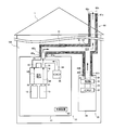
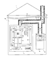
- FIG. 1 is a schematic diagram showing a schematic configuration of the power generation system according to Embodiment 1 of the present invention.
- the power generation system 100 according to the first embodiment is arranged inside a building 1.
- the power generation system 100 includes a fuel cell system 10, a combustion device 30, a control device 50, and a supply / exhaust mechanism 60.
- the fuel cell system 10 includes a housing 11.
- a fuel gas supply device 12, an oxidant gas supply device 13, a fuel cell 14, and a ventilator (air supply device) 15 are accommodated in the housing 11.
- the control device 50 is also disposed in the housing 11. In the first embodiment, the configuration in which the control device 50 is disposed in the housing 11 is illustrated, but the present invention is not limited to this.
- the control device 50 may be configured to be disposed outside the housing 11.
- a hole 16 penetrating in the thickness direction of the wall portion is provided at an appropriate position of the wall portion constituting the housing 11.
- the hole 16 is connected to a first end 60 a of a double pipe constituting the air supply / exhaust mechanism 60.
- the inner flow path of the double pipe forms the exhaust gas flow path 61
- the outer flow path forms the air supply flow path 62.
- the first end portion 60 a of the air supply / exhaust mechanism 60 forms a first exhaust gas upstream end 61 a of the exhaust gas passage 61 and a first air supply downstream end 62 a of the air supply passage 62.
- the air supply / exhaust mechanism 60 has a second end 60b connected to the combustion device 30 and a third end 60c located outside the building 1 in addition to the first end 60a.
- the exhaust gas flow path 61 inside the double pipe forms the second exhaust gas upstream end 61b at the second end 60b and the exhaust gas common downstream end 61c at the third end 60c.
- the outer air supply flow path 62 forms a second air supply downstream end 62b at the second end portion 60b, and forms an air supply common upstream end 62c at the third end portion 60c.
- the exhaust gas flow channel 61 includes a flow channel extending from the first exhaust gas upstream end 61a, a flow channel extending from the second exhaust gas upstream end 61b, and a merging portion 61d where these flow channels merge.
- the air supply channel 62 is formed so as to be in contact with the exhaust gas channel 61 and surround the outer periphery thereof.
- the first exhaust gas upstream end 61a of the exhaust gas flow channel 61 is connected to the casing 11, and guides the exhaust gas from the fuel cell system 10 from the exhaust gas common downstream end 61c to the outside. Further, the first air supply downstream end 62 a of the air supply flow path 62 is connected to the housing 11, and the outside air (air supply) taken from the air supply common upstream end 62 c is used as the housing 11 of the fuel cell system 10. Lead in.
- the fuel gas supplier 12 supplies fuel gas (hydrogen gas) to the fuel cell 14 so that the flow rate thereof can be adjusted.
- the specific configuration of the fuel gas supply device 12 is not limited.
- a hydrogen generator or a hydrogen cylinder that generates hydrogen from a hydrocarbon-based source gas may be employed, or a configuration that can supply hydrogen gas such as a hydrogen storage alloy may be employed.
- a fuel gas supply channel 20 serving as a fuel gas channel is connected between the fuel gas supplier 12 and the fuel cell 14 (more precisely, the inlet of the fuel gas channel 14A of the fuel cell 14). ing.
- the oxidant gas supply unit 13 supplies the oxidant gas (air) to the fuel cell 11 so that the flow rate thereof can be adjusted.
- the specific configuration of the oxidant gas supply device 13 is not limited. For example, you may be comprised with fans, such as a fan and a blower. Note that an oxidant gas supply flow path serving as a flow path for the oxidant gas is provided between the oxidant gas supply unit 13 and the fuel cell 14 (more precisely, the inlet of the oxidant gas flow path 14B of the fuel cell 14). 21 is connected.
- the fuel cell 14 has an anode and a cathode (both not shown).
- the fuel gas is supplied to the anode while flowing through the fuel gas passage 14A.
- the oxidant gas is supplied to the cathode while flowing through the oxidant gas flow path 14B.
- the fuel gas supplied to the anode and the oxidant gas supplied to the cathode react to generate electricity and heat.
- the generated electricity is supplied to an external power load (for example, home electrical equipment) by a power regulator (not shown).
- the generated heat is recovered by a heat medium flowing through a heat medium flow path (not shown).
- the heat recovered by the heat medium can be used, for example, to heat water.
- the fuel cell 14 can be any of various fuel cells such as a polymer electrolyte fuel cell and a solid oxide fuel cell. Furthermore, since the structure of the fuel cell 14 is the same as that of a general fuel cell, its detailed description is omitted.
- the upstream end of the off-fuel gas channel 22 is connected to the outlet of the fuel gas channel 14A.
- the downstream end of the off fuel gas passage 22 is connected to the first exhaust gas upstream end 61 a of the exhaust gas passage 61.
- the upstream end of the off-oxidant gas channel 23 is connected to the outlet of the oxidant gas channel 14B.
- the downstream end of the off-oxidant gas passage 23 is connected to the first exhaust gas upstream end 61 a of the exhaust gas passage 61.
- the off-fuel gas passage 22 and the off-oxidant gas passage 23 are connected to the exhaust gas passage 61 after joining on the way.
- off-fuel gas fuel gas that has not been used in the fuel cell 14
- the oxidant gas (hereinafter referred to as off-oxidant gas) that has not been used in the fuel cell 14 is discharged from the outlet of the oxidant gas flow path 14B to the exhaust gas flow path 61 through the off-oxidant gas flow path 23.
- the off-fuel gas discharged to the discharge channel 61 is diluted with the off-oxidant gas and discharged to the outside of the building 1.
- the ventilator 15 is connected to the first exhaust gas upstream end 61 a of the exhaust gas flow channel 61 through the ventilation flow channel 24.
- the ventilation channel 24 is also connected to the exhaust gas channel 61 after joining the off-fuel gas channel 22 and the off-oxidant gas channel 23. Therefore, when the ventilator 15 is operated, air outside the fuel cell system 10 (here, air outside the building 1) is formed from the hole 16 (more precisely, the first air supply upstream end 62a) forming the air supply port. It is supplied into the housing 11. And the gas (mainly air) in the housing
- the ventilator 15 may have any configuration as long as the inside of the housing 11 can be ventilated.
- a fan or a blower can be used as the ventilator 15.
- casing 11 was illustrated, it is not limited to this, You may comprise so that it may arrange
- the off-fuel gas, the off-oxidant gas, and the gas (mainly air) exhausted from the housing 11 by ventilation are discharged from the fuel cell system 10 to the exhaust gas flow path 61. It is illustrated as exhaust gas discharged
- the exhaust gas from the fuel cell system 10 is not limited to these gases.
- gas (combustion exhaust gas, hydrogen-containing gas, etc.) discharged from the hydrogen generator can also be included in the exhaust gas from the fuel cell system 10. .
- the oxidant gas and the gas (air) supplied into the casing 11 by ventilation are exemplified as the outside air supplied to the fuel cell system 10.
- the outside air supplied to the fuel cell system is not limited to these gases (air).
- the fuel gas supply device 12 is configured with a hydrogen generator, combustion air supplied to the hydrogen generator, or selective oxidized air when the hydrogen generator includes a selective oxidizer, It can be included in the outside air supplied to the fuel cell system 10.
- air supplied to the anode of the fuel cell 14 to prevent poisoning of the catalyst by carbon monoxide (bleed air) can also be included in the outside air.
- the combustion apparatus 30 includes a combustor 31, a combustion fan 32 that supplies air to the combustor 31 via a combustion air supply flow path 33, and a casing 34 that houses these.
- the combustion fan 32 may have any configuration as long as the combustion air can be supplied to the combustor 31, and may be configured by fans such as a fan and a blower, for example.
- Combustion fuel such as combustible gas such as natural gas or liquid fuel such as kerosene is supplied to the combustor 31 from a combustion fuel supply unit (not shown). And in the combustor 31, by burning the combustion air supplied from the combustion fan 32 and the combustion fuel supplied from the combustion fuel supply device, heat is generated and combustion exhaust gas is generated. The generated heat can be used to heat water. That is, the combustion device 30 may be used as a boiler.
- the upstream end of the combustion exhaust gas passage 35 is connected to the combustor 31, and the downstream end thereof is connected to the second exhaust gas upstream end 61 b of the exhaust gas passage 61. Therefore, the combustion exhaust gas generated by the combustor 31 is discharged to the exhaust gas passage 61 via the combustion exhaust passage 35.
- the combustion exhaust gas discharged to the exhaust gas passage 61 flows through the exhaust gas passage 61 and is discharged to the outside of the building 1.
- a hole 36 penetrating in the thickness direction of the wall portion is provided at an appropriate position of the wall portion constituting the casing 34 of the combustion device 30, and the second end portion 60 b of the air supply / exhaust mechanism 60 is provided in the hole 36. Is connected.
- the second exhaust gas downstream end 61b of the inner exhaust gas passage 61 is connected to the combustor 31 via the combustion exhaust gas passage 35 as described above.
- the second supply upstream end 62 b of the outer supply passage 62 communicates with the inside of the housing 34 through the hole 36. Accordingly, when the combustion device 30 operates, the relatively high-temperature combustion exhaust gas discharged from the combustion device 30 flows through the exhaust gas passage 61 and is discharged to the outside. Further, the air flowing through the supply air flow path 62 is heated by exchanging heat with the high-temperature combustion exhaust gas flowing through the exhaust gas flow path 61.
- the control device 50 may take any form as long as it has a function of controlling each device constituting the power generation system 100.
- the control device 50 includes an arithmetic processing unit exemplified by a microprocessor, a CPU, and the like, and a storage unit configured by a memory that stores a program for executing each control operation. I have.
- the arithmetic processing unit reads out a predetermined program stored in the storage unit and executes it, thereby executing various functions described below in addition to the basic power generation operation of the power generation system 100. To realize.
- control device 50 is not only configured as a single control device, but also configured as a controller group in which a plurality of control devices cooperate to execute control of the power generation system 100. I do not care.
- control apparatus 50 may be comprised by the microcomputer, and may be comprised by MPU, PLC (programmable logic controller), a logic circuit, etc.
- the power generation system 100 includes an air temperature detector 51 that detects the temperature of the air supplied to the casing 11 of the fuel cell system 10.
- the air temperature detector 51 is disposed in the air supply passage 62 on the way from the common air supply upstream end 62c to the first air supply downstream end 62a. More precisely, the fuel cell system 10 and the combustion device 30 are disposed between the branching portion toward each of the fuel cell system 10 and the combustion device 30 and the first supply air downstream end 62a.
- the arrangement of the air temperature detector 51 is not limited to this.
- the air temperature detector 51 may be arranged such that only the sensor portion is exposed in the air supply channel 62 and the other part is arranged outside the air supply channel 62.
- the power generation system 100 executes a freezing prevention process in the system when the temperature of the supply air is low (when it is equal to or lower than a predetermined first temperature).
- activation refers to an operation during the transition of the fuel cell 14 from the stopped state to the power generation state.
- the start of operation of the ventilator 15 for supplying the oxidant gas to the fuel cell 14 can be set as the starting point of “startup”.
- the ventilator 15 may be operated also in the freeze prevention process. In this case, the ventilator 15 is operated only for the purpose of the freeze prevention process, the freeze prevention process and the fuel cell. It should be noted that there are cases where the system 10 is intended for both startup purposes.
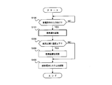
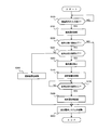
- FIG. 2 is a flowchart illustrating the operation of the power generation system 100 according to the first embodiment.
- the control device 50 determines whether or not a power generation command is input to the fuel cell system 10 (step S100).
- a user of the fuel cell system 10 operates a remote controller (not shown) to operate the fuel cell system 10 or a fuel cell that is scheduled in advance. For example, when the operation start time of the system 10 is reached.
- step S100: No When it is determined that the power generation command is not input (step S100: No), the control device 50 repeats the process of step S100 until the power generation command is input. On the other hand, when it determines with the electric power generation instruction
- an upper limit temperature at which freezing in the system by the intake air taken into the casing 11 of the fuel cell system 10 is acquired in advance by a test or the like can be set as the first temperature T1.
- an appropriate predetermined value for example, zero degree may be set as the first temperature T1 without performing a test or the like.
- step S200 If it is determined that the supply air is equal to or lower than the first temperature T1 (step S200: YES), the combustion device 30 is activated (step S300). Then, the fuel cell system 10 is activated (step S400). On the other hand, when it is determined that the supply air is higher than the first temperature (step S200: NO), the fuel cell system 10 is started without starting the combustion device 30 (step S400).
- the supply air is heated by the high-temperature combustion exhaust gas generated by starting the combustion device 30 even when the outside air taken in as supply air is at a low temperature. It is possible to prevent freezing in the system due to energy.
- step S400 the flow which performs starting (step S400) of the fuel cell system 10 after starting of the combustion apparatus 30 (step S300) was shown, it is not restricted to this.
- the start-up of the combustion apparatus 30 and the start-up of the combustion cell system 10 may be performed at substantially the same timing, or even if the start-up of the fuel cell system 10 is earlier than the start-up of the combustion apparatus 30 if the time is short. Good.
- the combustion device 30 when starting the combustion device 30 in step S300, the combustion device 30 may already be operating. For example, when a boiler is employed as the combustion device 30, the combustion device 30 operates in accordance with the hot water supply status regardless of the presence or absence of a power generation command. Therefore, in the case of such a configuration, before starting the combustion device 30 in step S300, it is determined whether or not the combustion device 30 is in operation, and processing for starting up the combustion device 30 when it is not in operation. (Step S300) may be executed.
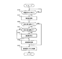
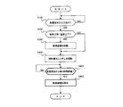
- FIG. 3 is a flowchart illustrating the operation of the power generation system 100 according to the second embodiment. Also in the flow shown in FIG. 3, the processing of each step shown in the first embodiment is executed. However, in the present Example 2, the process (step S101) which starts the ventilator 15 is performed between the process of step S100 and the process of step S200. That is, when a power generation command is input (step S100), the temperature of the supply air is determined (step S200) after the ventilator 15 is activated (step S101).
- step S200 determines the temperature of the supply air (step S200) based on the taken-in temperature of the outside air. Therefore, freezing in the system due to air supply can be prevented more reliably. In addition, since a more appropriate temperature determination can be made to prevent freezing, unnecessary start-up of the combustion device 30 can be prevented, and waste of fuel can be suppressed.
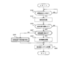
- FIG. 4 is a flowchart illustrating the operation of the power generation system 100 according to the third embodiment.
- the processing of each step shown in the second embodiment is executed.
- each process of steps S201 and S202 is executed between the process of step S200 and the process of step S300.
- step S100 when there is an input of a power generation command (step S100), the ventilator 15 is activated (step S101), and it is determined that the supply air is equal to or lower than the first temperature T1 (step S200: YES), this In Example 3, it is further determined whether the supply air is equal to or lower than the second temperature T2 (step S201).
- the second temperature T2 is set in advance as a temperature lower than the first temperature T1.
- step S201: YES when it determines with air supply being 2nd temperature T2 or less (step S201: YES), the ventilator 15 started by step S101 is stopped (step S202), and the combustion apparatus 30 is started (step S300). .
- step S201: NO when it determines with air supply being larger than 2nd temperature T2 (step S201: NO), the combustion apparatus 30 is started, without stopping the ventilator 15 (step S300). Thus, after starting the combustion apparatus 30, the fuel cell system 10 is started (step S400).
- the ventilator 15 is stopped when the supply air is at a low temperature equal to or lower than the second temperature T2, freezing in the system due to the low-temperature supply air can be prevented.
- the combustion apparatus 30 is operated while the ventilator 15 is stopped, the exhaust gas flow path 61 can be heated by the high-temperature combustion exhaust gas. Therefore, the supply air flowing in contact with the exhaust gas passage 61 can be heated.
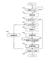
- FIG. 5 is a flowchart illustrating an operation according to the fourth embodiment of the power generation system 100.
- the processes of steps S100, S101, S200, and S201 illustrated in the third embodiment are executed.
- step S201 when it determines with air supply being 2nd temperature or less, the process different from Example 3 is performed.
- step S201: YES when the control device 50 determines that the supply air is equal to or lower than the second temperature (step S201: YES), the control device 50 stops the ventilator 15 (step S202) and starts the combustion device 30 (step S203). ). Next, the elapsed time after starting the combustion apparatus is measured, and it is determined whether or not the first time has elapsed since the start of combustion (step S204). If the first time has not elapsed (step S204: NO), the process of step S204 is repeated. On the other hand, if it is determined that the first time has passed (step S204: YES), the ventilator 15 that has been stopped is started again (step S206), and then the fuel cell system 10 is started (step S400). When it is determined that the supply air is higher than the second temperature (step S201: NO), the combustion apparatus 30 is started (step S300) and then the fuel cell system 10 is started (step S201: NO) (step S201). S400).
- the introduction of the supply air can be stopped until the combustion apparatus 30 is activated until the high-temperature combustion exhaust gas can be generated.
- the intake air is taken in after the combustion device 30 has been started, so that high-temperature combustion exhaust gas can be generated, so that even low-temperature supply air can be reliably heated.
- FIG. 6 is a flowchart illustrating an operation according to the fifth embodiment of the power generation system 100.
- the flow shown in FIG. 6 is different from the flow shown in the fourth embodiment in that the process of step S204 is replaced with the process of step S205. That is, in the fourth embodiment, the restart timing of the ventilator 15 that has been stopped is determined based on the elapsed time since the start of the combustion device 30. On the other hand, in the fifth embodiment, the same timing is determined based on the temperature of the supply air detected by the supply air temperature detector 51.
- step S205 determines whether or not the supply air is equal to or higher than a predetermined third temperature. If the temperature is lower than the third temperature T3 (step S205: NO), the process of step S205 is repeated. On the other hand, if it is determined that the temperature is equal to or higher than the third temperature T3 (step S205: YES), the ventilator 15 that has been stopped is started again (step S206), and then the fuel cell system 10 is started (step S400).
- the “third temperature” is not particularly limited as long as it is higher than the second temperature T2, and can be appropriately determined in consideration of the installation environment of the power generation system 100 and the like.
- FIG. 7 is a flowchart illustrating the operation of the power generation system 100 according to the sixth embodiment. Also in the flow shown in FIG. 7, the processing of each step shown in the flow of Embodiment 1 (see FIG. 2) is executed. However, in the sixth embodiment, after starting the fuel cell system (step S400), processing (steps S401 and S402) for stopping the combustion apparatus 30 based on a predetermined condition is executed.
- the control device 50 starts the fuel cell system 10 after the supply air is equal to or lower than the first temperature T1 (step S200: YES) and the combustion device 30 is started (step S300) (step S300). S400). And the elapsed time after starting the combustion apparatus 30 is measured, and it is determined whether 2nd time passed since the combustion start (step S401). If the second time has not elapsed (step S401: NO), the process of step S401 is repeated. During this time, the fuel cell system 10 performs the start-up operation or the power generation operation. On the other hand, when determining that the second time has elapsed (step S401: YES), the control device 50 stops the combustion device 30 (step S403). That is, the operation of the fuel cell system 10 is continued with the combustion device 30 stopped.
- the exhaust gas temperature becomes sufficiently high after a predetermined time has elapsed from the start-up, so that the high temperature exhaust gas flowing through the exhaust gas flow channel 61 and the supply air flowing through the air supply flow channel 62 are between
- the air supply can be appropriately heated by this heat exchange.
- the fuel cell system 10 rises in temperature as a whole due to heat generated by the hydrogen generator when a predetermined time elapses from starting, so that freezing due to low-temperature air supply hardly occurs. Therefore, if the operation flow as in the sixth embodiment is adopted, the combustion device 30 is stopped when the possibility of freezing is reduced (when the second time has elapsed), and therefore, the fuel flow in the combustion device 30 is reduced. Waste can be prevented.
- FIG. 8 is a flowchart illustrating an operation according to the seventh embodiment of the power generation system 100.
- the flow shown in FIG. 8 is different from the flow shown in Embodiment 6 in that the process of step S402 is replaced with the process of step S403. That is, in the sixth embodiment, the stop timing of the combustion device 30 is determined based on the elapsed time from the start of the combustion device 30. On the other hand, in the seventh embodiment, the same timing is determined based on the temperature of the supply air detected by the supply air temperature detector 51.
- the control device 50 activates the combustion device 30 (step S300), and activates the fuel cell system 10 (step S400), and acquires the temperature of the air supply from the air temperature detector 51. Then, it is determined whether or not the supply air is equal to or higher than a predetermined fourth temperature T4 (step S402). If it is lower than the fourth temperature T4 (step S402: NO), this step S402 is repeated. During this time, the fuel cell system 10 performs the start-up operation or the power generation operation. On the other hand, when determining that the temperature is equal to or higher than the fourth temperature T4 (step S402: YES), the control device 50 stops the combustion device 30 (step S403). That is, the operation of the fuel cell system 10 is continued with the combustion device 30 stopped.
- the fourth temperature T4 may be acquired in advance by a test or the like as the temperature of the supply air when the system does not freeze even when the combustion device 30 is stopped.
- an appropriate predetermined value for example, a temperature of zero degrees or more may be set as the fourth temperature T4 without performing a test or the like.
- the combustion device 30 is stopped (step S403) when a predetermined condition is satisfied (step S401: YES, step S402: YES), but then the combustion device 30 as necessary. May be activated again. For example, even after the combustion apparatus 30 is stopped, the temperature of the supply air is continuously detected by the supply air temperature detector 51, and the combustion apparatus 30 is started when the temperature becomes lower than the first temperature T1. Also good.
- FIG. 9 is a flowchart illustrating an operation according to the eighth embodiment of the power generation system 100.
- the process of each step of the flow shown in the second embodiment is executed, except that steps S207 and S208 are further executed.
- the ventilator 15 is activated (step S101), and when the supply air is equal to or lower than the first temperature T1 (step S200: YES), the combustion device 30 is stopped. It is determined whether it is in the middle (step S207). Here, if the engine is stopped, the combustion apparatus 30 is activated (step S300) and the fuel cell system 10 is activated (step S400) as in the second embodiment. On the other hand, when it is determined that the combustion apparatus 30 is not stopped, that is, is operating (step S207: NO), the amount of combustion in the combustion apparatus 30 is increased (step S208). For example, the amount of combustion fuel supplied to the combustor 31 is increased, and the amount of combustion air supplied by the combustion fan 32 is increased.
- the combustion apparatus 30 when the combustion apparatus 30 is already operating and the supply air is at the first temperature T1 or less, the amount of combustion in the combustion apparatus 30 can be increased, and the amount of heat of the combustion exhaust gas can be increased. it can. Therefore, the supply air can be heated more appropriately.
- FIG. 10 is a schematic diagram illustrating a schematic configuration of the power generation system according to the second embodiment.
- the power generation system 100 according to the second embodiment has the same configuration as that of the power generation system 100 according to the first embodiment, but differs in the following points. That is, the combustion device 30 includes a heat exchanger 37 and a water circulation channel 38.
- the heat exchanger 37 is provided in the middle of the combustion exhaust gas flow path 35, and the water circulation flow path 38 is provided between the heat exchanger 37 and the double pipe forming the air supply / exhaust mechanism 60.
- the water circulation channel 38 guides the water heated by the combustion exhaust gas flowing through the heat exchanger 37 to the double pipe forming the air supply / exhaust mechanism 60 and heats it between the supply air flowing through the air supply channel 62. Let them exchange. Water whose temperature has decreased due to heat exchange with the supply air is returned to the heat exchanger 37 via the water circulation passage 38 and is heated again by the combustion exhaust gas. As described above, a part of the air supply flow path 62 forms the heating unit 39 that is heated by the heat of the combustion exhaust gas.
- the heating unit 39 is provided in a portion of the air supply passage 62 from the branching portion with the combustion device 30 to the fuel cell system 10. In more detail, in the said part, it is provided in the position of the upstream of the flow direction of air supply rather than the installation position of the air temperature detector 51. FIG. However, the arrangement of the heating unit 39 is not limited to this, and can be provided at an appropriately selected position.
- the water circulation channel 38 may be passed through the air supply channel 62.
- fins may be provided in the water circulation channel 38 in the air supply channel 62 to improve the heat exchange efficiency.
- FIG. 11 is a schematic diagram illustrating a schematic configuration of the power generation system according to the third embodiment.
- the power generation system 100 according to the second embodiment has the same configuration as that of the power generation system 100 according to the first embodiment.
- the configuration of the fuel gas supplier 12 and the off-fuel from the fuel cell 14 are the same. It differs in the flow path where gas is discharged.
- the fuel gas supply device hereinafter referred to as “hydrogen generation device” in this embodiment
- hydrogen generation device 12 includes a reformer 12a, a combustor 12b, and a combustion fan 12c.
- the combustor 12 b is connected to the downstream end of the off-fuel gas passage 22 from the fuel cell 14, and off-fuel gas from the fuel cell 14 passes through the off-fuel gas passage 22 as combustion fuel. Supplied.
- a combustion fan 12c is connected to the combustor 12b via an air supply flow path 25.
- the combustion fan 12c may have any configuration as long as it can supply combustion air to the combustor 12b.
- the combustion fan 12c may be configured by fans such as a fan and a blower.
- the upstream end of the combustion exhaust gas passage 26 is connected to the combustor 12b, and the downstream end of the combustion exhaust gas passage 26 is connected to the exhaust gas passage 61 (more precisely, the first exhaust gas upstream end 61a). Connected.
- a combustor 12b In such a combustor 12b, the supplied off-fuel gas and combustion air are combusted, and combustion exhaust gas is generated to generate heat.
- the combustion exhaust gas generated by the combustor 12 b is heated to the reformer 12 a and the like, and then discharged to the outside of the power generation system 100, that is, outside the building 1 through the combustion exhaust gas passage 26 and the exhaust gas passage 61. .
- the reformer 12a is connected to a raw material supply device and a steam supply device (not shown), and the raw material and water vapor are supplied.
- a raw material natural gas mainly composed of methane, LP gas, or the like can be used.
- the reformer 12a has a reforming catalyst.
- this reforming catalyst for example, any substance may be used as long as it can catalyze a steam reforming reaction that generates a hydrogen-containing gas from a raw material and steam.
- a ruthenium catalyst in which ruthenium (Ru) is supported on a catalyst carrier such as alumina, a nickel catalyst in which nickel (Ni) is supported on a similar catalyst carrier, or the like can be used.
- a hydrogen-containing gas is generated by a reforming reaction between the supplied raw material and steam.
- the generated hydrogen-containing gas is supplied as a fuel gas to the fuel gas passage 14A of the fuel cell 14 via the fuel gas supply passage 20.
- the hydrogen-containing gas generated by the reformer 12a is supplied to the fuel cell 14 as a fuel gas.
- the present invention is not limited to this.
- carbon monoxide is reduced by passing hydrogen generated by the reformer 12 a through a shift catalyst included in the shift converter, and further a carbon monoxide remover having an oxidation catalyst or a methanation catalyst. It is good also as supplying to the fuel cell 14 after letting pass.
- a copper-zinc catalyst can be used as an example of the shift catalyst
- a ruthenium catalyst can be used as an example of the oxidation catalyst or the methanation catalyst.
- the off fuel gas from the fuel cell 14 is supplied as a combustion fuel to the combustor 12b.
- the combustion fuel may be separately supplied from the combustion fuel supplier to the combustor 12b.
- the hydrogen generator 12 in order to start the fuel cell system 10, the hydrogen generator 12 is operated and the reforming catalyst in the reformer 12a is subjected to the reforming reaction. It is necessary to raise it to a temperature suitable for Therefore, combustion fuel and combustion air are combusted in the combustor 12b.
- the combustion fan 12 c when the combustion fan 12 c is operated in order to supply combustion air to the combustor 12 b, outside air is supplied into the housing 11 through the air supply passage 62.
- the combustion device 30 step S300
- the outside air flowing through the supply air flow channel 62 is heated by the combustion exhaust gas from the combustion device 30 flowing through the exhaust gas flow channel 61. Therefore, it is possible to prevent water in the fuel cell system 10 from freezing even when the outside air temperature is below freezing point.
- the power generation system and the operation method thereof according to the present invention are capable of preventing the water in the system from being frozen by supply air even when the outside air temperature is low, particularly at the time of starting the fuel cell system. Can be applied.
Landscapes
- Engineering & Computer Science (AREA)
- Chemical & Material Sciences (AREA)
- Life Sciences & Earth Sciences (AREA)
- Manufacturing & Machinery (AREA)
- Sustainable Development (AREA)
- Sustainable Energy (AREA)
- Chemical Kinetics & Catalysis (AREA)
- Electrochemistry (AREA)
- General Chemical & Material Sciences (AREA)
- Combustion & Propulsion (AREA)
- Fuel Cell (AREA)
Abstract
Description
図1は、本発明の実施の形態1に係る発電システムの概略構成を示す模式図である。図1に示すように、本実施の形態1に係る発電システム100は、建物1の内部に配置されている。発電システム100は、燃料電池システム10、燃焼装置30、制御装置50、及び、給排気機構60を備えている。
図2は、発電システム100の実施例1に係る動作を示すフローチャートである。この図2に示すように、制御装置50は、燃料電池システム10に対して発電指令が入力されたか否か判定する(ステップS100)。この発電指令が入力される例としては、燃料電池システム10の使用者が、図示されていないリモコンを操作して、燃料電池システム10が作動するように操作した場合や、予めスケジュールされた燃料電池システム10の作動開始時間になった場合などが挙げられる。
図3は、発電システム100の実施例2に係る動作を示すフローチャートである。図3に示すフローでも、実施例1に示した各ステップの処理を実行する。但し、本実施例2では、ステップS100の処理とステップS200の処理との間に、換気器15を起動する処理(ステップS101)を実行する。即ち、発電指令の入力があった場合(ステップS100)には、換気器15を起動(ステップS101)した後に、給気の温度判定(ステップS200)を行う。
図4は、発電システム100の実施例3に係る動作を示すフローチャートである。図4に示すフローでは、実施例2に示した各ステップの処理を実行する。但し、本実施例3では、ステップS200の処理とステップS300の処理との間に、ステップS201,S202の各処理を実行する。
図5は、発電システム100の実施例4に係る動作を示すフローチャートである。図5に示すフローでは、実施例3に示したステップS100,S101,S200,S201の各処理を実行する。そして、ステップS201において、給気が第2温度以下であると判定した場合に、実施例3とは異なる処理を実行する。
図6は、発電システム100の実施例5に係る動作を示すフローチャートである。図6に示すフローでは、実施例4に示したフローのうち、ステップS204の処理がステップS205の処理に置換されている点が相違する。即ち、実施例4では、停止させた換気器15の再起動のタイミングを、燃焼装置30の起動時からの経過時間に基づいて判断するものである。これに対して本実施例5では、同タイミングを、給気温検知器51により検知された給気の温度に基づいて判断する。
図7は、発電システム100の実施例6に係る動作を示すフローチャートである。図7に示すフローでも、実施例1のフロー(図2参照)に示した各ステップの処理を実行する。但し、本実施例6では、燃料電池システムの起動(ステップS400)の後に、所定条件に基づいて燃焼装置30を停止させる処理(ステップS401,S402)を実行する。
図8は、発電システム100の実施例7に係る動作を示すフローチャートである。図8に示すフローでは、実施例6に示したフローのうち、ステップS402の処理がステップS403の処理に置換されている点が相違する。即ち、実施例6では、燃焼装置30の停止タイミングを、燃焼装置30の起動時からの経過時間に基づいて判断するものである。これに対して本実施例7では、同タイミングを、給気温検知器51により検知された給気の温度に基づいて判断する。
図9は、発電システム100の実施例8に係る動作を示すフローチャートである。図9に示すフローでは、実施例2に示したフロー(図3参照)の各ステップの処理を実行するが、ステップS207,S208を更に実行する点が相違する。
図10は、実施の形態2に係る発電システムの概略構成を示す模式図である。本実施の形態2に係る発電システム100は、実施の形態1に係る発電システム100と大部分において同じ構成を備えているが、以下の点で異なる。即ち、燃焼装置30は、熱交換器37と水循環流路38とを備えている。
図11は、実施の形態3に係る発電システムの概略構成を示す模式図である。本実施の形態2に係る発電システム100は、実施の形態1に係る発電システム100と大部分において同じ構成を備えているが、燃料ガス供給器12の構成、及び、燃料電池14からのオフ燃料ガスの排出される流路において異なっている。具体的に説明すると、燃料ガス供給器(以下、本実施の形態では「水素生成装置」と称する)12は、改質器12a、燃焼器12b、及び燃焼ファン12cを有している。
10 燃料電池システム
11 筐体
14 燃料電池
30 燃焼装置
50 制御装置
51 給気温検知器
60 給排気機構
61 排ガス流路
62 給気流路
100 発電システム
Claims (11)
- 給気流路と、
燃料ガスと酸化剤ガスとを用いて発電する燃料電池、該燃料電池を収納する筐体、前記給気流路を介して外気を前記筐体へ供給する空気供給器、及び、前記筐体への給気の温度を検知する給気温検知器、を有する燃料電池システムと、
燃料を燃焼して熱量を生成する燃焼器を有する燃焼装置と、
該燃焼装置で生じた燃焼排ガスを外部へ排出する排ガス流路と、
制御装置と、
を備える発電システムであって、
前記給気流路と前記排ガス流路とは、互いの流路を流れる媒体間で熱交換が可能なように構成されており、
前記制御装置は、前記燃料電池システムを起動させる場合であって、前記給気温検知器が検知した温度が所定の第1温度以下の場合は、前記燃焼装置を動作させる、発電システム。 - 前記給気温検知器は、前記給気流路又は前記筐体内に配置されており、
前記制御装置は、前記燃料電池システムを起動させる場合であって、前記空気供給器を動作させた後に前記給気温検知器が検知した温度が前記第1温度以下の場合には、前記燃焼装置を動作させる、請求項1に記載の発電システム。 - 前記制御装置は、前記燃料電池システムを起動させる場合であって、前記空気供給器を動作させた後に前記給気温検知器が検知した温度が所定の第2温度以下の場合には、前記空気供給器を停止させ、前記燃焼装置を動作させる、請求項2に記載の発電システム。
- 前記制御装置は、前記給気温検知器が前記第2温度以下を検知することにより前記空気供給器を停止させた場合は、所定の第1時間だけ前記燃焼装置を動作させた後に、前記空気供給器を動作させ、前記燃料電池システムを起動させる、請求項3に記載の発電システム。
- 前記制御装置は、前記給気温検知器が前記第2温度以下を検知することにより前記空気供給器を停止させた場合は、前記給気温検知器が所定の第3温度以上を検知するまで前記燃焼装置を動作させた後に、前記空気供給器を動作させ、前記燃料電池システムを起動させる、請求項3に記載の発電システム。
- 前記第2温度は、前記第1温度以下であるように設定されている、請求項3乃至5の何れかに記載の発電システム。
- 前記制御装置は、前記燃料電池システムを起動させる場合であって、前記給気温検知器が検知した温度が前記第1温度以下の場合は、所定の第2時間だけ前記燃焼装置を動作させた後に、該燃焼装置を停止させる、請求項1乃至6の何れかに記載の発電システム。
- 前記制御装置は、前記燃料電池システムを起動させる場合であって、前記給気温検知器が検知した温度が前記第1温度以下の場合は、前記給気温検知器が検知した温度が所定の第4温度以上を検知するまで前記燃焼装置を動作させた後に、該燃焼装置を停止させる、請求項1乃至6の何れかに記載の発電システム。
- 前記制御装置は、前記給気温検知器が検知した温度が前記第1温度以下の場合であって、前記燃料電池システムを起動させる場合には、該燃料電池システムの起動より先に前記燃焼装置を動作させる、請求項1乃至8の何れかに記載の発電システム。
- 前記排ガス流路は、前記燃料電池システムに接続された上流端から延設された流路と、前記燃焼装置に接続された上流端から延設された流路と、両流路が合流する合流部と、該合流部から大気開放された下流端へ延設された流路と、を有し、
前記給気流路は、前記排ガス流路の少なくとも一部に接するようにして配設されている、請求項1乃至9の何れかに記載の発電システム。 - 燃料電池システムと、燃焼装置と、外気を前記燃料電池システムへ供給する給気流路と、で生じた燃焼排ガスを外部へ排出する排ガス流路と、を備え、前記給気流路及び前記排ガス流路が、互いの流路を流れる媒体間で熱交換可能に構成されている、発電システムの運転方法であって、
前記給気流路を介して前記燃料電池システムへ供給される給気の温度を検知するステップと、
給気の温度が所定の第1温度以下か否かを判定するステップと、
前記燃料電池システムを起動させる場合に、給気の温度が前記第1温度以下であった場合に、前記燃焼装置を動作させるステップと、
を備える、発電システムの運転方法。
Priority Applications (4)
| Application Number | Priority Date | Filing Date | Title |
|---|---|---|---|
| RU2013148019/07A RU2013148019A (ru) | 2011-03-29 | 2012-03-29 | Система производства энергии и способ ее эксплуатации |
| US14/002,302 US9385384B2 (en) | 2011-03-29 | 2012-03-29 | Power generation system and method of operating the same |
| EP12765572.8A EP2677585B1 (en) | 2011-03-29 | 2012-03-29 | Power generation system and method of operating the same |
| JP2013507193A JP6048680B2 (ja) | 2011-03-29 | 2012-03-29 | 発電システム及びその運転方法 |
Applications Claiming Priority (2)
| Application Number | Priority Date | Filing Date | Title |
|---|---|---|---|
| JP2011071645 | 2011-03-29 | ||
| JP2011-071645 | 2011-03-29 |
Publications (1)
| Publication Number | Publication Date |
|---|---|
| WO2012132445A1 true WO2012132445A1 (ja) | 2012-10-04 |
Family
ID=46930217
Family Applications (1)
| Application Number | Title | Priority Date | Filing Date |
|---|---|---|---|
| PCT/JP2012/002171 Ceased WO2012132445A1 (ja) | 2011-03-29 | 2012-03-29 | 発電システム及びその運転方法 |
Country Status (5)
| Country | Link |
|---|---|
| US (1) | US9385384B2 (ja) |
| EP (1) | EP2677585B1 (ja) |
| JP (1) | JP6048680B2 (ja) |
| RU (1) | RU2013148019A (ja) |
| WO (1) | WO2012132445A1 (ja) |
Cited By (3)
| Publication number | Priority date | Publication date | Assignee | Title |
|---|---|---|---|---|
| WO2014034141A1 (ja) * | 2012-08-30 | 2014-03-06 | パナソニック株式会社 | 発電システムおよびその運転方法 |
| WO2014136454A1 (ja) * | 2013-03-08 | 2014-09-12 | パナソニック株式会社 | 発電システム及び発電システムの運転方法 |
| JP2014216171A (ja) * | 2013-04-25 | 2014-11-17 | パナソニック株式会社 | 燃料電池システム |
Families Citing this family (4)
| Publication number | Priority date | Publication date | Assignee | Title |
|---|---|---|---|---|
| WO2012132197A1 (ja) * | 2011-03-30 | 2012-10-04 | パナソニック株式会社 | 発電システム及びその運転方法 |
| KR101439428B1 (ko) * | 2012-12-28 | 2014-09-11 | 주식회사 경동나비엔 | 연료전지를 이용한 보일러 시스템 |
| EP3107140A4 (en) * | 2014-02-14 | 2017-03-01 | Panasonic Intellectual Property Management Co., Ltd. | Power generation system and power generation system operation method |
| JP7159721B2 (ja) * | 2018-09-11 | 2022-10-25 | トヨタ自動車株式会社 | 建物 |
Citations (8)
| Publication number | Priority date | Publication date | Assignee | Title |
|---|---|---|---|---|
| JP2004192889A (ja) * | 2002-12-10 | 2004-07-08 | Nissan Motor Co Ltd | 燃料電池システム |
| JP2006032153A (ja) * | 2004-07-16 | 2006-02-02 | Ebara Ballard Corp | 燃料電池コージェネレーションシステム |
| JP2006073446A (ja) | 2004-09-06 | 2006-03-16 | Fuji Electric Holdings Co Ltd | 燃料電池発電装置 |
| JP2006253020A (ja) * | 2005-03-11 | 2006-09-21 | Toshiba Fuel Cell Power Systems Corp | 燃料電池発電装置及び吸排気装置 |
| JP2007248009A (ja) | 2006-03-17 | 2007-09-27 | Nippon Oil Corp | コージェネレーションシステム及びその運転方法 |
| JP2008210631A (ja) | 2007-02-26 | 2008-09-11 | Kyocera Corp | 発電装置 |
| JP2009238390A (ja) | 2008-03-25 | 2009-10-15 | Equos Research Co Ltd | 燃料電池システム |
| JP2010086916A (ja) * | 2008-10-02 | 2010-04-15 | Toshiba Corp | 燃料電池システム |
Family Cites Families (13)
| Publication number | Priority date | Publication date | Assignee | Title |
|---|---|---|---|---|
| JP2002093445A (ja) | 2000-09-11 | 2002-03-29 | Equos Research Co Ltd | 燃料電池装置及びその運転方法 |
| JP2004164868A (ja) | 2002-11-08 | 2004-06-10 | Sanyo Electric Co Ltd | コージェネレーションシステムにおける貯湯方法及びその装置 |
| JP2005032585A (ja) | 2003-07-07 | 2005-02-03 | Matsushita Electric Ind Co Ltd | 燃料電池を用いた電源システム |
| WO2005112175A1 (ja) * | 2004-05-19 | 2005-11-24 | Matsushita Electric Industrial Co., Ltd. | 燃料電池システム |
| JP2006004699A (ja) | 2004-06-16 | 2006-01-05 | Ebara Corp | 非常用燃料電池発電システム |
| AT503130B1 (de) | 2006-03-15 | 2007-08-15 | Vaillant Austria Gmbh | Kombination eines heizgerätes mit einer brennstoffzellenanlage sowie ein verfahren zum betreiben dieser kombination |
| JP2008108449A (ja) | 2006-10-23 | 2008-05-08 | Aisin Seiki Co Ltd | 燃料電池システムの凍結防止装置 |
| US8206857B2 (en) * | 2007-06-26 | 2012-06-26 | Hyteon Inc. | Fuel cell combined heat and power generation |
| US8148024B2 (en) * | 2009-03-31 | 2012-04-03 | Konstantin Korytnikov | Method and apparatus for PEM fuel cell freezing protection |
| JP5513003B2 (ja) | 2009-04-21 | 2014-06-04 | 東芝燃料電池システム株式会社 | 燃料電池発電装置 |
| US20130115538A1 (en) * | 2010-12-13 | 2013-05-09 | Panasonic Corporation | Power generation system and method of operating the same |
| JP5649760B2 (ja) | 2012-04-10 | 2015-01-07 | パナソニック株式会社 | 燃料電池システム及びその運転方法 |
| WO2014034141A1 (ja) * | 2012-08-30 | 2014-03-06 | パナソニック株式会社 | 発電システムおよびその運転方法 |
-
2012
- 2012-03-29 JP JP2013507193A patent/JP6048680B2/ja not_active Expired - Fee Related
- 2012-03-29 EP EP12765572.8A patent/EP2677585B1/en not_active Not-in-force
- 2012-03-29 RU RU2013148019/07A patent/RU2013148019A/ru not_active Application Discontinuation
- 2012-03-29 US US14/002,302 patent/US9385384B2/en not_active Expired - Fee Related
- 2012-03-29 WO PCT/JP2012/002171 patent/WO2012132445A1/ja not_active Ceased
Patent Citations (8)
| Publication number | Priority date | Publication date | Assignee | Title |
|---|---|---|---|---|
| JP2004192889A (ja) * | 2002-12-10 | 2004-07-08 | Nissan Motor Co Ltd | 燃料電池システム |
| JP2006032153A (ja) * | 2004-07-16 | 2006-02-02 | Ebara Ballard Corp | 燃料電池コージェネレーションシステム |
| JP2006073446A (ja) | 2004-09-06 | 2006-03-16 | Fuji Electric Holdings Co Ltd | 燃料電池発電装置 |
| JP2006253020A (ja) * | 2005-03-11 | 2006-09-21 | Toshiba Fuel Cell Power Systems Corp | 燃料電池発電装置及び吸排気装置 |
| JP2007248009A (ja) | 2006-03-17 | 2007-09-27 | Nippon Oil Corp | コージェネレーションシステム及びその運転方法 |
| JP2008210631A (ja) | 2007-02-26 | 2008-09-11 | Kyocera Corp | 発電装置 |
| JP2009238390A (ja) | 2008-03-25 | 2009-10-15 | Equos Research Co Ltd | 燃料電池システム |
| JP2010086916A (ja) * | 2008-10-02 | 2010-04-15 | Toshiba Corp | 燃料電池システム |
Non-Patent Citations (1)
| Title |
|---|
| See also references of EP2677585A4 |
Cited By (6)
| Publication number | Priority date | Publication date | Assignee | Title |
|---|---|---|---|---|
| WO2014034141A1 (ja) * | 2012-08-30 | 2014-03-06 | パナソニック株式会社 | 発電システムおよびその運転方法 |
| JPWO2014034141A1 (ja) * | 2012-08-30 | 2016-08-08 | パナソニックIpマネジメント株式会社 | 発電システムおよびその運転方法 |
| WO2014136454A1 (ja) * | 2013-03-08 | 2014-09-12 | パナソニック株式会社 | 発電システム及び発電システムの運転方法 |
| EP2966716A4 (en) * | 2013-03-08 | 2016-03-16 | Panasonic Ip Man Co Ltd | POWER GENERATION SYSTEM AND POWER GENERATION SYSTEM OPERATION |
| JP5895245B2 (ja) * | 2013-03-08 | 2016-03-30 | パナソニックIpマネジメント株式会社 | 発電システム及び発電システムの運転方法 |
| JP2014216171A (ja) * | 2013-04-25 | 2014-11-17 | パナソニック株式会社 | 燃料電池システム |
Also Published As
| Publication number | Publication date |
|---|---|
| US9385384B2 (en) | 2016-07-05 |
| EP2677585B1 (en) | 2018-08-01 |
| JP6048680B2 (ja) | 2016-12-21 |
| US20130337354A1 (en) | 2013-12-19 |
| JPWO2012132445A1 (ja) | 2014-07-24 |
| EP2677585A1 (en) | 2013-12-25 |
| EP2677585A4 (en) | 2014-04-23 |
| RU2013148019A (ru) | 2015-05-10 |
Similar Documents
| Publication | Publication Date | Title |
|---|---|---|
| JP5190561B2 (ja) | 発電システム及びその運転方法 | |
| JP6048680B2 (ja) | 発電システム及びその運転方法 | |
| JP5336022B2 (ja) | 発電システム及びその運転方法 | |
| JP5874022B2 (ja) | 発電システムおよびその運転方法 | |
| JP5280588B2 (ja) | 発電システム及びその運転方法 | |
| JP5089829B2 (ja) | 発電システム及びその運転方法 | |
| JP5075297B2 (ja) | 発電システム及びその運転方法 | |
| JP5132839B2 (ja) | 発電システム及びその運転方法 | |
| WO2013153789A1 (ja) | 燃料電池システム及びその運転方法 | |
| JP2014197532A (ja) | 発電装置 | |
| JP5122028B2 (ja) | 発電システム及びその運転方法 | |
| JP5895245B2 (ja) | 発電システム及び発電システムの運転方法 | |
| JP7359029B2 (ja) | 燃料電池システム | |
| JP2010218789A (ja) | 燃料電池発電システム |
Legal Events
| Date | Code | Title | Description |
|---|---|---|---|
| 121 | Ep: the epo has been informed by wipo that ep was designated in this application |
Ref document number: 12765572 Country of ref document: EP Kind code of ref document: A1 |
|
| DPE2 | Request for preliminary examination filed before expiration of 19th month from priority date (pct application filed from 20040101) | ||
| WWE | Wipo information: entry into national phase |
Ref document number: 14002302 Country of ref document: US |
|
| WWE | Wipo information: entry into national phase |
Ref document number: 2012765572 Country of ref document: EP |
|
| ENP | Entry into the national phase |
Ref document number: 2013507193 Country of ref document: JP Kind code of ref document: A |
|
| NENP | Non-entry into the national phase |
Ref country code: DE |
|
| ENP | Entry into the national phase |
Ref document number: 2013148019 Country of ref document: RU Kind code of ref document: A |