WO2012133176A1 - 無機化合物粒子およびその製造方法 - Google Patents
無機化合物粒子およびその製造方法 Download PDFInfo
- Publication number
- WO2012133176A1 WO2012133176A1 PCT/JP2012/057497 JP2012057497W WO2012133176A1 WO 2012133176 A1 WO2012133176 A1 WO 2012133176A1 JP 2012057497 W JP2012057497 W JP 2012057497W WO 2012133176 A1 WO2012133176 A1 WO 2012133176A1
- Authority
- WO
- WIPO (PCT)
- Prior art keywords
- particles
- inorganic compound
- raw material
- particle
- less
- Prior art date
- Legal status (The legal status is an assumption and is not a legal conclusion. Google has not performed a legal analysis and makes no representation as to the accuracy of the status listed.)
- Ceased
Links
Images


Classifications
-
- C—CHEMISTRY; METALLURGY
- C01—INORGANIC CHEMISTRY
- C01B—NON-METALLIC ELEMENTS; COMPOUNDS THEREOF; METALLOIDS OR COMPOUNDS THEREOF NOT COVERED BY SUBCLASS C01C
- C01B33/00—Silicon; Compounds thereof
- C01B33/06—Metal silicides
-
- B—PERFORMING OPERATIONS; TRANSPORTING
- B22—CASTING; POWDER METALLURGY
- B22F—WORKING METALLIC POWDER; MANUFACTURE OF ARTICLES FROM METALLIC POWDER; MAKING METALLIC POWDER; APPARATUS OR DEVICES SPECIALLY ADAPTED FOR METALLIC POWDER
- B22F9/00—Making metallic powder or suspensions thereof
- B22F9/02—Making metallic powder or suspensions thereof using physical processes
- B22F9/06—Making metallic powder or suspensions thereof using physical processes starting from liquid material
-
- C—CHEMISTRY; METALLURGY
- C22—METALLURGY; FERROUS OR NON-FERROUS ALLOYS; TREATMENT OF ALLOYS OR NON-FERROUS METALS
- C22C—ALLOYS
- C22C23/00—Alloys based on magnesium
-
- H—ELECTRICITY
- H10—SEMICONDUCTOR DEVICES; ELECTRIC SOLID-STATE DEVICES NOT OTHERWISE PROVIDED FOR
- H10N—ELECTRIC SOLID-STATE DEVICES NOT OTHERWISE PROVIDED FOR
- H10N10/00—Thermoelectric devices comprising a junction of dissimilar materials, i.e. devices exhibiting Seebeck or Peltier effects
- H10N10/80—Constructional details
- H10N10/85—Thermoelectric active materials
- H10N10/851—Thermoelectric active materials comprising inorganic compositions
- H10N10/8556—Thermoelectric active materials comprising inorganic compositions comprising compounds containing germanium or silicon
-
- B—PERFORMING OPERATIONS; TRANSPORTING
- B22—CASTING; POWDER METALLURGY
- B22F—WORKING METALLIC POWDER; MANUFACTURE OF ARTICLES FROM METALLIC POWDER; MAKING METALLIC POWDER; APPARATUS OR DEVICES SPECIALLY ADAPTED FOR METALLIC POWDER
- B22F2999/00—Aspects linked to processes or compositions used in powder metallurgy
Definitions
- the present invention provides a method for producing particles made of an inorganic compound that can be used in a thermoelectric element, such as an Mg—Si-based compound, an Mg—Ge-based compound (Mg 2 Si, Mg 2 Ge, etc.), and the like. Inorganic compound particles.
- Non-Patent Document 1 a method for producing inorganic compound particles that are composites containing a plurality of elements.
- Other methods for producing inorganic compound particles include an atomizing method (such as a water atomizing method and a gas atomizing method), a centrifugal spraying method, and a mechanical alloying method.
- the atomization method is a method of obtaining compound particles by spraying a raw material melt to form particles.
- Centrifugal spraying is a method of obtaining compound particles by forming a raw material melt into droplets by the centrifugal force of a rotating body.
- the mechanical alloying method is a method of obtaining compound particles by alloying raw material particles with a ball mill.
- Mg 2 Si and Mg 2 Ge the boiling point (1090 ° C.) of Mg is close to the melting points of Mg 2 Si (1085 ° C.) and Mg 2 Ge (1117 ° C.). For this reason, in the conventional method (atomization method, centrifugal spray method, etc.), when Mg 2 Si (or Mg 2 Ge) is synthesized by melting and mixing Mg and Si (or Ge), the composition of Mg due to evaporation is reduced. There is a risk of deviation, contamination of impurities, oxidation, and the like.
- inorganic compound eg, Mg 2 Si, Mg 2 Ge
- a particularly large particle size eg, several tens of microns or more
- an object of the present invention is to provide an inorganic compound particle and a method for producing the same that can easily obtain an inorganic compound particle having a desired composition and particle size.
- the present invention is a method for producing inorganic compound particles, which is a composite including a plurality of elements having different melting points, and includes a first element including an element having a melting point equal to or higher than the melting point of the inorganic compound among the plurality of elements.
- the first raw material particles are impregnated with a melt of the second raw material particles by heating at a temperature equal to or higher than the eutectic temperature of the I region (solid phase region) and lower than the melting point of the inorganic compound.
- the raw material is preferably a mixture of the first raw material particles and the second raw material particles at an atomic ratio corresponding to the ratio of the main elements of the inorganic compound particles.
- the particle diameter of the first raw material particles is more than 20 ⁇ m and 500 ⁇ m or less, and the particle diameter of the synthesized inorganic compound particles is preferably more than 25 ⁇ m and 1 mm or less.
- a mixture of a plurality of types of particles composed of mutually different elements can be used.
- a composite of a plurality of types of particles composed of mutually different elements can be used.
- the present invention provides inorganic compound particles obtained by the above-described production method, wherein the surface has a raised surface with minute protrusions compared to the particle size.
- the inorganic compound particle of the present invention has a two-layer structure in which the central part is an element constituting the first raw material particle as a main constituent element and the outer peripheral part is an element constituting the second raw material particle as a main constituent element. It may be.
- the inorganic compound particles of the present invention may have a uniform composition from the outer periphery to the center.
- the production method of the present invention is based on the knowledge that one raw material particle absorbs a melt of another raw material and an inorganic compound particle is obtained by a synthesis reaction within the particle. Is the method.
- the core raw material particles (first raw material particles) can be synthesized as they are, not only the pulverization step is unnecessary, but also inorganic compound particles having a particle size of several tens of microns or more. However, it can be easily obtained at low cost.
- the first raw material particles do not melt, compositional deviation, mixing of impurities, oxidation, and the like hardly occur.
- the inorganic compound particles can have a multilayer structure in which only the outer peripheral portion (surface layer portion) is made of a synthetic material, or can have a uniform composition throughout.
- the structure of the inorganic compound particles can be easily adjusted by adjusting the size of the second raw material particles, the heating temperature, the heating time, and the like. Since the size of the inorganic compound particles can be determined by the amount of the raw material (second raw material particles) absorbed by the first raw material particles, if the required particle diameter is set in advance, the first is based on the synthesis conditions. By determining the size of one raw material particle, compound particles of a desired size can be obtained with good yield.
- the surface of the obtained compound particles is covered with nano-sized raised protrusions and can have a very large specific surface area, particles having excellent surface effects can be provided. Further, the raised protrusions facilitate the joining of the particles, and the mechanical strength of the sintered body is also increased.
- FIG. 3 is an equilibrium diagram of Mg—Si. It is an equilibrium diagram of Mg—Ge. It is a photograph which shows the state after heat processing of the inorganic compound particle of experiment number 4-19.
- 6 is a graph showing the yields of Mg 2 Si containing Sb, Bi, and Al as additive elements in Experiment Nos. 5-01 to 5-03.
- the method for producing inorganic compound particles of the present invention is a method for producing inorganic compound particles that are a composite comprising a plurality of elements having different melting points.
- the first raw material particles containing an element having a melting point equal to or higher than the melting point (hereinafter referred to as H point) of the inorganic compound and the second raw material containing an element having a melting point lower than the H point.
- the inorganic compound examples include a compound of magnesium (Mg) (melting point 650 ° C.) and an element having a different melting point from Mg.
- Mg magnesium
- an element having a melting point different from that of Mg silicon (Si) (melting point: 1412 ° C.) and germanium (Ge) (melting point: 937 ° C.) can be used.
- the element is preferably a metal having a higher melting point than Mg.
- Examples of inorganic compounds include Mg—Si compounds and Mg—Ge compounds.
- the inorganic compound may be composed of three or more elements.
- Examples of the Mg-Si compound include Mg 2 Si, Mg (2-x) SiB x (0 ⁇ x ⁇ 0.2), Mg 2 Si (1-x) P x (0 ⁇ x ⁇ 0.2), Mg (2-x) Si 1 Al x (0 ⁇ x ⁇ 0.2), Mg 2 Si (1-x) Sb x (0 ⁇ x ⁇ 0.2), Mg 2 Si (1-x) Bi x (0 ⁇ x ⁇ 0.2).
- Mg—Ge compound examples include Mg 2 Ge, Mg (2-X) GeB x (0 ⁇ x ⁇ 0.2), Mg 2 Ge (1-x) P x (0 ⁇ x ⁇ 0.2), Mg (2-x) Ge 1 Al x (0 ⁇ x ⁇ 0.2), Mg 2 Ge (1-x) Sb x (0 ⁇ x ⁇ 0.2), Mg 2 Ge (1-x) Bi x (0 ⁇ x ⁇ 0.2).
- the inorganic compound is preferably an intermetallic compound.
- the first raw material particles and the second raw material particles are particles containing a constituent element of an inorganic compound.
- the first raw material particle contains, as a main element, an element having a melting point equal to or higher than the H point among constituent elements of the inorganic compound (hereinafter referred to as a high melting point element).
- a high melting point element As the refractory element, at least one of Si and Ge is preferable.
- the main element means an element having the highest content in the first raw material particles.
- B, P, Al, Sb, and Bi may be added to the first raw material particles.
- the particle diameter of the first raw material particles is desirably over 20 ⁇ m.
- the particle diameter of the first raw material particles is 1 mm or less, preferably 700 ⁇ m or less, more preferably 500 ⁇ m or less. If the particle diameter of the first raw material particles is too small, it is likely to be an irregular lump (see Experiment No. 4-19 in Table 4). If the particle diameter of the first raw material particles is excessive, the inorganic compound particles tend to have a non-uniform composition (see Experiment No. 4-20 in Table 4).
- the second raw material particle contains, as a main element, an element having a melting point lower than the H point among the constituent elements of the inorganic compound (hereinafter referred to as a low melting point element). Mg is suitable as the low melting point element.
- Table 1 shows examples of combinations of the first raw material particles and the second raw material particles.
- the first raw material particles may be composed of one kind of element, but may be a mixture of plural kinds of particles composed of mutually different elements.
- Tables 2 and 3 show examples of first raw material particles and inorganic compound particles made of a mixture of a plurality of types of particles. For example, if a mixture of Si particles (main element) and B particles (additive element) is used as the first raw material particles and Mg particles are used as the second raw material particles, Mg (2-x) SiB x (0 ⁇ x ⁇ 0.2) (see Experiment No. 2-01 in Table 2).
- the first raw material particles may be a composite of a plurality of types of particles composed of mutually different elements.
- a composite of Si (main element) and B is used as the first raw material particles and Mg particles are used as the second raw material particles, Mg (2-x) SiB x (0 ⁇ x ⁇ 0.2) Inorganic compound particles are obtained.
- Si composite of (primary element) B and Al as the first material particles
- Mg (2-x-y ) SiB x Al y (0 ⁇ x + y ⁇ 0.
- Inorganic compound particles comprising 2 are obtained (see Experiment No. 3-01 in Table 3).
- Three or more additive elements may be used.
- inorganic compound particles containing additional elements are obtained as a final product by a synthesis reaction of two or three or more elements. Can be used.
- the first raw material particles and the second raw material particles can be used at an atomic ratio corresponding to the ratio of the main elements of the target inorganic compound particles.
- the target inorganic compound particles are Mg 2 Si
- the first raw material particles and the second raw material particles are the main elements (Mg and Si) of the raw material particles in the final product Mg 2 Si.
- Can be used at a ratio corresponding to the atomic ratio (Mg: Si 2: 1).
- the target inorganic compound particle is a substance composed of three or more elements such as Mg (2-x) SiB x (0 ⁇ x ⁇ 0.2)
- the first raw material particle and the second raw material particle are
- the usage ratio of the first raw material particles and the second raw material particles is set by appropriately adjusting according to the composition of the target inorganic compound, whether the structure in the inorganic compound is a uniform single layer or multiple layers, etc. It is preferable. Regarding the usage ratio of the first raw material particles and the second raw material particles, if the second raw material particles become excessive, the melt remains without being absorbed by the first raw material particles, and the particles may be agglomerated using this as a binder. On the other hand, if the second raw material particles are too small, the synthesis reaction in the first raw material particles becomes insufficient, making it difficult to obtain the desired composition and layer structure.
- the usage ratio of both raw material particles should be within a range of ⁇ 2% with respect to the usage ratio (for example, atomic ratio) of each raw material particle determined from the composition or structure of the target inorganic compound.
- a desired inorganic compound that is not a lump can be obtained.
- a heating container 10 (carbon board) made of carbon or the like can be used for heating the raw materials.
- the second raw material particles 2 made of Mg or the like are uniformly spread on the bottom surface of the heating container 10 (see FIG. 1), and the first raw material particles 1 made of Si or the like are arranged on the second raw material particles 2 (FIG. 2). reference).
- the first raw material particle 1 is preferably installed so as to cover the second raw material particle 2.
- the heating container 10 is accommodated in a heating furnace, and the raw material is heated.
- the heat treatment is preferably performed in a non-oxidizing atmosphere in order to prevent oxidation of the raw materials.
- a non-oxidizing atmosphere for example, it is desirable to perform heating in an inert gas atmosphere such as argon (Ar) or in a mixed gas atmosphere in which hydrogen (H 2 ) is mixed with an inert gas.
- the heating temperature is set to be equal to or higher than the eutectic temperature of the II region (liquid-solid phase region) and the I region (solid phase region) on the phase diagram of the elements constituting both raw material particles and less than the H point.
- FIG. 18 is a binary phase diagram of Mg—Si which is an element constituting Mg 2 Si which is an example of an inorganic compound.
- the I region is Mg (solid phase) + Mg 2 Si (solid phase)
- the II region is liquid phase + Mg 2 Si (solid phase)
- the III region is liquid phase + Si (solid phase)
- the IV region is Si (solid).
- the heating temperature is the eutectic temperature of the I region and II region 650 ° C. or higher and H point lower than 945.6 ° C.
- the second raw material particle 2 (Mg) melts, while the first raw material particle 1 (Si) maintains a solid state, and the second raw material particle 2 (Mg) melt
- One compound particle 1 (Si) is absorbed, and inorganic compound particles (Mg 2 Si) are obtained by a synthesis reaction of Mg and Si in the first material particle 1.
- a preferable heating temperature during the synthesis reaction depends on the particle diameters of the raw material particles 1 and 2. That is, the larger the particle size of the raw material particles 1 and 2, the higher the heating at higher temperatures. The higher the heating temperature, the more homogeneous the structure in the inorganic compound particles.
- the heating time can be, for example, 1 to 10 hours. The heating time is preferably longer as the particle diameter of the raw material particles 1 and 2 is larger. As the heating time is lengthened, the structure in the inorganic compound particles tends to be homogenized. Examples of heating temperatures are shown in Tables 1 to 3.
- the inorganic compound particles obtained by the above method may have a structure in which very fine nano-sized protrusions cover the surface in a raised shape compared to the particle size.
- This surface structure can be expected to remarkably increase the specific surface area of the inorganic compound particles, and is considered to facilitate the function expression on the surface.
- a multilayer structure (two-layer structure) in which the central part is the element constituting the first raw material particle as the main constituent element and the outer peripheral part (surface layer part) is the main constituent element constituting the second raw material particle. )
- the central part is the element constituting the first raw material particle as the main constituent element
- the outer peripheral part is the main constituent element constituting the second raw material particle.
- Multi-layered particles are extremely important for expressing the surface effect of the second raw material particles, and inorganic compound particles having such a layered structure are expected to be used in various applications.
- inorganic compound particles having a uniform composition from the outer periphery to the center can also be produced. (See FIGS. 13 and 14 to be described later)
- various types of inorganic compound particles having different internal structures can be obtained by selecting conditions during production.
- FIG. 19 is a binary phase diagram of Mg—Ge, which is an element constituting Mg 2 Ge, which is an example of an inorganic compound.
- the I region is Mg (solid phase) + Mg 2 Ge (solid phase)
- the II region is liquid phase + Mg 2 Ge (solid phase)
- the III region is liquid phase + Ge (solid phase)
- the IV region is Ge (solid).
- the heating temperature is set to be equal to or higher than the eutectic temperature of the II region (liquid-solid phase region) and the I region (solid phase region) on the phase diagram of the elements constituting both raw material particles and less than the H point.
- the heating temperature is eutectic temperature of the I region and II region 636
- the temperature is set to be °C or higher and less than 696 ° C. which is the H point. While the second raw material particles (Mg) are melted by the heating, the first raw material particles (Ge) maintain a solid state, and the melt of the second raw material particles (Mg) becomes the first raw material particles (Ge). It is absorbed and inorganic compound particles (Mg 2 Ge) are obtained by the synthesis reaction of Mg and Ge in the first raw material particles.
- the production method of the present invention is based on the knowledge that one raw material particle absorbs a melt of another raw material and an inorganic compound particle is obtained by a synthesis reaction within the particle. It is a synthesis method.
- the raw material particles (first raw material particles) as the core can be synthesized as they are, not only the pulverization step is unnecessary, but also inorganic compound particles having a particle diameter of several tens of microns or more. Even if it exists, it is easily obtained at low cost.
- the first raw material particles do not melt, compositional deviation, mixing of impurities, oxidation, and the like hardly occur.
- the inorganic compound particles can have a multilayer structure in which only the outer peripheral portion (surface layer portion) is made of a synthetic material, or can have a uniform composition throughout.
- the structure of the inorganic compound particles can be easily adjusted by adjusting the size of the second raw material particles, the heating temperature, the heating time, and the like. Since the size of the inorganic compound particles can be determined by the amount of the raw material (second raw material particles) absorbed by the first raw material particles, if the required particle diameter is set in advance, the first is based on the synthesis conditions. By determining the size of one raw material particle, compound particles of a desired size can be obtained with good yield.
- the surface of the obtained compound particles is covered with nano-sized raised protrusions and can have a very large specific surface area, particles having excellent surface effects can be provided. Further, the raised protrusions facilitate the joining of the particles, and the mechanical strength of the sintered body is also increased.
- Example 1 First raw material particles (Si particles) made of Si (purity 99.9999%) and second raw material particles (Mg particles) made of Mg (purity 99.9% or more) were prepared.
- Si particles after crushing the Si lump in an alumina mortar, using sieves with openings of 500, 250, 150, 106, 75, 53, 38, and 20 ⁇ m, respectively, the particle size exceeds 150 ⁇ m and 250 ⁇ m or less.
- Particles classified into a size exceeding 106 ⁇ m and 150 ⁇ m or less, exceeding 75 ⁇ m and 106 ⁇ m or less, exceeding 53 ⁇ m and 75 ⁇ m or less, exceeding 38 ⁇ m to 53 ⁇ m or less, and exceeding 20 ⁇ m to 38 ⁇ m or less were prepared.
- Mg particles particles having a particle size of about 3 to 8 mm and particles of about 1 to 3 mm were prepared.
- Mg particles and Si particles were weighed so that the blending ratio (Mg: Si atomic ratio) was 2.02 to 1.00.
- Mg particles 2 are uniformly spread on the bottom surface of the heating container 10 (carbon board), and Si particles 1 are spread on the Mg particles 2 so as to cover the Mg particles 2 as shown in FIG. It was.
- the heating container 10 was housed in a heating furnace, and heat treatment was performed in an argon-3% hydrogen mixed gas atmosphere of 0.1 MPa.
- the heating temperature was 700 ° C. or 870 ° C. In the case of 870 degreeC, the heating time was 2 hours or 4 hours. In the case of 700 degreeC, it was set as 10 hours.
- the product in the heating container 10 was subjected to visual state observation, classification by sieving, phase analysis by X-ray diffraction, shape / surface observation and composition analysis by a scanning electron microscope.
- the results are shown in Table 4.
- the particle size of the Si particles was more than 150 ⁇ m and not more than 250 ⁇ m, and when it was more than 106 ⁇ m and not more than 150 ⁇ m, the products were all in the form of particles and were not agglomerated.
- the heat treatment temperature was 870 ° C. and the particle size of the Si particles was more than 38 ⁇ m and 53 ⁇ m or less, and more than 20 ⁇ m and 38 ⁇ m or less, the product became a lump in which the particles were bonded together.
- the result of the phase analysis by X-ray diffraction of the product is shown in FIG.
- the obtained X-ray diffraction profile was only a diffraction peak from the inverted fluorite structure, and a diffraction peak from Mg or Si and an unidentified diffraction peak were not observed. This confirmed that the product was a single phase of Mg 2 Si.
- FIG. 4 shows Si particles having a particle size of more than 106 ⁇ m and not more than 150 ⁇ m obtained by pulverization and classification using the mortar described above, and there are many flat and granular particles.
- FIG. 5 shows Si particles having a particle size of more than 53 ⁇ m and 75 ⁇ m or less, and these are often flat plate-like or granular.
- FIG. 6 shows compound particles (particle diameters greater than 106 ⁇ m and less than 150 ⁇ m) obtained by heat-treating the Si particles (particle diameters greater than 53 ⁇ m and less than 75 ⁇ m) shown in FIG. It has a rounder shape than before.
- FIG. 4 shows Si particles having a particle size of more than 106 ⁇ m and not more than 150 ⁇ m obtained by pulverization and classification using the mortar described above, and there are many flat and granular particles.
- FIG. 5 shows Si particles having a particle size of more than 53 ⁇ m and 75 ⁇ m or less, and these are often flat plate-like or
- FIG. 7 is an enlarged photograph of one compound particle (Experiment No. 4-05 described later).
- FIG. 8 shows the surface state of the compound particles. As shown in this figure, the surface of the compound particles was not smooth, and a large number of minute thorn-shaped projections were observed.
- FIG. 9 shows a composition image of a cross section of compound particles obtained by embedding compound particles subjected to heat treatment at 870 ° C. for 2 hours in a resin and polishing (Experiment No. 4-02 described later). Particles in which the entire cross section of the particles was uniformly gray and particles having a multilayer structure in which the central portion was white and the outer peripheral portion was gray were observed.
- the difference in color tone indicates a difference in average atomic weight, indicating that the composition is different.
- an X-ray spectroscopy using an energy dispersive X-ray spectrometer was used to obtain a characteristic X-ray image of Mg and a characteristic X-ray image of Si.
- FIG. 10 is a composition image of compound particles having a multilayer structure, which is white at the center and gray at the outer periphery.
- FIG. 11 is a characteristic X-ray image of Si of the particles. In this image, the gray becomes brighter as the Si concentration is higher.
- FIG. 12 is a characteristic X-ray image of Mg of the particles. From the characteristic X-ray image of Mg, it was found that Mg was present in the outer peripheral portion, but almost no Mg was present in the central portion. Further, it was found from the characteristic X-ray image of Si that the Si concentration was high in the central portion and the Si concentration was low in the outer peripheral portion.
- FIG. 13 is a composition image of particles in which the particle cross section is uniformly gray
- FIG. 14 shows a characteristic X-ray image of Mg
- FIG. 15 shows a characteristic X-ray image of Si. Both the characteristic X-ray image of Mg and the characteristic X-ray image of Si have a uniform color tone over the entire cross section of the particle, and this indicates that the composition of the particle is uniform over the entire cross section.
- FIG. 16 shows the yield of compound particles when heat treatment is performed at 870 ° C. for 4 hours using Mg particles having a particle size of about 3 to 8 mm.
- the Si particles have a particle size of 106 ⁇ m or less, at least a part of the compound (product) is not a particle but a large lump, and the yield is 43.0% when the particle size of the Si particle exceeds 75 ⁇ m and is 106 ⁇ m or less.
- the yield of compound particles having a particle size of 500 ⁇ m or more when using Si particles when the particle size exceeds 106 ⁇ m is 43.7% when the particle size of the Si particles is more than 150 ⁇ m and 250 ⁇ m or less.
- the particle diameter was 45.2% when the particle diameter exceeded 106 ⁇ m and was 150 ⁇ m or less.
- the yield of compound particles is 35.3% when exceeding 250 ⁇ m and not exceeding 500 ⁇ m, 20.6% exceeding 150 ⁇ m and not exceeding 250 ⁇ m, and 0 when exceeding 106 ⁇ m and not exceeding 150 ⁇ m. .4%, 0.06% if it exceeds 75 ⁇ m and 106 ⁇ m or less, and 0.02% if it is 75 ⁇ m or less.
- the yield of the compound particles is 1.2% when the particle size is more than 250 ⁇ m and 500 ⁇ m or less, and 46.7 when the particle size is more than 150 ⁇ m and 250 ⁇ m or less. %, When the particle size was over 106 ⁇ m and 150 ⁇ m or less, it was 6.6%, when the particle size was over 75 ⁇ m and 106 ⁇ m or less, it was 0.3%, and when the particle size was 75 ⁇ m or less, it was 0.05%.
- the yield of the compound particles is 0.6% when the particle size is more than 250 ⁇ m and 500 ⁇ m or less, and 14.5 when the particle size is more than 150 ⁇ m and 250 ⁇ m or less. %, 38.4% when the particle size was more than 106 ⁇ m and 150 ⁇ m or less, 3.3% when the particle size was more than 75 ⁇ m and 106 ⁇ m or less, and 0.3% when the particle size was 75 ⁇ m or less.
- the yield of the compound particles is 0.7% when the particle size is more than 250 ⁇ m and less than 500 ⁇ m, and 2.8 when the particle size is more than 150 ⁇ m and less than 250 ⁇ m. %, The particle size was 27.8% when the particle size was over 106 ⁇ m and 150 ⁇ m or less, 31.7% when the particle size was over 75 ⁇ m and 106 ⁇ m or less, and 3.0% when the particle size was 75 ⁇ m or less. From this result, it was found that many compound single phase particles had a larger particle size than the Si particles used, and very few compound particles had a smaller particle size than the Si particles. Further, it was found that the compound particles having a larger particle size than the Si particles used and the aggregates accounted for 80% or more of the total, and the compound particles having other particle sizes were very few.
- the particle size exceeding 500 ⁇ m is “ ⁇ 500”, the particle size exceeding 250 ⁇ m is 500 ⁇ m or less “500-250”, and the particle size exceeding 150 ⁇ m is 250 ⁇ m or less “250”.
- -150 a particle size greater than 106 ⁇ m and less than 150 ⁇ m is“ 150-106 ”, a particle size greater than 75 ⁇ m and less than 106 ⁇ m is“ 106-75 ”, a particle size greater than 53 ⁇ m and less than 75 ⁇ m is“ 75-53 ”, 75 ⁇ m
- the particle size below is indicated as “75-”, the particle size exceeding 38 ⁇ m and not more than 53 ⁇ m as “53-38”, and the particle size not exceeding 38 ⁇ m as “38-”.
- the yield of single-phase compound particles is larger than when Mg particles of about 3 to 8 mm are used.
- the rate has increased.
- Si particles having a particle size of more than 150 ⁇ m and not more than 250 ⁇ m 12.6% of the aggregate in a state where the particles are sintered is obtained, and the yield of compound particles is 59 when the particle size is more than 250 ⁇ m and not more than 500 ⁇ m.
- FIG. 17 shows the yield of compound particles when heat treatment is performed at 700 ° C. for 10 hours using Mg particles having a particle size of about 1 to 3 mm.
- the yield of the lump is very small, and the yield of the compound particles is 3.5% when the particle size of the Si particles exceeds 106 ⁇ m and 150 ⁇ m or less, and 0% when the particle size of the Si particles exceeds 75 ⁇ m and 106 ⁇ m or less.
- the particle diameter was more than 53 ⁇ m and 75 ⁇ m or less, it was 56.6%
- the Si particle diameter was more than 53 ⁇ m and 75 ⁇ m or less, it was 0%, and when it was more than 38 ⁇ m and 53 ⁇ m or less, it was 23.1%.
- the Mg particles were about 1 to 3 mm and the heat treatment temperature was lowered, no lump was formed and only particles were obtained. Depending on the particle size of the Si particles, a lump may still be generated. However, when the heat treatment temperature is 870 ° C., the Si particles have a particle size of 53 ⁇ m or less. At a heat treatment temperature of 700 ° C., a particulate compound was obtained even when the Si particle diameter exceeded 20 ⁇ m and was 38 ⁇ m or less.
- the yield of the compound particles is 0% when the particle size is more than 250 ⁇ m and 500 ⁇ m or less, and 89.4% when the particle size is more than 150 ⁇ m and 250 ⁇ m or less.
- the particle size was 7.1% when the particle size exceeded 106 ⁇ m and 150 ⁇ m or less, 0.05% when the particle size was more than 75 ⁇ m and 106 ⁇ m or less, and 0.04% when the particle size was 75 ⁇ m or less.
- the yield of the compound particles is 1.9% when the particle size is more than 250 ⁇ m and 500 ⁇ m or less, and 21.9 when the particle size is more than 150 ⁇ m and 250 ⁇ m or less.
- the particle size was 70.9% when the particle size was more than 106 ⁇ m and 150 ⁇ m or less, 5.1% when the particle size was more than 75 ⁇ m and 106 ⁇ m or less, and 0.3% when the particle size was 75 ⁇ m or less.
- the yield of the compound particles is 0.7% when the particle size is more than 250 ⁇ m and 500 ⁇ m or less, and 0.8% when the particle size is more than 150 ⁇ m and 250 ⁇ m or less. %, The particle size was 106 ⁇ m and 150 ⁇ m or less, 16.2%, the particle size was 75 ⁇ m and 106 ⁇ m or less, 24.3%, and the particle size was 75 ⁇ m or less, 2.3%.
- the yield of the compound particles is 3.0% when the particle size is more than 250 ⁇ m and 500 ⁇ m or less, and 0.3% when the particle size is more than 150 ⁇ m and 250 ⁇ m or less. If the particle size is over 106 ⁇ m and 150 ⁇ m or less, 0.2%, the particle size is over 75 ⁇ m and 106 ⁇ m or less, 38.9%, the particle size is over 53 ⁇ m and 75 ⁇ m or less, 46.7%, and over 38 ⁇ m and 53 ⁇ m or less. It was 1.6% when the particle size was 9.4% or 38 ⁇ m or less.
- the yield of the compound particles is 0.9% when the particle size is more than 250 ⁇ m and 500 ⁇ m or less, and 0.7% when the particle size is more than 150 ⁇ m and 250 ⁇ m or less. %, 0.4% if the particle size exceeds 106 ⁇ m and 150 ⁇ m or less, 3.7% if the particle size exceeds 75 ⁇ m and 106 ⁇ m or less, 28.2% if the particle size exceeds 53 ⁇ m and 75 ⁇ m or less, and exceeds 38 ⁇ m and less than 53 ⁇ m. It was 14.5% when the particle size was 28.5% and the particle size was 38 ⁇ m or less.
- the yield of compound particles synthesized using Mg particles having a particle size of about 1 to 3 mm at a heat treatment temperature of 700 ° C. for 10 hours is extremely high, showing a maximum of 89.4%. It was. From this, in the Mg—Si phase diagram shown in FIG. 18, if the temperature region is between the eutectic temperature 637.6 ° C. of the I region and II region and the eutectic temperature 950 ° C. of the III region and IV region, It was found that efficient compound particles can be produced. Further, it was found that the yield of compound particles is high when the Mg particles have a particle size of about 3 mm (for example, 1 to 3 mm) around 650 ° C., which is the melting point of Mg.
- FIG. 20 is a photograph of the compound obtained in Experiment No. 4-19. In this test, it can be seen that not a granular but a massive compound was obtained.
- Si particles made of Si (purity 99.9999%) and second raw material particles (Mg particles) made of Mg (purity 99.9% or more) were prepared.
- Si particles particles having a particle size exceeding 106 ⁇ m and 150 ⁇ m or less, and exceeding 75 ⁇ m and 106 ⁇ m or less were prepared.
- Mg particles particles having a particle diameter of about 1 to 3 mm were prepared.
- antimony (Sb) powder (purity 99.99%) having a particle size of more than 75 ⁇ m and not more than 250 ⁇ m, bismuth (Bi) particles (purity 99.999%) having a particle size of about 1 to 3 mm, Aluminum (Al) particles (purity 99.9%) having a particle size exceeding 75 ⁇ m and not more than 150 ⁇ m were prepared.
- Each of these particles is composed of Mg 2.02 Si 0.99 Sb 0.01 , Mg 2.02 Si 0.99 Bi 0.01 , Mg 2.01 Al 0.01 Si 0.99 Sb 0.01. Weighed so as to obtain an inorganic compound.
- Mg particles 2 are uniformly spread on the bottom surface of the heating container 10 (carbon board), and as shown in FIG. 2, Si and additive element particles 1 (Si, Sb, Bi, Al) It arrange
- the heating container 10 was housed in a heating furnace, and heat treatment was performed in an argon-3% hydrogen mixed gas atmosphere of 0.1 MPa. The heating temperature was 800 ° C. and the heating time was 4 hours.
- FIG. 21 is a graph showing the yield of compound particles. As shown in this figure, in Experiment No.
- the yield of the compound particles is The diameter is more than 250 ⁇ m and less than 500 ⁇ m is 12.2%, more than 150 ⁇ m and less than 250 ⁇ m is 26.7%, more than 106 ⁇ m and less than 150 ⁇ m is 45.2%, more than 75 ⁇ m and less than 106 ⁇ m is 7.1%, and less than 75 ⁇ m is less than 0.7%. It was 5%.
- the yield of the compound particles is 12 to more than 250 ⁇ m and less than 500 ⁇ m. 0.5%, 23.9% when the particle size exceeds 150 ⁇ m and 250 ⁇ m or less, 50.1% when the particle size exceeds 106 ⁇ m and 150 ⁇ m or less, 5.4% when the particle size exceeds 75 ⁇ m and 106 ⁇ m or less, and 0.4% when 75 ⁇ m or less Met.
- Sb is added (Experiment No. 5-01)
- Bi is added (Experiment No. 5-02)
- the Si particle diameter is the same, and the heat treatment conditions are the same.
- the yield of compound particles was also similar.
- Experiment No. 5-03 for obtaining compound particles composed of Mg 2 Si (composition formula: Mg 1.99 Al 0.01 Si 0.99 Bi 0.01 ) to which Sb and Al are added, a lump in which the compound particles are bonded together 21.8% of the product, the yield of the compound particles is 26.8% when the particle size is over 250 ⁇ m and 500 ⁇ m or less, 44.8% when the particle size is over 150 ⁇ m and 250 ⁇ m or less, and is over 150 ⁇ m and over 106 ⁇ m.
- the ratio was 6.1%, the particle size exceeding 75 ⁇ m and 106 ⁇ m or less was 0.3%, and the particle size was 75% or less was 0.2%. Since Experiment No. 5-03 has a larger Si particle size than Experiment Nos.
- the inorganic compound particles obtained according to the present invention can be used as a dispersant for increasing the mechanical strength of Mg alloy material which is a lightweight structural material. Moreover, the particle
Landscapes
- Chemical & Material Sciences (AREA)
- Inorganic Chemistry (AREA)
- Organic Chemistry (AREA)
- Engineering & Computer Science (AREA)
- Materials Engineering (AREA)
- Mechanical Engineering (AREA)
- Metallurgy (AREA)
- Silicon Compounds (AREA)
- Manufacture Of Metal Powder And Suspensions Thereof (AREA)
Abstract
互いに異なる融点を持つ複数の元素を含む合成物である無機化合物粒子の製造方法。前記複数の元素のうち、前記無機化合物の融点以上の融点を有する元素を含む第一原料粒子と、前記無機化合物の融点未満の融点を有する元素を含む第二原料粒子とを含む原材料を、前記両原料粒子を構成する前記元素の状態図上のII領域(液-固相領域)とI領域(固相領域)の共晶温度以上、かつ前記無機化合物の融点未満の温度で加熱することによって、前記第一原料粒子に第二原料粒子の溶融液を含浸させて、前記第一原料粒子内での前記両元素の合成反応により前記無機化合物粒子を得る。
Description
本発明は、熱電素子などに使用できる無機化合物、例えばMg-Si系、Mg-Ge系の化合物(Mg2Si、Mg2Ge等)等からなる粒子の製造方法、およびこの製造方法によって得られた無機化合物粒子に関する。
本願は、2011年03月25日に日本に出願された特願2011-068559号に基づき優先権を主張し、その内容をここに援用する。
本願は、2011年03月25日に日本に出願された特願2011-068559号に基づき優先権を主張し、その内容をここに援用する。
従来、複数の元素を含む合成物である無機化合物粒子の製造方法としては、複数の原料を直接溶融させて得た無機化合物からなるインゴットをスタンプミルやボールミルを使用して粉砕する方法が一般に用いられている。(非特許文献1参照)
無機化合物粒子の製造方法としては、このほか、アトマイズ法(水アトマイズ法、ガスアトマイズ法等)、遠心噴霧法、メカニカルアロイング法などがある。
アトマイズ法は、原料の融液を噴霧して粒子化して化合物粒子を得る方法である。遠心噴霧法は、原料の融液を回転体の遠心力によって液滴化して化合物粒子を得る方法である。メカニカルアロイング法は、原料粒子をボールミルにより合金化して化合物粒子を得る方法である。
無機化合物粒子の製造方法としては、このほか、アトマイズ法(水アトマイズ法、ガスアトマイズ法等)、遠心噴霧法、メカニカルアロイング法などがある。
アトマイズ法は、原料の融液を噴霧して粒子化して化合物粒子を得る方法である。遠心噴霧法は、原料の融液を回転体の遠心力によって液滴化して化合物粒子を得る方法である。メカニカルアロイング法は、原料粒子をボールミルにより合金化して化合物粒子を得る方法である。
西田 勲夫等、「熱電変換工学-基礎と応用-」、リアライズ理工センター、2001年3月30日
例えばMg2Si、Mg2Geの場合には、Mgの沸点(1090℃)がMg2Si(1085℃)およびMg2Ge(1117℃)の融点に近い。
このため、従来方法(アトマイズ法、遠心噴霧法等)では、MgとSi(またはGe)を溶融させ混合してMg2Si(またはMg2Ge)を合成しようとすると、Mgの蒸発による組成のずれ、不純物の混入、酸化などが生じるおそれがある。
また、メカニカルアロイング法では、原料粒子の粒径が大きいと均質な化合物粒子を得るのは難しくなる一方、原料粒子の粒径が小さいと粉塵爆発への対策が必要となるため、製造は容易でない。
このため、特に粒径が大きい(例えば粒径数十ミクロン以上)の無機化合物(例えばMg2Si、Mg2Ge)粒子は、Mgの蒸発を防ぐために加圧した密閉容器内で原料を直接溶融させて合成し、得られたインゴットを粉砕する方法でしか得られないのが技術常識とされていた。
しかしながら、インゴットを作製してこれを粉砕する方法では、製造に手間がかかる上、コスト高となるという問題があった。
本発明は、このような実情に鑑み、目的とする組成および粒径の無機化合物粒子を容易に得ることができる無機化合物粒子およびその製造方法を提供することを目的とする。
このため、従来方法(アトマイズ法、遠心噴霧法等)では、MgとSi(またはGe)を溶融させ混合してMg2Si(またはMg2Ge)を合成しようとすると、Mgの蒸発による組成のずれ、不純物の混入、酸化などが生じるおそれがある。
また、メカニカルアロイング法では、原料粒子の粒径が大きいと均質な化合物粒子を得るのは難しくなる一方、原料粒子の粒径が小さいと粉塵爆発への対策が必要となるため、製造は容易でない。
このため、特に粒径が大きい(例えば粒径数十ミクロン以上)の無機化合物(例えばMg2Si、Mg2Ge)粒子は、Mgの蒸発を防ぐために加圧した密閉容器内で原料を直接溶融させて合成し、得られたインゴットを粉砕する方法でしか得られないのが技術常識とされていた。
しかしながら、インゴットを作製してこれを粉砕する方法では、製造に手間がかかる上、コスト高となるという問題があった。
本発明は、このような実情に鑑み、目的とする組成および粒径の無機化合物粒子を容易に得ることができる無機化合物粒子およびその製造方法を提供することを目的とする。
本発明は、互いに異なる融点を持つ複数の元素を含む合成物である無機化合物粒子の製造方法であって、前記複数の元素のうち、前記無機化合物の融点以上の融点を有する元素を含む第一原料粒子と、前記無機化合物の融点未満の融点を有する元素を含む第二原料粒子とを含む原材料を、前記両原料粒子を構成する前記元素の状態図上のII領域(液-固相領域)とI領域(固相領域)の共晶温度以上、かつ前記無機化合物の融点未満の温度で加熱することによって、前記第一原料粒子に第二原料粒子の溶融液を含浸させて、前記第一原料粒子内での前記両元素の合成反応により前記無機化合物粒子を得る無機化合物粒子の製造方法を提供する。
前記原材料は、前記第一原料粒子と前記第二原料粒子とを、前記無機化合物粒子における両者の主要元素割合に相当する原子割合で混合したものであることが好ましい。
前記第一原料粒子の粒径は、20μmを超え500μm以下であり、合成後の前記無機化合物粒子の粒径が25μmを超え1mm以下であることが好ましい。
前記第一原料粒子としては、相互に異なる元素からなる複数種類の粒子の混合物を用いることができる。
前記第一原料粒子としては、相互に異なる元素からなる複数種類の粒子の合成物を用いることができる。
前記原材料は、前記第一原料粒子と前記第二原料粒子とを、前記無機化合物粒子における両者の主要元素割合に相当する原子割合で混合したものであることが好ましい。
前記第一原料粒子の粒径は、20μmを超え500μm以下であり、合成後の前記無機化合物粒子の粒径が25μmを超え1mm以下であることが好ましい。
前記第一原料粒子としては、相互に異なる元素からなる複数種類の粒子の混合物を用いることができる。
前記第一原料粒子としては、相互に異なる元素からなる複数種類の粒子の合成物を用いることができる。
本発明は、前記製造方法で得られた無機化合物粒子であって、その粒径に比べて微小な突起が起毛状に表面を覆っている無機化合物粒子を提供する。
本発明の無機化合物粒子は、中心部が前記第一原料粒子を構成する元素を主たる構成元素とし、外周部が前記第二原料粒子を構成する元素を主たる構成元素とする二層構造を有していてよい。
本発明の無機化合物粒子は、その外周から中心部まで均一な組成であってもよい。
本発明の無機化合物粒子は、中心部が前記第一原料粒子を構成する元素を主たる構成元素とし、外周部が前記第二原料粒子を構成する元素を主たる構成元素とする二層構造を有していてよい。
本発明の無機化合物粒子は、その外周から中心部まで均一な組成であってもよい。
本発明の製造方法は、一の原料粒子に他の原料の溶融液が吸収され、粒子内での合成反応により無機化合物粒子が得られるとの知見に基づきなされた従来にはない新たな化学合成方法である。
また、中核となる原料粒子(第一原料粒子)を粒子のままで合成物化することができるので、粉砕工程を全く不要とするのみならず、粒径が数十ミクロン以上の無機化合物粒子であっても容易に低コストで得られる。
また、第一原料粒子は溶融しないため、組成のずれ、不純物の混入、酸化などが起こりにくい。
また、中核となる原料粒子(第一原料粒子)を粒子のままで合成物化することができるので、粉砕工程を全く不要とするのみならず、粒径が数十ミクロン以上の無機化合物粒子であっても容易に低コストで得られる。
また、第一原料粒子は溶融しないため、組成のずれ、不純物の混入、酸化などが起こりにくい。
また、無機化合物粒子は、外周部(表層部分)のみが合成物からなる多層構造とすることもできるし、全体に均一組成とすることもできる。無機化合物粒子の構造は第二原料粒子の大きさ、加熱温度、加熱時間などを調整することで容易に調整できる。
無機化合物粒子の大きさは、第一原料粒子に吸収される原料(第二原料粒子)の量により決定することができるので、予め必要な粒子径を設定すれば、その合成条件を踏まえて第一原料粒子の大きさを決定することで、所望の大きさの化合物粒子を収率良く得ることができる。
さらに、得られた化合物粒子の表面はナノサイズの起毛状突起にて覆われ、極めて大きな比表面積とすることができるので、表面効果に優れた粒子を提供することができる。また起毛状突起により粒子同士の接合がし易くなり、焼結体の機械的強度も上昇する。
無機化合物粒子の大きさは、第一原料粒子に吸収される原料(第二原料粒子)の量により決定することができるので、予め必要な粒子径を設定すれば、その合成条件を踏まえて第一原料粒子の大きさを決定することで、所望の大きさの化合物粒子を収率良く得ることができる。
さらに、得られた化合物粒子の表面はナノサイズの起毛状突起にて覆われ、極めて大きな比表面積とすることができるので、表面効果に優れた粒子を提供することができる。また起毛状突起により粒子同士の接合がし易くなり、焼結体の機械的強度も上昇する。
本発明の無機化合物粒子の製造方法は、互いに異なる融点を持つ複数の元素を含む合成物である無機化合物粒子を製造する方法である。
本発明では、前記複数の元素のうち、前記無機化合物の融点(以下、Hポイントという)以上の融点を有する元素を含む第一原料粒子と、Hポイント未満の融点を有する元素を含む第二原料粒子とを含む原材料を用意する。
本発明では、前記複数の元素のうち、前記無機化合物の融点(以下、Hポイントという)以上の融点を有する元素を含む第一原料粒子と、Hポイント未満の融点を有する元素を含む第二原料粒子とを含む原材料を用意する。
前記無機化合物としては、マグネシウム(Mg)(融点650℃)と、Mgとは融点が異なる元素との化合物を挙げることができる。
Mgとは融点が異なる元素としては、ケイ素(Si)(融点1412℃)、ゲルマニウム(Ge)(融点937℃)が使用できる。前記元素は、Mgより融点が高い金属が好ましい。
Mgとは融点が異なる元素としては、ケイ素(Si)(融点1412℃)、ゲルマニウム(Ge)(融点937℃)が使用できる。前記元素は、Mgより融点が高い金属が好ましい。
無機化合物の例としては、Mg-Si系化合物、Mg-Ge系化合物等がある。無機化合物は3種類以上の元素から構成されていてもよい。
Mg-Si系化合物としては、Mg2Si、Mg(2-x)SiBx(0<x≦0.2)、Mg2Si(1-x)Px(0<x≦0.2)、Mg(2-x)Si1Alx(0<x≦0.2)、Mg2Si(1-x)Sbx(0<x≦0.2)、Mg2Si(1-x)Bix(0<x≦0.2)などがある。
Mg-Si系化合物としては、Mg2Si、Mg(2-x)SiBx(0<x≦0.2)、Mg2Si(1-x)Px(0<x≦0.2)、Mg(2-x)Si1Alx(0<x≦0.2)、Mg2Si(1-x)Sbx(0<x≦0.2)、Mg2Si(1-x)Bix(0<x≦0.2)などがある。
Mg-Ge系化合物としては、Mg2Ge、Mg(2-X)GeBx(0<x≦0.2)、Mg2Ge(1-x)Px(0<x≦0.2)、Mg(2-x)Ge1Alx(0<x≦0.2)、Mg2Ge(1-x)Sbx(0<x≦0.2)、Mg2Ge(1-x)Bix(0<x≦0.2)などがある。
前記無機化合物は、金属間化合物であることが望ましい。
前記無機化合物は、金属間化合物であることが望ましい。
第一原料粒子および第二原料粒子は、無機化合物の構成元素を含む粒子である。
第一原料粒子には、無機化合物の構成元素のうち、Hポイント以上の融点を有する元素(以下、高融点元素という)が主元素として含まれる。高融点元素としては、Si、Geのうち少なくとも1つが好適である。なお、主元素とは、第一原料粒子中の含有率が最も高い元素をいう。
第一原料粒子には、B、P、Al、Sb、およびBiのうち1または2以上を添加してもよい。
第一原料粒子には、無機化合物の構成元素のうち、Hポイント以上の融点を有する元素(以下、高融点元素という)が主元素として含まれる。高融点元素としては、Si、Geのうち少なくとも1つが好適である。なお、主元素とは、第一原料粒子中の含有率が最も高い元素をいう。
第一原料粒子には、B、P、Al、Sb、およびBiのうち1または2以上を添加してもよい。
第一原料粒子の粒径は、20μmを超えることが望ましい。第一原料粒子の粒径は、1mm以下、好ましくは700μm以下、より好ましくは500μm以下とするのが好適である。
第一原料粒子の粒径が小さすぎると、不定形の塊状となりやすい(表4の実験番号4-19を参照)。第一原料粒子の粒径が過大であると、無機化合物粒子が不均一組成となりやすい(表4の実験番号4-20を参照)。
第一原料粒子の粒径が小さすぎると、不定形の塊状となりやすい(表4の実験番号4-19を参照)。第一原料粒子の粒径が過大であると、無機化合物粒子が不均一組成となりやすい(表4の実験番号4-20を参照)。
第二原料粒子には、無機化合物の構成元素のうち、Hポイント未満の融点を有する元素(以下、低融点元素という)が主元素として含まれる。低融点元素としてはMgが好適である。
第一原料粒子と第二原料粒子の組み合わせの例を表1に示す。
第一原料粒子と第二原料粒子の組み合わせの例を表1に示す。

第一原料粒子は、1種類の元素からなるものであってもよいが、相互に異なる元素からなる複数種類の粒子の混合物であってもよい。
表2および表3は、複数種類の粒子の混合物からなる第一原料粒子および無機化合物粒子の例を示す。
例えば、Si粒子(主元素)とB粒子(添加元素)との混合物を第一原料粒子として用い、Mg粒子を第二原料粒子として用いれば、Mg(2-x)SiBx(0<x≦0.2)からなる無機化合物粒子が得られる(表2の実験番号2-01参照)。
Si粒子(主元素)とB粒子(添加元素)とAl粒子(添加元素)の混合物を第一原料粒子として用い、Mg粒子を第二原料粒子として用いれば、Mg(2-x-y)SiBxAly (0<x+y≦0.2)からなる無機化合物粒子が得られる(表3の実験番号3-01参照)。
なお、添加元素は3種以上を用いてもよい。
表2および表3は、複数種類の粒子の混合物からなる第一原料粒子および無機化合物粒子の例を示す。
例えば、Si粒子(主元素)とB粒子(添加元素)との混合物を第一原料粒子として用い、Mg粒子を第二原料粒子として用いれば、Mg(2-x)SiBx(0<x≦0.2)からなる無機化合物粒子が得られる(表2の実験番号2-01参照)。
Si粒子(主元素)とB粒子(添加元素)とAl粒子(添加元素)の混合物を第一原料粒子として用い、Mg粒子を第二原料粒子として用いれば、Mg(2-x-y)SiBxAly (0<x+y≦0.2)からなる無機化合物粒子が得られる(表3の実験番号3-01参照)。
なお、添加元素は3種以上を用いてもよい。


また、第一原料粒子は、相互に異なる元素からなる複数種類の粒子の合成物であってもよい。
例えば、Si(主元素)とBとの合成物を第一原料粒子として用い、Mg粒子を第二原料粒子として用いれば、Mg(2-x)SiBx(0<x≦0.2)からなる無機化合物粒子が得られる。
Si(主元素)とBとAlの合成物を第一原料粒子として用い、Mg粒子を第二原料粒子として用いれば、Mg(2-x-y)SiBxAly (0<x+y≦0.2)からなる無機化合物粒子が得られる(表3の実験番号3-01参照)。
なお、添加元素は3種以上を用いてもよい。
例えば、Si(主元素)とBとの合成物を第一原料粒子として用い、Mg粒子を第二原料粒子として用いれば、Mg(2-x)SiBx(0<x≦0.2)からなる無機化合物粒子が得られる。
Si(主元素)とBとAlの合成物を第一原料粒子として用い、Mg粒子を第二原料粒子として用いれば、Mg(2-x-y)SiBxAly (0<x+y≦0.2)からなる無機化合物粒子が得られる(表3の実験番号3-01参照)。
なお、添加元素は3種以上を用いてもよい。
このように、複数種類の粒子の混合物または合成物を使用する場合は、2または3以上の元素の合成反応により、添加元素を含む無機化合物粒子が最終生成物として得られるため、これをそのまま利用に供することができる。
第一原料粒子と第二原料粒子とは、目的とする無機化合物粒子における両者の主要元素の割合に相当する原子割合で使用することができる。
例えば、目的とする無機化合物粒子がMg2Siである場合には、第一原料粒子と第二原料粒子は、最終生成物であるMg2Siにおける、各原料粒子の主要元素(MgとSi)の原子割合(Mg:Si=2:1)に応じた比率で使用することができる。
目的とする無機化合物粒子がMg(2-x)SiBx(0<x≦0.2)などの3元素以上からなる物質である場合においても、第一原料粒子と第二原料粒子は、最終生成物であるMg(2-x)SiBxにおける、各原料粒子の主要元素(MgとSi)の原子割合(Mg:Si=2-x:1)に応じた比率で使用することができる。
目的とする無機化合物粒子がMg(2-x-y)SiBxAly (0<x+y≦0.2)などの4元素以上からなる物質である場合においても、第一原料粒子と第二原料粒子は、最終生成物であるMg(2-x-y)SiBxAly における、各原料粒子の主要元素(MgとSi)の原子割合(Mg:Si=2-x-y:1)に応じた比率で使用することができる。
例えば、目的とする無機化合物粒子がMg2Siである場合には、第一原料粒子と第二原料粒子は、最終生成物であるMg2Siにおける、各原料粒子の主要元素(MgとSi)の原子割合(Mg:Si=2:1)に応じた比率で使用することができる。
目的とする無機化合物粒子がMg(2-x)SiBx(0<x≦0.2)などの3元素以上からなる物質である場合においても、第一原料粒子と第二原料粒子は、最終生成物であるMg(2-x)SiBxにおける、各原料粒子の主要元素(MgとSi)の原子割合(Mg:Si=2-x:1)に応じた比率で使用することができる。
目的とする無機化合物粒子がMg(2-x-y)SiBxAly (0<x+y≦0.2)などの4元素以上からなる物質である場合においても、第一原料粒子と第二原料粒子は、最終生成物であるMg(2-x-y)SiBxAly における、各原料粒子の主要元素(MgとSi)の原子割合(Mg:Si=2-x-y:1)に応じた比率で使用することができる。
第一原料粒子と第二原料粒子の使用比率は、目的とする無機化合物の組成、無機化合物内の組織構造を均一単層とするか多層化するか、などに応じて適宜調整して設定することが好ましい。
第一原料粒子と第二原料粒子の使用比率は、第二原料粒子が過剰となると、溶融液が第一原料粒子に吸収されずに残り、これをバインダーとして粒子が塊状となるおそれがある。他方、第二原料粒子が過少となると、第一原料粒子内での合成反応が不十分となり、所望の組成や層構造が得られにくくなる。
これに対し、両原料粒子の使用比率が、目的とする無機化合物の組成や組織構造などから割り出された各原料粒子の使用比率(例えば原子割合)に対して±2%の範囲内であれば、塊状物でない所望の無機化合物を得ることができる。
第一原料粒子と第二原料粒子の使用比率は、第二原料粒子が過剰となると、溶融液が第一原料粒子に吸収されずに残り、これをバインダーとして粒子が塊状となるおそれがある。他方、第二原料粒子が過少となると、第一原料粒子内での合成反応が不十分となり、所望の組成や層構造が得られにくくなる。
これに対し、両原料粒子の使用比率が、目的とする無機化合物の組成や組織構造などから割り出された各原料粒子の使用比率(例えば原子割合)に対して±2%の範囲内であれば、塊状物でない所望の無機化合物を得ることができる。
次いで、第一原料粒子と第二原料粒子を含む原材料を加熱する。
図1および図2に示すように、原材料の加熱には、カーボンなどからなる加熱容器10(カーボンボード)を使用できる。
例えば、Mgなどからなる第二原料粒子2を加熱容器10の底面に均一に敷き詰め(図1参照)、Siなどからなる第一原料粒子1を、第二原料粒子2上に配置する(図2参照)。第一原料粒子1は第二原料粒子2を覆うように設置するのが好ましい。加熱容器10を加熱炉内に収容し、原材料を加熱する。
図1および図2に示すように、原材料の加熱には、カーボンなどからなる加熱容器10(カーボンボード)を使用できる。
例えば、Mgなどからなる第二原料粒子2を加熱容器10の底面に均一に敷き詰め(図1参照)、Siなどからなる第一原料粒子1を、第二原料粒子2上に配置する(図2参照)。第一原料粒子1は第二原料粒子2を覆うように設置するのが好ましい。加熱容器10を加熱炉内に収容し、原材料を加熱する。
加熱処理は、原材料の酸化を防ぐため、非酸化雰囲気で行うのが好ましい。例えば、アルゴン(Ar)等の不活性ガス雰囲気下や、不活性ガスに水素(H2)を混合した混合ガス雰囲気下で加熱を行うことが望ましい。
加熱温度は、両原料粒子を構成する元素の状態図上のII領域(液-固相領域)とI領域(固相領域)の共晶温度以上、かつHポイント未満とされる。
図18は、無機化合物の一例であるMg2Siを構成する元素であるMg-Siの二元系状態図である。この図において、I領域はMg(固相)+Mg2Si(固相)、II領域は液相+Mg2Si(固相)、III領域は液相+Si(固相)、IV領域はSi(固相)+Mg2Si(固相)である。
このため、第一原料粒子1(Si)と第二原料粒子2(Mg)から、Mg2Siからなる無機化合物粒子を製造する場合には、加熱温度は、I領域とII領域の共晶温度である650℃以上、かつHポイントである945.6℃未満とされる。
前記温度範囲での加熱によって、第二原料粒子2(Mg)は溶融する一方、第一原料粒子1(Si)は固体の状態を維持し、第二原料粒子2(Mg)の溶融物は第一原料粒子1(Si)に吸収され、第一原料粒子1内でのMgとSiの合成反応により無機化合物粒子(Mg2Si)が得られる。
図18は、無機化合物の一例であるMg2Siを構成する元素であるMg-Siの二元系状態図である。この図において、I領域はMg(固相)+Mg2Si(固相)、II領域は液相+Mg2Si(固相)、III領域は液相+Si(固相)、IV領域はSi(固相)+Mg2Si(固相)である。
このため、第一原料粒子1(Si)と第二原料粒子2(Mg)から、Mg2Siからなる無機化合物粒子を製造する場合には、加熱温度は、I領域とII領域の共晶温度である650℃以上、かつHポイントである945.6℃未満とされる。
前記温度範囲での加熱によって、第二原料粒子2(Mg)は溶融する一方、第一原料粒子1(Si)は固体の状態を維持し、第二原料粒子2(Mg)の溶融物は第一原料粒子1(Si)に吸収され、第一原料粒子1内でのMgとSiの合成反応により無機化合物粒子(Mg2Si)が得られる。
合成反応時の好ましい加熱温度は、原料粒子1、2の粒径に依存する。すなわち、原料粒子1、2の粒径が大きいほど高温の加熱が好ましい。加熱温度が高いほど、無機化合物粒子中の組織は均質化する傾向がある。
加熱時間は例えば1~10時間とすることができる。加熱時間は原料粒子1、2の粒径が大きいほど長くすることが好ましい。加熱時間を長くするほど、無機化合物粒子中の組織は均質化する傾向がある。
加熱温度の例を表1~表3に示す。
加熱時間は例えば1~10時間とすることができる。加熱時間は原料粒子1、2の粒径が大きいほど長くすることが好ましい。加熱時間を長くするほど、無機化合物粒子中の組織は均質化する傾向がある。
加熱温度の例を表1~表3に示す。
図7および図8に示すように、上記方法で得られた無機化合物粒子は、その粒径に比べて極めて微小なナノサイズの突起が起毛状に表面を覆っている構造となることがある。
この表面構造は、無機化合物粒子の比表面積を著しく増大することが期待でき、表面での機能発現を容易にすると考えられる。
この表面構造は、無機化合物粒子の比表面積を著しく増大することが期待でき、表面での機能発現を容易にすると考えられる。
本発明によれば、中心部が第一原料粒子を構成する元素を主たる構成元素とし、外周部(表層部分)が第二原料粒子を構成する元素を主たる構成元素とする多層構造(二層構造)を有する無機化合物粒子を製造することができる。すなわち、前記合成反応が進行していない中心部と、合成物が生成した外周部とを有する多層構造の無機化合物粒子を得ることができる(後述する図10~図12を参照)。
多層構造の粒子は、第二原料粒子の元素による表面効果を発現させる上で極めて重要であり、このような層状構造を有する無機化合物粒子は、各種の用途に用いられることが期待される。
また、このような層状構造は、全体が均質化するまでの中間的な構造であるため、再度の加熱処理により均質化した粒子を得ることもできるし、また、そのまま多層構造の粒子として用いることもできることとなり、無機化合物粒子の用途を広げることができる。
多層構造の粒子は、第二原料粒子の元素による表面効果を発現させる上で極めて重要であり、このような層状構造を有する無機化合物粒子は、各種の用途に用いられることが期待される。
また、このような層状構造は、全体が均質化するまでの中間的な構造であるため、再度の加熱処理により均質化した粒子を得ることもできるし、また、そのまま多層構造の粒子として用いることもできることとなり、無機化合物粒子の用途を広げることができる。
本発明では、外周から中心部まで均一な組成の無機化合物粒子を製造することもできる。(後述する図13および図14を参照)
このように、本発明では、製造時の条件選択によって、内部構造が異なる多種の無機化合物粒子を得ることができる。
このように、本発明では、製造時の条件選択によって、内部構造が異なる多種の無機化合物粒子を得ることができる。
図19は、無機化合物の一例であるMg2Geを構成する元素であるMg-Geの二元系状態図である。この図において、I領域はMg(固相)+Mg2Ge(固相)、II領域は液相+Mg2Ge(固相)、III領域は液相+Ge(固相)、IV領域はGe(固相)+Mg2Ge(固相)である。
加熱温度は、両原料粒子を構成する元素の状態図上のII領域(液-固相領域)とI領域(固相領域)の共晶温度以上、かつHポイント未満とされる。
このため、第一原料粒子(Ge)と第二原料粒子(Mg)から、Mg2Geからなる無機化合物粒子を製造する場合には、加熱温度はI領域とII領域の共晶温度である636℃以上、かつHポイントである696℃未満とされる。
前記加熱によって、第二原料粒子(Mg)は溶融する一方、第一原料粒子(Ge)は固体の状態を維持し、第二原料粒子(Mg)の溶融物は第一原料粒子(Ge)に吸収され、第一原料粒子内でのMgとGeの合成反応により無機化合物粒子(Mg2Ge)が得られる。
加熱温度は、両原料粒子を構成する元素の状態図上のII領域(液-固相領域)とI領域(固相領域)の共晶温度以上、かつHポイント未満とされる。
このため、第一原料粒子(Ge)と第二原料粒子(Mg)から、Mg2Geからなる無機化合物粒子を製造する場合には、加熱温度はI領域とII領域の共晶温度である636℃以上、かつHポイントである696℃未満とされる。
前記加熱によって、第二原料粒子(Mg)は溶融する一方、第一原料粒子(Ge)は固体の状態を維持し、第二原料粒子(Mg)の溶融物は第一原料粒子(Ge)に吸収され、第一原料粒子内でのMgとGeの合成反応により無機化合物粒子(Mg2Ge)が得られる。
本発明の製造方法は、一の原料粒子に他の原料の溶融液が吸収され、粒子内での合成反応により無機化合物粒子が得られるとの知見に基づきなされた、従来にはない新たな化学合成方法である。
また、中核となる原料粒子(第一原料粒子)は、粒子のままで合成物化することができるので、粉砕工程を全く不要とするのみならず、粒子径が数十ミクロン以上の無機化合物粒子であっても容易に低コストで得られる。
また、第一原料粒子は溶融しないため、組成のずれ、不純物の混入、酸化などが起こりにくい。
また、中核となる原料粒子(第一原料粒子)は、粒子のままで合成物化することができるので、粉砕工程を全く不要とするのみならず、粒子径が数十ミクロン以上の無機化合物粒子であっても容易に低コストで得られる。
また、第一原料粒子は溶融しないため、組成のずれ、不純物の混入、酸化などが起こりにくい。
また、無機化合物粒子は、外周部(表層部分)のみが合成物からなる多層構造とすることもできるし、全体に均一組成とすることもできる。無機化合物粒子の構造は第二原料粒子の大きさ、加熱温度、加熱時間などを調整することで容易に調整できる。
無機化合物粒子の大きさは、第一原料粒子に吸収される原料(第二原料粒子)の量により決定することができるので、予め必要な粒子径を設定すれば、その合成条件を踏まえて第一原料粒子の大きさを決定することで、所望の大きさの化合物粒子を収率良く得ることができる。
さらに、得られた化合物粒子の表面はナノサイズの起毛状突起にて覆われ、極めて大きな比表面積とすることができるので、表面効果に優れた粒子を提供することができた。また起毛状突起により粒子同士の接合がし易くなり、焼結体の機械的強度も上昇する。
無機化合物粒子の大きさは、第一原料粒子に吸収される原料(第二原料粒子)の量により決定することができるので、予め必要な粒子径を設定すれば、その合成条件を踏まえて第一原料粒子の大きさを決定することで、所望の大きさの化合物粒子を収率良く得ることができる。
さらに、得られた化合物粒子の表面はナノサイズの起毛状突起にて覆われ、極めて大きな比表面積とすることができるので、表面効果に優れた粒子を提供することができた。また起毛状突起により粒子同士の接合がし易くなり、焼結体の機械的強度も上昇する。
(実施例1)
Si(純度99.9999%)からなる第一原料粒子(Si粒子)と、Mg(純度99.9%以上)からなる第二原料粒子(Mg粒子)とを用意した。
Si粒子としては、Si塊をアルミナ製の乳鉢で粉砕後、目開きがそれぞれ500、250、150、106、75、53、38、20μmのふるいを用いて、粒径が150μmを超え250μm以下、106μmを超え150μm以下、75μmを超え106μm以下、53μmを超え75μm以下、38μmを越え53μm以下、20μmを超え38μm以下に分級した粒子を用意した。
Mg粒子としては、粒径約3~8mmの粒子と約1~3mmの粒子を用意した。
Mg粒子とSi粒子とを配合比(Mg:Siの原子比)が2.02対1.00となるようにそれぞれ秤量した。
Si(純度99.9999%)からなる第一原料粒子(Si粒子)と、Mg(純度99.9%以上)からなる第二原料粒子(Mg粒子)とを用意した。
Si粒子としては、Si塊をアルミナ製の乳鉢で粉砕後、目開きがそれぞれ500、250、150、106、75、53、38、20μmのふるいを用いて、粒径が150μmを超え250μm以下、106μmを超え150μm以下、75μmを超え106μm以下、53μmを超え75μm以下、38μmを越え53μm以下、20μmを超え38μm以下に分級した粒子を用意した。
Mg粒子としては、粒径約3~8mmの粒子と約1~3mmの粒子を用意した。
Mg粒子とSi粒子とを配合比(Mg:Siの原子比)が2.02対1.00となるようにそれぞれ秤量した。
図1に示すように、Mg粒子2を加熱容器10(カーボンボード)の底面に均一に敷き詰め、図2に示すように、Si粒子1を、Mg粒子2を覆うようにMg粒子2上に敷き詰めた。加熱容器10を加熱炉内に収容し、0.1MPaのアルゴン-3%水素混合ガス雰囲気下で加熱処理を行った。加熱温度は700℃または870℃とした。加熱時間は870℃の場合は2時間または4時間とした。700℃の場合は10時間とした。
加熱処理後、加熱容器10内の生成物について、目視による状態観察、ふるいによる分級、X線回折による相分析、走査型電子顕微鏡による形状・表面観察と組成分析を行った。結果を表4に示す。
目視による状態観察の結果、Si粒子の粒径が150μmを超え250μm以下である場合と、106μmを超え150μm以下である場合は、生成物はすべて粒子状であり、塊状にはなっていなかった。
しかし、加熱処理温度が870℃で、Si粒子の粒径が38μmを超え53μm以下、および20μmを超え38μm以下である場合は、生成物は粒子同士が結合した塊状となった。
目視による状態観察の結果、Si粒子の粒径が150μmを超え250μm以下である場合と、106μmを超え150μm以下である場合は、生成物はすべて粒子状であり、塊状にはなっていなかった。
しかし、加熱処理温度が870℃で、Si粒子の粒径が38μmを超え53μm以下、および20μmを超え38μm以下である場合は、生成物は粒子同士が結合した塊状となった。
生成物のX線回折による相分析の結果を図3に示す。得られたX線回折プロファイルは逆蛍石構造からの回折ピークのみであり、MgやSiからの回折ピークおよび未確認の回折ピークは観察されなかった。このことから生成物はMg2Si単相であることが確認された。
加熱処理前のSi粒子と、加熱処理によって得られた化合物粒子を走査型電子顕微鏡により観察した。
図4は、上述の乳鉢による粉砕、分級により得られた、粒径が106μmを超え150μm以下であるSi粒子であり、扁平な板状や粒状のものが多い。
図5は、粒径が53μmを超え75μm以下であるSi粒子であり、これも扁平な板状や粒状のものが多い。
図6は、図5に示すSi粒子(粒径は53μmを超え75μm以下)を加熱処理することによって得られた化合物粒子(粒径は106μmを超え150μm以下)であり、この化合物粒子は加熱処理前に比べ、丸みを帯びた形状である。
図7は、1つの化合物粒子を拡大した写真である(後述する実験番号4-05)。図8は化合物粒子の表面状態を示し、この図に示すように、化合物粒子の表面はなめらかではなく、多数の微小なとげ状の突起物が観察された。
図4は、上述の乳鉢による粉砕、分級により得られた、粒径が106μmを超え150μm以下であるSi粒子であり、扁平な板状や粒状のものが多い。
図5は、粒径が53μmを超え75μm以下であるSi粒子であり、これも扁平な板状や粒状のものが多い。
図6は、図5に示すSi粒子(粒径は53μmを超え75μm以下)を加熱処理することによって得られた化合物粒子(粒径は106μmを超え150μm以下)であり、この化合物粒子は加熱処理前に比べ、丸みを帯びた形状である。
図7は、1つの化合物粒子を拡大した写真である(後述する実験番号4-05)。図8は化合物粒子の表面状態を示し、この図に示すように、化合物粒子の表面はなめらかではなく、多数の微小なとげ状の突起物が観察された。
図9は、870℃で2時間の加熱処理を施した化合物粒子を樹脂に埋め込んで研磨して得られた化合物粒子断面の組成像を示す(後述する実験番号4-02)。
粒子断面全体が均一に灰色となっている粒子と、中心部が白色で外周部が灰色となっている多層構造の粒子が観察された。
組成像において、色調の違いは、平均原子量の違いを示しており、組成が違うことを示す。そこで、化合物粒子の組成の均一性を調べるためにエネルギー分散形X線分光器を使ったX線分光法を用いて、Mgの特性X線像とSiの特性X線像を得た。
粒子断面全体が均一に灰色となっている粒子と、中心部が白色で外周部が灰色となっている多層構造の粒子が観察された。
組成像において、色調の違いは、平均原子量の違いを示しており、組成が違うことを示す。そこで、化合物粒子の組成の均一性を調べるためにエネルギー分散形X線分光器を使ったX線分光法を用いて、Mgの特性X線像とSiの特性X線像を得た。
図10は、多層構造の化合物粒子の組成像であり、中心部で白色、外周部で灰色となっている。図11はこの粒子のSiの特性X線像である。この像においては、Si濃度が高いほど明るい灰色となる。図12はこの粒子のMgの特性X線像である。
Mgの特性X線像により、外周部にはMgが存在するが、中心部にはMgがほとんど存在しないことがわかった。また、Siの特性X線像によって、中心部にSi濃度が高く、外周部ではSi濃度が低いことがわかった。
これらより、外周部は化合物の組成(Mg2Si)で、中心部はSiのみの組成であることがわかった。これは中心部では合成反応が進んでいないことを示している。中心部における合成反応は、加熱処理時間を長くすることにより促進できる可能性がある。
図13は、粒子断面が均一に灰色となっている粒子の組成像で、図14はMgの特性X線像、図15はSiの特性X線像を示す。Mgの特性X線像とSiの特性X線像ともに粒子断面全体で均一の色調であり、このことから、この粒子の組成が断面全体で均一となっていることがわかった。
Mgの特性X線像により、外周部にはMgが存在するが、中心部にはMgがほとんど存在しないことがわかった。また、Siの特性X線像によって、中心部にSi濃度が高く、外周部ではSi濃度が低いことがわかった。
これらより、外周部は化合物の組成(Mg2Si)で、中心部はSiのみの組成であることがわかった。これは中心部では合成反応が進んでいないことを示している。中心部における合成反応は、加熱処理時間を長くすることにより促進できる可能性がある。
図13は、粒子断面が均一に灰色となっている粒子の組成像で、図14はMgの特性X線像、図15はSiの特性X線像を示す。Mgの特性X線像とSiの特性X線像ともに粒子断面全体で均一の色調であり、このことから、この粒子の組成が断面全体で均一となっていることがわかった。
各加熱処理条件による単相の生成物をふるいにより分級し、それぞれの粒子の収率を測定した。以下、収率は%(質量基準)で示す。
図16は、粒径が約3~8mmのMg粒子を使用して、870℃で4時間の加熱処理を行ったときの化合物粒子の収率を示す。
Si粒子が粒径106μm以下の場合には化合物(生成物)は少なくとも一部が粒子状ではなく大きな塊状となり、その収率は、Si粒子の粒径が75μmを超え106μm以下では43.0%、Si粒子の粒径が53μmを超え75μm以下では34.0%、Si粒子の粒径が53μm以下では100%であった。
この結果より、Si粒子の粒径が53μm以下では粒子状の化合物は得られないことがわかった。
図16は、粒径が約3~8mmのMg粒子を使用して、870℃で4時間の加熱処理を行ったときの化合物粒子の収率を示す。
Si粒子が粒径106μm以下の場合には化合物(生成物)は少なくとも一部が粒子状ではなく大きな塊状となり、その収率は、Si粒子の粒径が75μmを超え106μm以下では43.0%、Si粒子の粒径が53μmを超え75μm以下では34.0%、Si粒子の粒径が53μm以下では100%であった。
この結果より、Si粒子の粒径が53μm以下では粒子状の化合物は得られないことがわかった。
図16に示すように、粒径が106μmを超える場合のSi粒子を用いる場合における粒径500μm以上の化合物粒子の収率は、Si粒子の粒径が150μmを超え250μm以下では43.7%、粒径が106μmを超え150μm以下では45.2%であった。
150μmを超え250μm以下のSi粒子を使用する場合において、化合物粒子の収率は、250μmを超え500μm以下が35.3%、150μmを超え250μm以下が20.6%、106μmを超え150μm以下では0.4%、75μmを超え106μm以下では0.06%、75μm以下では0.02%であった。
150μmを超え250μm以下のSi粒子を使用する場合において、化合物粒子の収率は、250μmを超え500μm以下が35.3%、150μmを超え250μm以下が20.6%、106μmを超え150μm以下では0.4%、75μmを超え106μm以下では0.06%、75μm以下では0.02%であった。
粒径が106μmを超え150μm以下のSi粒子を使用する場合において、化合物粒子の収率は、粒径が250μmを超え500μm以下では1.2%、粒径が150μmを超え250μm以下では46.7%、粒径が106μmを超え150μm以下では6.6%、粒径が75μmを超え106μm以下では0.3%、粒径75μm以下では0.05%であった。
粒径が75μmを超え106μm以下のSi粒子を使用する場合において、化合物粒子の収率は、粒径が250μmを超え500μm以下では0.6%、粒径が150μmを超え250μm以下では14.5%、粒径が106μmを超え150μm以下では38.4%、粒径が75μmを超え106μm以下では3.3%、粒径75μm以下では0.3%であった。
粒径が53μmを超え75μm以下のSi粒子を使用する場合において、化合物粒子の収率は、粒径が250μmを超え500μm以下では0.7%、粒径が150μmを超え250μm以下では2.8%、粒径が106μmを超え150μm以下では27.8%、粒径が75μmを超え106μm以下では31.7%、粒径75μm以下では3.0%であった。
この結果より、化合物単相の粒子は、使用したSi粒子よりも大きい粒径になるものが多く、Si粒子よりも小さい粒径の化合物粒子は非常に少ないことがわかった。
また、使用したSi粒子よりも大きい粒径の化合物粒子と、塊状物とで全体の80%以上を占め、それ以外の粒径の化合物粒子は非常に少ないことがわかった。
粒径が75μmを超え106μm以下のSi粒子を使用する場合において、化合物粒子の収率は、粒径が250μmを超え500μm以下では0.6%、粒径が150μmを超え250μm以下では14.5%、粒径が106μmを超え150μm以下では38.4%、粒径が75μmを超え106μm以下では3.3%、粒径75μm以下では0.3%であった。
粒径が53μmを超え75μm以下のSi粒子を使用する場合において、化合物粒子の収率は、粒径が250μmを超え500μm以下では0.7%、粒径が150μmを超え250μm以下では2.8%、粒径が106μmを超え150μm以下では27.8%、粒径が75μmを超え106μm以下では31.7%、粒径75μm以下では3.0%であった。
この結果より、化合物単相の粒子は、使用したSi粒子よりも大きい粒径になるものが多く、Si粒子よりも小さい粒径の化合物粒子は非常に少ないことがわかった。
また、使用したSi粒子よりも大きい粒径の化合物粒子と、塊状物とで全体の80%以上を占め、それ以外の粒径の化合物粒子は非常に少ないことがわかった。
なお、図16、図17、および図21では、500μmを超える粒径を「-500」、250μmを超え500μm以下の粒径を「500-250」、150μmを超え250μm以下の粒径を「250-150」、106μmを超え150μm以下の粒径を「150-106」、75μmを超え106μm以下の粒径を「106-75」、53μmを超え75μm以下の粒径を「75-53」、75μm以下の粒径を「75-」、38μmを越え53μm以下の粒径を「53-38」、38μm以下の粒径を「38-」と表示する。
粒径が約1~3mmのMg粒子を使用して、870℃で4時間の加熱処理を施した場合には、約3~8mmのMg粒子を使用したときよりも単相の化合物粒子の収率が高くなった。
粒径が150μmを超え250μm以下のSi粒子を使用する場合において、粒子同士が焼結した状態の塊状物は12.6%、化合物粒子の収率は、粒径が250μmを超え500μm以下では59.9%、粒径が150μmを超え250μm以下では26.9%、粒径が106μmを超え150μm以下では0.5%、粒径が75μmを超え106μm以下では0.03%、粒径75μm以下では0.04%であった。
粒径が106μmを超え150μm以下のSi粒子を使用する場合において、粒子同士が焼結した状態の塊状物は8.4%、化合物粒子の収率は、粒径が250μmを超え500μm以下では3.3%、粒径が150μmを超え250μm以下では74.0%、粒径が106μmを超え150μm以下では13.7%、粒径が75μmを超え106μm以下では0.5%、粒径75μm以下では0.08%であった。
この結果からMg粒子の粒径が収率に大きく影響を与え、約3~8mmよりも約1~3mmを使用する方が高い収率が得られ、塊も少なくなることがわかった。
粒径が150μmを超え250μm以下のSi粒子を使用する場合において、粒子同士が焼結した状態の塊状物は12.6%、化合物粒子の収率は、粒径が250μmを超え500μm以下では59.9%、粒径が150μmを超え250μm以下では26.9%、粒径が106μmを超え150μm以下では0.5%、粒径が75μmを超え106μm以下では0.03%、粒径75μm以下では0.04%であった。
粒径が106μmを超え150μm以下のSi粒子を使用する場合において、粒子同士が焼結した状態の塊状物は8.4%、化合物粒子の収率は、粒径が250μmを超え500μm以下では3.3%、粒径が150μmを超え250μm以下では74.0%、粒径が106μmを超え150μm以下では13.7%、粒径が75μmを超え106μm以下では0.5%、粒径75μm以下では0.08%であった。
この結果からMg粒子の粒径が収率に大きく影響を与え、約3~8mmよりも約1~3mmを使用する方が高い収率が得られ、塊も少なくなることがわかった。
図17は、粒径が約1~3mmのMg粒子を使用して、加熱処理温度700℃で10時間の加熱処理を行ったときの化合物粒子の収率を示す。
塊状物の収率は非常に小さく、化合物粒子の収率は、Si粒子の粒径が106μmを超え150μm以下では3.5%、Si粒子の粒径が75μmを超え106μm以下では0%、Si粒子の粒径が53μmを超え75μm以下では56.6%、Si粒子の粒径が53μmを超え75μm以下では0%、38μmを超え53μm以下では23.1%であった。
このことから、Mg粒子を約1~3mmとし、加熱処理温度を低くすると、塊状物は生成せず、粒子のみが得られることがわかった。
Si粒子の粒径によってはまだ塊状物が生ずる場合もあるが、加熱処理温度870℃ではSi粒子の粒径53μm以下の場合には化合物はすべて塊状となったのに対し、本試験の条件(加熱処理温度700℃)ではSi粒子の粒径20μmを超え38μm以下でも粒子状の化合物が得られた。
塊状物の収率は非常に小さく、化合物粒子の収率は、Si粒子の粒径が106μmを超え150μm以下では3.5%、Si粒子の粒径が75μmを超え106μm以下では0%、Si粒子の粒径が53μmを超え75μm以下では56.6%、Si粒子の粒径が53μmを超え75μm以下では0%、38μmを超え53μm以下では23.1%であった。
このことから、Mg粒子を約1~3mmとし、加熱処理温度を低くすると、塊状物は生成せず、粒子のみが得られることがわかった。
Si粒子の粒径によってはまだ塊状物が生ずる場合もあるが、加熱処理温度870℃ではSi粒子の粒径53μm以下の場合には化合物はすべて塊状となったのに対し、本試験の条件(加熱処理温度700℃)ではSi粒子の粒径20μmを超え38μm以下でも粒子状の化合物が得られた。
粒径が106μmを超え150μm以下のSi粒子を使用する場合において、化合物粒子の収率は、粒径が250μmを超え500μm以下では0%、粒径が150μmを超え250μm以下では89.4%、粒径が106μmを超え150μm以下では7.1%、粒径が75μmを超え106μm以下では0.05%、粒径75μm以下では0.04%であった。
粒径が75μmを超え106μm以下のSi粒子を使用する場合において、化合物粒子の収率は、粒径が250μmを超え500μm以下では1.9%、粒径が150μmを超え250μm以下では21.9%、粒径が106μmを超え150μm以下では70.9%、粒径が75μmを超え106μm以下では5.1%、粒径75μm以下では0.3%であった。
粒径が53μmを超え75μm以下のSi粒子を使用する場合において、化合物粒子の収率は、粒径が250μmを超え500μm以下では0.7%、粒径が150μmを超え250μm以下では0.8%、粒径が106μmを超え150μm以下では16.2%、粒径が75μmを超え106μm以下では24.3%、粒径75μm以下では2.3%であった。
粒径が38μmを超え53μm以下のSi粒子を使用する場合において、化合物粒子の収率は、粒径が250μmを超え500μm以下では3.0%、粒径が150μmを超え250μm以下では0.3%、粒径が106μmを超え150μm以下では0.2%、粒径が75μmを超え106μm以下では38.9%、粒径が53μmを超え75μm以下では46.7%、38μmを超え53μm以下では9.4%、粒径38μm以下では1.6%であった。
粒径が20μmを超え38μm以下のSi粒子を使用する場合において、化合物粒子の収率は、粒径が250μmを超え500μm以下では0.9%、粒径が150μmを超え250μm以下では0.7%、粒径が106μmを超え150μm以下では0.4%、粒径が75μmを超え106μm以下では3.7%、粒径が53μmを超え75μm以下では28.2%、38μmを超え53μm以下では28.5%、粒径38μm以下では14.5%であった。
粒径が75μmを超え106μm以下のSi粒子を使用する場合において、化合物粒子の収率は、粒径が250μmを超え500μm以下では1.9%、粒径が150μmを超え250μm以下では21.9%、粒径が106μmを超え150μm以下では70.9%、粒径が75μmを超え106μm以下では5.1%、粒径75μm以下では0.3%であった。
粒径が53μmを超え75μm以下のSi粒子を使用する場合において、化合物粒子の収率は、粒径が250μmを超え500μm以下では0.7%、粒径が150μmを超え250μm以下では0.8%、粒径が106μmを超え150μm以下では16.2%、粒径が75μmを超え106μm以下では24.3%、粒径75μm以下では2.3%であった。
粒径が38μmを超え53μm以下のSi粒子を使用する場合において、化合物粒子の収率は、粒径が250μmを超え500μm以下では3.0%、粒径が150μmを超え250μm以下では0.3%、粒径が106μmを超え150μm以下では0.2%、粒径が75μmを超え106μm以下では38.9%、粒径が53μmを超え75μm以下では46.7%、38μmを超え53μm以下では9.4%、粒径38μm以下では1.6%であった。
粒径が20μmを超え38μm以下のSi粒子を使用する場合において、化合物粒子の収率は、粒径が250μmを超え500μm以下では0.9%、粒径が150μmを超え250μm以下では0.7%、粒径が106μmを超え150μm以下では0.4%、粒径が75μmを超え106μm以下では3.7%、粒径が53μmを超え75μm以下では28.2%、38μmを超え53μm以下では28.5%、粒径38μm以下では14.5%であった。
このように、粒径が約1~3mmのMg粒子を使用して加熱処理温度700℃で10時間の条件で合成した化合物粒子の収率は非常に高くなり、最大で89.4%を示した。
このことから、図18に示すMg-Si状態図におけるI領域とII領域の共晶温度637.6℃と、III領域とIV領域の共晶温度950℃との間の温度領域であれば、効率のよい化合物粒子の作製が可能であることがわかった。また、Mgの融点である650℃近傍で、Mg粒子が粒径3mm程度(例えば1~3mm)であれば化合物粒子の収率が高いことがわかった。
このことから、図18に示すMg-Si状態図におけるI領域とII領域の共晶温度637.6℃と、III領域とIV領域の共晶温度950℃との間の温度領域であれば、効率のよい化合物粒子の作製が可能であることがわかった。また、Mgの融点である650℃近傍で、Mg粒子が粒径3mm程度(例えば1~3mm)であれば化合物粒子の収率が高いことがわかった。
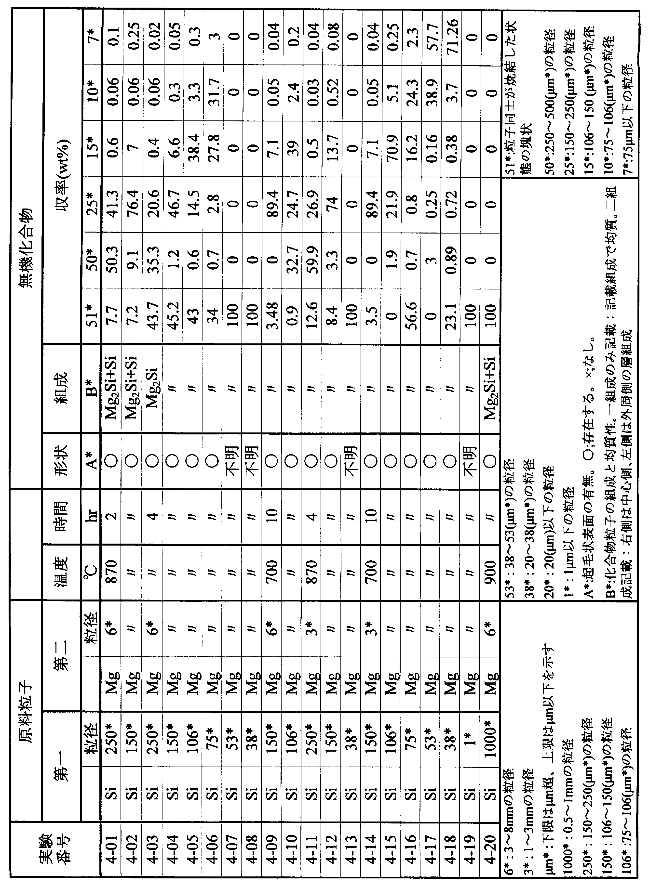
図20は、実験番号4-19で得られた化合物の写真である。この試験では、粒状でなく塊状の化合物が得られたことがわかる。
(実施例2)
Si(純度99.9999%)からなる第一原料粒子(Si粒子)と、Mg(純度99.9%以上)からなる第二原料粒子(Mg粒子)とを用意した。
Si粒子としては、粒径が106μmを超え150μm以下、75μmを超え106μm以下に分級した粒子を用意した。
Mg粒子としては、粒径約1~3mmの粒子を用意した。
添加元素として、粒径が75μmを超え250μm以下のアンチモン(Sb)粉末(純度99.99%)、粒径が約1~3mmのビスマス(Bi) 粒子(純度99.999%)、粒径が75μmを超え150μm以下のアルミニウム(Al)粒子(純度99.9%)を準備した。
これらの各粒子を、Mg2.02Si0.99Sb0.01、Mg2.02Si0.99Bi0.01、Mg2.01Al0.01Si0.99Sb0.01という組成の無機化合物が得られるように秤量した。
Si(純度99.9999%)からなる第一原料粒子(Si粒子)と、Mg(純度99.9%以上)からなる第二原料粒子(Mg粒子)とを用意した。
Si粒子としては、粒径が106μmを超え150μm以下、75μmを超え106μm以下に分級した粒子を用意した。
Mg粒子としては、粒径約1~3mmの粒子を用意した。
添加元素として、粒径が75μmを超え250μm以下のアンチモン(Sb)粉末(純度99.99%)、粒径が約1~3mmのビスマス(Bi) 粒子(純度99.999%)、粒径が75μmを超え150μm以下のアルミニウム(Al)粒子(純度99.9%)を準備した。
これらの各粒子を、Mg2.02Si0.99Sb0.01、Mg2.02Si0.99Bi0.01、Mg2.01Al0.01Si0.99Sb0.01という組成の無機化合物が得られるように秤量した。
図1に示すように、Mg粒子2を加熱容器10(カーボンボード)の底面に均一に敷き詰め、図2に示すように、Siおよび添加元素の粒子1(Si、Sb、Bi、Al)を、Mg粒子2を覆うようにMg粒子2上に配置した。加熱容器10を加熱炉内に収容し、0.1MPaのアルゴン-3%水素混合ガス雰囲気下で加熱処理を行った。加熱温度は800℃、加熱時間は4時間とした。
生成物について、目視による状態観察、ふるいによる分級、X線回折による相分析、走査型電子顕微鏡による形状・表面観察と組成分析を行った。結果を表5に示す。
図21は、化合物粒子の収率を示すグラフである。
この図に示すように、Sbを添加したMg2Si(組成式:Mg2Si0.99Sb0.01)からなる化合物粒子を得る実験番号5-01では、化合物粒子の収率は、粒径250μmを超え500μm以下が12.2%、150μmを超え250μm以下が26.7%、106μmを超え150μm以下では45.2%、75μmを超え106μm以下では7.1%、75μm以下では0.5%であった。
Bi添加したMg2Si(組成式:Mg2Si0.99Bi0.01)からなる化合物粒子を得る実験番号5-02では、化合物粒子の収率は、粒径250μmを超え500μm以下が12.5%、粒径150μmを超え250μm以下が23.9%、粒径106μmを超え150μm以下では50.1%、粒径75μmを超え106μm以下では5.4%、75μm以下では0.4%であった。
Sb添加の場合(実験番号5-01)とBi添加した場合(実験番号5-02)は、Si粒子径(75μmを超え106μm以下)が互いに同じであり、加熱処理条件も同じであるため、化合物粒子の収率も同程度の結果となった。
図21は、化合物粒子の収率を示すグラフである。
この図に示すように、Sbを添加したMg2Si(組成式:Mg2Si0.99Sb0.01)からなる化合物粒子を得る実験番号5-01では、化合物粒子の収率は、粒径250μmを超え500μm以下が12.2%、150μmを超え250μm以下が26.7%、106μmを超え150μm以下では45.2%、75μmを超え106μm以下では7.1%、75μm以下では0.5%であった。
Bi添加したMg2Si(組成式:Mg2Si0.99Bi0.01)からなる化合物粒子を得る実験番号5-02では、化合物粒子の収率は、粒径250μmを超え500μm以下が12.5%、粒径150μmを超え250μm以下が23.9%、粒径106μmを超え150μm以下では50.1%、粒径75μmを超え106μm以下では5.4%、75μm以下では0.4%であった。
Sb添加の場合(実験番号5-01)とBi添加した場合(実験番号5-02)は、Si粒子径(75μmを超え106μm以下)が互いに同じであり、加熱処理条件も同じであるため、化合物粒子の収率も同程度の結果となった。
SbとAlを添加したMg2Si(組成式:Mg1.99Al0.01Si0.99Bi0.01)からなる化合物粒子を得る実験番号5-03では、化合物粒子同士が結合した塊状物は21.8%、化合物粒子の収率は、粒径粒径250μmを超え500μm以下が26.8%、粒径150μmを超え250μm以下が44.8%、粒径106μmを超え150μm以下が6.1%、粒径75μmを超え106μm以下が0.3%、75μm以下では0.2%であった。
実験番号5-03は、実験番号5-01、5-02に比べてSi粒子径が大きいため(106μmを超え150μm以下)、化合物粒子の収率は、粒径150μmを超え250μm以下が最も高かった。
この結果より、MgおよびSi以外に第3元素(添加元素)を添加した場合には、簡便に化合物粒子が得られることがわかった。
実験番号5-03は、実験番号5-01、5-02に比べてSi粒子径が大きいため(106μmを超え150μm以下)、化合物粒子の収率は、粒径150μmを超え250μm以下が最も高かった。
この結果より、MgおよびSi以外に第3元素(添加元素)を添加した場合には、簡便に化合物粒子が得られることがわかった。

本発明により得られた無機化合物粒子は、軽量の構造材であるMg合金材への機械的強度を高めるための分散剤に使用できる。また、焼結体とした粒子は熱電材料として使用できる。
1 Si粒子(第一原料粒子)
2 Mg粒子(第二原料粒子)
2 Mg粒子(第二原料粒子)
Claims (8)
- 互いに異なる融点を持つ複数の元素を含む合成物である無機化合物粒子の製造方法であって、
前記複数の元素のうち、前記無機化合物の融点以上の融点を有する元素を含む第一原料粒子と、前記無機化合物の融点未満の融点を有する元素を含む第二原料粒子とを含む原材料を、前記両原料粒子を構成する前記元素の状態図上のII領域(液-固相領域)とI領域(固相領域)の共晶温度以上、かつ前記無機化合物の融点未満の温度で加熱することによって、前記第一原料粒子に第二原料粒子の溶融液を含浸させて、前記第一原料粒子内での前記両元素の合成反応により前記無機化合物粒子を得ることを特徴とする無機化合物粒子の製造方法。 - 請求項1に記載の無機化合物粒子の製造方法において、前記原材料は、前記第一原料粒子と前記第二原料粒子とを、前記無機化合物粒子における両者の主要元素割合に相当する原子割合で混合したものであることを特徴とする無機化合物粒子の製造方法。
- 請求項1または2に記載の無機化合物粒子の製造方法において、前記第一原料粒子の粒径は、20μmを超え500μm以下であり、合成後の前記無機化合物粒子の粒径が25μmを超え1mm以下であることを特徴とする無機化合物粒子の製造方法。
- 請求項1から3のいずれかに記載の無機化合物粒子の製造方法において、前記第一原料粒子は、相互に異なる元素からなる複数種類の粒子の混合物であることを特徴とする無機化合物粒子の製造方法。
- 請求項1から3のいずれかに記載の無機化合物粒子の製造方法において、前記第一原料粒子は、相互に異なる元素からなる複数種類の粒子の合成物であることを特徴とする無機化合物粒子の製造方法。
- 請求項1から5のいずれかに記載の無機化合物粒子の製造方法で得られた無機化合物粒子であって、その粒径に比べて微小な突起が起毛状に表面を覆っていることを特徴とする無機化合物粒子。
- 請求項6に記載の無機化合物粒子において、中心部が前記第一原料粒子を構成する元素を主たる構成元素とし、外周部が前記第二原料粒子を構成する元素を主たる構成元素とする二層構造を有していることを特徴とする無機化合物粒子。
- 請求項6に記載の無機化合物粒子において、その外周から中心部まで均一な組成であることを特徴とする無機化合物粒子。
Priority Applications (2)
| Application Number | Priority Date | Filing Date | Title |
|---|---|---|---|
| EP12762958.2A EP2690064B1 (en) | 2011-03-25 | 2012-03-23 | Inorganic-compound particles and process for producing same |
| US14/142,199 US9340431B2 (en) | 2011-03-25 | 2013-12-27 | Inorganic-compound particles and process for producing same |
Applications Claiming Priority (2)
| Application Number | Priority Date | Filing Date | Title |
|---|---|---|---|
| JP2011-068559 | 2011-03-25 | ||
| JP2011068559A JP5773341B2 (ja) | 2011-03-25 | 2011-03-25 | 無機化合物粒子およびその製造方法 |
Related Child Applications (2)
| Application Number | Title | Priority Date | Filing Date |
|---|---|---|---|
| US14005978 A-371-Of-International | 2012-03-23 | ||
| US14/142,199 Continuation US9340431B2 (en) | 2011-03-25 | 2013-12-27 | Inorganic-compound particles and process for producing same |
Publications (1)
| Publication Number | Publication Date |
|---|---|
| WO2012133176A1 true WO2012133176A1 (ja) | 2012-10-04 |
Family
ID=46930899
Family Applications (1)
| Application Number | Title | Priority Date | Filing Date |
|---|---|---|---|
| PCT/JP2012/057497 Ceased WO2012133176A1 (ja) | 2011-03-25 | 2012-03-23 | 無機化合物粒子およびその製造方法 |
Country Status (3)
| Country | Link |
|---|---|
| EP (1) | EP2690064B1 (ja) |
| JP (1) | JP5773341B2 (ja) |
| WO (1) | WO2012133176A1 (ja) |
Cited By (2)
| Publication number | Priority date | Publication date | Assignee | Title |
|---|---|---|---|---|
| JP2015020917A (ja) * | 2013-07-16 | 2015-02-02 | 三井化学株式会社 | シラン類の製造方法 |
| US9722259B2 (en) | 2013-08-21 | 2017-08-01 | Murata Manufacturing Co., Ltd. | Ceramic substrate for electrochemical element, manufacturing method therefore, fuel cell, and fuel cell stack |
Families Citing this family (5)
| Publication number | Priority date | Publication date | Assignee | Title |
|---|---|---|---|---|
| JP6211248B2 (ja) * | 2012-03-30 | 2017-10-11 | 学校法人五島育英会 | MgAlB14系の熱電材料 |
| EP2913857B1 (en) | 2012-11-27 | 2017-05-24 | Yasunaga Corporation | Mg-Si THERMOELECTRIC CONVERSION MATERIAL, METHOD FOR PRODUCING SAME, SINTERED BODY FOR THERMOELECTRIC CONVERSION, THERMOELECTRIC CONVERSION ELEMENT, AND THERMOELECTRIC CONVERSION MODULE |
| JP6370595B2 (ja) * | 2013-04-30 | 2018-08-08 | 地方独立行政法人東京都立産業技術研究センター | マグネシウム粉末冶金焼結体の製造方法、そのマグネシウム粉末冶金焼結体およびマグネシウム粉末冶金材料 |
| JP6377519B2 (ja) * | 2014-12-24 | 2018-08-22 | 古河機械金属株式会社 | 熱電変換材料の製造方法 |
| JP7251187B2 (ja) * | 2018-02-27 | 2023-04-04 | 三菱マテリアル株式会社 | 熱電変換材料、熱電変換素子、熱電変換モジュール、及び、熱電変換材料の製造方法 |
Citations (1)
| Publication number | Priority date | Publication date | Assignee | Title |
|---|---|---|---|---|
| WO2004016375A1 (ja) * | 2002-08-14 | 2004-02-26 | Toudai Tlo, Ltd. | マグネシウム化合物、マグネシウム化合物被膜、マグネシウム合金材料、金属材料およびそれらの製造方法 |
Family Cites Families (6)
| Publication number | Priority date | Publication date | Assignee | Title |
|---|---|---|---|---|
| JP3824670B2 (ja) * | 1994-10-25 | 2006-09-20 | 虹技株式会社 | 成形用固液共存金属の製造方法 |
| JP2002285274A (ja) * | 2001-03-27 | 2002-10-03 | Daido Steel Co Ltd | Mg−Si系熱電材料及びその製造方法 |
| JP2002368291A (ja) * | 2001-06-04 | 2002-12-20 | Tokyo Yogyo Co Ltd | 熱電材料 |
| JP2009094497A (ja) * | 2007-09-18 | 2009-04-30 | Toyota Industries Corp | p型熱電材料及びその製造方法 |
| JP2011040506A (ja) * | 2009-08-07 | 2011-02-24 | Toyota Industries Corp | p型熱電材料及びその製造方法 |
| CN101850977B (zh) * | 2010-05-19 | 2011-04-20 | 南京亚格泰新能源材料有限公司 | 一种硅化镁反应炉 |
-
2011
- 2011-03-25 JP JP2011068559A patent/JP5773341B2/ja active Active
-
2012
- 2012-03-23 WO PCT/JP2012/057497 patent/WO2012133176A1/ja not_active Ceased
- 2012-03-23 EP EP12762958.2A patent/EP2690064B1/en active Active
Patent Citations (1)
| Publication number | Priority date | Publication date | Assignee | Title |
|---|---|---|---|---|
| WO2004016375A1 (ja) * | 2002-08-14 | 2004-02-26 | Toudai Tlo, Ltd. | マグネシウム化合物、マグネシウム化合物被膜、マグネシウム合金材料、金属材料およびそれらの製造方法 |
Non-Patent Citations (3)
| Title |
|---|
| NISHIDA I ET AL.: "Thermoelectric conversion engineering, Fundamentals and Applications", 30 May 2001, REALIZE SCIENCE & ENGINEERING CENTER |
| See also references of EP2690064A4 |
| YUKIHIRO ISODA ET AL.: "Fabrication and Thermoelectric Properties on Silicides Thermoelectric Materials with Eco-friendly", CERAMICS, vol. 40, no. 7, 2005, pages 534 - 537, XP008172333 * |
Cited By (2)
| Publication number | Priority date | Publication date | Assignee | Title |
|---|---|---|---|---|
| JP2015020917A (ja) * | 2013-07-16 | 2015-02-02 | 三井化学株式会社 | シラン類の製造方法 |
| US9722259B2 (en) | 2013-08-21 | 2017-08-01 | Murata Manufacturing Co., Ltd. | Ceramic substrate for electrochemical element, manufacturing method therefore, fuel cell, and fuel cell stack |
Also Published As
| Publication number | Publication date |
|---|---|
| EP2690064B1 (en) | 2019-05-15 |
| EP2690064A4 (en) | 2015-03-18 |
| JP2012201937A (ja) | 2012-10-22 |
| EP2690064A1 (en) | 2014-01-29 |
| JP5773341B2 (ja) | 2015-09-02 |
Similar Documents
| Publication | Publication Date | Title |
|---|---|---|
| JP5773341B2 (ja) | 無機化合物粒子およびその製造方法 | |
| Krasnowski et al. | Nanocrystalline Al–Fe intermetallics–light weight alloys with high hardness | |
| Tavoosi et al. | Bulk Al–Zn/Al2O3 nanocomposite prepared by reactive milling and hot pressing methods | |
| CN104532068B (zh) | 纳米TiC陶瓷颗粒增强铝基复合材料及其制备方法 | |
| US20170130299A1 (en) | Method for manufacturing copper alloy and copper alloy | |
| CN105328186A (zh) | 一种基于激光3d打印形成的铝基原位复合材料及其制备方法 | |
| WO2012005323A1 (ja) | クラスレート化合物および熱電変換材料ならびに熱電変換材料の製造方法 | |
| WO2016039372A1 (ja) | 熱電変換材料、熱電変換材料の製造方法および熱電変換モジュール | |
| JP6342916B2 (ja) | Al/TiCナノコンポジット材料を製造する方法 | |
| EP3730231B1 (en) | Powder material, use of powder material for additive manufacturing, and method for producing powder material | |
| WO2014014126A1 (ja) | 熱電変換材料およびそれを用いた熱電変換モジュール並びに熱電変換材料の製造方法 | |
| TW201103999A (en) | Method for manufacturing nickel alloy target | |
| JP2016219666A (ja) | 熱電材料及びその製造方法 | |
| JP2011243729A (ja) | 異方性熱電変換ナノ粒子の製造方法およびそれを用いた異方性熱電変換焼結体の製造方法 | |
| KR102010307B1 (ko) | 알루미늄-티타늄 복합재료의 제조방법 및 이에 의해 제조된 알루미늄-티타늄 복합재료 | |
| US20160245450A1 (en) | Heat insulating material | |
| JP5974821B2 (ja) | ナノコンポジット熱電変換材料およびその製造方法 | |
| Kumar et al. | Hierarchical nano-/micro-architecture phonon scattering of p-type Bismuth telluride bulk composites with Ag-TiO2 nano particles synthesized by fluidized bed spray coating method | |
| JP7713897B2 (ja) | スパッタリングターゲット及びその製造方法 | |
| Hsu et al. | Effects of the Zr0. 5Hf0. 5FexCo1− xSb0. 8Sn0. 2/Fe3Sn2 half-Heusler composites on the ZT value | |
| CN112143929B (zh) | 一种Al-Mg合金线的石墨烯负载晶粒细化材料及其制备方法 | |
| US9340431B2 (en) | Inorganic-compound particles and process for producing same | |
| KR101892394B1 (ko) | Bi-Te계 소결합금 제조방법 및 이를 이용한 Bi-Te계 소결합금 | |
| JP2016223012A (ja) | スパッタリングターゲット | |
| JP6155141B2 (ja) | 熱電変換材料およびその製造方法 |
Legal Events
| Date | Code | Title | Description |
|---|---|---|---|
| 121 | Ep: the epo has been informed by wipo that ep was designated in this application |
Ref document number: 12762958 Country of ref document: EP Kind code of ref document: A1 |
|
| NENP | Non-entry into the national phase |
Ref country code: DE |
|
| WWE | Wipo information: entry into national phase |
Ref document number: 2012762958 Country of ref document: EP |