WO2012133566A1 - 二次電池用電極材料、二次電池用電極材料の製造方法および二次電池 - Google Patents
二次電池用電極材料、二次電池用電極材料の製造方法および二次電池 Download PDFInfo
- Publication number
- WO2012133566A1 WO2012133566A1 PCT/JP2012/058203 JP2012058203W WO2012133566A1 WO 2012133566 A1 WO2012133566 A1 WO 2012133566A1 JP 2012058203 W JP2012058203 W JP 2012058203W WO 2012133566 A1 WO2012133566 A1 WO 2012133566A1
- Authority
- WO
- WIPO (PCT)
- Prior art keywords
- ion conductive
- layer
- cation
- secondary battery
- electrode material
- Prior art date
- Legal status (The legal status is an assumption and is not a legal conclusion. Google has not performed a legal analysis and makes no representation as to the accuracy of the status listed.)
- Ceased
Links
Images


Classifications
-
- H—ELECTRICITY
- H01—ELECTRIC ELEMENTS
- H01M—PROCESSES OR MEANS, e.g. BATTERIES, FOR THE DIRECT CONVERSION OF CHEMICAL ENERGY INTO ELECTRICAL ENERGY
- H01M4/00—Electrodes
- H01M4/02—Electrodes composed of, or comprising, active material
- H01M4/36—Selection of substances as active materials, active masses, active liquids
- H01M4/58—Selection of substances as active materials, active masses, active liquids of inorganic compounds other than oxides or hydroxides, e.g. sulfides, selenides, tellurides, halogenides or LiCoFy; of polyanionic structures, e.g. phosphates, silicates or borates
-
- H—ELECTRICITY
- H01—ELECTRIC ELEMENTS
- H01M—PROCESSES OR MEANS, e.g. BATTERIES, FOR THE DIRECT CONVERSION OF CHEMICAL ENERGY INTO ELECTRICAL ENERGY
- H01M4/00—Electrodes
- H01M4/02—Electrodes composed of, or comprising, active material
- H01M4/13—Electrodes for accumulators with non-aqueous electrolyte, e.g. for lithium-accumulators; Processes of manufacture thereof
- H01M4/131—Electrodes based on mixed oxides or hydroxides, or on mixtures of oxides or hydroxides, e.g. LiCoOx
-
- C—CHEMISTRY; METALLURGY
- C01—INORGANIC CHEMISTRY
- C01B—NON-METALLIC ELEMENTS; COMPOUNDS THEREOF; METALLOIDS OR COMPOUNDS THEREOF NOT COVERED BY SUBCLASS C01C
- C01B25/00—Phosphorus; Compounds thereof
- C01B25/16—Oxyacids of phosphorus; Salts thereof
- C01B25/26—Phosphates
- C01B25/45—Phosphates containing plural metal, or metal and ammonium
-
- C—CHEMISTRY; METALLURGY
- C01—INORGANIC CHEMISTRY
- C01B—NON-METALLIC ELEMENTS; COMPOUNDS THEREOF; METALLOIDS OR COMPOUNDS THEREOF NOT COVERED BY SUBCLASS C01C
- C01B32/00—Carbon; Compounds thereof
- C01B32/05—Preparation or purification of carbon not covered by groups C01B32/15, C01B32/20, C01B32/25, C01B32/30
-
- H—ELECTRICITY
- H01—ELECTRIC ELEMENTS
- H01M—PROCESSES OR MEANS, e.g. BATTERIES, FOR THE DIRECT CONVERSION OF CHEMICAL ENERGY INTO ELECTRICAL ENERGY
- H01M10/00—Secondary cells; Manufacture thereof
- H01M10/05—Accumulators with non-aqueous electrolyte
- H01M10/052—Li-accumulators
-
- H—ELECTRICITY
- H01—ELECTRIC ELEMENTS
- H01M—PROCESSES OR MEANS, e.g. BATTERIES, FOR THE DIRECT CONVERSION OF CHEMICAL ENERGY INTO ELECTRICAL ENERGY
- H01M4/00—Electrodes
- H01M4/02—Electrodes composed of, or comprising, active material
- H01M4/04—Processes of manufacture in general
- H01M4/0471—Processes of manufacture in general involving thermal treatment, e.g. firing, sintering, backing particulate active material, thermal decomposition, pyrolysis
-
- H—ELECTRICITY
- H01—ELECTRIC ELEMENTS
- H01M—PROCESSES OR MEANS, e.g. BATTERIES, FOR THE DIRECT CONVERSION OF CHEMICAL ENERGY INTO ELECTRICAL ENERGY
- H01M4/00—Electrodes
- H01M4/02—Electrodes composed of, or comprising, active material
- H01M4/13—Electrodes for accumulators with non-aqueous electrolyte, e.g. for lithium-accumulators; Processes of manufacture thereof
- H01M4/136—Electrodes based on inorganic compounds other than oxides or hydroxides, e.g. sulfides, selenides, tellurides, halogenides or LiCoFy
-
- H—ELECTRICITY
- H01—ELECTRIC ELEMENTS
- H01M—PROCESSES OR MEANS, e.g. BATTERIES, FOR THE DIRECT CONVERSION OF CHEMICAL ENERGY INTO ELECTRICAL ENERGY
- H01M4/00—Electrodes
- H01M4/02—Electrodes composed of, or comprising, active material
- H01M4/13—Electrodes for accumulators with non-aqueous electrolyte, e.g. for lithium-accumulators; Processes of manufacture thereof
- H01M4/139—Processes of manufacture
- H01M4/1397—Processes of manufacture of electrodes based on inorganic compounds other than oxides or hydroxides, e.g. sulfides, selenides, tellurides, halogenides or LiCoFy
-
- H—ELECTRICITY
- H01—ELECTRIC ELEMENTS
- H01M—PROCESSES OR MEANS, e.g. BATTERIES, FOR THE DIRECT CONVERSION OF CHEMICAL ENERGY INTO ELECTRICAL ENERGY
- H01M4/00—Electrodes
- H01M4/02—Electrodes composed of, or comprising, active material
- H01M4/36—Selection of substances as active materials, active masses, active liquids
- H01M4/362—Composites
- H01M4/366—Composites as layered products
-
- H—ELECTRICITY
- H01—ELECTRIC ELEMENTS
- H01M—PROCESSES OR MEANS, e.g. BATTERIES, FOR THE DIRECT CONVERSION OF CHEMICAL ENERGY INTO ELECTRICAL ENERGY
- H01M4/00—Electrodes
- H01M4/02—Electrodes composed of, or comprising, active material
- H01M4/36—Selection of substances as active materials, active masses, active liquids
- H01M4/38—Selection of substances as active materials, active masses, active liquids of elements or alloys
-
- H—ELECTRICITY
- H01—ELECTRIC ELEMENTS
- H01M—PROCESSES OR MEANS, e.g. BATTERIES, FOR THE DIRECT CONVERSION OF CHEMICAL ENERGY INTO ELECTRICAL ENERGY
- H01M4/00—Electrodes
- H01M4/02—Electrodes composed of, or comprising, active material
- H01M4/36—Selection of substances as active materials, active masses, active liquids
- H01M4/58—Selection of substances as active materials, active masses, active liquids of inorganic compounds other than oxides or hydroxides, e.g. sulfides, selenides, tellurides, halogenides or LiCoFy; of polyanionic structures, e.g. phosphates, silicates or borates
- H01M4/5825—Oxygenated metallic salts or polyanionic structures, e.g. borates, phosphates, silicates, olivines
-
- H—ELECTRICITY
- H01—ELECTRIC ELEMENTS
- H01M—PROCESSES OR MEANS, e.g. BATTERIES, FOR THE DIRECT CONVERSION OF CHEMICAL ENERGY INTO ELECTRICAL ENERGY
- H01M4/00—Electrodes
- H01M4/02—Electrodes composed of, or comprising, active material
- H01M4/36—Selection of substances as active materials, active masses, active liquids
- H01M4/58—Selection of substances as active materials, active masses, active liquids of inorganic compounds other than oxides or hydroxides, e.g. sulfides, selenides, tellurides, halogenides or LiCoFy; of polyanionic structures, e.g. phosphates, silicates or borates
- H01M4/583—Carbonaceous material, e.g. graphite-intercalation compounds or CFx
- H01M4/587—Carbonaceous material, e.g. graphite-intercalation compounds or CFx for inserting or intercalating light metals
-
- H—ELECTRICITY
- H01—ELECTRIC ELEMENTS
- H01M—PROCESSES OR MEANS, e.g. BATTERIES, FOR THE DIRECT CONVERSION OF CHEMICAL ENERGY INTO ELECTRICAL ENERGY
- H01M4/00—Electrodes
- H01M4/02—Electrodes composed of, or comprising, active material
- H01M4/62—Selection of inactive substances as ingredients for active masses, e.g. binders, fillers
- H01M4/624—Electric conductive fillers
- H01M4/625—Carbon or graphite
-
- Y—GENERAL TAGGING OF NEW TECHNOLOGICAL DEVELOPMENTS; GENERAL TAGGING OF CROSS-SECTIONAL TECHNOLOGIES SPANNING OVER SEVERAL SECTIONS OF THE IPC; TECHNICAL SUBJECTS COVERED BY FORMER USPC CROSS-REFERENCE ART COLLECTIONS [XRACs] AND DIGESTS
- Y02—TECHNOLOGIES OR APPLICATIONS FOR MITIGATION OR ADAPTATION AGAINST CLIMATE CHANGE
- Y02E—REDUCTION OF GREENHOUSE GAS [GHG] EMISSIONS, RELATED TO ENERGY GENERATION, TRANSMISSION OR DISTRIBUTION
- Y02E60/00—Enabling technologies; Technologies with a potential or indirect contribution to GHG emissions mitigation
- Y02E60/10—Energy storage using batteries
Definitions
- the present invention relates to an electrode material for a secondary battery used for a lithium ion secondary battery, a manufacturing method thereof, and a secondary battery using the electrode material for the secondary battery.
- lithium cobaltate LiCoO 2
- LiMn 2 O 4 lithium manganate
- LiNiO 2 lithium nickelate
- lithium transition metal compounds such as lithium iron phosphate (LiFePO 4 ).
- the lithium iron phosphate is a positive electrode material having an olivine type crystal structure.
- the positive electrode material having an olivine type crystal structure has a chemical formula represented by LiMPO 4 , and M is a transition metal such as manganese (Mn), cobalt (Co), nickel (Ni), etc. in addition to the iron (Fe).
- the LiMPO 4 has a large theoretical capacity when used as a positive electrode material (for example, 170 mAh / g in the case of lithium iron phosphate), and a relatively high electromotive force [in the case of lithium iron phosphate, as opposed to Li / Li + negative electrode. About 3.4 to 3.5 V, and about 4.1 V for lithium manganese phosphate (LiMnPO 4 ). Furthermore, it is thermodynamically stable (in the case of lithium iron phosphate, there is almost no oxygen release or heat generation up to about 400 ° C.), and it can be said that it is a preferable positive electrode material from the viewpoint of safety.
- lithium iron phosphate and lithium manganese phosphate are expected to be promising positive electrode materials because they can be produced at low cost from resource-rich iron, manganese, phosphorus, and the like.
- the lithium iron phosphate has low conductivity (conductivity ⁇ ⁇ 10 ⁇ 8 S / cm at 25 ° C.) and low lithium ion diffusivity (diffusion coefficient D ⁇ 10 ⁇ 13 at 25 ° C.). cm about 2 / s) for not good output characteristic is obtained in this state.
- lithium manganese phosphate is estimated to be several orders of magnitude lower than lithium iron phosphate in both conductivity and self-diffusion coefficient.
- the low diffusibility of lithium ions is also derived from the crystal structure of the electrode active material having an olivine type crystal structure (orthorhombic system, space group Pnma).
- the olivine-type electrode active material has a space group Pnma type crystal lattice structure as shown in FIG. 3, and a cation such as Li, Na, Mg, etc. connects the lithium ion sites in the crystal b-axis direction inside the crystal lattice. It has a structure that can move only in the allowable movement direction in the original tunnel. Therefore, it is known that the degree of freedom of ion diffusion is low because the movement direction of the cation is limited to only one direction.
- Patent Document 1 proposes a technique in which a carbon precursor that generates conductive carbon by thermal decomposition is used, and the conductive carbon is coated on the particle surface of an electrode material such as lithium iron phosphate by thermal decomposition.
- Patent Document 1 describes that the conductive carbon coating imparts sufficient electronic conductivity as an electrode material, but describes measures for improving the low degree of freedom of lithium ion diffusion described above. It has not been.
- Patent Document 2 discloses an electrode material in which a lithium ion conductive material layer is coated on the surface of the olivine-based electrode active material particles having the one-dimensional ion diffusibility. Patent Document 2 describes that the lithium ion conductive material layer improves the degree of freedom of lithium ion diffusion and improves output characteristics, but mentions the conductive carbon coating of active material particles. Not.
- Figures 12C-12E are disclosed. There, values of about 135 mAh / g and over 100 mAh / g are shown as initial discharge capacities at 44C and 60C, respectively.
- Patent Document 2 Although the rate characteristics of the above-described lithium ion conductive layer-coated positive electrode material are considered to be very high at first glance, the conductive auxiliary agent in the positive electrode mixture commonly used in charge and discharge tests. There are almost no important measurement conditions such as the ratio of addition in the literature, and accurate evaluation cannot be made.
- Non-Patent Document 1 by the same author as the inventor of Patent Document 2 describes amorphous lithium ion conduction obtained by solid-phase firing under almost the same conditions except that the firing temperature is 600 ° C.
- a layer-coated lithium iron phosphate cathode material is disclosed and its discharge rate characteristics up to 50C and up to about 200C are shown.
- the discharge rate characteristic up to 60 C in the above-mentioned Patent Document 2 is close to that up to 50 C in Non-Patent Document 1, and it is surmised that the measurement conditions of both were the same.
- Patent Document 3 discloses an electrode material produced by mixing an active material whose surface is covered with a lithium ion conductive polymer and an electronic conductive agent.
- a lithium ion conductive polymer is partially coated on the surface of an active material, and a conductive agent or a conductive agent and a lithium ion conductive inorganic solid are coated on a portion not covered with the lithium ion conductive polymer.
- An electrode material that is partially or fully coated with an electrolyte is disclosed.
- Patent Document 5 discloses an electrode material provided with a coating layer containing a conductive agent and a lithium ion conductive inorganic solid electrolyte on the surface of an active material.
- Patent Documents 3 to 5 are all intended to improve the decrease in charge / discharge capacity caused by the expansion and contraction of the active material accompanying the charge / discharge of the lithium secondary battery. It was not made for the purpose of improving the low conductivity of the active material itself and the freedom of diffusion of low lithium ions, and there is no description of the effects corresponding to these.
- the object of the present invention is the problem of one-dimensional diffusivity and low ion diffusibility of lithium ions derived from the crystal structure, such as lithium iron phosphate and lithium manganese phosphate, and low conductivity.
- the electrode material for a secondary battery according to the first aspect of the present invention releases or occludes a cation of a monovalent or divalent metal in association with electrochemical oxidation or reduction, and
- the crystalline primary particles of the electrode active material in which the cations can move only in the one-dimensional permissible movement direction within the crystal lattice, the ion conductive material coexisting on the surface of the primary particles, and the carbon precursor are heated.
- Conductive ions generated by decomposition, and the ion conductive substance has a property of allowing movement of the cations in two dimensions or three dimensions, and the cations are the coexisting ions.
- the coexisting layer of the ion conductive material and the conductive carbon may not cover the entire surface of the primary particles. It is sufficient to cover at least 50% of the entire surface. In the case of 50% or more, it is preferable that the primary particles are scattered evenly on the surface.
- the ion conductive substance has a property of allowing the movement of the cation in two dimensions or three dimensions, the degree of freedom in the movement direction of the cation is thereby improved. Furthermore, since the cation can move through the coexisting layer of the ion conductive material and the conductive carbon, the cation transfer path can be secured to improve the ion conductivity, and the conductive carbon can improve the electron conductivity. Conductivity is obtained. Therefore, it becomes easy for lithium ions to pass during charge / discharge when the secondary battery is formed, and the charge / discharge utilization rate and rate characteristics of the electrode active material are improved.
- the total thickness of the coexisting layer of the ion conductive material and the conductive carbon is about 1 to 30 nm, preferably about 1 to 10 nm as a whole.
- the electrode material for a secondary battery according to the second aspect of the present invention releases or occludes a monovalent or divalent metal cation during electrochemical oxidation or reduction, and in the process of oxidation or reduction, a crystal lattice
- the crystal primary particles of the electrode active material in which the cation can move only in the one-dimensional allowable movement direction inside, the ion conductive material layer present on at least a part of the surface of the primary particles, and the carbon precursor are pyrolyzed
- the cation is configured to be movable through the ion conductive material layer and the conductive carbon layer.
- the ratio of “at least a part” in “the ion conductive material layer existing on at least a part of the surface of the primary particle” is preferably 50% or more of the entire surface. In the case of 50% or more, it is preferable that the primary particles are scattered evenly on the surface. According to this aspect, substantially the same effect as the first aspect can be obtained.
- the electrode material for a secondary battery according to the third aspect of the present invention releases or occludes a monovalent or divalent metal cation during electrochemical oxidation or reduction, and in the process of oxidation or reduction, a crystal lattice
- the crystal primary particles of the electrode active material in which the cation can move only in the one-dimensional allowable movement direction inside, the ion conductive material layer present on at least a part of the surface of the primary particles, and the carbon precursor are pyrolyzed
- the conductive carbon layer has a passage hole through which the cation can pass in the thickness direction of the conductive carbon layer, and the end of the primary particle intersecting the allowable movement direction of the cation.
- the passage hole of the conductive carbon layer is characterized in that the is configured to be connected via an ion-conducting material layer.
- the ion conductive material layer existing on at least a part of the surface of the primary particle means that the ion conductive material layer covers the entire surface of the primary particle and a part of the surface of the primary particle. It is used to include both configurations.
- a conductive carbon layer existing at least on a part of the surface of the ion conductive material layer means a conductive carbon layer only on the surface of the ion conductive material layer.
- the conductive carbon layer is also present on the surface of the electrode active material in which the ion conductive material layer is not present.
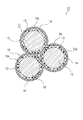
- the electrode material (reference numeral 1) for the secondary battery shown in FIG. 1 includes primary particles of the electrode active material (reference numeral 2) and an ion conductive material layer (reference numeral 3) that covers the surfaces of the primary particles of the electrode active material. And a conductive carbon layer (reference numeral 4) for further covering the ion conductive material layer.
- the electrode active material 2 releases or occludes a cation of a monovalent or divalent metal during electrochemical oxidation or reduction, and one-dimensional permissible movement inside the crystal lattice during the oxidation or reduction process. It has a crystal structure in which the cation can move only in the direction (symbol 6). That is, the cations are released or occluded only from the two end faces (symbol 7) that intersect the allowable movement direction of the cations in the electrode active material.
- the surface of the primary particle of such an electrode active material is provided so that the said ion conductive material layer may coat
- the ion conductive material layer has sufficient ion conductivity of the cation with respect to charge and discharge of the electrode active material. Further, the ion conductive material layer has a property of allowing movement of the cation in two or three dimensions. Since the ion conductive material layer covers the end surface of the primary particle intersecting the allowable movement direction of the cation, cations released from the end surface are taken into the ion conductive material layer, and the ion conductive material In the material layer, two-dimensional or three-dimensional internal movement is possible. As a result, the cations are released from anywhere on the surface of the ion conductive material layer.
- the conductive carbon layer covering the ion conductive material layer has sufficient conductivity for charging and discharging the electrode active material, and can pass the cations in the thickness direction of the conductive carbon layer. It has a hole. As described above, since the cations released from the end face freely move in the ion conductive material layer, the cations taken into the ion conductive material layer can reach the passage hole. Then, the cations are released through the passage holes, and an ion conduction path is created with an external electrolyte (electrolytic solution, solid electrolyte, etc.) in contact with the electrode material. The occlusion of cations by the electrode active material may follow the reverse movement path of the release process.
- electrolyte electrolytelectrolytic solution, solid electrolyte, etc.
- the conductive carbon layer can provide good electronic conductivity and can secure a cation movement path, thereby improving the ionic conductivity. Therefore, it becomes easy for lithium ions to pass during charge / discharge when the secondary battery is formed, and the charge / discharge utilization rate and rate characteristics of the electrode active material are improved.
- the ion conductive material layer 3 covers the entire surface of the primary particles of the electrode active material 2, but the ion conductive material is present on the primary particle surface of the electrode active material 2 other than the end face 7. There may be a portion not covered with the layer 3. At least a part of the end surface 7 of the primary particle of the electrode active material 2 intersecting the allowable movement direction 6 of the cation 5 is covered with the ion conductive material layer 3, and the end surface 7 and the conductive carbon layer 4 pass through.
- a hole 8 is configured to be connected via the ion conductive material layer 3, and the cation 5 moves in the ion conductive material layer 3 and passes through the through hole 8 in the immediate vicinity of the end surface 7. If it passes, an ion conduction path is formed between the external electrolyte (electrolytic solution, solid electrolyte, etc.) and the electrode material 1, and the charge / discharge utilization rate and rate characteristics of the electrode active material 2 are improved.
- the portion not covered with the ion conductive material layer 3 may be directly covered with the conductive carbon layer 4. That is, it is formed by thermally decomposing an ion conductive material layer 3 present on at least a part of the surface of the primary particles of the electrode active material 2, and at least a surface of the ion conductive material layer 3. Any structure may be used as long as it includes the conductive carbon layer 4 present in part and the ion conduction path is formed.
- the electrode active material in any one of the embodiments of the third aspect the first embodiment, the electrode active material, a material represented by the general formula Amdo 4 In the above general formula AMDO 4 , A is a cation and any one or a combination of Li, Na and Mg, and M is Fe, Mn, Co and Ni.
- D includes P or P and Al, Si, S, V and Any one or more of Mo It is combined, and is characterized in that the electrical neutrality is maintained as a whole the Amdo 4.
- the general formula AMDO 4 has, for example, an olivine type crystal structure (orthorhombic system, space group Pnma) represented by a general formula Li a MPO 4 including LiMPO 4 (where a is a positive number of 1 or less).
- M in the general formula is a transition metal such as iron, manganese, cobalt, nickel, or a plurality of combinations thereof.
- the general formula AMDO 4 is represented by, for example, the general formula A a M ′ 1-x M ′′ x P 1-y Y y O 4 having the olivine type crystal structure in addition to the Li a MPO 4.
- An electrode active material containing a crystalline compound as a main component can be used, where A is a cation and any one or a combination of Li, Na, and Mg.
- M in formula AMDO 4 may be M ′ 1-x M ′′ x , where M ′ is any one or a combination of Fe, Mn, Co and Ni, and M ′′ is Mg, Ca, Sc, Ti, Zr, V, Nb, Cr, Mo, W, Cu, Zn, Al, Ga, In and Sn are any one or a combination.
- D of general formula AMDO 4 may be comprised by P (phosphorus) and Y mentioned later.
- Y is any one or a combination of Al, Si, S, V and Mo, x and y are 0 or more and 0.4 or less, and one of them is a non-zero number, and a Is a positive number of 1 or less, and is selected so that the compound retains electrical neutrality.
- the cation is a Li ion
- the electrode active material is a general formula Li
- An example of a desirable embodiment is that a compound represented by a (Fe 1-xz Mn z ) M ′′ x PO 4 (where z is a number from 0 to 1-x) as a main component is included. It is done.
- the electrode material for a secondary battery according to a fifth aspect of the present invention is the electrode material for a secondary battery according to the fourth aspect, wherein the ion conductive substance layer includes an oxoacid salt layer containing at least A and D in the AMDO 4 , It has a cation conductivity function of a cation.
- a preferred example of the ion conductive material layer in this embodiment is an oxo acid salt layer containing A and D, in which the conductive (electron) electron is maintained while maintaining the ion conductive function of the cation.
- M is included in a state where conductivity is also imparted.
- the M is included in a state where the M is replaced with a part of the A in the ion conductive material layer.
- the ion conductive material layer including A and D or A, D and M is at least partially in an amorphous state.
- the electrode active material AMDO 4 is LiFePO 4 having an olivine structure
- a preferred example of the ion conductive layer material layer is Li 4 as a (poly) phosphate containing A and D in the AMDO 4 .
- P 2 O 7 or Li 3 PO 4 or compounds having an intermediate composition thereof are included.
- / or trivalent Fe is included in a state where the Li 4 P 2 O 7 or Li 3 PO 4 , or a part of Li in the compound having an intermediate composition thereof is substituted.
- the ion conductive layer material layer includes, for example, at least one of compounds having the following composition: Li 3-2x Fe (II) x PO 4 , Li 2-2x Fe (II) x P 2 O 7 , Li 3-3x Fe (III) x PO 4 , Li 2-3x Fe (III) x P 2 O 7 , Li 9-4x Fe (II) 2x (PO 4 ) 3 , Li 9-6x Fe (III) 2x (PO 4 ) 3
- x is a positive number of 1 or less, preferably about 0.3 or less
- the coefficient of Li is a positive number.
- the ion conductive material layer is preferably at least partially in an amorphous state.
- the electrode material of the fourth aspect has suitable ion conductivity. Further, in a preferable embodiment including M, the ion conductive material layer also has good ion conductivity and conductivity (electron conductivity). With these effects, a charge / discharge utilization rate and rate characteristics suitable as an electrode material for a secondary battery can be obtained.
- the electrode material for a secondary battery according to the sixth aspect of the present invention is the electrode material for forming the ion conductive material layer according to any one of the first to fifth aspects, (A) One kind selected from the group of oxides, sulfides, phosphates, silicates, and nitrides containing monovalent or divalent metal cations, or (B) from the group (A) It is a composite of a plurality of selected substances.
- a monovalent or divalent metal as the ion conductive substance (FIG. 1).
- the ion conductive material layer has an amorphous structure at least partially. It is characterized by having.
- the ion conductive material layer has an amorphous structure at least in part, so that the ion conductivity The adhesion between the material layer and the electrode active material particles is increased. Furthermore, since a substance having an amorphous structure is generally isotropic in ion diffusion, it is possible to impart three-dimensional ion conductivity of the cation to the ion conductive substance layer.
- the electrode material for a secondary battery according to an eighth aspect of the present invention is the electrode material for a secondary battery according to any one of the first aspect to the seventh aspect, wherein the molar distribution of the cation in the electrode active material and the ion
- the value of the ratio with the molar distribution of the cation in the conductive material is represented by the range of the following formula (1).
- “molar distribution of cations in the ion conductive material” of the molecule of the above formula is the positive electrode material comprising the conductive carbon layer and the electrode active material coated with the ion conductive material layer. It represents the ratio of the total number of moles of the cations contained in the ion conductive material forming the ion conductive material layer to the total number of moles of the cations contained therein.
- the “molar distribution ratio of cations in the electrode active material” in the denominator of the above formula means the moles of the cations contained in the electrode active material with respect to the total number of moles of the cations contained in the positive electrode material. Represents the percentage of the sum of numbers.
- the value of the ratio of the molar distribution of the cation in the electrode active material to the molar distribution of the cation in the ion conductive material to be 0.01 or more, Sufficient ion conductivity can be imparted to the active material layer.
- the value of the ratio is larger than 0.2, cations in the electrode active material are decreased, and the charge / discharge capacity may be reduced.
- the electrode material for a secondary battery according to a ninth aspect of the present invention is the electrode material for a secondary battery according to any one of the first aspect to the eighth aspect, wherein at least a part of the ion conductive material layer is the conductive carbon. It is characterized in that it penetrates inside the passage hole of the layer.
- At least a part of the ion conductive material layer penetrates into the inside of the through hole of the conductive carbon layer.
- the ion conductivity of the cation can be obtained.
- the electrode material for a secondary battery according to a tenth aspect of the present invention is the electrode material according to any one of the first aspect to the ninth aspect, wherein the plurality of primary particles are the ion conductive substance and / or It binds through at least a part of the conductive carbon layer to constitute secondary particles.
- the electrode material when used for a secondary battery, the electrode material has sufficient electron conductivity and ion conductivity for charging and discharging of the secondary battery. it can.
- a secondary battery according to an eleventh aspect of the present invention includes the electrode material for a secondary battery according to any one of the first to tenth aspects as a constituent member of a positive electrode or a negative electrode. To do.
- the above-described lithium iron phosphate exemplified as an electrode active material in which a cation can move only in a one-dimensional allowable movement direction is generally used as a positive electrode active material, but has a redox potential higher than its redox potential.
- another electrode active material for example, lithium cobaltate (LiCoO 2 ) or the like
- lithium iron phosphate (Li x FePO 4 ) is used as a negative electrode active material
- Japanese Patent No. 3906944 (“Gel electrolyte" is used for the electrolyte).
- the lithium iron phosphate covered with the ion conductive material layer and the conductive carbon layer as described above is used as the negative electrode material, the charge / discharge utilization rate and rate characteristics are improved.
- the application to such a negative electrode material is not limited to lithium iron phosphate, and any negative electrode active material that can move cations only in the one-dimensional permissible movement direction can generally have the same effect of improving characteristics.
- the same effect as any one of the first aspect to the tenth aspect can be obtained, and a secondary battery having excellent battery performance can be obtained.
- an electrode active material represented by the general formula Amdo 4 the raw material comprising an A source, a raw material of M source material is D source
- A is a cation and any one or a combination of Li, Na, and Mg
- M is Fe, Mn, Co, and Any one or more combinations of Ni, or any one or more combinations of Fe, Mn, Co and Ni and Mg, Ca, Sc, Ti, Zr, V, Nb, Cr, Mo, W, Cu, Zn, Al, Ga
- D is P, or P and any one or more of Al, Si, S, V, and Mo.
- at least one of the primary firing step and a second step of oxidizing the firing precursor and / or the intermediate product of the primary firing in at least one of the steps before and after the primary firing step is a method for producing a featured secondary battery electrode material.
- the “intermediate product by primary firing” is used to mean a treatment product in the middle of the primary firing in addition to the treatment product before the secondary firing after the primary firing.
- “specifying the amount of coexisting water” means adding water to the mixed raw material from the gas phase or from the liquid phase so that the amount of water contained in the mixed raw material falls within a predetermined concentration range. . This water content is preferably in the range of 0.1 to 25% by mass with respect to the mixed raw material.
- “Defining the ultimate particle size of the mixed raw material” is to adjust the particle size of the mixed raw material by dry or wet grinding, and the average particle size may be in the range of 0.5 to 10 ⁇ m. preferable.
- the first step of controlling conditions such as the amount of coexisting water in the pretreatment step such as the pulverization and mixing step before the primary firing and the reached particle size of the mixed raw material, the primary firing step and the firing precursor and / or the primary before and after the primary firing step
- a series of production conditions such as atmospheric exposure or air introduction conditions in the second step of oxidizing the intermediate product by firing, together with the target electrode active material of the fourth aspect, the ionic conductivity of the cation described above
- An ion conductive material layer having a function can be obtained.
- M oxide or M in the metal state
- M (III) chemical species which will be described later, are generated in the above-described series of steps, and the phosphate ions derived from A and D in all the raw materials are generated. Is stoichiometrically excessive compared to M. And the said ion conductive substance layer is formed from this excess A and phosphate ion.
- the electrode material for secondary batteries provided with the electrode active material which has an ion conductive substance layer as described in a 4th aspect can be manufactured. Furthermore, an electrode material for a secondary battery having an electrode active material having an ion conductive material layer having electron conductivity is produced by diffusion transfer to the ion conductive material layer during firing of the M cation described later. You can also At this time, an electrode active material and an ion conductive material layer were simultaneously synthesized from a raw material to be an A source, a raw material to be an M source, and a mixed raw material to be a D source, and an electrode having an ion conductive material layer on the surface An active material can be obtained.
- an electrode active material having the target ion conductive material layer can be obtained from a mixed raw material of a lithium (Li) source, a phosphoric acid source, and an Fe source compound having a stoichiometric ratio or a charged composition in the vicinity thereof.
- a lithium (Li) source Li
- a phosphoric acid source Li
- an Fe source compound having a stoichiometric ratio or a charged composition in the vicinity thereof are synthesized, and the electrode material can be manufactured.
- the electrode material also has the sixth aspect, the seventh aspect, and the tenth aspect described above.
- an electrode active material represented by the general formula Amdo 4 the raw material comprising an A source, a raw material of M source material is D source
- A is a cation and any one or a combination of Li, Na, and Mg
- M is Fe, Mn, Co, and Any one or more combinations of Ni, or any one or more combinations of Fe, Mn, Co and Ni and Mg, Ca, Sc, Ti, Zr, V, Nb, Cr, Mo, W, Cu, Zn, Al, Ga
- D is P, or P and any one or more of Al, Si, S, V, and Mo.
- the neutrality of the AMDO 4 is maintained as a whole, and the charged composition of the raw materials is excessive in terms of stoichiometry compared to the theoretical composition of the general formula AMDO 4 in which A and D are larger than M.
- the mixed raw material having an excess composition is fired to generate an electrode active material having an ion conductive material layer on at least a part of the surface, and then the carbon precursor And performing secondary firing to produce an electrode material for a secondary battery.
- the mixed raw material having an excessive composition can be fired to form an ion conductive material layer on at least a part of the surface of the electrode active material, and thus the electrode active material according to the fourth aspect.
- An electrode material for a secondary battery having an ion conduction function can be manufactured for a substance.
- M diffused and transferred from the active material AMDO 4 often enters the ion conductive material layer, and as a result, the ion conductive material layer becomes electronically conductive.
- the electrode material also has the sixth aspect, the seventh aspect, and the tenth aspect described above.
- Method of manufacturing a secondary battery electrode material includes an electrode active material represented by the general formula Amdo 4, however, A is a cation, and Li, Na and Mg 1 or a combination of any of the above, and M is any one or a combination of Fe, Mn, Co and Ni, or any one of Fe, Mn, Co and Ni Both seeds or combinations and any one or more combinations of Mg, Ca, Sc, Ti, Zr, V, Nb, Cr, Mo, W, Cu, Zn, Al, Ga, In and Sn D is P or a combination of P and any one or more of Al, Si, S, V and Mo, and the AMDO 4 as a whole retains electrical neutrality.
- A is a cation, and Li, Na and Mg 1 or a combination of any of the above
- M is any one or a combination of Fe, Mn, Co and Ni, or any one of Fe, Mn, Co and Ni
- the source of the ion conductive material layer The mixture of the mixture was fired primary, characterized the primary fired product it said, that the mixture of the carbon precursor to produce a conductive carbon by pyrolysis to secondary firing. According to this aspect, substantially the same function and effect as the thirteenth aspect can be obtained.
- the method for producing an electrode material for a secondary battery according to the fifteenth aspect of the present invention includes an electrode active material represented by the general formula AMDO 4 , wherein A is a cation and Li, Na and Mg 1 or a combination of any of the above, and M is any one or a combination of Fe, Mn, Co and Ni, or any one of Fe, Mn, Co and Ni Both seeds or combinations and any one or more combinations of Mg, Ca, Sc, Ti, Zr, V, Nb, Cr, Mo, W, Cu, Zn, Al, Ga, In and Sn D is P or a combination of P and any one or more of Al, Si, S, V and Mo, and the AMDO 4 as a whole retains electrical neutrality.
- the source of the ion conductive material layer A mixture is a method for producing an electrode material for a secondary battery by firing a calcination precursor obtained by mixing a carbon precursor to produce a conductive carbon by pyrolysis.
- the firing precursor obtained by mixing the electrode active material represented by the general formula AMDO 4 , the raw material mixture of the ion conductive material layer, and the carbon precursor that generates conductive carbon by thermal decomposition is fired.
- an ion conductive material layer and a conductive carbon layer are simultaneously formed on the surface of the electrode active material.
- the manufacturing method of the electrode material for secondary batteries which concerns on the 16th aspect of this invention WHEREIN: In any one aspect of the 12th aspect to the 14th aspect, the carbon precursor which generate
- the conductive carbon layer having a through hole can be provided by the gas generated from the carbon precursor during the secondary firing, and thus the secondary battery electrode material according to the fourth aspect is manufactured. can do.
- each material is charged so that the amount of cation A satisfies the formula (1) of the eighth aspect in the assumed composition of the ion conductive substance layer. The composition is adjusted.
- the crystalline primary particles release or occlude monovalent or divalent metal cations with electrochemical oxidation or reduction, and the oxidation / reduction
- the one having a crystal structure in which the cation can move only in the one-dimensional allowable movement direction inside the crystal lattice is used.
- Li, Na, and Mg are used as the cation.
- an olivine type crystal structure represented by a general formula Li a MPO 4 including LiMPO 4 (where a is a positive number of 1 or less).
- M in the general formula is a transition metal such as iron, manganese, cobalt, nickel, or a plurality of combinations thereof.
- a crystalline compound represented by the general formula A a M ′ 1-x M ′′ x P 1-y Y y O 4 having the olivine type crystal structure is a main component.
- An electrode active material can be used, where A is a cation and any one or a combination of Li, Na and Mg, and M ′ is Fe, Mn, Co and Any one or a combination of Ni and M ′′ is Mg, Ca, Sc, Ti, Zr, V, Nb, Cr, Mo, W, Cu, Zn, Al, Ga, In, and Sn.
- Y is any one or a combination of Al, Si, S, V and Mo, and x and y are 0 or more and 0.4 or less, And either one is a non-zero number, and a is a positive number less than one, or The compound is selected so as to maintain electrical neutrality.
- the cation is a Li ion
- the electrode active material is a general formula Li
- An example of a desirable embodiment is that a compound represented by a (Fe 1-xz Mn z ) M ′′ x PO 4 (where z is a number from 0 to 1-x) as a main component is included. It is done.
- the average diameter in the allowable movement direction of Li ions is about 20 nm or more and about 300 nm or less.
- the average diameter is preferably about 20 nm or more and about 70 nm or less.
- the electrode active material can be synthesized based on a known wet manufacturing method, solid phase baking manufacturing method, or solid phase baking manufacturing method of a reaction intermediate by wet synthesis (for example, so-called sol-gel manufacturing method).
- a known wet manufacturing method solid phase baking manufacturing method, or solid phase baking manufacturing method of a reaction intermediate by wet synthesis (for example, so-called sol-gel manufacturing method).
- sol-gel manufacturing method there is no particular limitation.
- the ion conductive material used for the ion conductive material layer has the property of allowing the internal movement of the cation in two or three dimensions. More preferably, in addition to this, it has electronic conductivity. More preferably, the ion conductive material layer has an ion conductivity equivalent to 10 ⁇ 8 S / cm or more based on diffusion movement of the cation and a conductivity (electron conduction) of 10 ⁇ 8 S / cm or more based on electron conduction. ). Even more preferably, it has a 10 -6 S / cm or equivalent of the ion conductive, 10 -6 S / cm or equivalent electrically conductive (electron conductivity).
- Examples of the ion conductive material include one selected from the group consisting of oxides, sulfides, phosphates, silicates, and nitrides containing monovalent or divalent metal cations, or the aforementioned groups.
- a composite of a plurality of substances selected from can be used.
- phosphate and silicate include polyphosphates and polysilicates in which a plurality of orthophosphate ions and orthosilicate ions are condensed.
- a cation-containing oxoacid salt or composite oxide containing the cation 5 having an amorphous structure at least in part for the ion conductive material layer includes Fe, Mn, Mg, Ca, Sc, La, Ti, Zr, V, Nb, Cr, Mo, W, Cu, Zn, Al, Ga, Ge, It is desirable to contain any one of In, Sn, P, Al, Si, S, and N, or a plurality of elements.
- the lithium ion conductive material applicable to the ion conductive material layer of the present invention includes a material having the following basic composition, and these And a compound in which a plurality of the compounds are combined (in the following, x and y are positive numbers of 1 or less): [Oxides, silicates, phosphates] Li 2 TiO 3 , Li 4 Ti 5 O 12 , Li 2 ZrO 3 , LiVO 3 , LiNbO 3 , Li 2 CrO 4 , Li 2 MoO 4 , Li 2 WO 4 , LiAlO 2 , Li 4 Al 2 O 5 , LiGaO 2 , LiInO 2 , Li 2 SiO 3 , Li 2 Si 2 O 5 , Li 2 GeO 3 , Li 2 SnO 3 , Li 3 PO 4 , Li 4 P 2 O 7 , Li 14 Zn (GeO 4 ) 4 , Li 3 V 2 (PO 4 ) 3 , LaLi
- lithium ion conductivity of about 10 ⁇ 8 S / cm or more (in some cases about 10 ⁇ 6 S / cm or more) at room temperature in a crystalline state or an amorphous state, and two-dimensional or more lithium.
- the adhesion between the lithium ion conductive material layer and the primary particles of the electrode active material is improved, and the lithium ion The conductive material layer as a whole exhibits three-dimensional lithium ion conductivity.
- the conductivity (electron conductivity) of the lithium ion conductive material layer used in the present invention is preferably about 10 ⁇ 8 S / cm or more, more preferably about 10 ⁇ 6 S / cm or more at room temperature.
- a part of the lithium ions contained may be one or more kinds of transition metal elements such as Fe, Co, Ni, Mn, Ti, and V.
- transition metal elements such as Fe, Co, Ni, Mn, Ti, and V.
- a substance in a crystalline state or a state in which at least a part is amorphized, which is substituted with a combination of ions has improved conductivity (electron conductivity) in addition to ion conductivity, and lithium used in the present invention. It is often advantageous as an ion conductive material layer.
- examples of a substance having a basic composition and a compound in which a plurality of these compounds are combined with respect to a (poly) phosphate partially substituted with Fe, Mn and V are given below (where x is 1).
- it is preferably a positive number of about 0.3 or less, and the coefficient of Li is a positive number).
- constituent element species of the above-described lithium ion conductive material and the composition ratio thereof are not necessarily limited to the above-described composition formula, and can be at least partially substituted and varied, respectively.
- some constituent elements such as O, P, Si, S, and N may be stoichiometrically deficient or excessive (in particular, at least a part of the lithium ion conductive material is amorphous). Etc.)
- lithium (Li) ions are used as the cation.
- ions such as sodium (Na) and magnesium (Mg)
- the ion valence Li
- the thickness of the ion conductive material layer is in the range of about 0.6 to 30 nm, preferably 1 to 10 nm, and is appropriately designed and coated according to the high ion conductivity and electron conductivity. .
- This layer thickness can be confirmed by observation with a high-resolution transmission electron microscope or structural evaluation means having a resolution equivalent to the high-resolution transmission electron microscope, such as high-resolution energy dispersive X-ray analysis and electron energy loss spectroscopy.
- the cation-containing composite oxide is a simple substance of each of the constituent elements of the cation-containing composite oxide excluding oxygen as a raw material, or a hydroxide, oxide, oxyhydroxide, nitrate containing at least one of the constituent elements, Carbonate, carboxylate, alkoxide, oxyalkoxide, phenoxide, acetylacetone complex, hydrates or anhydrides thereof, or a combination thereof, wet reaction between the raw materials and heat firing It can be formed by either a reaction or a wet reaction or a heat-firing reaction.
- Electrode active material using vapor phase deposition method such as plasma sputtering, or so-called mechanochemical method (for example, dry mechanical high energy imparting pulverization mixing using planetary ball mill or bead mill-like pulverizer)
- the target ion conductive material layer can be deposited on the surface of the primary particles.
- the ion conductive material layer may be prepared by mixing a raw material of an ion conductive material with a previously prepared electrode active material to form an ion conductive material layer on the surface of the electrode active material.
- a raw material of an ion conductive material for example, LiFePO 4 is synthesized as an electrode active material
- the active material raw material is baked to produce LiFePO 4
- the lithium source and the phosphate source are excessively added to the Fe source at a predetermined degree.
- the ion conductive material (for example, Li 4 P 2 O 7 ) may be generated from a raw material containing the raw material to form an ion conductive material layer.
- the target ion conductive material layer is also at least partially amorphous from a mixed raw material of a lithium (Li) source, a phosphoric acid source, and an Fe source compound having a stoichiometric ratio or a charged composition in the vicinity thereof.
- LiFePO 4 having a layered structure of Li 4 P 2 O 7 or Li 3 PO 4 having a structure or a compound having an intermediate composition thereof can be synthesized simultaneously with LiFePO 4 by firing.
- conditions such as the amount of coexisting water in the pulverization and mixing step of the stoichiometric raw material and the reached particle size of the mixed raw material, and the atmospheric exposure or air introduction conditions of the reaction intermediate product before and after the baking step
- a small amount of iron oxide (or metallic iron) and Fe (III) species of impurities that are by-produced together with the target electrode active material LiFePO 4 are intentionally produced in a small amount.
- the Fe (III) chemical species is presumed to be LiFe (II) PO 4 as an electrode active material, or Fe (III) PO 4 dissolved in an ion conductive material layer described later, or both. Since this is a by-product, Li becomes excessive. At the same time, Fe (III) PO 4 dissolved in the ion conductive material layer itself functions as an ion conductive material. From the above, Li 4 P 2 O 7 or Li 3 PO 4 having at least a partial amorphous structure as a target ion conductive material layer from Li and phosphate ions surplus in these processes, Can layer deposit compounds of intermediate composition.
- iron oxide is self-heated during the firing process of the Fe source compound due to the formation of hydroxide by the environment during pulverization and mixing before firing of the electrode active material raw material, and the shortage of pulverized mixing of the raw material.
- Fe 3 O 4 (less than about 650 ° C .: ferromagnetic material), FeO (about 650 to 680 ° C .: nail) depending on the holding temperature of the firing step It is an antiferromagnetic material at a temperature of about 198K, paramagnetic at room temperature), or reduced to metallic iron (above about 680 ° C .: ferromagnetic material) and remains in the final product (of which FeO is unstable) And may be denatured into carbides).
- iron oxide and metallic iron can be obtained by measuring the saturation magnetization of the ferromagnetic component and the antiferromagnetic component using a SQUID magnetometer or the like at room temperature and a predetermined cooling temperature (for example, 50 to 200 K).
- the Fe (III) chemical species is used as a raw material Fe (II) in the raw material pulverization / mixing process of the electrode active material, the raw material after pulverization, the firing process of the reaction intermediate and final product, and the handling process in the air.
- Source, reaction intermediate Fe (II) species, and the final product LiFePO 4 is produced by air oxidation.
- Fe (III) species are reduced by a conductive carbon layer, which will be described later, during the firing process, and a portion of phosphide (mainly at about 700 to 720 ° C. or higher).
- Fe 2 P a ferromagnet having a Curie temperature of about 210K and paramagnetic at room temperature) and remains in the final product.
- the residual amounts of these Fe (III) species and phosphides can be determined by Mossbauer spectrometry at room temperature and at a predetermined cooling temperature (for example, near liquid nitrogen temperature of 77 K).
- the residual amount of Fe 2 P can also be obtained by powder X-ray diffraction measurement.
- a small amount of Fe (II) ions in the electrode active material LiFePO 4 is diffused by high-temperature diffusion during the firing step, and the ion conductive material layer (Li at least partially having an amorphous structure). 4 P 2 O 7 or Li 3 PO 4 or a compound having an intermediate composition thereof, and is substituted for a part of Li, which imparts a certain electronic conductivity to the ion conductive material layer. It is estimated that
- the formation method of the ion conductive layer in the solid phase baking method has been described, but such an ion conductive material layer can be formed also in a wet method such as a so-called hydrothermal synthesis method.
- a wet method such as a so-called hydrothermal synthesis method.
- a crystalline or amorphous lithium-containing phosphate compound or the like can be obtained by slightly shifting the hydrogen ion concentration (pH) in the reaction solution to the basic side.
- Li 3 PO 4 or the like can be deposited together with the electrode active material LiFePO 4 .
- the by-product is partially heat-denatured and functions as the lithium ion conductive layer in the present invention by sintering to the primary particle surface of the electrode active material. .
- the ion conductive material layer containing the cations is used as the electrode active material described above. It can be formed simultaneously with the synthesis of the electrode active material from the excessive charge of the cation source or the like in the material raw material and / or the cation generated as a surplus accompanying impurities generated as a by-product from the electrode active material raw material. Moreover, the electronic conductivity can be increased by diffusing constituent transition metal ions in the electrode active material into the ion conductive material layer and substituting a part of the cations.
- the value of the ratio between the molar distribution of the cation in the electrode active material having one-dimensional cation conductivity and the molar distribution of the cation in the ion conductive material is within the range of the following formula: (It is preferable to describe the molar distribution of the cation).
- the conductive carbon layer uses a carbon precursor that can generate conductive carbon by thermal decomposition, and the carbon precursor and an electrode active material, or a raw material thereof or a reaction intermediate thereof are mixed, and an atmosphere mainly composed of an inert gas. It can be provided by firing below.
- the conductive carbon layer has a conductivity (electron conductivity) of 10 ⁇ 3 S / cm or more.
- the passage hole (reference numeral 8 in FIG. 1) of the conductive carbon layer has a size (approximately 7 mm or more) through which the cation coordinated by at least one electrolyte solution solvent molecule can pass.
- the passage hole may have a “crack” or “crack” shape. In this case, the width of the “crack” or “crack” may be considered as the size.
- Examples of carbon precursors that can generate conductive carbon by pyrolysis include bitumens such as tar and coal pitch, which undergo thermal decomposition from at least a partially molten state to produce conductive carbon, aromatic compounds, chain hydrocarbons, Alternatively, a derivative thereof, a saccharide such as dextrin, or a derivative thereof can be used.
- the carbon precursor has high volatility, for example, an aromatic compound having an average molecular weight of about 200 or less or a derivative thereof, a chain hydrocarbon having an average molecular weight of about 250 or less (alkane, alkene or alkyne) or a derivative thereof.
- a chain hydrocarbon having an average molecular weight of about 250 or less alkane, alkene or alkyne
- a carbon layer can be formed.
- the electrode active material does not have a catalytic ability to form pyrolytic carbon
- the precipitation carbonization rate from the carbon precursor is very low.
- the conductive carbon layer may not be formed satisfactorily.
- bitumens such as pitch
- the adhesion between the conductive carbon layer to be formed and the surface of the electrode active material is reduced, and charging and discharging are performed. Detrimental effects such as deterioration of cycle characteristics may occur.
- iron group metals Fe, Co, or Ni
- LiFePO 4 includes the catalyst
- the ion conductive material layer contains these iron group metal elements as its constituent elements, it can effectively give a good carbonization catalytic ability, and the carbonization rate at the time of forming the conductive carbon layer and its electrode Adhesion to the active material surface can be improved.
- the inclusion of these iron group metal elements which are transition metals is preferable because the conductivity (electron conductivity) of the ion conductive material layer is also improved as described above.
- the conductive carbon layer has passage holes through which cations such as Li ions can pass in the thickness direction of the conductive carbon layer.
- the passage holes are electrically conductive by thermally decomposing the carbon precursor. It can be formed when forming the carbonaceous layer. This is because a structural defect of carbon occurs due to the molecular shape and / or molecular weight of the carbon precursor.
- the carbon precursor has a relatively large molecular weight (for example, an average molecular weight of about 700) (for example, a pitch having a softening temperature of about 200 to 300 ° C.)
- the conductive carbon is not spread and interstices are formed between the molecules. It is thought that this is likely to occur as a structural defect. Moreover, distortion may occur during firing, and the structural defect may occur in the conductive carbon layer.
- the layer thickness is determined by a high-resolution transmission electron microscope or structural evaluation means having a resolution equivalent to that, for example, a high-resolution energy dispersive X-ray. In observation by analysis, electron energy loss spectroscopy, etc., about 1 to 5 nm is desirable.
- the carbon precursor has a relatively small molecular weight (for example, an average molecular weight of about 400) (for example, a pitch having a softening temperature of about 100 ° C.), the molecular weight is smaller.
- a conductive carbon layer having a higher density and less structural defects is formed in combination with a high degree of freedom of molecular motion and high fluidity without becoming a liquid crystal.
- the layer thickness is about 1 to 3 nm in observation with a high-resolution transmission electron microscope or a structure evaluation means having a resolution equivalent to that described above. It is desirable that
- highly volatile carbon precursors for example, tars, aromatic hydrocarbons, and derivatives thereof having an average molecular weight of about 250 or less, chain hydrocarbons (alkanes, alkenes, or alkynes) having an average molecular weight of about 250 or less or those
- the carbon precursor is gasified at the time of firing, the conductive carbon layer is perforated, and the passage hole is easily formed.
- the through hole (or “crack” or “crack”) present in the conductive carbon layer has a field emission type high resolution scanning electron microscope, a high resolution transmission electron microscope, or a resolution equivalent to that described above.
- the size (width) can actually be grasped by observation by the structure evaluation means.
- the degree of penetration (opening) of the through hole in the conductive carbon layer is It can be grasped by means for evaluating the surface polarity.
- the wettability of the surface of the electrode active material with respect to a highly polar solvent has a large penetration (opening) of the through hole
- a highly polar solvent for example, water, molten ethylene carbonate, propylene carbonate, N-methylpyrrolidone, dimethyl sulfoxide, etc.
- the general evaluation means used for the wettability evaluation e.g., evaluation of the rate of soaking of these highly polar solvents into the packed layer of the electrode material
- the surface polarity can be evaluated by measuring the zeta potential of the surface of the electrode active material, and the degree of penetration (opening) of the passage hole can be relatively evaluated.
- the conductive carbon layer has a contact ratio between primary particles of at least 50% or more of the outer surface contour of the primary particles of the electrode active material in the observation with the high-resolution transmission electron microscope or the like. It is desirable in terms of resistance reduction, and more preferably 80% or more.
- FIG. 1 is a schematic diagram showing the configuration of primary particles of the electrode material for a secondary battery according to the present invention.
- FIG. 2 is a schematic view showing an example of the configuration of secondary particles of the electrode material for a secondary battery according to the present invention.
- An electrode material 1 for a secondary battery shown in FIG. 1 includes primary particles of an electrode active material 2, an ion conductive material layer 3 that covers the surfaces of the primary particles of the electrode active material 2, and the ion conductive material layer. 3 is further provided with a conductive carbon layer 4 that further covers the top of 3.
- the electrode active material 2 moves a cation 5 of a monovalent or divalent metal that is released or occluded during electrochemical oxidation or reduction, and the cation 5 moves only in a one-dimensional allowable movement direction 6 inside the crystal lattice.
- the ion conductive material layer 3 is provided so as to cover the surface of the primary particle including at least a part of the end surface 7 of the primary particle intersecting the allowable movement direction 6 of the cation 5. As described above, the ion conductive material layer 3 has sufficient ion conductivity of the cation 5 for charging and discharging the electrode active material. In addition, it is more preferable to have conductivity (electron conductivity). Further, the ion conductive material layer 3 has a property of allowing the movement of the cations 5 in two or three dimensions.
- the ion conductive material layer 3 covers at least a part of the end surface 7, for example, the cation 5 released from the end surface 7 is taken into the ion conductive material layer 3, and the ion conductive material layer 3 3 enables two-dimensional or three-dimensional internal movement. As a result, the cations 5 can be released from anywhere on the surface of the ion conductive material layer 3.
- the conductive carbon layer 4 covering the ion conductive material layer 3 has sufficient conductivity for charging and discharging the electrode active material 2, and the cation 5 is disposed in the thickness direction of the conductive carbon layer. It has a passage hole 8 through which it can pass. As described above, since the cation 5 released from the end face 7 freely moves in the ion conductive material layer 3, the cation 5 taken into the ion conductive material layer 3 reaches the passage hole 8. can do. The cation 5 is released through the passage hole 8 and forms an ion conduction path with an external electrolyte 9 (electrolytic solution, solid electrolyte, etc.) in contact with the electrode material 1. Occlusion of the cation 5 by the electrode active material 2 may follow the movement path opposite to the release process.
- electrolyte 9 electrolytic solution, solid electrolyte, etc.
- the ion conductive material layer 3 covers the entire surface of the primary particles of the electrode active material 2, but the ion conductive material layer 3 intersects the allowable movement direction 6 of the cation 5.
- the electrode active material 2 covers at least a part of the surface of the electrode active material 2 including the end surface 7 of the primary particles, and the end surface 7 and the through-hole 8 of the conductive carbon layer 4 have the ion conductivity. What is necessary is just to be comprised so that it may connect via the material layer 3.
- the ion conductive material layer includes at least a part 13 a of the ion conductive material layer 13 covering primary particles of the electrode active material 12.
- the inside of the through-hole 18 of the carbonaceous layer 14 penetrates. This makes it possible to obtain both lithium ion conductivity and conductivity (electron conductivity) more effectively.
- the inventors of the present invention have a difference in charge / discharge characteristics depending on the presence or absence of the penetration structure, and the charge / discharge characteristics are often improved when this is present (described later).
- Such a structure involving the penetration of the ion conductive component layer 13a into the inside of the passage hole 18 includes a precursor thereof capable of forming the ion conductive material layer in the above-described firing environment (firing temperature and atmosphere), and A carbon precursor capable of forming a conductive carbon layer is added to the electrode active material 12 having the ion conductive material layer 13 formed in advance on the surface thereof, and sufficiently mixed by powerful mechanical means. Can be formed by firing.
- the ion conductive material layer is simply formed on the electrode active material 12 or its raw material or its reaction intermediate.
- a similar structure can also be formed by adding the precursor that can be formed together with the carbon precursor that can form the conductive carbon layer, thoroughly mixing by strong mechanical means, and then performing the firing described above. It was confirmed that it can be made.
- the primary particles of the electrode active material 12 are bound to each other through at least a part of the ion conductive material 13 or the conductive carbon layer 14 or both as shown in FIG.
- the formed secondary battery electrode material 10 has sufficient electron conductivity and ion conductivity for charge and discharge when used in a secondary battery.
- symbol 11 is a primary particle of the electrode material for secondary batteries.
- Example 1 the raw material after pulverization and mixing and the reaction intermediate after primary firing were exposed to the atmosphere (about 20 ° C., relative humidity about 60%) for about one day at a time. Thereby, about 1 mass% of water
- the secondary fired product was coarsely pulverized and pulverized to obtain a LiFePO 4 positive electrode material in which a Li ion conductive layer and a conductive carbon layer by pitch pyrolysis were further deposited thereon.
- This positive electrode material had a specific surface area of about 20.5 m 2 / g, an average diameter of about 70 nm as observed with an electron microscope, and a carbon deposition amount of 5.6% by mass. This is Example 1.
- the ferromagnetic material sample obtained in Example 1 above it was confirmed that the ferromagnetic material contained about 5000 ppm by mass in the positive electrode material by magnetization measurement with a SQUID magnetometer performed at 25 ° C. and 60K. (Conversion value when it is assumed that the ferromagnetic component is metallic iron). When this sample was subjected to Mossbauer spectrometry at 25 ° C.
- the isotope peak shift (IS) value corresponding to the trivalent Fe compound and Fe 2 P was about ⁇ 0.5 to 1 mm / The existence of a doublet-like peak with a narrow split width was confirmed in the range of s (exactly, the Fe 2 P Mossbauer spectral peak is not a doublet, but shows a peak close to a doublet).
- Example 1 contains about 3% each of the trivalent Fe compound and Fe 2 P in terms of the molar distribution of Fe atoms. found. Separately, the raw material was not sufficiently pulverized, and the exposure to the atmosphere was further increased. In the positive electrode material produced under the same secondary firing conditions at 780 ° C., the ferromagnetic component increased, and its content was about 1 atomic mol% or more. In the sample, a sextet (6-fold) peak corresponding to metallic iron ( ⁇ -Fe) is recognized as a ferromagnetic byproduct in Mossbauer spectroscopy at 25 ° C.
- the ferromagnetic component is considered to be metallic iron.
- This metallic iron is produced by reducing the iron oxide present in the reaction intermediate before the secondary calcination with the pitch of carbon or a precursor thereof generated together during the secondary calcination.
- the secondary firing temperature is less than about 700 ° C., the metallic iron is not reduced to the metallic state and often remains in the positive electrode material in the form of FeO or related substances.
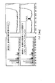
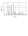
- the powder X-ray diffraction result of the positive electrode material obtained in Example 1 is shown in FIG.
- the positive electrode material sample of Example 1 is a pyrolytic carbon layer deposited LiFePO 4 containing a ferromagnetic Fe component (metallic iron), a trivalent Fe compound, a Li 3 PO 4 crystal, and an Fe 2 P crystal as impurities.
- Comparative Example 1 On the other hand, for the above Example 1, the raw materials and intermediates were handled as much as possible while avoiding the mixing of moisture and oxygen, and the same conditions as described above were used except that the sample was not exposed to the atmosphere after secondary firing. Thus, the positive electrode material of Comparative Example 1 was manufactured.
- the positive electrode material had a specific surface area of 20.0 m 2 / g, an average diameter of about 90 nm as observed with an electron microscope, and a carbon deposition amount of 5.6% by mass.
- both the ferromagnetic and antiferromagnetic components were below the lower detection limit (less than 0.001 emu / g) by magnetization measurement with a SQUID magnetometer performed at 25 ° C. and 60 K. It was confirmed that it was less than about 5 ppm by mass in the positive electrode material in terms of metallic iron. Also, in Mossbauer spectroscopy measurement performed on this sample at 25 ° C. and about 85 K, the isotope peak shift (IS) value corresponding to the trivalent Fe compound or Fe 2 P is in the range of ⁇ 0.5 to 1 mm / s. Had no peaks and shoulders, and no peaks corresponding to other by-product Fe compounds were observed.
- IS isotope peak shift
- the powder X-ray diffraction result of the positive electrode material obtained in Comparative Example 1 is shown in FIG.
- the positive electrode material sample of Comparative Example 1 is considered to be a LiFePO 4 positive electrode material that has almost no impurities, no Li ion conductive material layer, and only a pyrolytic carbon layer. It is done.
- NMP N-methylpyrrolidone
- acetylene black as a conductive auxiliary agent
- PVDF polyvinylidene fluoride
- a coating solution added, mixed and dispersed at a ratio of the property assistant: binder 91: 4: 5 was prepared, coated on an aluminum foil, dried and pressed, and loaded with a positive electrode material of about 8 mg / cm 2 .
- a coin battery was created.
- the positive electrode material of Example 1 includes ferromagnetic components such as iron oxide and metallic iron. It is recognized that up to about 1% by mass (10000 ppm by mass) does not show a significant adverse effect on the above-described high-temperature charge / discharge cycle characteristics.
- Li 4 P 2 O 7 is formed as a Li ion conductive material layer and vapor deposition is further performed thereon by adopting a raw material charging composition in which the raw materials of Li and P are excessive with respect to the theoretical composition of the active material olivine type LiFePO 4.
- Reagents Li 2 CO 3 , NH 4 H 2 PO 4 , and FeC 2 O 4 .2H 2 O are in excess of the theoretical composition ratio of LiFePO 4 at a predetermined ratio of Li and P with respect to the stoichiometric ratio.
- the temperature was increased in a rotary furnace having a quartz glass sample heating tube while nitrogen gas was circulated at 500 ml / min, and maintained at 500 ° C. for 5 hours.
- the temperature is raised to 700 ° C., and butane gas as a carbon layer precursor is added to the surface of the sample heating tube at 100 ml / min for 5 minutes to thereby deposit on the surface of the active material particles on which the Li ion conductive layer being fired is deposited.
- a conductive carbon layer was deposited by deposition.
- the diffraction peak intensity of this Li 4 P 2 O 7 crystal is quite weak as 10% in terms of the distribution ratio of Li element in the positive electrode material. Therefore, the total amount of Li and P excess charged raw materials is Li 4. It is presumed that the P 2 O 7 crystal has not changed, and an amorphous compound having a composition close to this crystal coexists.
- Reference Example 1 In the same synthesis procedure as described above, a positive electrode material in which no Li ion conductive material layer was formed from excess Li and P raw materials was synthesized as “Reference Example 1” by adopting a stoichiometric composition.
- NMP N-methylpyrrolidone
- acetylene black as a conductive auxiliary agent
- PVDF polyvinylidene fluoride
- positive electrode material conductive auxiliary agent: amount of binder
- a positive electrode mixture was prepared.
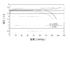
- the LiFePO 4 positive electrode material of Example 2 in which Li 4 P 2 O 7 was deposited as a Li ion conductive layer and conductive pyrolytic carbon was further deposited thereon was the only pyrolytic carbon. It can be seen that the polarization is reduced as compared with the deposited LiFePO 4 positive electrode material of Reference Example 1 and shows a better discharge rate characteristic. This is because the Li 4 P 2 O 7 as the Li ion conductive material layer deposited on the lower layer of the conductive carbon layer causes defects through which Li ions in the conductive carbon layer can pass, and the one-dimensional Li ion conductive olivine. This is considered to be a result of enhancement and expansion of the Li ion conduction route connecting between the b-axis direction crystal end faces (see FIG. 3) of the type LiFePO 4 active material crystal.
- Example 2 the content of the ferromagnetic component is 0.01 emu / g or less (approximately 50 mass ppm or less in terms of metallic iron) in the magnetization measurement using the sample vibration magnetometer at room temperature. Met.
- the content of the ferromagnetic component is low, considering the result of Example 1 above, the gap between the through hole in the conductive carbon layer and the end surface of the electrode active material is substantially reduced. It is considered that a Li ion conduction path is formed by the Li ion conductive material layer that connects the two.
- Example 2 obtained by adding an excessive amount of Li source and phosphoric acid source material, the Li ion conductive material layer was further enhanced, so that a discharge rate characteristic higher than that of Reference Example 1 was obtained. It is estimated to be.
- Example 3 Reagents LiOH ⁇ H 2 0, MnSO 4 ⁇ H 2 0 in the raw material aqueous solution close to saturation at room temperature to create respectively, to 40% dimethyl sulfoxide aqueous solution of 85% phosphoric acid (H 3 PO 4), Li : Mn: P
- the mixture was sequentially mixed with stirring so that the molar ratio was 3: 1: 1.
- the mixed solution was heated and reacted at about 105 ° C., and after cooling, the precipitate of the reaction product was collected with a centrifuge.
- the reaction product was washed with distilled water and then vacuum dried at 80 ° C. to obtain a LiMnPO 4 positive electrode active material substrate.
- a positive electrode material sample coated on this LiMnPO 4 substrate with a layer (coexistence layer) in which an amorphous ion conductive material of assumed composition Li 2 FeP 2 O 7 and conductive carbon by pitch pyrolysis are present together is as follows: Created in the way. First, reagents LiOC 2 H 5 , FeC 2 O 4 .2H 2 O, and [CH 3 (CH 2 ) 3 O] 3 P ⁇ O are mixed at a charging ratio of 2: 1: 2 in a molar ratio of Li: Fe: P. did. Then, 2.74 g of the mixture was added to and mixed with 20 g of the LiMnPO 4 substrate. 1.20 g of 250 ° C.
- the specific surface area measured by the nitrogen adsorption BET multipoint method for the positive electrode material of Example 3 was 40 m 2 / g (area equivalent diameter was about 44 nm).
- the powder X-ray-diffraction result of this positive electrode material is shown in FIG. In this figure, there is no diffraction peak of crystals other than the active material LiMnPO 4 , and the Fe-containing lithium pyrophosphate exists in an amorphous state in the coexisting layer deposited on the LiMnPO 4 substrate. It can be judged.
- the positive electrode material contained a compound having a composition corresponding to Li 2 FeP 2 O 7 .
- the specific surface area measured by the nitrogen adsorption BET multipoint method for the positive electrode material of Reference Example 2 was about 41 m 2 / g (area equivalent diameter was about 43 nm). Further, the X-ray diffraction result of Reference Example 2 was almost the same as that of Example 3, and there was no significant difference in the position, intensity, relative intensity ratio, and half-value width of the crystal peak corresponding to LiMnPO 4 . Since the X-ray diffraction results and specific surface area values of Example 3 and Reference Example 2 are almost equal, in both cases, the active material LiMnPO 4 crystals have substantially the same primary particle size ( ⁇ crystallite size). It was determined that
- NMP N-methylpyrrolidone
- acetylene black as a conductive additive
- PVDF polyvinylidene fluoride
- an electrolyte solution of ethylene carbonate: ethyl methyl carbonate 3: 7 in which 1 M LiPF 6 was dissolved by incorporating it into a metal Li foil negative electrode through a porous polyolefin separator.
- a 2032 type coin battery was added.
- the coin batteries of Example 3 and Reference Example 2 were charged at a constant current of up to 4.5 V at 0.01 C, and then charged at a constant voltage of 4.5 V (end current 0.001 C). Thereafter, a constant current was discharged to 2.5 V at 0.01 C, and charge / discharge characteristics were measured. The charge / discharge characteristics were also measured by changing the constant current charge condition to 0.1 C, the constant voltage charge end current to 0.01 C, and the constant current discharge condition to 0.1 C. The results of these discharge tests are shown in FIGS. 12 and 13, respectively. In these figures, the capacity based on the total amount of the amorphous Fe-containing lithium pyrophosphate and the active material LiMnPO 4 is shown.
- LiMnPO 4 positive electrode material in which a coexisting layer of amorphous Fe-containing lithium pyrophosphate and pitch pyrolytic carbon was deposited was 157 mAh / g at the time of 0.01 C discharge and 146 mAh at the time of 0.1 C discharge.
- a discharge capacity of / g was shown.
- the discharge capacity when correcting the content of the amorphous Fe-containing lithium pyrophosphate and based on the amount of the active material LiMnPO 4 is 164 mAh / g, which approaches the theoretical capacity of 171 mAh / g at the time of 0.01 C discharge, And it was 151 mAh / g at the time of 0.1-C discharge.
- the crystal end face of the one-dimensional ion conductive LiMnPO 4 active material, the ion conductive material layer made of amorphous Fe-containing lithium pyrophosphate, and the coexisting layer of conductive carbon generated by thermal decomposition were deposited. It can be seen that the LiMnPO 4 positive electrode material exhibits good characteristics. This is considered to be a result of the ion conductive material layer (amorphous Fe-containing lithium pyrophosphate salt) becoming a conduction path for Li ions, and it can be seen that good discharge characteristics are exhibited at a low discharge rate.
- the ion conductive material layer (amorphous Fe-containing lithium pyrophosphate) raw material and the pitch of the carbon precursor were mixed and baked to form ions on the LiMnPO 4 substrate.
- the conductive material layer and the conductive carbon layer are deposited simultaneously.
- a part of the ion conductive material layer covers at least a part of the crystal end face where Li ions of the LiMnPO 4 positive electrode material base can diffuse, and the remaining ion conductive material. At least a part of the layer is in a state of penetrating in the thickness direction of the conductive carbon layer.
- both of the ion conductive material layers exist on the surface of the electrode active material in a state where a part of the ion conductive material layer penetrates into the through hole in the thickness direction in the conductive carbon layer, and these ion conductive material layers as a whole are Li. It can be said that an ion conduction path is formed.
- the ratio of the amount of Li ions in the formed Li ion conductive material layer and the positive electrode active material is within the range of the above formula (1). It was. Further, it was found by observation with a transmission electron microscope and a scanning electron microscope that primary particles are bound together by conductive carbon and a Li ion conductive substance to form secondary particles. Moreover, on the surface of the primary particle of each Example, the coexistence layer of electroconductive carbon and Li ion conductive substance exists in the whole surface, and the thickness as a whole of these is about 1 in all. It was in the range of ⁇ 3 nm.
- Electrode material for secondary battery 1 electrode material for secondary battery, 2 electrode active material, 3 ion conductive material layer, 4 conductive carbon layer, 5 cation, 6 allowable movement direction of cation, 7 end face, 8 passage hole, 10 Secondary particles of secondary battery electrode material, 11 Primary particles of secondary battery electrode material, 12 electrode active material, 13 ion conductive material layer, 13a part of an ion conductive material layer, 14 conductive carbon layer, 18 passage hole,
Landscapes
- Chemical & Material Sciences (AREA)
- Chemical Kinetics & Catalysis (AREA)
- Electrochemistry (AREA)
- General Chemical & Material Sciences (AREA)
- Inorganic Chemistry (AREA)
- Engineering & Computer Science (AREA)
- Organic Chemistry (AREA)
- Materials Engineering (AREA)
- Manufacturing & Machinery (AREA)
- Composite Materials (AREA)
- Crystallography & Structural Chemistry (AREA)
- Battery Electrode And Active Subsutance (AREA)
Abstract
Description
尚、前記リチウムイオンの拡散性の低さは、オリビン型結晶構造(斜方晶系、空間群Pnma)の電極活物質の結晶構造にも由来する。オリビン型電極活物質は、図3に示すような空間群Pnma型の結晶格子構造をとり、その結晶格子内部においてLi、Na、及びMg等のカチオンが結晶b軸方向のリチウムイオンサイトをつなぐ一次元トンネル内の許容移動方向のみを移動し得る構造となっている。そのため、前記カチオンの移動方向が一方向のみに限られるため、イオン拡散の自由度が低いことが知られている。
特許文献2では、前記リチウムイオン伝導性物質層によりリチウムイオンの拡散の自由度が向上し、出力特性が改善されることが記載されているが、活物質粒子の導電性炭素被覆については言及されていない。
特許文献4には、活物質の表面に部分的にリチウムイオン伝導性ポリマーが被覆され、前記リチウムイオン伝導性ポリマーが被覆されていない部分には、導電剤あるいは導電剤とリチウムイオン伝導性無機固体電解質により部分的あるいは全面的に被覆されている電極材料が開示されている。
また、特許文献5には、活物質の表面に、導電剤とリチウムイオン伝導性無機固体電解質を含む被覆層を備えた電極材料が開示されている。
ここで、イオン伝導性物質と導電性炭素の共存層は、前記一次粒子の表面を全部覆っていなくてもよい。少なくとも全表面の5割以上を覆っていればよい。5割以上の場合、一次粒子の表面に偏りなく散在することが好ましい。
ここで、前記イオン伝導性物質と導電性炭素の共存層の厚さは、総体として約1~30nm程度、好ましくは約1~10nm程度である。
ここで、「一次粒子の表面の少なくとも一部に存在するイオン伝導性物質層」における「少なくとも一部」の割合としては、全表面の5割以上であることが好ましい。5割以上の場合、一次粒子の表面に偏りなく散在することが好ましい。
本態様によれば、前記第1の態様とほぼ同様の作用効果が得られる。
また、「少なくとも前記イオン伝導性物質層の表面の少なくとも一部に存在する導電性炭素層」において、「少なくとも前記イオン伝導性物質層」とは、イオン伝導性物質層の表面だけに導電性炭素が存在する構成の他に、イオン伝導性物質層が存在しない電極活物質の表面にも更に導電性炭素層が存在する構成を含む意味である。
ここで、前記電極活物質2は、電気化学的酸化または還元に伴って1価または2価金属のカチオンを放出または吸蔵し、前記酸化または還元の過程で、結晶格子内部で一次元の許容移動方向(符号6)のみを前記カチオンが移動し得る結晶構造を有している。すなわち、前記カチオンは、電極活物質における前記カチオンの許容移動方向と交差する2つの端面(符号7)側からのみ放出または吸蔵される。
前記イオン伝導性物質層は、前記カチオンの許容移動方向と交差する前記一次粒子の端面を被覆しているので、該端面から放出されるカチオンはイオン伝導性物質層に取り込まれ、該イオン伝導性物質層においては二次元または三次元的な内部移動が可能となる。結果として、前記カチオンはイオン伝導性物質層の表面のどこからでも放出されることになる。
即ち、電極活物質2の一次粒子の表面の少なくとも一部に存在するイオン伝導性物質層3と、炭素前駆体を熱分解することにより形成され、少なくとも前記イオン伝導性物質層3の表面の少なくとも一部に存在する導電性炭素層4とを備え、前記イオン伝導経路が形成される構造であればよい。
また、一般式AMDO4のDは、P(リン)と後述するYで構成されていてもよい。YはAl、Si、S、VおよびMoの内のいずれか1種または複数の組合せであり、xおよびyは0以上0.4以下で、且つどちらか一方は0でない数であり、またaは1以下の正の数で、かつ該化合物が電気的中性を保持するように選ばれるものである。
また、これらの前記AとD、またはA、D及びMも含む該イオン伝導性物質層は、少なくとも部分的に非晶質状態にあることが好ましい。
例えば、前記電極活物質AMDO4がオリビン型構造を有するLiFePO4である場合、前記イオン伝導層物質層の好ましい一例は、前記AMDO4におけるAとDを含む(ポリ)リン酸塩として、Li4P2O7またはLi3PO4、乃至はそれらの中間的組成の化合物を含んでいる。
また、好ましい態様では、前記イオン伝導性物質層に含まれ、前記カチオン(ここではLi)のイオン伝導性機能を維持しながら、導電性(電子伝導性)も付与する、前記Mとしての2価および/または3価のFeが、上記Li4P2O7またはLi3PO4、乃至はそれらの中間的組成の化合物中のLiの一部と置換した状態で含まれる。具体例を挙げると、前記イオン伝導層物質層は、例えば、以下の組成の化合物の内の少なくともいずれか一種を含む:
Li3-2xFe(II)xPO4、Li2-2xFe(II)xP2O7、Li3-3xFe(III)xPO4、Li2-3xFe(III)xP2O7、Li9-4xFe(II)2x(PO4)3、Li9-6xFe(III)2x(PO4)3
上記において、xは1以下、好ましくはおよそ0.3以下の正の数であり、Liの係数は正の数である。また、該イオン伝導性物質層は、少なくとも部分的に非晶質状態にあることが好ましい。
(A)1価または2価金属のカチオンを含有した酸化物、硫化物、リン酸塩、ケイ酸塩、およびそれらの窒化物の群から選ばれる一種、または
(B)前記(A)群から選ばれる複数の物質の複合体
であることを特徴とするものである。

また、「共存水分量を規定する」とは、前記混合原料中に含まれる水分量が所定の濃度範囲になるよう該混合原料に水分を気相中から又は液相中から添加することである。この水分量は混合原料に対し0.1~25質量%の範囲になることが好ましい。
また、「混合原料の到達粒径を規定する」とは、乾式又は湿式での粉砕により混合原料の粒度を調整することであり、その平均粒径が0.5~10μmの範囲になることが好ましい。
このとき、後述するMの酸化物(または金属状態のM)やM(III)化学種が上述の一連の工程で生じ、これらが生成した分、全原料中のA及びD由来のリン酸イオンがMに比べ化学量論的に過剰になる。そして、この過剰になったA及びリン酸イオンから、前記イオン伝導性物質層が形成される。
このとき、A源となる原料、M源となる原料、D源となる原料の混合原料から、電極活物質とイオン伝導性物質層を同時に合成し、表面にイオン伝導性物質層を備えた電極活物質を得ることができる。このことによって、化学量論比、乃至はその近傍の仕込み組成のリチウム(Li)源、リン酸源、Fe源化合物の混合原料からも、目的の前記イオン伝導性物質層を備えた電極活物質が合成され、当該電極材料を製造することが可能となる。さらに、当該電極材料は、前述の第6の態様、第7の態様及び第10の態様も兼ね備える。
本態様によれば、第13の態様とほぼ同様の作用効果が得られる。
なお、第14の態様と第15の態様を比較すると、後者の方が高特性の電極材料が得られる場合が多い。
なお、第13の態様乃至第16の態様においては、カチオンAの量が、想定されるイオン伝導性物質層の組成において、第8の態様の式(1)を満たすように、各材料の仕込み組成が調整される。
本発明に係る二次電池用電極材料における電極活物質としては、その結晶一次粒子が、電気化学的酸化または還元に伴って1価または2価金属のカチオンを放出または吸蔵し、前記酸化/還元の過程で、結晶格子内部で一次元の許容移動方向のみを前記カチオンが移動し得る結晶構造を有するものが用いられる。ここで、前記カチオンとしては、例えばLi、Na、及びMgが用いられる。
また、前記一般式Lia(Fe1-x-zMnz )M”xPO4で表される化合物の一次粒子においては、Liイオンの許容移動方向の平均径が、約20nm以上かつ約300nm以下であることが好ましい。特に、z/(1-x)の値が0.8以上である場合は、該平均径が約20nm以上、且つ約70nm以下であることが好ましい。
イオン伝導性物質層に用いられるイオン伝導性物質は、二次元または三次元的な前記カチオンの内部移動を許容する性質を有する。より好ましくはそれに加えて電子伝導性を有する。さらに好ましくは、前記イオン伝導性物質層は、前記カチオンの拡散移動に基づく10-8S/cm相当以上のイオン伝導性と、電子伝導に基づく10-8S/cm以上の導電性(電子伝導性)を有する。さらに一層好ましくは、10-6S/cm相当以上の前記イオン伝導性と、10-6S/cm相当以上の導電性(電子伝導性)を有する。
[酸化物、ケイ酸塩、リン酸塩系]
Li2TiO3、Li4Ti5O12、Li2ZrO3、LiVO3、
LiNbO3、Li2CrO4、Li2MoO4、Li2WO4、
LiAlO2、Li4Al2O5、LiGaO2、LiInO2、
Li2SiO3、Li2Si2O5、Li2GeO3、
Li2SnO3、Li3PO4、Li4P2O7、Li14Zn(GeO4)4、
Li3V2(PO4) 3、LaLiTi2O6、Li‐β‐アルミナ等
[硫化物、窒化物系]
Li4-xSi1-xPxS4、 Li4-xGe1-xPxS4、
Li4-xGe1-xGaxS4、 Li3+5xP1-xS4、
Li3+xPO4-xNx、 (Li2S)x(SiS2)1-x、
(Li2S)x(SiS2)y(Li3PO4)1-x-y等
Li3-2xFe(II)xPO4、 Li2-2xFe(II)xP2O7、
Li3-3xFe(III)xPO4、 Li2-3xFe(III)xP2O7、
Li9-4xFe(II)2x(PO4)3、 Li9-6xFe(III)2x(PO4)3等
Li3-3xMn(III)xPO4、 Li2-3xMn(III)xP2O7、
Li9-4xMn(II)2x(PO4)3、
Li9-6xMn(III)2x(PO4)3、Li9-4xV(II)2x(PO4)3、
Li9-6xV(III)2x(PO4)3等
以上から、これらの過程で余剰になったLi及びリン酸イオンから、目的のイオン伝導性物質層として、少なくとも部分的に非晶質構造を有するLi4P2O7またはLi3PO4、乃至はそれらの中間的組成の化合物を層状析出させることができる。
また、前記Fe(III)化学種は、電極活物質の原料粉砕・混合過程、及び粉砕後原料、反応中間体や最終生成物の焼成工程、及び大気中での取り扱い過程における、原料Fe(II)源、反応中間体Fe(II)種、及び最終生成物LiFePO4の空気酸化によって生じる。前記Fe(III)化学種(通例、常温では常磁性を示す)は、焼成工程中に後述の導電性炭素層による還元を受け、約700~720℃以上では、その一部がリン化物(主にFe2P:キュリー温度約210Kの強磁性体で、室温では常磁性)に変性して、最終生成物中に残留する。

導電性炭素層は、熱分解によって導電性炭素を生じ得る炭素前駆体を用い、該炭素前駆体と電極活物質、またはその原料ないしその反応中間体とを混合し、主として不活性ガスからなる雰囲気下において焼成することにより設けることができる。
こうした問題を回避するためには、炭化触媒能を持つ物質を電極活物質の表面近傍に共存させる必要があるが、通例、それは容易ではない。この時、前記電極活物質の表面を被覆する前記イオン伝導性物質層が該触媒能を有していれば、こうした問題は非常に効果的に解消される。
例えば、高極性溶媒(例えば水、融解エチレンカーボネート、プロピレンカーボネート、N-メチルピロリドン、ジメチルスルフォキシド等)に対する前記電極活物質表面の濡れ性は、前記通過孔の貫通(開孔)が大きく、数が多いほど高まるため、該濡れ性評価に用いられる一般的評価手段(例えば前記電極材料の充填層へのこれら高極性溶媒の染み上がり速度の評価)により、前記通過孔の貫通(開孔)の程度を相対的に評価することができる。また、例えば、前記電極活物質の表面のゼータ電位測定等によっても、表面の極性評価が可能であり、前記通過孔の貫通(開孔)の程度を相対的に評価できる。
次に、本発明に係る二次電池用電極材料の一次粒子について図に基いて説明する。図1は、本発明に係る二次電池用電極材料の一次粒子の構成を示す概略図である。図2は、本発明に係る二次電池用電極材料の二次粒子の構成の一例を示す概略図である。
そして、前記カチオン5は該通過孔8を通って放出され、前記電極材料1に接する外部の電解質9(電解液、固体電解質等)との間でイオン伝導経路ができる。電極活物質2によるカチオン5の吸蔵は、前記放出過程の逆の移動経路を辿ればよい。
本発明者等は、前記貫入構造の有無により充放電特性に差があり、これがある方が充放電特性が向上する場合が多い(後述)。
試薬LiOH・H2O、FeC2O4・2H2O及びNH4H2PO4を、Feに対してLiおよびPが化学量論比、すなわちLi:Fe:Pのモル比1:1:1の仕込み比率で十分に粉砕及び混合した後、混合物(粉末)をN2ガス気流下で400℃にて10時間一次焼成した。この一次焼成中間体100質量部に対し、JFEケミカル製250℃軟化ピッチMCP-250Dを約7質量部加えて十分に粉砕及び混合し、その混合物をN2ガス気流下で780℃にて10時間二次焼成した。
この実施例1においては、粉砕及び混合した後の原料、及び一次焼成後の反応中間体を、大気(約20℃、相対湿度約60%)に約1日ずつ暴露させた。これにより、混合原料中に約1質量%の水分を大気中から吸収した。また一次焼成後に大気暴露した反応中間体中には、含有量にして約20000質量ppm相当の酸化鉄γ-Fe2O3が含まれていることが、メスバウア分光及び飽和磁化測定より判明した。これらの酸化鉄は、前述の大気暴露で生じたと見なすことができる。
前記二次焼成物を、粗粉砕して解砕し、Liイオン伝導層、および更にその上層にピッチ熱分解による導電性炭素層を積層析出させたLiFePO4正極材料を得た。この正極材料の比表面積は約20.5m2/g、電子顕微鏡観察による平均径は約70nmであり、また炭素析出量は5.6質量%であった。これを実施例1とする。
このため、本実施例1の正極材料においても、前記強磁性成分は金属鉄であると考えられる。この金属鉄は、前記二次焼成前の反応中間体中に存在した酸化鉄が、二次焼成中に、共に生じる炭素またはその前駆体のピッチにより還元され生じたものである。
なお、二次焼成温度が約700℃未満の場合、前記金属鉄は金属状態までは還元されず、FeOやその関連物質の形で正極材料中に残存することが多い。
この正極材料を1~2ヶ月大気暴露しても、含まれる前記金属鉄は空気酸化されなかった。従って、共存する金属鉄や、これと同時に形成されたLiイオン伝導層は、ピッチの熱分解で生じた導電性炭素層の下層に存在すると考えられる。
その結果、活物質LiFePO4にLiイオン伝導層物質層、更にその上に導電性炭素層が形成された正極材料となっていると言うことができる。
一方、上記実施例1に対し、原料および中間体の取扱いを水分及び酸素の混入を極力避けて行い、二次焼成後に試料を取り出すまで大気に触れさせなかった以外は、上記と同一の条件にて、比較例1の正極材料を製造した。この正極材料の比表面積は20.0m2/g、電子顕微鏡観察による平均径は約90nmであり、また炭素析出量は5.6質量%であった。
また、この試料に対して25℃および約85Kで実施したメスバウア分光測定においても、3価Fe化合物やFe2Pに相当する同位体ピークシフト(IS)値-0.5~1mm/sの範囲には、ピークおよびショルダーは全くなく、またそれ以外の副生成Fe化合物に相当するピークも全く認められなかった。
以上のことから、比較例1の正極材試料は、不純物が殆どなく、Liイオン伝導性物質層が形成されていない、熱分解炭素層のみが形成されたLiFePO4正極材料となっていると考えられる。
図6より、化学量論比組成から固相焼成で得られた導電性炭素層析出LiFePO4正極材の内、制御した一定の条件において粉砕後原料及び反応中間体を大気暴露して副生成物を生じさせ、その結果Liイオン伝導性物質層が形成されたと考えられる実施例1の正極材料は、良好な放電レート特性を示すことが判る。
一般に、LiFePO4正極材料中に混在する金属鉄や酸化鉄等の強磁性成分は、常温より高い温度での充放電中に溶出して負極側に移行し、金属鉄として負極上に再析出して電解液を電気分解するため、サイクル特性を劣化させると言われている。
発明者らの評価では、実施例1と同様の構成を持つ、化学量論比の原料から焼成によって得た導電性炭素析出LiFePO4正極材料においては、鉄酸化物・金属鉄等の強磁性成分として、約1質量%(10000質量ppm)までは上述した高温充放電サイクル特性への顕著な悪影響が見られないことが認められている。
LiおよびPの原料が活物質オリビン型LiFePO4の理論組成に対して過剰となる原料仕込み組成の採用により、Liイオン伝導性物質層としてLi4P2O7を、更にその上層に気相析出熱分解炭素層を積層析出させたLiFePO4正極材料(活物質:イオン伝導層の組成比=0.9LiFePO4:0.025Li4P2O7)を、以下の要領で合成した。
このLi4P2O7結晶の回折ピーク強度は、上記正極材料中にLi元素の分配率で1割存在するものとしてはかなり弱いことから、LiおよびPの過剰仕込原料分は全量がLi4P2O7結晶には変化してはおらず、これに近い組成の非晶質化合物も共存して析出していることが推察される。
以上と同一の合成手順にて、化学量論比仕込み組成の採用により、余剰分のLi及びP原料からのLiイオン伝導性物質層の形成がない正極材料を「参考例1」として合成した。この正極材料の炭素含有量は前記実施例2とほぼ同等の1.7質量%であり、図8に示すように、また粉末X線回折結果では、2θ=約28度にはLi4P2O7結晶の回折ピークは認められなかった。
試薬LiOH・H20、MnSO4・H20の室温において飽和に近い原料水溶液をそれぞれ作成し、85%リン酸(H3PO4)の40%ジメチルスルホキシド水溶液に対し、Li:Mn:Pのモル比が3:1:1となるよう攪拌しながら順次混合した。この混合液を約105℃で加熱反応させ、冷却後、遠心分離機で反応生成物の沈殿を回収した。反応生成物を蒸留水で洗浄後、80℃にて真空乾燥し、LiMnPO4の正極活物質基体を得た。
先ず、試薬LiOC2H5、FeC2O4・2H2O、[CH3(CH2)3O]3P=OをLi:Fe:Pのモル比2:1:2の仕込み比率で混合した。そして前記LiMnPO4基体20gに対して、該混合物を2.74g添加、混合した。JFEケミカル株式会社製の250℃軟化ピッチMCP-250Dを、前記LiMnPO4基体と上記3試薬との混合物22.74gに対して1.20g加えて混合し、焼成前駆体混合物を得た。
得られた焼成前駆体混合物をN2気流下で710℃にて焼成し、想定組成Li2FeP2O7のFe含有ピロリン酸リチウム塩からなるイオン伝導性物質と、ピッチ熱分解による導電性炭素との共存層(複合層)を析出させたLiMnPO4正極材料を得た。これを実施例3とする。
また、この正極材料の粉末X線回折結果を図11に示す。この図において、活物質LiMnPO4の他に結晶の回折ピークは認められず、LiMnPO4基体に析出させた前記共存層中において、前記Fe含有ピロリン酸リチウム塩は非晶質状態で存在していると判断することができる。
また、ICP発光分光法によるLi、Fe、Pの元素分析及び炭素量測定により、この正極材中には、Li2FeP2O7に相当する組成の化合物が含有されていると判断した。この正極材料中の質量組成比は、およそLiMnPO4:Li2FeP2O7:C=91.7:3.9:4.4であった。
一方、上記の実施例3に対し、想定組成Li2FeP2O7のFe含有ピロリン酸リチウム塩を析出させず、熱分解炭素層のみを析出させたLiMnPO4正極材を以下の要領で作成した。
実施例3と同一の前記LiMnPO4基体20gに対し、JFEケミカル株式会社製の250℃軟化ピッチMCP-250Dのみを1.15g添加した以外は、上記実施例3と同一の条件にて、熱分解炭素層のみを析出させたLiMnPO4正極材を製造した。これを参考例2とする。
この正極材料中の質量組成比は、LiMnPO4:C=95.6:4.4であった。
実施例3と参考例2のX線回折結果および比表面積値がほとんど等しいことから、両者においては、活物質LiMnPO4結晶が、互いにほぼ等しい1次粒径(≒結晶子サイズ)を有していると判断された。
また、定電流充電条件を0.1C、定電圧充電終止電流を0.01C、および定電流放電条件を0.1Cに変更した充放電特性も測定した。
これらの放電試験の結果をそれぞれ図12および図13に示す。これらの図では、非晶質Fe含有ピロリン酸リチウム塩と活物質LiMnPO4の合計量を基準とした容量を示した。
尚、非晶質Fe含有ピロリン酸リチウム塩の含有量を補正し、活物質LiMnPO4量を基準とした場合の放電容量は、0.01C放電時では理論容量171mAh/gに迫る164mAh/g、及び0.1C放電時で151mAh/gであった。
従って、実施例3の非晶質Fe含有ピロリン酸リチウム塩とピッチ熱分解炭素の共存層を析出させたLiMnPO4正極材料は、非晶質Fe含有ピロリン酸リチウム塩の含有量を補正しない場合でも、参考例2の炭素層析出のみのLiMnPO4正極材料よりも大きな放電容量を示すことがわかる。
これは、イオン伝導性物質層(非晶質Fe含有ピロリン酸リチウム塩)がLiイオンの伝導経路となった結果と考えられ、低い放電レートにおいて、良好な放電特性を示すことがわかる。
また、それぞれの実施例の一次粒子の表面においては、いずれもほぼその全面に導電性炭素及びLiイオン伝導性物質の共存層が存在しており、それらの総体としての厚みは、いずれも約1~3nmの範囲内であった。
4 導電性炭素層、 5 カチオン、 6 カチオンの許容移動方向、
7 端面、 8 通過孔、
10 二次電池用電極材料の二次粒子、 11 二次電池用電極材料の一次粒子、
12 電極活物質、 13 イオン伝導性物質層、
13a イオン伝導性物質層の一部、 14 導電性炭素層、 18 通過孔、
Claims (16)
- 電気化学的酸化または還元に伴って1価または2価金属のカチオンを放出または吸蔵し、前記酸化または還元の過程で、結晶格子内部で一次元の許容移動方向のみを前記カチオンが移動し得る電極活物質の結晶一次粒子と、
前記一次粒子の表面に共存するイオン伝導性物質と炭素前駆体を熱分解することにより生じた導電性炭素と、を備え、
前記イオン伝導性物質は、二次元または三次元的な前記カチオンの移動を許容する性質を有するものであり、
前記カチオンは、前記共存するイオン伝導性物質と導電性炭素の共存層を介して移動可能であることを特徴とする、二次電池用電極材料。 - 電気化学的酸化または還元に伴って1価または2価金属のカチオンを放出または吸蔵し、前記酸化または還元の過程で、結晶格子内部で一次元の許容移動方向のみを前記カチオンが移動し得る電極活物質の結晶一次粒子と、
前記一次粒子の表面の少なくとも一部に存在するイオン伝導性物質層と、
炭素前駆体を熱分解することにより形成され、少なくとも前記イオン伝導性物質層の表面の少なくとも一部に存在する導電性炭素層と、を備え、
前記イオン伝導性物質層は、二次元または三次元的な前記カチオンの移動を許容する性質を有し、
前記カチオンは、前記イオン伝導性物質層と導電性炭素層を介して移動可能に構成されていることを特徴とする、二次電池用電極材料。 - 電気化学的酸化または還元に伴って1価または2価金属のカチオンを放出または吸蔵し、前記酸化または還元の過程で、結晶格子内部で一次元の許容移動方向のみを前記カチオンが移動し得る電極活物質の結晶一次粒子と、
前記一次粒子の表面の少なくとも一部に存在するイオン伝導性物質層と、
炭素前駆体を熱分解することにより形成され、少なくとも前記イオン伝導性物質層の表面の少なくとも一部に存在する導電性炭素層と、を備え、
前記イオン伝導性物質層は、二次元または三次元的な前記カチオンの移動を許容する性質を有し、
前記導電性炭素層は、該導電性炭素層の厚み方向に前記カチオンを通過し得る通過孔を有し、
前記カチオンの許容移動方向と交差する前記一次粒子の端面と前記導電性炭素層の通過孔とが、前記イオン伝導性物質層を介して繋がるように構成されていることを特徴とする、二次電池用電極材料。 - 請求項1~3のいずれか一項に記載の二次電池用電極材料において、
前記電極活物質は、一般式AMDO4で表される物質であり、
ただし、前記一般式AMDO4において、
Aは、カチオンであって、かつLi、NaおよびMgの内のいずれか1種または複数の組合せであり、
Mは、Fe、Mn、CoおよびNiの内のいずれか1種または複数の組合せ、または、
Fe、Mn、CoおよびNiの内のいずれか1種または複数の組合せとMg、Ca、Sc、Ti、Zr、V、Nb、Cr、Mo、W、Cu、Zn、Al、Ga、InおよびSnの内のいずれか1種または複数の組合せの両方を含むものであり、
Dは、P、または、
Pと、Al、Si、S、VおよびMoの内のいずれか1種または複数の組合せであり、
前記AMDO4全体として電気的中性が保持されていることを特徴とする、二次電池用電極材料。 - 請求項4に記載の二次電池用電極材料において、
前記イオン伝導性物質層は、前記AMDO4におけるAとDを含むオキソ酸塩の層を備え、前記カチオンのイオン伝導性機能を少なくとも有することを特徴とする、二次電池用電極材料。 - 請求項1~5のいずれか一項に記載の二次電池用電極材料において、
前記イオン伝導性物質層を形成するイオン伝導性物質は、
(A)1価または2価金属のカチオンを含有した酸化物、硫化物、リン酸塩、ケイ酸塩、およびそれらの窒化物の群から選ばれる一種、または
(B)前記(A)群から選ばれる複数の物質の複合体
であることを特徴とする、二次電池用電極材料。 - 請求項1~6いずれか一項に記載の二次電池用電極材料において、
前記イオン伝導性物質層は、少なくとも一部に非晶質構造を有することを特徴とする、二次電池用電極材料。 - 請求項1~7のいずれか一項に記載の二次電池用電極材料において、
前記電極活物質中の前記カチオンのモル分配率と、前記イオン伝導性物質中の前記カチオンのモル分配率との比の値は、以下の式(1)の範囲で表されることを特徴とする、二次電池用電極材料。

- 請求項1~8いずれか一項に記載の二次電池用電極材料において、
前記イオン伝導性物質層の少なくとも一部が、前記導電性炭素層の前記通過孔の内側に貫入していることを特徴とする、二次電池用電極材料。 - 請求項1~9いずれか一項に記載の二次電池用電極材料において、
複数の前記一次粒子同士が、前記イオン伝導性物質および/または前記導電性炭素層の少なくとも一部を介して結着し、二次粒子を構成していることを特徴とする、二次電池用電極材料。 - 請求項1~10のいずれか一項に記載の二次電池用電極材料を、正極または負極の構成部材として含むことを特徴とする、二次電池。
- 一般式AMDO4で表される電極活物質を、A源となる原料、M源となる原料、D源となる原料を混ぜた焼成前駆体を一次焼成し、その後に熱分解することにより導電性炭素を生じる炭素前駆体を加えて二次焼成し、導電性炭素層を有する二次電池用電極材料を製造する方法であって、
ただし、前記一般式AMDO4において、
Aは、カチオンであって、かつLi、NaおよびMgの内のいずれか1種または複数の組合せであり、
Mは、Fe、Mn、CoおよびNiの内のいずれか1種または複数の組合せ、または、
Fe、Mn、CoおよびNiの内のいずれか1種または複数の組合せとMg、Ca、Sc、Ti、Zr、V、Nb、Cr、Mo、W、Cu、Zn、Al、Ga、InおよびSnの内のいずれか1種または複数の組合せの両方を含むものであり、
Dは、P、または、
Pと、Al、Si、S、VおよびMoの内のいずれか1種または複数の組合せであり、
前記AMDO4全体として電気的中性が保持されており、
前記一次焼成前の前処理として行われる共存水分量と混合原料の到達粒径の少なくとも一つを規定する第一工程と、
前記一次焼成工程及びその前後の各段階の内の少なくとも一つの段階で前記焼成前駆体及び/又は一次焼成による中間生成物を酸化する第二工程と、
の少なくとも一つの工程を含むことを特徴とする、二次電池用電極材料の製造方法。 - 一般式AMDO4で表される電極活物質を、A源となる原料、M源となる原料、D源となる原料を混ぜた焼成前駆体を一次焼成し、その後に熱分解することにより導電性炭素を生じる炭素前駆体を加えて二次焼成し、導電性炭素層を有する二次電池用電極材料を製造する方法であって、
ただし、前記一般式AMDO4において、
Aは、カチオンであって、かつLi、NaおよびMgの内のいずれか1種または複数の組合せであり、
Mは、Fe、Mn、CoおよびNiの内のいずれか1種または複数の組合せ、または、
Fe、Mn、CoおよびNiの内のいずれか1種または複数の組合せとMg、Ca、Sc、Ti、Zr、V、Nb、Cr、Mo、W、Cu、Zn、Al、Ga、InおよびSnの内のいずれか1種または複数の組合せの両方を含むものであり、
Dは、P、または、
Pと、Al、Si、S、VおよびMoの内のいずれか1種または複数の組合せであり、
前記AMDO4全体として電気的中性が保持されており、
前記原料の仕込み組成は前記一般式AMDO4の理論組成に対してAとDがMに比べて化学量論的に過剰となる組成であり、
前記一次焼成では、前記過剰組成の混合原料を焼成してイオン伝導性物質層を表面の少なくとも一部に有する電極活物質を生成する処理を行い、
その後に前記炭素前駆体を加えて二次焼成を行うことを特徴とする、二次電池用電極材料の製造方法。 - 一般式AMDO4で表される電極活物質と、
ただし、Aは、カチオンであって、かつLi、NaおよびMgの内のいずれか1種または複数の組合せであり、
Mは、Fe、Mn、CoおよびNiの内のいずれか1種または複数の組合せ、または、
Fe、Mn、CoおよびNiの内のいずれか1種または複数の組合せとMg、Ca、Sc、Ti、Zr、V、Nb、Cr、Mo、W、Cu、Zn、Al、Ga、InおよびSnの内のいずれか1種または複数の組合せの両方を含むものであり、
Dは、P、または、
Pと、Al、Si、S、VおよびMoの内のいずれか1種または複数の組合せであり、
前記AMDO4全体として電気的中性が保持されており、
イオン伝導性物質層の原料混合物との混合物を一次焼成し、
該一次焼成物と、熱分解により導電性炭素を生じる炭素前駆体の混合物を二次焼成することを特徴とする、二次電池用電極材料の製造方法。 - 一般式AMDO4で表される電極活物質と、
ただし、Aは、カチオンであって、かつLi、NaおよびMgの内のいずれか1種または複数の組合せであり、
Mは、Fe、Mn、CoおよびNiの内のいずれか1種または複数の組合せ、または、
Fe、Mn、CoおよびNiの内のいずれか1種または複数の組合せとMg、Ca、Sc、Ti、Zr、V、Nb、Cr、Mo、W、Cu、Zn、Al、Ga、InおよびSnの内のいずれか1種または複数の組合せの両方を含むものであり、
Dは、P、または、
Pと、Al、Si、S、VおよびMoの内のいずれか1種または複数の組合せであり、
前記AMDO4全体として電気的中性が保持されており、
イオン伝導性物質層の原料混合物と、
熱分解により導電性炭素を生じる炭素前駆体と、
を混ぜた焼成前駆体を焼成することを特徴とする、二次電池用電極材料の製造方法。 - 請求項10から15のいずれか一項に記載の二次電池用電極材料の製造方法において、
前記二次焼成時にガスを発生する炭素前駆体を用い、前記ガスによって前記通過孔を形成することを特徴とする、二次電池用電極材料の製造方法。
Priority Applications (6)
| Application Number | Priority Date | Filing Date | Title |
|---|---|---|---|
| JP2013507686A JP5986561B2 (ja) | 2011-03-28 | 2012-03-28 | 二次電池用電極材料、二次電池用電極材料の製造方法および二次電池 |
| CA2831747A CA2831747A1 (en) | 2011-03-28 | 2012-03-28 | Electrode material for secondary battery, method for producing electrode material for secondary battery, and secondary battery |
| US14/008,416 US20140113191A1 (en) | 2011-03-28 | 2012-03-28 | Electrode material for secondary battery, method for producing electrode material for secondary battery, and secondary battery |
| KR1020137028227A KR20140053875A (ko) | 2011-03-28 | 2012-03-28 | 2차 전지용 전극 재료, 2차 전지용 전극 재료의 제조방법 및 2차 전지 |
| CN201280026206.0A CN103828100B (zh) | 2011-03-28 | 2012-03-28 | 二次电池用电极材料、二次电池用电极材料的制造方法及二次电池 |
| EP12764450.8A EP2693538A4 (en) | 2011-03-28 | 2012-03-28 | ELECTRODE MATERIAL FOR A SECONDARY BATTERY, METHOD FOR PRODUCING THE ELECTRODE MATERIAL FOR A SECONDARY BATTERY AND SECONDARY BATTERY |
Applications Claiming Priority (2)
| Application Number | Priority Date | Filing Date | Title |
|---|---|---|---|
| JP2011-071143 | 2011-03-28 | ||
| JP2011071143 | 2011-03-28 |
Publications (1)
| Publication Number | Publication Date |
|---|---|
| WO2012133566A1 true WO2012133566A1 (ja) | 2012-10-04 |
Family
ID=46931273
Family Applications (1)
| Application Number | Title | Priority Date | Filing Date |
|---|---|---|---|
| PCT/JP2012/058203 Ceased WO2012133566A1 (ja) | 2011-03-28 | 2012-03-28 | 二次電池用電極材料、二次電池用電極材料の製造方法および二次電池 |
Country Status (7)
| Country | Link |
|---|---|
| US (1) | US20140113191A1 (ja) |
| EP (1) | EP2693538A4 (ja) |
| JP (1) | JP5986561B2 (ja) |
| KR (1) | KR20140053875A (ja) |
| CN (2) | CN103828100B (ja) |
| CA (1) | CA2831747A1 (ja) |
| WO (1) | WO2012133566A1 (ja) |
Cited By (21)
| Publication number | Priority date | Publication date | Assignee | Title |
|---|---|---|---|---|
| WO2014073652A1 (ja) | 2012-11-12 | 2014-05-15 | 三井造船株式会社 | 電極材料及び電極材料の製造方法 |
| JP2014093171A (ja) * | 2012-11-02 | 2014-05-19 | Hitachi Metals Ltd | リチウム二次電池用正極活物質の製造方法並びにリチウム二次電池、リチウム二次電池用正極及びリチウム二次電池用正極活物質 |
| US20140154564A1 (en) * | 2012-11-30 | 2014-06-05 | Lg Chem, Ltd. | Anode active material for lithium secondary battery, preparation method thereof, and lithium secondary battery comprising the same |
| JP2014216048A (ja) * | 2013-04-22 | 2014-11-17 | 三井造船株式会社 | 電極材料及び電極材料の製造方法 |
| WO2014185494A1 (ja) * | 2013-05-16 | 2014-11-20 | 住友大阪セメント株式会社 | 炭素被覆活物質複合体及びリチウムイオン電池 |
| JP2015019050A (ja) * | 2013-06-12 | 2015-01-29 | Tdk株式会社 | 窒化鉄系磁性粉及びそれを用いた磁石 |
| JP2015165463A (ja) * | 2014-03-03 | 2015-09-17 | トヨタ自動車株式会社 | リチウムイオン二次電池の正極、及びリチウムイオン二次電池の製造方法 |
| KR20160008589A (ko) | 2013-05-15 | 2016-01-22 | 미쯔이 죠센 가부시키가이샤 | 이차 전지용 양극 재료, 이차 전지용 양극 재료의 제조 방법, 및 이차 전지 |
| JP2016029651A (ja) * | 2014-07-16 | 2016-03-03 | 輝能科技股▲分▼有限公司Prologium Technology Co., Ltd. | 活性材料 |
| JP2016524301A (ja) * | 2013-07-08 | 2016-08-12 | ビーエーエスエフ ソシエタス・ヨーロピアBasf Se | リチウムイオン電池用の電極材料 |
| JP2016157674A (ja) * | 2015-02-25 | 2016-09-01 | 国立大学法人長岡技術科学大学 | アルカリイオン二次電池用正極活物質 |
| JP2016192311A (ja) * | 2015-03-31 | 2016-11-10 | 株式会社デンソー | 固体電解質材料及びリチウム電池 |
| JP2016212996A (ja) * | 2015-04-30 | 2016-12-15 | 住友大阪セメント株式会社 | リチウムイオン二次電池用正極材料の製造方法 |
| JP2017103060A (ja) * | 2015-11-30 | 2017-06-08 | トヨタ自動車株式会社 | 正極活物質、全固体電池及び全固体電池の製造方法 |
| JPWO2016084573A1 (ja) * | 2014-11-26 | 2017-08-31 | 日本電気硝子株式会社 | 蓄電デバイス用正極材料の製造方法 |
| US9991509B2 (en) | 2012-11-30 | 2018-06-05 | Lg Chem, Ltd. | Anode active material including porous silicon oxide-carbon material composite and method of preparing the same |
| KR101925041B1 (ko) * | 2013-11-14 | 2018-12-04 | 주식회사 엘지화학 | 양극 활물질 및 그것을 포함하는 이차전지 |
| WO2019038943A1 (ja) * | 2017-08-24 | 2019-02-28 | 株式会社住田光学ガラス | リチウムリン系複合酸化物の前駆体ガラス及びその製造方法、リチウムリン系複合酸化物の前駆体結晶化ガラスの製造方法、並びに、リチウムリン系複合酸化物粉末及びその製造方法 |
| JP2019140099A (ja) * | 2018-02-14 | 2019-08-22 | 輝能科技股▲分▼有限公司Prologium Technology Co., Ltd. | 複合電極材料 |
| US11565941B2 (en) | 2020-03-17 | 2023-01-31 | Hagen Schray | Composite with lithium silicate and method with a quenching step |
| JP2024537089A (ja) * | 2022-04-01 | 2024-10-10 | アスペン エアロゲルズ,インコーポレイティド | リン酸遷移金属リチウムカソード材料を調製するためのプロセス |
Families Citing this family (5)
| Publication number | Priority date | Publication date | Assignee | Title |
|---|---|---|---|---|
| EP2693538A4 (en) * | 2011-03-28 | 2015-05-06 | Univ Hyogo | ELECTRODE MATERIAL FOR A SECONDARY BATTERY, METHOD FOR PRODUCING THE ELECTRODE MATERIAL FOR A SECONDARY BATTERY AND SECONDARY BATTERY |
| US20160233510A1 (en) * | 2013-11-08 | 2016-08-11 | Hitachi, Ltd. | All-solid state battery, electrode for all-solid state battery, and method of manufacturing the same |
| JP6256765B2 (ja) * | 2014-09-10 | 2018-01-10 | トヨタ自動車株式会社 | 充電状態推定方法 |
| CN111525131A (zh) * | 2020-04-08 | 2020-08-11 | 重庆市紫建电子股份有限公司 | 一种锂离子电池的负极配料及其制备方法 |
| CN119133680A (zh) * | 2022-02-21 | 2024-12-13 | 宁德时代新能源科技股份有限公司 | 电池和用电装置 |
Citations (17)
| Publication number | Priority date | Publication date | Assignee | Title |
|---|---|---|---|---|
| JPH09134724A (ja) | 1995-11-07 | 1997-05-20 | Nippon Telegr & Teleph Corp <Ntt> | 非水電解質二次電池 |
| JPH117942A (ja) | 1997-06-19 | 1999-01-12 | Matsushita Electric Ind Co Ltd | 全固体リチウム電池 |
| JP2001015111A (ja) | 1999-04-30 | 2001-01-19 | Hydro Quebec | 新しい高表面伝導率電極材料 |
| JP2002151082A (ja) | 2000-11-10 | 2002-05-24 | Kansai Research Institute | 鉄リン酸リチウム及びその製造方法並びにこれを用いた二次電池 |
| JP2002373643A (ja) | 2001-06-14 | 2002-12-26 | Matsushita Electric Ind Co Ltd | リチウム二次電池 |
| JP2003059492A (ja) | 2001-08-17 | 2003-02-28 | Matsushita Electric Ind Co Ltd | リチウム二次電池およびその製造方法 |
| JP2003157845A (ja) | 2001-11-22 | 2003-05-30 | Kyushu Univ | 2次電池用正極材料の製造方法、および2次電池 |
| JP2004063386A (ja) | 2002-07-31 | 2004-02-26 | Mitsui Eng & Shipbuild Co Ltd | 2次電池正極材料の製造方法、および2次電池 |
| JP2004095385A (ja) | 2002-08-30 | 2004-03-25 | Sumitomo Osaka Cement Co Ltd | リチウムイオン電池用正極材料の製造方法およびリチウムイオン電池 |
| JP2006066081A (ja) * | 2004-08-24 | 2006-03-09 | Nissan Motor Co Ltd | 非水電解質リチウムイオン二次電池用正極材料およびその製造方法 |
| JP3906944B2 (ja) | 1997-05-12 | 2007-04-18 | 株式会社ジーエス・ユアサコーポレーション | 非水固体電解質電池 |
| JP2007119304A (ja) | 2005-10-28 | 2007-05-17 | Toyota Motor Corp | LiMnPO4の製造方法 |
| JP2008210701A (ja) * | 2007-02-27 | 2008-09-11 | Sanyo Electric Co Ltd | 非水電解質二次電池用正極活物質の製造方法 |
| JP2010517240A (ja) | 2007-01-25 | 2010-05-20 | マサチューセッツ インスティテュート オブ テクノロジー | 酸化リチウム粒子上の酸化コーティング |
| JP2011192499A (ja) * | 2010-03-15 | 2011-09-29 | Sumitomo Electric Ind Ltd | 非水電解質電池用正極および非水電解質電池 |
| JP2011213587A (ja) * | 2010-03-19 | 2011-10-27 | Toda Kogyo Corp | リン酸マンガン鉄リチウム粒子粉末の製造方法、リン酸マンガン鉄リチウム粒子粉末、及び該粒子粉末を用いた非水電解質二次電池 |
| JP2011238523A (ja) * | 2010-05-12 | 2011-11-24 | Toyota Motor Corp | 複合正極活物質の製造方法、全固体電池の製造方法および複合正極活物質 |
Family Cites Families (12)
| Publication number | Priority date | Publication date | Assignee | Title |
|---|---|---|---|---|
| JP3601124B2 (ja) * | 1995-09-22 | 2004-12-15 | 株式会社デンソー | 非水溶液を用いる二次電池の正極活物質、および正極。 |
| JP4626013B2 (ja) * | 2000-06-08 | 2011-02-02 | 住友電気工業株式会社 | リチウム二次電池負極 |
| DE10353266B4 (de) * | 2003-11-14 | 2013-02-21 | Süd-Chemie Ip Gmbh & Co. Kg | Lithiumeisenphosphat, Verfahren zu seiner Herstellung und seine Verwendung als Elektrodenmaterial |
| US7534408B2 (en) * | 2003-12-23 | 2009-05-19 | Universite De Montreal | Process for preparing electroactive insertion compounds and electrode materials obtained therefrom |
| US7892676B2 (en) * | 2006-05-11 | 2011-02-22 | Advanced Lithium Electrochemistry Co., Ltd. | Cathode material for manufacturing a rechargeable battery |
| US20100117033A1 (en) * | 2007-03-05 | 2010-05-13 | Yu-Guo Guo | Material, In Particular For Use In Electrochemical Cells Or Supercapacitors And A Method Of Making Such A Material |
| JP5223281B2 (ja) * | 2007-09-28 | 2013-06-26 | Tdk株式会社 | リチウムイオン二次電池又はリチウム二次電池の正極用複合粒子、及びリチウムイオン二次電池又はリチウム二次電池 |
| TWI466370B (zh) * | 2008-01-17 | 2014-12-21 | A123 Systems Inc | 鋰離子電池的混合式金屬橄欖石電極材料 |
| KR101089089B1 (ko) * | 2008-10-22 | 2011-12-06 | 주식회사 엘지화학 | 올리빈 구조의 리튬 철인산화물 및 이의 분석 방법 |
| CA2678540A1 (fr) * | 2009-09-15 | 2011-03-15 | Hydro-Quebec | Materiau constitue de particules composites d'oxyde, procede pour sa preparation, et son utilisation comme matiere active d'electrode |
| JP5836601B2 (ja) * | 2011-02-03 | 2015-12-24 | 株式会社東芝 | 非水電解質二次電池 |
| EP2693538A4 (en) * | 2011-03-28 | 2015-05-06 | Univ Hyogo | ELECTRODE MATERIAL FOR A SECONDARY BATTERY, METHOD FOR PRODUCING THE ELECTRODE MATERIAL FOR A SECONDARY BATTERY AND SECONDARY BATTERY |
-
2012
- 2012-03-28 EP EP12764450.8A patent/EP2693538A4/en not_active Withdrawn
- 2012-03-28 CN CN201280026206.0A patent/CN103828100B/zh not_active Expired - Fee Related
- 2012-03-28 JP JP2013507686A patent/JP5986561B2/ja not_active Expired - Fee Related
- 2012-03-28 CA CA2831747A patent/CA2831747A1/en not_active Abandoned
- 2012-03-28 US US14/008,416 patent/US20140113191A1/en not_active Abandoned
- 2012-03-28 CN CN201610892470.2A patent/CN106450299A/zh active Pending
- 2012-03-28 KR KR1020137028227A patent/KR20140053875A/ko not_active Ceased
- 2012-03-28 WO PCT/JP2012/058203 patent/WO2012133566A1/ja not_active Ceased
Patent Citations (17)
| Publication number | Priority date | Publication date | Assignee | Title |
|---|---|---|---|---|
| JPH09134724A (ja) | 1995-11-07 | 1997-05-20 | Nippon Telegr & Teleph Corp <Ntt> | 非水電解質二次電池 |
| JP3906944B2 (ja) | 1997-05-12 | 2007-04-18 | 株式会社ジーエス・ユアサコーポレーション | 非水固体電解質電池 |
| JPH117942A (ja) | 1997-06-19 | 1999-01-12 | Matsushita Electric Ind Co Ltd | 全固体リチウム電池 |
| JP2001015111A (ja) | 1999-04-30 | 2001-01-19 | Hydro Quebec | 新しい高表面伝導率電極材料 |
| JP2002151082A (ja) | 2000-11-10 | 2002-05-24 | Kansai Research Institute | 鉄リン酸リチウム及びその製造方法並びにこれを用いた二次電池 |
| JP2002373643A (ja) | 2001-06-14 | 2002-12-26 | Matsushita Electric Ind Co Ltd | リチウム二次電池 |
| JP2003059492A (ja) | 2001-08-17 | 2003-02-28 | Matsushita Electric Ind Co Ltd | リチウム二次電池およびその製造方法 |
| JP2003157845A (ja) | 2001-11-22 | 2003-05-30 | Kyushu Univ | 2次電池用正極材料の製造方法、および2次電池 |
| JP2004063386A (ja) | 2002-07-31 | 2004-02-26 | Mitsui Eng & Shipbuild Co Ltd | 2次電池正極材料の製造方法、および2次電池 |
| JP2004095385A (ja) | 2002-08-30 | 2004-03-25 | Sumitomo Osaka Cement Co Ltd | リチウムイオン電池用正極材料の製造方法およびリチウムイオン電池 |
| JP2006066081A (ja) * | 2004-08-24 | 2006-03-09 | Nissan Motor Co Ltd | 非水電解質リチウムイオン二次電池用正極材料およびその製造方法 |
| JP2007119304A (ja) | 2005-10-28 | 2007-05-17 | Toyota Motor Corp | LiMnPO4の製造方法 |
| JP2010517240A (ja) | 2007-01-25 | 2010-05-20 | マサチューセッツ インスティテュート オブ テクノロジー | 酸化リチウム粒子上の酸化コーティング |
| JP2008210701A (ja) * | 2007-02-27 | 2008-09-11 | Sanyo Electric Co Ltd | 非水電解質二次電池用正極活物質の製造方法 |
| JP2011192499A (ja) * | 2010-03-15 | 2011-09-29 | Sumitomo Electric Ind Ltd | 非水電解質電池用正極および非水電解質電池 |
| JP2011213587A (ja) * | 2010-03-19 | 2011-10-27 | Toda Kogyo Corp | リン酸マンガン鉄リチウム粒子粉末の製造方法、リン酸マンガン鉄リチウム粒子粉末、及び該粒子粉末を用いた非水電解質二次電池 |
| JP2011238523A (ja) * | 2010-05-12 | 2011-11-24 | Toyota Motor Corp | 複合正極活物質の製造方法、全固体電池の製造方法および複合正極活物質 |
Non-Patent Citations (2)
| Title |
|---|
| BYOUNGWOO KANG; GERBRAND CEDER, NATURE (UK, vol. 458, 2009, pages 190 - 193 |
| See also references of EP2693538A4 |
Cited By (32)
| Publication number | Priority date | Publication date | Assignee | Title |
|---|---|---|---|---|
| JP2014093171A (ja) * | 2012-11-02 | 2014-05-19 | Hitachi Metals Ltd | リチウム二次電池用正極活物質の製造方法並びにリチウム二次電池、リチウム二次電池用正極及びリチウム二次電池用正極活物質 |
| CN104781965A (zh) * | 2012-11-12 | 2015-07-15 | 三井造船株式会社 | 电极材料和电极材料的生产方法 |
| JPWO2014073652A1 (ja) * | 2012-11-12 | 2016-09-08 | 三井造船株式会社 | 電極材料及び電極材料の製造方法 |
| EP2919303A4 (en) * | 2012-11-12 | 2016-06-15 | Mitsui Shipbuilding Eng | ELECTRODE MATERIAL AND METHOD FOR PRODUCING AN ELECTRODE MATERIAL |
| US20150311510A1 (en) * | 2012-11-12 | 2015-10-29 | Mitsui Engineering & Shipbuilding Co., Ltd. | Electrode material and method for producing electrode material |
| WO2014073652A1 (ja) | 2012-11-12 | 2014-05-15 | 三井造船株式会社 | 電極材料及び電極材料の製造方法 |
| US9991509B2 (en) | 2012-11-30 | 2018-06-05 | Lg Chem, Ltd. | Anode active material including porous silicon oxide-carbon material composite and method of preparing the same |
| US20140154564A1 (en) * | 2012-11-30 | 2014-06-05 | Lg Chem, Ltd. | Anode active material for lithium secondary battery, preparation method thereof, and lithium secondary battery comprising the same |
| JP2014216048A (ja) * | 2013-04-22 | 2014-11-17 | 三井造船株式会社 | 電極材料及び電極材料の製造方法 |
| KR20160008589A (ko) | 2013-05-15 | 2016-01-22 | 미쯔이 죠센 가부시키가이샤 | 이차 전지용 양극 재료, 이차 전지용 양극 재료의 제조 방법, 및 이차 전지 |
| JP5708895B1 (ja) * | 2013-05-16 | 2015-04-30 | 住友大阪セメント株式会社 | 炭素被覆活物質複合体及びリチウムイオン電池 |
| WO2014185494A1 (ja) * | 2013-05-16 | 2014-11-20 | 住友大阪セメント株式会社 | 炭素被覆活物質複合体及びリチウムイオン電池 |
| CN105210216A (zh) * | 2013-05-16 | 2015-12-30 | 住友大阪水泥股份有限公司 | 碳包覆活性物质复合体及锂离子电池 |
| US9455442B2 (en) | 2013-05-16 | 2016-09-27 | Sumitomo Osaka Cement Co., Ltd. | Carbon-coated active material composite and lithium ion battery |
| CN105210216B (zh) * | 2013-05-16 | 2017-07-14 | 住友大阪水泥股份有限公司 | 碳包覆活性物质复合体及锂离子电池 |
| JP2015019050A (ja) * | 2013-06-12 | 2015-01-29 | Tdk株式会社 | 窒化鉄系磁性粉及びそれを用いた磁石 |
| JP2016524301A (ja) * | 2013-07-08 | 2016-08-12 | ビーエーエスエフ ソシエタス・ヨーロピアBasf Se | リチウムイオン電池用の電極材料 |
| KR101925041B1 (ko) * | 2013-11-14 | 2018-12-04 | 주식회사 엘지화학 | 양극 활물질 및 그것을 포함하는 이차전지 |
| JP2015165463A (ja) * | 2014-03-03 | 2015-09-17 | トヨタ自動車株式会社 | リチウムイオン二次電池の正極、及びリチウムイオン二次電池の製造方法 |
| JP2016029651A (ja) * | 2014-07-16 | 2016-03-03 | 輝能科技股▲分▼有限公司Prologium Technology Co., Ltd. | 活性材料 |
| JPWO2016084573A1 (ja) * | 2014-11-26 | 2017-08-31 | 日本電気硝子株式会社 | 蓄電デバイス用正極材料の製造方法 |
| JP2016157674A (ja) * | 2015-02-25 | 2016-09-01 | 国立大学法人長岡技術科学大学 | アルカリイオン二次電池用正極活物質 |
| JP2016192311A (ja) * | 2015-03-31 | 2016-11-10 | 株式会社デンソー | 固体電解質材料及びリチウム電池 |
| JP2016212996A (ja) * | 2015-04-30 | 2016-12-15 | 住友大阪セメント株式会社 | リチウムイオン二次電池用正極材料の製造方法 |
| JP2017103060A (ja) * | 2015-11-30 | 2017-06-08 | トヨタ自動車株式会社 | 正極活物質、全固体電池及び全固体電池の製造方法 |
| WO2019038943A1 (ja) * | 2017-08-24 | 2019-02-28 | 株式会社住田光学ガラス | リチウムリン系複合酸化物の前駆体ガラス及びその製造方法、リチウムリン系複合酸化物の前駆体結晶化ガラスの製造方法、並びに、リチウムリン系複合酸化物粉末及びその製造方法 |
| JP2019038711A (ja) * | 2017-08-24 | 2019-03-14 | 株式会社住田光学ガラス | リチウムリン系複合酸化物の前駆体ガラス及びその製造方法、リチウムリン系複合酸化物の前駆体結晶化ガラスの製造方法、並びに、リチウムリン系複合酸化物粉末及びその製造方法 |
| JP6992966B2 (ja) | 2017-08-24 | 2022-01-13 | 株式会社住田光学ガラス | リチウムリン系複合酸化物の前駆体ガラス及びその製造方法、リチウムリン系複合酸化物の前駆体結晶化ガラスの製造方法、並びに、リチウムリン系複合酸化物粉末及びその製造方法 |
| US11345597B2 (en) | 2017-08-24 | 2022-05-31 | Sumita Optical Glass, Inc. | Precursor glass of lithium phosphorus complex oxide and method of producing same, method of producing precursor crystallized glass of lithium phosphorus complex oxide, and lithium phosphorus complex oxide powder and method of producing same |
| JP2019140099A (ja) * | 2018-02-14 | 2019-08-22 | 輝能科技股▲分▼有限公司Prologium Technology Co., Ltd. | 複合電極材料 |
| US11565941B2 (en) | 2020-03-17 | 2023-01-31 | Hagen Schray | Composite with lithium silicate and method with a quenching step |
| JP2024537089A (ja) * | 2022-04-01 | 2024-10-10 | アスペン エアロゲルズ,インコーポレイティド | リン酸遷移金属リチウムカソード材料を調製するためのプロセス |
Also Published As
| Publication number | Publication date |
|---|---|
| EP2693538A1 (en) | 2014-02-05 |
| CN106450299A (zh) | 2017-02-22 |
| CA2831747A1 (en) | 2012-10-04 |
| CN103828100B (zh) | 2016-10-12 |
| JP5986561B2 (ja) | 2016-09-06 |
| JPWO2012133566A1 (ja) | 2014-07-28 |
| CN103828100A (zh) | 2014-05-28 |
| US20140113191A1 (en) | 2014-04-24 |
| EP2693538A4 (en) | 2015-05-06 |
| KR20140053875A (ko) | 2014-05-08 |
Similar Documents
| Publication | Publication Date | Title |
|---|---|---|
| JP5986561B2 (ja) | 二次電池用電極材料、二次電池用電極材料の製造方法および二次電池 | |
| Liang et al. | Practical cathodes for sodium‐ion batteries: who will take the crown? | |
| AU2019240681B2 (en) | Nano-engineered coatings for anode active materials, cathode active materials, and solid-state electrolytes and methods of making batteries containing nano-engineered coatings | |
| Yang et al. | Na 3 V 2 (PO 4) 3 particles partly embedded in carbon nanofibers with superb kinetics for ultra-high power sodium ion batteries | |
| CN103443972B (zh) | 锂离子二次电池用正极材料及其制造方法 | |
| KR101519325B1 (ko) | 2차 리튬 배터리용 캐쏘드 활물질로서의 리튬 망간 포스페이트/탄소 나노복합체 | |
| CA2643861C (en) | Electrochemical composition having cocrystalline structure and process of preparing same | |
| JP5637102B2 (ja) | リチウムイオン二次電池用正極材料、リチウムイオン二次電池用正極部材、及びリチウムイオン二次電池 | |
| KR20150084995A (ko) | 전극 재료 및 전극 재료의 제조 방법 | |
| KR20200004276A (ko) | 리튬 이온 이차 전지용 정극 및 그 제조 방법 | |
| JP2015219943A (ja) | 複合体、複合体の製造方法、非水電解質電池用活物質材料、及び非水電解質電池 | |
| JP7516833B2 (ja) | 複合材料、その製造方法および全固体型リチウムイオン二次電池 | |
| Yang et al. | Synthesis and in-situ investigation of olivine LiMnPO4 composites substituted with tetravalent vanadium in high-rate Li-ion batteries | |
| US20230216040A1 (en) | Nanopowder Coatings That Enhance Lithium Battery Component Performance | |
| CN105390686A (zh) | 钠离子电池用负极活性物质和钠离子电池 | |
| CA2635245A1 (en) | Electrochemical composition and associated technology | |
| Belous et al. | Surface modification of cathode materials with functional coatings for enhanced lithium-ion battery durability | |
| Park et al. | Catalytic carbonization of an uncarbonizable precursor by transition metals in olivine cathode materials of lithium ion batteries | |
| Dong et al. | Multifunctional Surface Engineering of Ni‐Rich Layered Cathodes for Ultra‐Stable Lithium‐Ion Batteries | |
| JP7516834B2 (ja) | 複合材料、その製造方法および全固体型リチウムイオン二次電池 | |
| Li et al. | Electrochemical performance of Fe-doped modified high-voltage LiNiPO4 cathode material of lithium-ion batteries | |
| JP2015072784A (ja) | 非水電解質二次電池用電極活物質スラリーの製造方法 | |
| HK1229071A (en) | Electrode material for secondary battery, method for producing electrode material for secondary battery, and secondary battery | |
| HK1229071A1 (en) | Electrode material for secondary battery, method for producing electrode material for secondary battery, and secondary battery | |
| EP4401166A2 (en) | Composite particle, positive electrode, and all-solid-state battery |
Legal Events
| Date | Code | Title | Description |
|---|---|---|---|
| 121 | Ep: the epo has been informed by wipo that ep was designated in this application |
Ref document number: 12764450 Country of ref document: EP Kind code of ref document: A1 |
|
| ENP | Entry into the national phase |
Ref document number: 2831747 Country of ref document: CA |
|
| ENP | Entry into the national phase |
Ref document number: 2013507686 Country of ref document: JP Kind code of ref document: A |
|
| NENP | Non-entry into the national phase |
Ref country code: DE |
|
| WWE | Wipo information: entry into national phase |
Ref document number: 2012764450 Country of ref document: EP |
|
| ENP | Entry into the national phase |
Ref document number: 20137028227 Country of ref document: KR Kind code of ref document: A |
|
| WWE | Wipo information: entry into national phase |
Ref document number: 14008416 Country of ref document: US |