WO2012140771A1 - 動力伝達装置 - Google Patents
動力伝達装置 Download PDFInfo
- Publication number
- WO2012140771A1 WO2012140771A1 PCT/JP2011/059353 JP2011059353W WO2012140771A1 WO 2012140771 A1 WO2012140771 A1 WO 2012140771A1 JP 2011059353 W JP2011059353 W JP 2011059353W WO 2012140771 A1 WO2012140771 A1 WO 2012140771A1
- Authority
- WO
- WIPO (PCT)
- Prior art keywords
- case
- rotating electrical
- power transmission
- electrical machine
- transmission device
- Prior art date
- Legal status (The legal status is an assumption and is not a legal conclusion. Google has not performed a legal analysis and makes no representation as to the accuracy of the status listed.)
- Ceased
Links
Images

Classifications
-
- H—ELECTRICITY
- H02—GENERATION; CONVERSION OR DISTRIBUTION OF ELECTRIC POWER
- H02K—DYNAMO-ELECTRIC MACHINES
- H02K51/00—Dynamo-electric gears, i.e. dynamo-electric means for transmitting mechanical power from a driving shaft to a driven shaft and comprising structurally interrelated motor and generator parts
-
- B—PERFORMING OPERATIONS; TRANSPORTING
- B60—VEHICLES IN GENERAL
- B60K—ARRANGEMENT OR MOUNTING OF PROPULSION UNITS OR OF TRANSMISSIONS IN VEHICLES; ARRANGEMENT OR MOUNTING OF PLURAL DIVERSE PRIME-MOVERS IN VEHICLES; AUXILIARY DRIVES FOR VEHICLES; INSTRUMENTATION OR DASHBOARDS FOR VEHICLES; ARRANGEMENTS IN CONNECTION WITH COOLING, AIR INTAKE, GAS EXHAUST OR FUEL SUPPLY OF PROPULSION UNITS IN VEHICLES
- B60K6/00—Arrangement or mounting of plural diverse prime-movers for mutual or common propulsion, e.g. hybrid propulsion systems comprising electric motors and internal combustion engines
- B60K6/20—Arrangement or mounting of plural diverse prime-movers for mutual or common propulsion, e.g. hybrid propulsion systems comprising electric motors and internal combustion engines the prime-movers consisting of electric motors and internal combustion engines, e.g. HEVs
- B60K6/22—Arrangement or mounting of plural diverse prime-movers for mutual or common propulsion, e.g. hybrid propulsion systems comprising electric motors and internal combustion engines the prime-movers consisting of electric motors and internal combustion engines, e.g. HEVs characterised by apparatus, components or means specially adapted for HEVs
- B60K6/40—Arrangement or mounting of plural diverse prime-movers for mutual or common propulsion, e.g. hybrid propulsion systems comprising electric motors and internal combustion engines the prime-movers consisting of electric motors and internal combustion engines, e.g. HEVs characterised by apparatus, components or means specially adapted for HEVs characterised by the assembly or relative disposition of components
- B60K6/405—Housings
-
- H—ELECTRICITY
- H02—GENERATION; CONVERSION OR DISTRIBUTION OF ELECTRIC POWER
- H02K—DYNAMO-ELECTRIC MACHINES
- H02K1/00—Details of the magnetic circuit
- H02K1/06—Details of the magnetic circuit characterised by the shape, form or construction
- H02K1/12—Stationary parts of the magnetic circuit
- H02K1/18—Means for mounting or fastening magnetic stationary parts on to, or to, the stator structures
- H02K1/185—Means for mounting or fastening magnetic stationary parts on to, or to, the stator structures to outer stators
-
- H—ELECTRICITY
- H02—GENERATION; CONVERSION OR DISTRIBUTION OF ELECTRIC POWER
- H02K—DYNAMO-ELECTRIC MACHINES
- H02K16/00—Machines with more than one rotor or stator
-
- H—ELECTRICITY
- H02—GENERATION; CONVERSION OR DISTRIBUTION OF ELECTRIC POWER
- H02K—DYNAMO-ELECTRIC MACHINES
- H02K5/00—Casings; Enclosures; Supports
- H02K5/04—Casings or enclosures characterised by the shape, form or construction thereof
-
- B—PERFORMING OPERATIONS; TRANSPORTING
- B60—VEHICLES IN GENERAL
- B60K—ARRANGEMENT OR MOUNTING OF PROPULSION UNITS OR OF TRANSMISSIONS IN VEHICLES; ARRANGEMENT OR MOUNTING OF PLURAL DIVERSE PRIME-MOVERS IN VEHICLES; AUXILIARY DRIVES FOR VEHICLES; INSTRUMENTATION OR DASHBOARDS FOR VEHICLES; ARRANGEMENTS IN CONNECTION WITH COOLING, AIR INTAKE, GAS EXHAUST OR FUEL SUPPLY OF PROPULSION UNITS IN VEHICLES
- B60K6/00—Arrangement or mounting of plural diverse prime-movers for mutual or common propulsion, e.g. hybrid propulsion systems comprising electric motors and internal combustion engines
- B60K6/20—Arrangement or mounting of plural diverse prime-movers for mutual or common propulsion, e.g. hybrid propulsion systems comprising electric motors and internal combustion engines the prime-movers consisting of electric motors and internal combustion engines, e.g. HEVs
- B60K6/22—Arrangement or mounting of plural diverse prime-movers for mutual or common propulsion, e.g. hybrid propulsion systems comprising electric motors and internal combustion engines the prime-movers consisting of electric motors and internal combustion engines, e.g. HEVs characterised by apparatus, components or means specially adapted for HEVs
- B60K6/26—Arrangement or mounting of plural diverse prime-movers for mutual or common propulsion, e.g. hybrid propulsion systems comprising electric motors and internal combustion engines the prime-movers consisting of electric motors and internal combustion engines, e.g. HEVs characterised by apparatus, components or means specially adapted for HEVs characterised by the motors or the generators
- B60K2006/266—Arrangement or mounting of plural diverse prime-movers for mutual or common propulsion, e.g. hybrid propulsion systems comprising electric motors and internal combustion engines the prime-movers consisting of electric motors and internal combustion engines, e.g. HEVs characterised by apparatus, components or means specially adapted for HEVs characterised by the motors or the generators with two coaxial motors or generators
-
- F—MECHANICAL ENGINEERING; LIGHTING; HEATING; WEAPONS; BLASTING
- F16—ENGINEERING ELEMENTS AND UNITS; GENERAL MEASURES FOR PRODUCING AND MAINTAINING EFFECTIVE FUNCTIONING OF MACHINES OR INSTALLATIONS; THERMAL INSULATION IN GENERAL
- F16H—GEARING
- F16H57/00—General details of gearing
- F16H57/02—Gearboxes; Mounting gearing therein
- F16H2057/02034—Gearboxes combined or connected with electric machines
-
- H—ELECTRICITY
- H02—GENERATION; CONVERSION OR DISTRIBUTION OF ELECTRIC POWER
- H02K—DYNAMO-ELECTRIC MACHINES
- H02K7/00—Arrangements for handling mechanical energy structurally associated with dynamo-electric machines, e.g. structural association with mechanical driving motors or auxiliary dynamo-electric machines
- H02K7/10—Structural association with clutches, brakes, gears, pulleys or mechanical starters
- H02K7/108—Structural association with clutches, brakes, gears, pulleys or mechanical starters with friction clutches
-
- H—ELECTRICITY
- H02—GENERATION; CONVERSION OR DISTRIBUTION OF ELECTRIC POWER
- H02K—DYNAMO-ELECTRIC MACHINES
- H02K7/00—Arrangements for handling mechanical energy structurally associated with dynamo-electric machines, e.g. structural association with mechanical driving motors or auxiliary dynamo-electric machines
- H02K7/10—Structural association with clutches, brakes, gears, pulleys or mechanical starters
- H02K7/116—Structural association with clutches, brakes, gears, pulleys or mechanical starters with gears
Definitions
- the present invention relates to a power transmission device, and more particularly to a power transmission device including two rotating electric machines.
- Patent Document 1 Japanese Unexamined Patent Application Publication No. 2009-149114
- Patent Document 2 Japanese Unexamined Patent Application Publication No. 2008-265517
- a transmission includes two rotating electrical machines, and at least one of the rotating electrical machines has its stator fixed to the case on the mating surface side of the housing case that houses each rotating electrical machine.
- Patent Document 2 discloses a power transmission device in which two rotating electrical machines are housed in one case.
- the vibration input of the stator acts greatly on the mating surface of the housing case, so that the rigidity of the mating surface of the case is reduced, and the mating surface is deformed and a seal failure is likely to occur. was there.
- the present invention has been made to solve the above-described problems, and an object thereof is to provide a power transmission device capable of suppressing deformation of the mating surfaces of the two cases.
- a power transmission device includes a first rotating electrical machine that extends in the axial direction from a first end surface to a second end surface, a first case that houses the first rotating electrical machine, and a first rotating electrical machine that is connected to the second end surface.
- a first fixing member that is fixed to the first case on the side, a second rotating electrical machine that extends in the axial direction from the third end surface to the fourth end surface, a second case that houses the second rotating electrical machine, and a second rotating electrical machine Is fixed to the second case on the fourth end surface side, and the surface on the first end surface side of the first case and the surface on the second end surface side of the second case are joined.
- the first and second rotating electric machines are fixed to the first and second cases on the surface opposite to the mating surface of the first case and the second case.
- the vibration input of the electric machine can be reduced at the mating surface.
- deformation at the mating surfaces of the two cases can be suppressed.
- a power split mechanism connected to the first rotating electric machine and the second rotating electric machine is further provided.
- a third fixing member for joining the first and second cases is further provided.
- a first pedestal interposed between the first rotating electrical machine and the first case and a second pedestal interposed between the second rotating electrical machine and the second case are further provided.
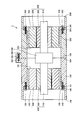
- a power transmission device 1 includes a first rotating electrical machine 100 that extends in the axial direction from a first end surface 191 to a second end surface 192, a first case 160 that houses the first rotating electrical machine 100, A first fixing member 150 for fixing the first rotating electrical machine 100 to the first case 160 on the second end surface 192 side, a second rotating electrical machine 200 extending in the axial direction from the third end surface 293 to the fourth end surface 294, and A second case 260 for housing the two-rotating electric machine 200 and a second fixing member 250 for fixing the second rotating electric machine 200 to the second case 260 on the fourth end face 294 side, and a first end face 191 of the first case 160.
- the power transmission device 1 further includes a third fixing member 350 that joins the flange portion 162 of the first case 160 and the flange portion 262 of the second case 260.
- a first pedestal 140 is interposed between the first rotating electrical machine 100 and the first case 160, and a second pedestal 240 is interposed between the second rotating electrical machine 200 and the second case 260.
- the first case and the second case 160, 260 are cylindrical, and the first and second rotating electrical machines 100, 200 are housed in the internal space.
- Step portions 161 and 261 are formed in the first and second cases 160 and 260, and the first and second pedestals 140 and 240 are in contact with the step portions 161 and 261.
- the first and second cases 160 and 260 are configured by a large-diameter portion having a relatively large inner diameter and a small-diameter portion having a relatively small inner diameter, and the flanges of the first and second pedestals 140 and 240.
- the parts 141 and 241 are located in the large diameter part, and the other parts are located in the small diameter part.
- the inner diameter of the large-diameter portion is substantially constant and the inner diameter of the small-diameter portion is also substantially constant.
- the present invention is not limited to this structure, and an inner peripheral surface of a tapered surface that gradually decreases or expands may be provided. Good.
- the first and second cases 160 and 260 extend from the end surfaces 168 and 268 to the first and second mating surfaces 169 and 269.
- a cylindrical inner peripheral surface is shown, but it is not limited to a cylindrical shape and may be a rectangular tube shape.
- a rib may be provided on a part of the inner peripheral surface of the cylinder, and the rib may extend in the axial direction.
- the first and second fixing members 150 and 250 constituted by bolts are inserted into the through holes 142 and 242 of the first and second bases 140 and 240 and screwed into the first and second cases 160 and 260. . Thereby, the first and second pedestals 140 and 240 can be fixed to the first and second cases 160 and 260.
- first and second fixing members 150 and 250 there are at least three first and second fixing members 150 and 250 arranged on the circumference.
- the first and second rotating electrical machines 100 and 200 are rotatable first and second rotating shafts 110 and 210, and first and second rotors 120 provided on the outer circumferences of the first and second rotating shafts 110 and 210. , 220 and first and second stators 130, 230 arranged to face the first and second rotors 120, 220.
- the first and second rotors 120 and 220 attached to the outer circumferences of the first and second rotating shafts 110 and 210 also rotate.
- the first and second rotors 120 and 220 are opposed to the first and second stators 130 and 230.
- a coil is wound around the stator core.
- the winding method of the coil either distributed winding or concentrated winding can be employed.
- the copper wire constituting the coil may be a round wire or a flat wire.
- the outer peripheral surfaces of the first and second stators 130 and 230 are held by the first and second pedestals 140 and 240.
- Flange portions 162 and 262 are provided on the outer peripheral surfaces of the first and second cases 160 and 260.
- the power transmission device 1 is used as a transmission for a hybrid vehicle incorporating a first rotating electrical machine 100 and a second rotating electrical machine 200 as two rotating electrical machines.
- the first rotating electrical machine 100 and the second rotating electrical machine 200 as a motor / generator are housed in independent first case 160 and second case 260, and are connected to each other to constitute a hybrid vehicle transmission.
- the first stator 130 and the second stator 230 are fastened and fixed to the first case 160 and the second case 260 on the side opposite to the first mating surface 169 and the second mating surface 269.
- the vibration of the first rotating electrical machine 100 is transmitted to the first case 160 via the first fixing member 150.
- vibration near the first mating surface 169 can be suppressed.
- the vibration of the second rotating electrical machine 200 is transmitted to the second case 260 via the second fixing member 250.
- vibration near the second mating surface 269 is suppressed.
- the input of the vibration of the stator to the 1st mating surface 169 and the 2nd mating surface 269 reduces, and the fastening reliability between cases improves.
- FIG. 2 is a cross-sectional view of first and second rotating electric machines as power transmission devices according to Embodiment 2 of the present invention.
- power split mechanism 300 is provided between first rotary shaft 110 and second rotary shaft 210.
- Power split device 300 is constituted by a planetary gear device, for example.
- a power split mechanism 300 is used to distribute power from the engine to travel and power generation by the generator. That is, one of the first rotating shaft 110 and the second rotating shaft 210 is connected to the engine.
- the power split mechanism 300 configured by the planetary gear mechanism is driven, noise and vibration are generated.
- the vibration is reduced to be transmitted to the first mating surface 169 and the second mating surface 269, deformation in the first mating surface 169 and the second mating surface 269 is suppressed. be able to.
- the stress to the power split mechanism 300 is suppressed, and noise and vibration can be reduced.
- SYMBOLS 1 Power transmission device 100 1st rotary electric machine, 110 1st rotary shaft, 120 1st rotor, 130 1st stator, 140 1st base, 141, 162, 262 flange part, 142 through-hole, 150 1st fixing member, 160 1st case, 161 stepped portion, 169 first mating surface, 191 first end surface, 192 second end surface, 200 second rotating electrical machine, 210 second rotating shaft, 230 second stator, 240 second pedestal, 250 second Fixed member, 260 second case, 269 second mating surface, 293 third end surface, 294 fourth end surface, 300 power split mechanism, 350 third fixing member.
Landscapes
- Engineering & Computer Science (AREA)
- Power Engineering (AREA)
- Chemical & Material Sciences (AREA)
- Combustion & Propulsion (AREA)
- Transportation (AREA)
- Mechanical Engineering (AREA)
- Hybrid Electric Vehicles (AREA)
- Motor Or Generator Frames (AREA)
- Connection Of Motors, Electrical Generators, Mechanical Devices, And The Like (AREA)
Abstract
Description
好ましくは、第一回転電機と第一ケースとの間に介在する第一台座と、第二回転電機と第二ケースとの間に介在する第二台座とをさらに備える。
図1は、この発明の実施の形態1に従った動力伝達装置としての第一および第二回転電機の断面図である。図1を参照して、動力伝達装置1は、第一端面191から第二端面192まで軸方向に延在する第一回転電機100と、第一回転電機100を収納する第一ケース160と、第一回転電機100を第二端面192側において第一ケース160に固定する第一固定部材150と、第三端面293から第四端面294まで軸方向に延在する第二回転電機200と、第二回転電機200を収納する第二ケース260と、第二回転電機200を第四端面294側において第二ケース260に固定する第二固定部材250とを備え、第一ケース160の第一端面191側の第一合せ面169と、第二ケース260の第三端面293側の第二合せ面269とが接合されている。また動力伝達装置1は、第一ケース160のフランジ部162と第二ケース260のフランジ部262とを接合する第三固定部材350をさらに備える。第一回転電機100と第一ケース160との間に第一台座140が介在し、第二回転電機200と第二ケース260との間に第二台座240が介在する。
図2は、この発明の実施の形態2に従った動力伝達装置としての第一および第二回転電機の断面図である。図2を参照して、この発明の実施の形態2に従った動力伝達装置1では、第一回転シャフト110と第二回転シャフト210との間に動力分割機構300が設けられている点で、実施の形態1に従った動力伝達装置と異なる。動力分割機構300は、たとえば遊星歯車装置から構成される。エンジンからの動力を走行用とジェネレータの発電用とに振分けるために動力分割機構300が用いられる。すなわち、第一回転シャフト110および第二回転シャフト210のいずれかがエンジンに接続される。遊星歯車機構により構成される動力分割機構300が駆動されるとノイズおよび振動が生じる。しかしながら実施の形態1で示したように、この振動は第一合せ面169および第二合せ面269へ伝えられることが減少するため、第一合せ面169および第二合せ面269における変形を抑制することができる。
Claims (4)
- 第一端面(191)から第二端面(192)まで軸方向に延在する第一回転電機(100)と、
前記第一回転電機を収納する第一ケース(160)と、
前記第一回転電機を前記第二端面側において前記第一ケースに固定する第一固定部材(150)と、
第三端面(293)から第四端面(294)まで軸方向に延在する第二回転電機(200)と、
前記第二回転電機を収納する第二ケース(260)と、
前記第二回転電機を前記第四端面側において前記第二ケースに固定する第二固定部材(250)とを備え、
前記第一ケースの前記第一端面側の面(169)と、前記第二ケースの前記第二端面側の面(269)とが接合される、動力伝達装置。 - 前記第一回転電機と前記第二回転電機とに接続される動力分割機構(300)をさらに備えた、請求項1に記載の動力伝達装置。
- 前記第一および第二ケースを接合する第三固定部材をさらに備えた、請求項1に記載の動力伝達装置。
- 前記第一回転電機と前記第一ケースとの間に介在する第一台座(140)と、前記第二回転電機と前記第二ケースとの間に介在する第二台座(240)とをさらに備えた、請求項1に記載の動力伝達装置。
Priority Applications (5)
| Application Number | Priority Date | Filing Date | Title |
|---|---|---|---|
| JP2013509716A JP5757326B2 (ja) | 2011-04-15 | 2011-04-15 | 動力伝達装置 |
| EP11863397.3A EP2698564B1 (en) | 2011-04-15 | 2011-04-15 | Power transmission device |
| CN201180070007.5A CN103459895B (zh) | 2011-04-15 | 2011-04-15 | 动力传递装置 |
| PCT/JP2011/059353 WO2012140771A1 (ja) | 2011-04-15 | 2011-04-15 | 動力伝達装置 |
| US14/111,320 US9236787B2 (en) | 2011-04-15 | 2011-04-15 | Motive power transmission device |
Applications Claiming Priority (1)
| Application Number | Priority Date | Filing Date | Title |
|---|---|---|---|
| PCT/JP2011/059353 WO2012140771A1 (ja) | 2011-04-15 | 2011-04-15 | 動力伝達装置 |
Publications (1)
| Publication Number | Publication Date |
|---|---|
| WO2012140771A1 true WO2012140771A1 (ja) | 2012-10-18 |
Family
ID=47008973
Family Applications (1)
| Application Number | Title | Priority Date | Filing Date |
|---|---|---|---|
| PCT/JP2011/059353 Ceased WO2012140771A1 (ja) | 2011-04-15 | 2011-04-15 | 動力伝達装置 |
Country Status (5)
| Country | Link |
|---|---|
| US (1) | US9236787B2 (ja) |
| EP (1) | EP2698564B1 (ja) |
| JP (1) | JP5757326B2 (ja) |
| CN (1) | CN103459895B (ja) |
| WO (1) | WO2012140771A1 (ja) |
Cited By (1)
| Publication number | Priority date | Publication date | Assignee | Title |
|---|---|---|---|---|
| JP2020150643A (ja) * | 2019-03-12 | 2020-09-17 | 本田技研工業株式会社 | モータユニットおよびモータユニットの製造方法 |
Families Citing this family (8)
| Publication number | Priority date | Publication date | Assignee | Title |
|---|---|---|---|---|
| JP6078486B2 (ja) * | 2014-02-17 | 2017-02-08 | 本田技研工業株式会社 | 駆動装置のケース構造 |
| ES2770598T3 (es) * | 2014-08-22 | 2020-07-02 | Weg Equipamentos Electricos S A | Carcasa para una máquina eléctrica rotatoria |
| JP2016048099A (ja) * | 2014-08-28 | 2016-04-07 | ナブテスコ株式会社 | 偏心揺動型歯車装置及びそのトルク調整方法 |
| CN104779733B (zh) * | 2015-03-26 | 2017-11-10 | 中国石油天然气股份有限公司 | 一种潜油电机 |
| EP3540918A1 (de) * | 2018-03-13 | 2019-09-18 | FLET GmbH | Elektrofahrzeug |
| US10804766B1 (en) * | 2019-04-11 | 2020-10-13 | Ford Global Technologies, Llc | Hybrid/electric vehicle transmission |
| CN111546867A (zh) * | 2020-06-04 | 2020-08-18 | 江苏途跃特种车技术有限公司 | 一种异型双动力全时同步四驱动力总成 |
| CN113708539B (zh) * | 2021-10-28 | 2022-02-08 | 南昌耀德精密五金有限公司 | 一种电机外壳及电机定子结构 |
Citations (5)
| Publication number | Priority date | Publication date | Assignee | Title |
|---|---|---|---|---|
| JP2007015441A (ja) * | 2005-07-05 | 2007-01-25 | Aisin Aw Co Ltd | ハイブリッド車用駆動装置 |
| JP2008515726A (ja) * | 2004-09-27 | 2008-05-15 | マグナ・シユタイル・フアールツオイクテヒニク・アクチエンゲゼルシヤフト・ウント・コンパニー・コマンデイトゲゼルシヤフト | 縦配置のハイブリッド駆動装置を持つ自動車用駆動単位 |
| JP2008265517A (ja) | 2007-04-19 | 2008-11-06 | Toyota Motor Corp | 車両用動力伝達装置 |
| JP2009149114A (ja) | 2007-12-18 | 2009-07-09 | Toyota Motor Corp | 駆動装置 |
| JP2010195338A (ja) * | 2009-02-27 | 2010-09-09 | Honda Motor Co Ltd | ハイブリッド車両用駆動装置 |
Family Cites Families (12)
| Publication number | Priority date | Publication date | Assignee | Title |
|---|---|---|---|---|
| DE4323599C1 (de) * | 1993-07-09 | 1994-10-27 | Mannesmann Ag | Antriebseinheit |
| EP1918150B1 (en) * | 2001-12-26 | 2012-11-21 | Toyota Jidosha Kabushiki Kaisha | Drive apparatus for hybrid vehicle |
| US7002267B2 (en) * | 2004-03-22 | 2006-02-21 | General Motors Corporation | Method and apparatus for cooling a hybrid transmission electric motor |
| US7586225B2 (en) * | 2004-03-22 | 2009-09-08 | Gm Global Technology Operations, Inc. | Hybrid transmission motor module with integral wire connections |
| JP4687003B2 (ja) * | 2004-04-21 | 2011-05-25 | トヨタ自動車株式会社 | 回転部材の支持構造および動力機構 |
| US7339300B2 (en) * | 2004-07-28 | 2008-03-04 | Gm Global Technology Operations, Inc. | Structural support member for stator retention and method of assembling an electromechanical transmission |
| WO2006090484A1 (ja) | 2005-02-24 | 2006-08-31 | Toyota Jidosha Kabushiki Kaisha | 回転電機を有する駆動装置 |
| JP4341577B2 (ja) * | 2005-04-25 | 2009-10-07 | トヨタ自動車株式会社 | 車両駆動装置 |
| CN100581863C (zh) * | 2005-06-27 | 2010-01-20 | 丰田自动车株式会社 | 混合动力车辆的动力传递装置 |
| JP4258556B2 (ja) * | 2007-03-24 | 2009-04-30 | トヨタ自動車株式会社 | ハイブリッド車両用駆動装置の制御装置 |
| JP2009142031A (ja) | 2007-12-05 | 2009-06-25 | Aisin Seiki Co Ltd | 回転電機用ステータ |
| JP2010114951A (ja) * | 2008-11-04 | 2010-05-20 | Toyota Motor Corp | モータ |
-
2011
- 2011-04-15 US US14/111,320 patent/US9236787B2/en active Active
- 2011-04-15 WO PCT/JP2011/059353 patent/WO2012140771A1/ja not_active Ceased
- 2011-04-15 EP EP11863397.3A patent/EP2698564B1/en active Active
- 2011-04-15 CN CN201180070007.5A patent/CN103459895B/zh active Active
- 2011-04-15 JP JP2013509716A patent/JP5757326B2/ja active Active
Patent Citations (5)
| Publication number | Priority date | Publication date | Assignee | Title |
|---|---|---|---|---|
| JP2008515726A (ja) * | 2004-09-27 | 2008-05-15 | マグナ・シユタイル・フアールツオイクテヒニク・アクチエンゲゼルシヤフト・ウント・コンパニー・コマンデイトゲゼルシヤフト | 縦配置のハイブリッド駆動装置を持つ自動車用駆動単位 |
| JP2007015441A (ja) * | 2005-07-05 | 2007-01-25 | Aisin Aw Co Ltd | ハイブリッド車用駆動装置 |
| JP2008265517A (ja) | 2007-04-19 | 2008-11-06 | Toyota Motor Corp | 車両用動力伝達装置 |
| JP2009149114A (ja) | 2007-12-18 | 2009-07-09 | Toyota Motor Corp | 駆動装置 |
| JP2010195338A (ja) * | 2009-02-27 | 2010-09-09 | Honda Motor Co Ltd | ハイブリッド車両用駆動装置 |
Non-Patent Citations (1)
| Title |
|---|
| See also references of EP2698564A4 * |
Cited By (2)
| Publication number | Priority date | Publication date | Assignee | Title |
|---|---|---|---|---|
| JP2020150643A (ja) * | 2019-03-12 | 2020-09-17 | 本田技研工業株式会社 | モータユニットおよびモータユニットの製造方法 |
| JP7280721B2 (ja) | 2019-03-12 | 2023-05-24 | 本田技研工業株式会社 | モータユニットおよびモータユニットの製造方法 |
Also Published As
| Publication number | Publication date |
|---|---|
| CN103459895B (zh) | 2016-09-07 |
| EP2698564A4 (en) | 2015-12-30 |
| JP5757326B2 (ja) | 2015-07-29 |
| JPWO2012140771A1 (ja) | 2014-07-28 |
| EP2698564B1 (en) | 2017-03-15 |
| CN103459895A (zh) | 2013-12-18 |
| EP2698564A1 (en) | 2014-02-19 |
| US20140035415A1 (en) | 2014-02-06 |
| US9236787B2 (en) | 2016-01-12 |
Similar Documents
| Publication | Publication Date | Title |
|---|---|---|
| JP5757326B2 (ja) | 動力伝達装置 | |
| JP5488614B2 (ja) | ステータコアの固定構造およびそれを備えた回転電機 | |
| JP5779947B2 (ja) | ハイブリッド建設機械 | |
| CN102545467B (zh) | 旋转电机、机器人、旋转电机的制造方法、中空轴 | |
| WO2012073959A1 (ja) | ステータ | |
| CN104852501B (zh) | 驱动装置的壳体结构 | |
| US12003165B2 (en) | Motor case | |
| JP2010124661A (ja) | 回転電機 | |
| JP5326432B2 (ja) | 回転電機のステータ固定構造 | |
| JP2010221775A (ja) | ハイブリッド車用動力伝達装置 | |
| JP5466117B2 (ja) | 電動機のステータの製造方法および固定子用コイルの位置決め方法 | |
| JP2014126048A (ja) | ギア及び該ギアを用いた電動機 | |
| JP2020078099A (ja) | 回転電機 | |
| JP5957366B2 (ja) | 回転電機のステータ | |
| WO2019026423A1 (ja) | 構造体、ステータ、およびモータ | |
| JP2016005415A (ja) | 回転電機のロータ | |
| JP2011091963A (ja) | レゾルバの固定構造 | |
| JP6751325B2 (ja) | 軸受構造 | |
| JP2016032355A (ja) | 回転電機のステータ | |
| JP2016194286A (ja) | 回転電機の回転子の絶縁スペーサ | |
| JP2018129937A (ja) | 回転電機 | |
| JP2018098943A (ja) | 回転電機及び回転電機の製造方法 | |
| JP6523403B1 (ja) | 回転電機 | |
| WO2023074188A1 (ja) | モータ、多関節ロボット及び無人航空機 | |
| JP2025058490A (ja) | ロータ、および回転電機、および駆動装置 |
Legal Events
| Date | Code | Title | Description |
|---|---|---|---|
| 121 | Ep: the epo has been informed by wipo that ep was designated in this application |
Ref document number: 11863397 Country of ref document: EP Kind code of ref document: A1 |
|
| ENP | Entry into the national phase |
Ref document number: 2013509716 Country of ref document: JP Kind code of ref document: A |
|
| WWE | Wipo information: entry into national phase |
Ref document number: 14111320 Country of ref document: US |
|
| NENP | Non-entry into the national phase |
Ref country code: DE |
|
| REEP | Request for entry into the european phase |
Ref document number: 2011863397 Country of ref document: EP |
|
| WWE | Wipo information: entry into national phase |
Ref document number: 2011863397 Country of ref document: EP |