WO2012140784A1 - 内燃機関の排気浄化装置 - Google Patents
内燃機関の排気浄化装置 Download PDFInfo
- Publication number
- WO2012140784A1 WO2012140784A1 PCT/JP2011/059880 JP2011059880W WO2012140784A1 WO 2012140784 A1 WO2012140784 A1 WO 2012140784A1 JP 2011059880 W JP2011059880 W JP 2011059880W WO 2012140784 A1 WO2012140784 A1 WO 2012140784A1
- Authority
- WO
- WIPO (PCT)
- Prior art keywords
- exhaust
- purification
- catalyst
- hydrocarbons
- purification catalyst
- Prior art date
- Legal status (The legal status is an assumption and is not a legal conclusion. Google has not performed a legal analysis and makes no representation as to the accuracy of the status listed.)
- Ceased
Links
Images













Classifications
-
- B—PERFORMING OPERATIONS; TRANSPORTING
- B01—PHYSICAL OR CHEMICAL PROCESSES OR APPARATUS IN GENERAL
- B01D—SEPARATION
- B01D53/00—Separation of gases or vapours; Recovering vapours of volatile solvents from gases; Chemical or biological purification of waste gases, e.g. engine exhaust gases, smoke, fumes, flue gases, aerosols
- B01D53/34—Chemical or biological purification of waste gases
- B01D53/92—Chemical or biological purification of waste gases of engine exhaust gases
- B01D53/94—Chemical or biological purification of waste gases of engine exhaust gases by catalytic processes
- B01D53/9404—Removing only nitrogen compounds
- B01D53/9409—Nitrogen oxides
- B01D53/9431—Processes characterised by a specific device
-
- F—MECHANICAL ENGINEERING; LIGHTING; HEATING; WEAPONS; BLASTING
- F01—MACHINES OR ENGINES IN GENERAL; ENGINE PLANTS IN GENERAL; STEAM ENGINES
- F01N—GAS-FLOW SILENCERS OR EXHAUST APPARATUS FOR MACHINES OR ENGINES IN GENERAL; GAS-FLOW SILENCERS OR EXHAUST APPARATUS FOR INTERNAL-COMBUSTION ENGINES
- F01N3/00—Exhaust or silencing apparatus having means for purifying, rendering innocuous, or otherwise treating exhaust
- F01N3/02—Exhaust or silencing apparatus having means for purifying, rendering innocuous, or otherwise treating exhaust for cooling, or for removing solid constituents of, exhaust
- F01N3/021—Exhaust or silencing apparatus having means for purifying, rendering innocuous, or otherwise treating exhaust for cooling, or for removing solid constituents of, exhaust by means of filters
- F01N3/033—Exhaust or silencing apparatus having means for purifying, rendering innocuous, or otherwise treating exhaust for cooling, or for removing solid constituents of, exhaust by means of filters in combination with other devices
- F01N3/035—Exhaust or silencing apparatus having means for purifying, rendering innocuous, or otherwise treating exhaust for cooling, or for removing solid constituents of, exhaust by means of filters in combination with other devices with catalytic reactors
-
- F—MECHANICAL ENGINEERING; LIGHTING; HEATING; WEAPONS; BLASTING
- F01—MACHINES OR ENGINES IN GENERAL; ENGINE PLANTS IN GENERAL; STEAM ENGINES
- F01N—GAS-FLOW SILENCERS OR EXHAUST APPARATUS FOR MACHINES OR ENGINES IN GENERAL; GAS-FLOW SILENCERS OR EXHAUST APPARATUS FOR INTERNAL-COMBUSTION ENGINES
- F01N3/00—Exhaust or silencing apparatus having means for purifying, rendering innocuous, or otherwise treating exhaust
- F01N3/08—Exhaust or silencing apparatus having means for purifying, rendering innocuous, or otherwise treating exhaust for rendering innocuous
- F01N3/0807—Exhaust or silencing apparatus having means for purifying, rendering innocuous, or otherwise treating exhaust for rendering innocuous by using absorbents or adsorbents
- F01N3/0828—Exhaust or silencing apparatus having means for purifying, rendering innocuous, or otherwise treating exhaust for rendering innocuous by using absorbents or adsorbents characterised by the absorbed or adsorbed substances
- F01N3/0842—Nitrogen oxides
-
- F—MECHANICAL ENGINEERING; LIGHTING; HEATING; WEAPONS; BLASTING
- F01—MACHINES OR ENGINES IN GENERAL; ENGINE PLANTS IN GENERAL; STEAM ENGINES
- F01N—GAS-FLOW SILENCERS OR EXHAUST APPARATUS FOR MACHINES OR ENGINES IN GENERAL; GAS-FLOW SILENCERS OR EXHAUST APPARATUS FOR INTERNAL-COMBUSTION ENGINES
- F01N3/00—Exhaust or silencing apparatus having means for purifying, rendering innocuous, or otherwise treating exhaust
- F01N3/08—Exhaust or silencing apparatus having means for purifying, rendering innocuous, or otherwise treating exhaust for rendering innocuous
- F01N3/0807—Exhaust or silencing apparatus having means for purifying, rendering innocuous, or otherwise treating exhaust for rendering innocuous by using absorbents or adsorbents
- F01N3/0871—Exhaust or silencing apparatus having means for purifying, rendering innocuous, or otherwise treating exhaust for rendering innocuous by using absorbents or adsorbents using means for controlling, e.g. purging, the absorbents or adsorbents
-
- F—MECHANICAL ENGINEERING; LIGHTING; HEATING; WEAPONS; BLASTING
- F01—MACHINES OR ENGINES IN GENERAL; ENGINE PLANTS IN GENERAL; STEAM ENGINES
- F01N—GAS-FLOW SILENCERS OR EXHAUST APPARATUS FOR MACHINES OR ENGINES IN GENERAL; GAS-FLOW SILENCERS OR EXHAUST APPARATUS FOR INTERNAL-COMBUSTION ENGINES
- F01N3/00—Exhaust or silencing apparatus having means for purifying, rendering innocuous, or otherwise treating exhaust
- F01N3/08—Exhaust or silencing apparatus having means for purifying, rendering innocuous, or otherwise treating exhaust for rendering innocuous
- F01N3/10—Exhaust or silencing apparatus having means for purifying, rendering innocuous, or otherwise treating exhaust for rendering innocuous by thermal or catalytic conversion of noxious components of exhaust
- F01N3/18—Exhaust or silencing apparatus having means for purifying, rendering innocuous, or otherwise treating exhaust for rendering innocuous by thermal or catalytic conversion of noxious components of exhaust characterised by methods of operation; Control
- F01N3/20—Exhaust or silencing apparatus having means for purifying, rendering innocuous, or otherwise treating exhaust for rendering innocuous by thermal or catalytic conversion of noxious components of exhaust characterised by methods of operation; Control specially adapted for catalytic conversion
- F01N3/206—Adding periodically or continuously substances to exhaust gases for promoting purification, e.g. catalytic material in liquid form, NOx reducing agents
-
- F—MECHANICAL ENGINEERING; LIGHTING; HEATING; WEAPONS; BLASTING
- F01—MACHINES OR ENGINES IN GENERAL; ENGINE PLANTS IN GENERAL; STEAM ENGINES
- F01N—GAS-FLOW SILENCERS OR EXHAUST APPARATUS FOR MACHINES OR ENGINES IN GENERAL; GAS-FLOW SILENCERS OR EXHAUST APPARATUS FOR INTERNAL-COMBUSTION ENGINES
- F01N2240/00—Combination or association of two or more different exhaust treating devices, or of at least one such device with an auxiliary device, not covered by indexing codes F01N2230/00 or F01N2250/00, one of the devices being
- F01N2240/30—Combination or association of two or more different exhaust treating devices, or of at least one such device with an auxiliary device, not covered by indexing codes F01N2230/00 or F01N2250/00, one of the devices being a fuel reformer
-
- F—MECHANICAL ENGINEERING; LIGHTING; HEATING; WEAPONS; BLASTING
- F01—MACHINES OR ENGINES IN GENERAL; ENGINE PLANTS IN GENERAL; STEAM ENGINES
- F01N—GAS-FLOW SILENCERS OR EXHAUST APPARATUS FOR MACHINES OR ENGINES IN GENERAL; GAS-FLOW SILENCERS OR EXHAUST APPARATUS FOR INTERNAL-COMBUSTION ENGINES
- F01N2510/00—Surface coverings
- F01N2510/06—Surface coverings for exhaust purification, e.g. catalytic reaction
-
- F—MECHANICAL ENGINEERING; LIGHTING; HEATING; WEAPONS; BLASTING
- F01—MACHINES OR ENGINES IN GENERAL; ENGINE PLANTS IN GENERAL; STEAM ENGINES
- F01N—GAS-FLOW SILENCERS OR EXHAUST APPARATUS FOR MACHINES OR ENGINES IN GENERAL; GAS-FLOW SILENCERS OR EXHAUST APPARATUS FOR INTERNAL-COMBUSTION ENGINES
- F01N2570/00—Exhaust treating apparatus eliminating, absorbing or adsorbing specific elements or compounds
- F01N2570/14—Nitrogen oxides
-
- F—MECHANICAL ENGINEERING; LIGHTING; HEATING; WEAPONS; BLASTING
- F01—MACHINES OR ENGINES IN GENERAL; ENGINE PLANTS IN GENERAL; STEAM ENGINES
- F01N—GAS-FLOW SILENCERS OR EXHAUST APPARATUS FOR MACHINES OR ENGINES IN GENERAL; GAS-FLOW SILENCERS OR EXHAUST APPARATUS FOR INTERNAL-COMBUSTION ENGINES
- F01N2610/00—Adding substances to exhaust gases
- F01N2610/03—Adding substances to exhaust gases the substance being hydrocarbons, e.g. engine fuel
-
- F—MECHANICAL ENGINEERING; LIGHTING; HEATING; WEAPONS; BLASTING
- F01—MACHINES OR ENGINES IN GENERAL; ENGINE PLANTS IN GENERAL; STEAM ENGINES
- F01N—GAS-FLOW SILENCERS OR EXHAUST APPARATUS FOR MACHINES OR ENGINES IN GENERAL; GAS-FLOW SILENCERS OR EXHAUST APPARATUS FOR INTERNAL-COMBUSTION ENGINES
- F01N2900/00—Details of electrical control or of the monitoring of the exhaust gas treating apparatus
- F01N2900/06—Parameters used for exhaust control or diagnosing
- F01N2900/16—Parameters used for exhaust control or diagnosing said parameters being related to the exhaust apparatus, e.g. particulate filter or catalyst
- F01N2900/1602—Temperature of exhaust gas apparatus
-
- F—MECHANICAL ENGINEERING; LIGHTING; HEATING; WEAPONS; BLASTING
- F01—MACHINES OR ENGINES IN GENERAL; ENGINE PLANTS IN GENERAL; STEAM ENGINES
- F01N—GAS-FLOW SILENCERS OR EXHAUST APPARATUS FOR MACHINES OR ENGINES IN GENERAL; GAS-FLOW SILENCERS OR EXHAUST APPARATUS FOR INTERNAL-COMBUSTION ENGINES
- F01N2900/00—Details of electrical control or of the monitoring of the exhaust gas treating apparatus
- F01N2900/06—Parameters used for exhaust control or diagnosing
- F01N2900/16—Parameters used for exhaust control or diagnosing said parameters being related to the exhaust apparatus, e.g. particulate filter or catalyst
- F01N2900/1614—NOx amount trapped in catalyst
-
- Y—GENERAL TAGGING OF NEW TECHNOLOGICAL DEVELOPMENTS; GENERAL TAGGING OF CROSS-SECTIONAL TECHNOLOGIES SPANNING OVER SEVERAL SECTIONS OF THE IPC; TECHNICAL SUBJECTS COVERED BY FORMER USPC CROSS-REFERENCE ART COLLECTIONS [XRACs] AND DIGESTS
- Y02—TECHNOLOGIES OR APPLICATIONS FOR MITIGATION OR ADAPTATION AGAINST CLIMATE CHANGE
- Y02A—TECHNOLOGIES FOR ADAPTATION TO CLIMATE CHANGE
- Y02A50/00—TECHNOLOGIES FOR ADAPTATION TO CLIMATE CHANGE in human health protection, e.g. against extreme weather
- Y02A50/20—Air quality improvement or preservation, e.g. vehicle emission control or emission reduction by using catalytic converters
Definitions
- the present invention relates to an exhaust purification device for an internal combustion engine.
- An internal combustion engine in which the air-fuel ratio of the exhaust gas flowing into the NO x storage catalyst is made rich is known (see, for example, Patent Document 1).
- An object of the present invention is to provide an exhaust purification device for an internal combustion engine that can obtain a high NO x purification rate even when the temperature of the exhaust purification catalyst becomes high.
- a hydrocarbon supply valve for supplying hydrocarbons is disposed in the engine exhaust passage, and reformed with NO x contained in the exhaust gas in the engine exhaust passage downstream of the hydrocarbon supply valve.
- An exhaust purification catalyst for reacting with hydrocarbons is disposed, and a noble metal catalyst is supported on the exhaust gas flow surface of the exhaust purification catalyst, and a basic exhaust gas flow surface portion is formed around the noble metal catalyst.
- an exhaust gas purification apparatus for an internal combustion engine in which NO x stored in the exhaust gas purification catalyst and NO x stored in the exhaust gas purification catalyst are reduced.
- FIG. 1 is an overall view of a compression ignition type internal combustion engine.
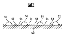
- FIG. 2 is a view schematically showing the surface portion of the catalyst carrier.
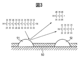
- FIG. 3 is a view for explaining an oxidation reaction in the exhaust purification catalyst.
- FIG. 4 is a diagram showing changes in the air-fuel ratio of the exhaust gas flowing into the exhaust purification catalyst.
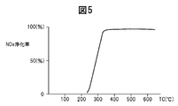
- Figure 5 is a diagram showing the NO x purification rate.
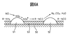
- 6A and 6B are diagrams for explaining the oxidation-reduction reaction in the exhaust purification catalyst.
- 7A and 7B are diagrams for explaining the oxidation-reduction reaction in the exhaust purification catalyst.
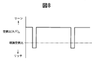
- FIG. 8 is a diagram schematically showing a change in the air-fuel ratio of the exhaust gas flowing into the exhaust purification catalyst.
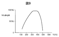
- FIG. 9 is a diagram showing the NO x purification rate.
- FIG. 10 is a time chart showing changes in the air-fuel ratio of the exhaust gas flowing into the exhaust purification catalyst.
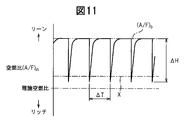
- FIG. 11 is a time chart showing changes in the air-fuel ratio of the exhaust gas flowing into the exhaust purification catalyst.
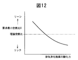
- FIG. 12 is a diagram showing the relationship between the oxidizing power of the exhaust purification catalyst and the required minimum air-fuel ratio X.
- FIG. 13 is a diagram showing the relationship between the oxygen concentration in the exhaust gas and the amplitude ⁇ H of the hydrocarbon concentration, with which the same NO x purification rate can be obtained.
- Figure 14 is a diagram showing a relationship between an amplitude ⁇ H and the NO x purification rate of the hydrocarbon concentration.
- FIG. 10 is a time chart showing changes in the air-fuel ratio of the exhaust gas flowing into the exhaust purification catalyst.
- FIG. 11 is a time chart showing changes in the air-fuel ratio of the exhaust gas flowing into the exhaust purification catalyst.
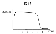
- FIG. 15 is a graph showing the relationship between the vibration period ⁇ T of the hydrocarbon concentration and the NO x purification rate.
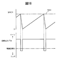
- FIG. 16 is a diagram schematically showing changes in the air-fuel ratio of exhaust gas flowing into the exhaust purification catalyst.
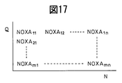
- Figure 17 is a diagram illustrating a map of exhaust NO x amount NOXA.
- FIG. 18 is a diagram showing the fuel injection timing.
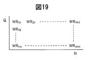
- FIG. 19 is a diagram showing a map of the hydrocarbon supply amount WR.
- FIG. 20 is a diagram showing a hydrocarbon injection pattern from a hydrocarbon feed valve, a change in hydrocarbon concentration in exhaust gas flowing into the exhaust purification catalyst, and the like.
- FIG. 21 is a diagram showing a hydrocarbon injection pattern from a hydrocarbon supply valve and a change in hydrocarbon concentration in exhaust gas flowing into the exhaust purification catalyst.
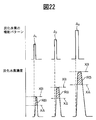
- FIG. 22 is a diagram showing a hydrocarbon injection pattern from a hydrocarbon feed valve and a change in hydrocarbon concentration in exhaust gas flowing into the exhaust purification catalyst.
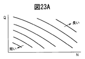
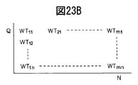
- FIGS. 23A to 23C are views showing a hydrocarbon injection time and the like.
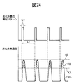
- FIG. 24 is a diagram showing a hydrocarbon injection pattern from a hydrocarbon feed valve and a change in hydrocarbon concentration in exhaust gas flowing into the exhaust purification catalyst.
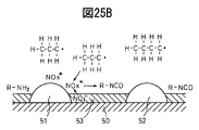
- 25A and 25B are views for explaining the behavior of the absorbing NO x.
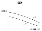
- FIG. 26 is a diagram showing the NO x release temperature TC1 and the boundary temperature TC2.
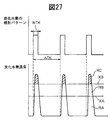
- FIG. 27 is a diagram showing a hydrocarbon injection pattern from a hydrocarbon feed valve and a change in hydrocarbon concentration in exhaust gas flowing into the exhaust purification catalyst.
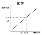
- FIG. 28 is a diagram showing the relationship between the hydrocarbon injection time and the injection cycle.
- FIG. 29 is a diagram showing a change in the air-fuel ratio of the exhaust gas flowing into the exhaust purification catalyst.
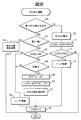
- FIG. 30 is a flowchart for performing NO x purification control.
- Fig. 1 shows an overall view of a compression ignition type internal combustion engine.
- 1 is an engine body
- 2 is a combustion chamber of each cylinder
- 3 is an electronically controlled fuel injection valve for injecting fuel into each combustion chamber
- 4 is an intake manifold
- 5 is an exhaust manifold.
- the intake manifold 4 is connected to the outlet of the compressor 7 a of the exhaust turbocharger 7 via the intake duct 6, and the inlet of the compressor 7 a is connected to the air cleaner 9 via the intake air amount detector 8.
- a throttle valve 10 driven by a step motor is disposed in the intake duct 6, and a cooling device 11 for cooling intake air flowing through the intake duct 6 is disposed around the intake duct 6.
- a cooling device 11 for cooling intake air flowing through the intake duct 6 is disposed around the intake duct 6.
- the engine cooling water is guided into the cooling device 11, and the intake air is cooled by the engine cooling water.
- the exhaust manifold 5 is connected to the inlet of the exhaust turbine 7 b of the exhaust turbocharger 7.
- the outlet of the exhaust turbine 7b is connected to the inlet of the exhaust purification catalyst 13 via the exhaust pipe 12, and the outlet of the exhaust purification catalyst 13 is connected to the particulate filter 14 for collecting particulates contained in the exhaust gas. Is done.
- a hydrocarbon supply valve 15 for supplying hydrocarbons composed of light oil and other fuels used as fuel for the compression ignition internal combustion engine is disposed in the embodiment shown in FIG. 1, light oil is used as the hydrocarbon supplied from the hydrocarbon supply valve 15.
- the present invention can also be applied to a spark ignition type internal combustion engine in which combustion is performed under a lean air-fuel ratio.
- the hydrocarbon supply valve 15 supplies hydrocarbons made of gasoline or other fuel used as fuel for the spark ignition internal combustion engine.
- the exhaust manifold 5 and the intake manifold 4 are connected to each other via an exhaust gas recirculation (hereinafter referred to as EGR) passage 16, and an electronically controlled EGR control valve 17 is disposed in the EGR passage 16.
- EGR exhaust gas recirculation
- a cooling device 18 for cooling the EGR gas flowing in the EGR passage 16 is disposed around the EGR passage 16. In the embodiment shown in FIG. 1, the engine cooling water is guided into the cooling device 18, and the EGR gas is cooled by the engine cooling water.
- each fuel injection valve 3 is connected to a common rail 20 via a fuel supply pipe 19, and this common rail 20 is connected to a fuel tank 22 via an electronically controlled fuel pump 21 having a variable discharge amount.
- the fuel stored in the fuel tank 22 is supplied into the common rail 20 by the fuel pump 21, and the fuel supplied into the common rail 20 is supplied to the fuel injection valve 3 through each fuel supply pipe 19.
- the electronic control unit 30 is composed of a digital computer, and is connected to each other by a bidirectional bus 31.
- a temperature sensor 23 for detecting the temperature of the exhaust purification catalyst 13 is attached downstream of the exhaust purification catalyst 13.
- the particulate filter 14 is provided with a differential pressure sensor 24 for detecting a differential pressure before and after the particulate filter 14.
- Output signals of the temperature sensor 23, the differential pressure sensor 24, and the intake air amount detector 8 are input to the input port 35 via corresponding AD converters 37, respectively.
- a load sensor 41 that generates an output voltage proportional to the depression amount L of the accelerator pedal 40 is connected to the accelerator pedal 40, and the output voltage of the load sensor 41 is input to the input port 35 via the corresponding AD converter 37. Is done.
- the input port 35 is connected to a crank angle sensor 42 that generates an output pulse every time the crankshaft rotates, for example, 15 °.
- FIG. 2 schematically shows the surface portion of the catalyst carrier carried on the substrate of the exhaust purification catalyst 13.
- noble metal catalysts 51 and 52 are supported on a catalyst support 50 made of alumina, for example, and further on this catalyst support 50 potassium K, sodium Na, cesium Cs.
- Alkaline metals such as barium Ba, alkaline earth metals such as calcium Ca, rare earths such as lanthanoids and silver Ag, copper Cu, iron Fe, NO such as iridium Ir x
- a basic layer 53 containing at least one selected from metals capable of donating electrons is formed. Since the exhaust gas flows along the catalyst carrier 50, it can be said that the noble metal catalysts 51 and 52 are supported on the exhaust gas flow surface of the exhaust purification catalyst 13. Further, since the surface of the basic layer 53 is basic, the surface of the basic layer 53 is referred to as a basic exhaust gas flow surface portion 54.
- the noble metal catalyst 51 is made of platinum Pt, and the noble metal catalyst 52 is made of rhodium Rh.
- the noble metal catalysts 51 and 52 carried on the catalyst carrier 50 are composed of platinum Pt and rhodium Rh.
- palladium Pd can be further supported on the catalyst carrier 50 of the exhaust purification catalyst 13, or palladium Pd can be supported instead of rhodium Rh.
- the noble metal catalysts 51 and 52 supported on the catalyst carrier 50 are composed of platinum Pt and at least one of rhodium Rh and palladium Pd.
- FIG. 3 schematically shows the reforming action performed in the exhaust purification catalyst 13 at this time.
- the hydrocarbon HC injected from the hydrocarbon feed valve 15 is converted into a radical hydrocarbon HC having a small number of carbons by the catalyst 51.
- FIG. 4 shows the supply timing of hydrocarbons from the hydrocarbon supply valve 15 and the change in the air-fuel ratio (A / F) in of the exhaust gas flowing into the exhaust purification catalyst 13. Since the change in the air-fuel ratio (A / F) in depends on the change in the concentration of hydrocarbons in the exhaust gas flowing into the exhaust purification catalyst 13, the air-fuel ratio (A / F) in shown in FIG. It can be said that the change represents a change in hydrocarbon concentration.
- FIG. 5 shows a change in the air-fuel ratio (A / F) in of the exhaust gas flowing into the exhaust purification catalyst 13 as shown in FIG. 4 by periodically changing the concentration of hydrocarbons flowing into the exhaust purification catalyst 13. NO by the exhaust purification catalyst 13 when x The purification rate is shown for each catalyst temperature TC of the exhaust purification catalyst 13. The inventor has NO over a long period of time.
- FIG. 6A and 6B In the research course, when the concentration of hydrocarbons flowing into the exhaust purification catalyst 13 is vibrated with an amplitude within a predetermined range and a period within a predetermined range, FIG. As shown in Fig. 4, extremely high NO even in a high temperature region of 400 ° C or higher. x It has been found that a purification rate can be obtained. Further, at this time, a large amount of the reducing intermediate containing nitrogen and hydrocarbon continues to be held or adsorbed on the surface of the basic layer 53, that is, on the basic exhaust gas flow surface portion 54 of the exhaust purification catalyst 13. Reducing intermediate is high NO x It turns out that it plays a central role in obtaining the purification rate. Next, this will be described with reference to FIGS. 6A and 6B.
- FIGS. 6A and 6B schematically show the surface portion of the catalyst carrier 50 of the exhaust purification catalyst 13, and in these FIGS. 6A and 6B, the concentration of hydrocarbons flowing into the exhaust purification catalyst 13 is predetermined. Shown is a reaction that is presumed to occur when oscillated with an amplitude within a range and a period within a predetermined range.
- FIG. 6A shows a case where the concentration of hydrocarbons flowing into the exhaust purification catalyst 13 is low
- FIG. 6B shows that the concentration of hydrocarbons flowing into the exhaust purification catalyst 13 when hydrocarbons are supplied from the hydrocarbon supply valve 15 is high. It shows when As can be seen from FIG.
- the first reducing intermediate produced at this time is the nitro compound R-NO. 2 It is thought that.
- This nitro compound R-NO 2 Is produced, it becomes a nitrile compound R-CN, but this nitrile compound R-CN can only survive for a moment in that state, so it immediately becomes an isocyanate compound R-NCO.
- this isocyanate compound R-NCO is hydrolyzed, the amine compound R-NH 2 It becomes. However, in this case, it is considered that a part of the isocyanate compound R-NCO is hydrolyzed. Therefore, as shown in FIG.
- Active NO at this time x * Is a reducing intermediate R-NCO or R-NH 2 Reacts with N 2 , CO 2 , H 2 O, so NO x Will be purified.
- a reducing intermediate is generated by increasing the concentration of hydrocarbons flowing into the exhaust purification catalyst 13, and the concentration of hydrocarbons flowing into the exhaust purification catalyst 13 is decreased to reduce the oxygen concentration.
- the exhaust purification catalyst 13 makes NO. x In order to purify, it is necessary to periodically change the concentration of hydrocarbons flowing into the exhaust purification catalyst 13.
- the produced reducing intermediate is activated NO. x * It is necessary to reduce the hydrocarbon concentration to a concentration low enough to react with. That is, it is necessary to vibrate the hydrocarbon concentration flowing into the exhaust purification catalyst 13 with an amplitude within a predetermined range.
- the generated reducing intermediate is active NO. x * Sufficient amounts of reducing intermediates R-NCO and R-NH until 2 Must be retained on the basic layer 53, that is, on the basic exhaust gas flow surface portion 24.
- a basic exhaust gas flow surface portion 24 is provided.
- the injection interval is 3 seconds.
- the oscillation period of hydrocarbon concentration that is, the supply period of hydrocarbon HC is longer than the period within the above-mentioned predetermined range
- the reducing intermediates R-NCO and R-NH are formed on the surface of the basic layer 53. 2 Disappears, and at this time, the active NO produced on platinum Pt53 x * Is nitrate ion NO as shown in FIG. 7A. 3 ⁇ In the form of nitrate in the form of nitrate. That is, at this time, NO in the exhaust gas x Will be absorbed in the basic layer 53 in the form of nitrate.
- FIG. 1 In the form of nitrate in the form of nitrate. That is, at this time, NO in the exhaust gas x Will be absorbed in the basic layer 53 in the form of nitrate.
- x NO for temporary storage x It plays the role of a storage agent. That is, in this case, if the ratio of air and fuel (hydrocarbon) supplied into the engine intake passage, the combustion chamber 2 and the exhaust passage upstream of the exhaust purification catalyst 13 is referred to as the air-fuel ratio of the exhaust gas, the exhaust purification catalyst. 13 is NO when the air-fuel ratio of the exhaust gas is lean x NO is stored when the oxygen concentration in the exhaust gas decreases. x NO release x It functions as a storage catalyst. FIG. 9 shows that the exhaust purification catalyst 13 is NO in this way.
- the purification rate is shown.
- the horizontal axis in FIG. 9 indicates the catalyst temperature TC of the exhaust purification catalyst 13.
- Set the exhaust purification catalyst 13 to NO x When functioning as an occlusion catalyst, as shown in FIG. 9, when the catalyst temperature TC is 300 ° C. to 400 ° C., extremely high NO x A purification rate can be obtained, but NO when the catalyst temperature TC reaches 400 ° C or higher.
- x The purification rate decreases. ⁇ If the catalyst temperature TC reaches 400 ° C or higher, NO x The purification rate decreases because when the catalyst temperature TC reaches 400 ° C. or higher, the nitrate is thermally decomposed and NO.
- the hydrocarbon supply valve 15 for supplying hydrocarbons is arranged in the engine exhaust passage, and NO contained in the exhaust gas in the engine exhaust passage downstream of the hydrocarbon supply valve 15.
- An exhaust purification catalyst 13 for reacting with the reformed hydrocarbon is disposed.
- Noble metal catalysts 51 and 52 are supported on the exhaust gas flow surface of the exhaust purification catalyst 13 and around the noble metal catalysts 51 and 52. Is formed with a basic exhaust gas flow surface portion 54, and the exhaust purification catalyst 13 has a concentration of hydrocarbons flowing into the exhaust purification catalyst 13 within a predetermined range and an amplitude within a predetermined range. If it is vibrated with the period of NO, NO contained in the exhaust gas x NO and contained in the exhaust gas when the oscillation period of the hydrocarbon concentration is longer than this predetermined range.
- FIG. 10 shows an enlarged view of the change in the air-fuel ratio (A / F) in shown in FIG.
- the change in the air-fuel ratio (A / F) in of the exhaust gas flowing into the exhaust purification catalyst 13 indicates the change in the concentration of hydrocarbons flowing into the exhaust purification catalyst 13 at the same time.
- ⁇ H indicates the amplitude of the change in the concentration of hydrocarbon HC flowing into the exhaust purification catalyst 13, and ⁇ T indicates the oscillation period of the concentration of hydrocarbon flowing into the exhaust purification catalyst 13.
- (A / F) b represents the base air-fuel ratio indicating the air-fuel ratio of the combustion gas for generating the engine output.
- the base air-fuel ratio (A / F) b represents the air-fuel ratio of the exhaust gas flowing into the exhaust purification catalyst 13 when the supply of hydrocarbons is stopped.
- X represents the generated active NO.
- x * Represents the upper limit of the air-fuel ratio (A / F) in used for the production of the reducing intermediate without being occluded in the basic layer 53 in the form of nitrate, x * It is necessary to make the air-fuel ratio (A / F) in lower than the upper limit X of this air-fuel ratio in order to cause the reduced hydrocarbon to react with the reformed hydrocarbon.
- X in Fig. 10 is active NO x * Represents the lower limit of the hydrocarbon concentration required to produce a reducing intermediate by reacting the modified hydrocarbon with the modified hydrocarbon. It is necessary to make it higher than the lower limit X. In this case, whether or not a reducing intermediate is generated depends on the active NO.
- the ratio between the surrounding oxygen concentration and the hydrocarbon concentration, that is, the air-fuel ratio (A / F) in, is determined by the above-mentioned upper limit X of the air-fuel ratio necessary for generating the reducing intermediate, Called.
- the required minimum air-fuel ratio X is rich. Therefore, in this case, the air-fuel ratio (A / F) in is instantaneously required to generate the reducing intermediate. The following is made rich:
- the required minimum air-fuel ratio X is lean.
- the reducing intermediate is generated by periodically reducing the air-fuel ratio (A / F) in while maintaining the air-fuel ratio (A / F) in lean.
- the required minimum air-fuel ratio X becomes rich or lean depends on the oxidizing power of the exhaust purification catalyst 13.
- the exhaust purification catalyst 13 becomes stronger in oxidizing power, and if it becomes more acidic, the oxidizing power becomes stronger. Accordingly, the oxidizing power of the exhaust purification catalyst 13 varies depending on the amount of the precious metal 51 supported and the acidity.
- the air-fuel ratio (A / F) in is periodically decreased while maintaining the air-fuel ratio (A / F) in lean as shown in FIG.
- the exhaust purification catalyst 13 having a weak oxidizing power when used, the air-fuel ratio (A / F) in is periodically decreased while maintaining the air-fuel ratio (A / F) in lean as shown in FIG. In this case, the hydrocarbon is not completely oxidized but partially oxidized, that is, the hydrocarbon is reformed, and thus a reducing intermediate is produced.
- the exhaust purification catalyst 13 having a weak oxidizing power when used, if the air-fuel ratio (A / F) in is periodically made rich as shown in FIG. 10, a large amount of hydrocarbons are not oxidized. The exhaust gas is simply exhausted from the exhaust purification catalyst 13, and the amount of hydrocarbons that are wasted is increased.
- the required minimum air-fuel ratio X needs to be made lean. That is, it can be seen that the required minimum air-fuel ratio X needs to be lowered as the oxidizing power of the exhaust purification catalyst 13 becomes stronger, as shown in FIG. As described above, the required minimum air-fuel ratio X becomes lean or rich due to the oxidizing power of the exhaust purification catalyst 13, but the case where the required minimum air-fuel ratio X is rich will be described as an example. The amplitude of the change in the concentration of the inflowing hydrocarbon and the oscillation period of the concentration of the hydrocarbon flowing into the exhaust purification catalyst 13 will be described.
- the air-fuel ratio (A / F) in is made equal to or less than the required minimum air-fuel ratio X.
- NO x As described above, it is necessary to oxidize the surplus hydrocarbons in order to purify the water well. x In order to purify the water well, a larger amount of excess hydrocarbon requires more oxygen. In this case, the amount of oxygen can be increased by increasing the oxygen concentration in the exhaust gas.
- NO x In order to purify the gas well, it is necessary to increase the oxygen concentration in the exhaust gas after the hydrocarbon is supplied when the oxygen concentration in the exhaust gas before the hydrocarbon is supplied is high. That is, it is necessary to increase the amplitude of the hydrocarbon concentration as the oxygen concentration in the exhaust gas before the hydrocarbon is supplied is higher.
- Figure 13 shows the same NO x It shows the relationship between the oxygen concentration in the exhaust gas before the hydrocarbon is supplied and the amplitude ⁇ H of the hydrocarbon concentration when the purification rate is obtained. The same NO from FIG. x It can be seen that in order to obtain the purification rate, it is necessary to increase the amplitude ⁇ H of the hydrocarbon concentration as the oxygen concentration in the exhaust gas before the hydrocarbon is supplied is higher.
- the base air-fuel ratio (A / F) b is the lowest during acceleration operation, and if the hydrocarbon concentration amplitude ⁇ H is about 200 ppm, NO x Can be purified well.
- the base air-fuel ratio (A / F) b is usually larger than that during acceleration operation. Therefore, as shown in FIG.
- the predetermined range of the amplitude of the hydrocarbon concentration is set to 200 ppm to 10,000 ppm.
- the vibration period ⁇ T of the hydrocarbon concentration becomes long, after the hydrocarbon is supplied, the active NO is x * The surrounding oxygen concentration becomes high.
- the vibration period ⁇ T of the hydrocarbon concentration when the vibration period ⁇ T of the hydrocarbon concentration is longer than about 5 seconds, the active NO x * Will begin to be absorbed in the basic layer 53 in the form of nitrate, and therefore, as shown in FIG. 15, when the vibration period ⁇ T of the hydrocarbon concentration becomes longer than about 5 seconds, NO x The purification rate will decrease. Therefore, the vibration period ⁇ T of the hydrocarbon concentration needs to be 5 seconds or less.
- the vibration period ⁇ T of the hydrocarbon concentration becomes approximately 0.3 seconds or less, the supplied hydrocarbon starts to accumulate on the exhaust gas flow surface of the exhaust purification catalyst 13, and therefore, as shown in FIG.
- NO x When the vibration period ⁇ T of the motor becomes approximately 0.3 seconds or less, NO x The purification rate decreases.
- the vibration period of the hydrocarbon concentration is set to be between 0.3 seconds and 5 seconds.
- the purification method will be specifically described. In this way, the exhaust purification catalyst 13 is changed to NO. x NO when functioning as a storage catalyst x
- the purification method is hereinafter referred to as the second NO. x This is called a purification method.
- This second NO x In the purification method, the occlusion NO occluded in the basic layer 53 is schematically shown in FIG.
- the air-fuel ratio (A / F) in of the exhaust gas flowing into the exhaust purification catalyst 13 is temporarily made rich.
- the air-fuel ratio (A / F) in of the exhaust gas is made rich, the NO stored in the basic layer 53 when the air-fuel ratio (A / F) in of the exhaust gas is lean x Are released from the basic layer 53 at once and reduced. NO x Is purified. Occlusion NO x
- the amount ⁇ NOX is, for example, NO discharged from the engine x Calculated from the quantity.
- the emission NO discharged from the engine per unit time x The amount NOXA is stored in advance in the ROM 32 as a function of the injection amount Q and the engine speed N in the form of a map as shown in FIG. x From NOXA to NO x An amount ⁇ NOX is calculated.
- the period during which the air-fuel ratio (A / F) in of the exhaust gas is made rich is usually 1 minute or more.
- This second NO x In the purification method, as shown in FIG. 18, the air-fuel ratio (A) of the exhaust gas flowing into the exhaust purification catalyst 13 by injecting additional fuel WR into the combustion chamber 2 from the fuel injection valve 3 in addition to the fuel Q for combustion. / F) in is made rich.
- the horizontal axis in FIG. 18 indicates the crank angle.
- This additional fuel WR is injected when it burns but does not appear as engine output, that is, slightly before ATDC 90 ° after compression top dead center.
- This fuel amount WR is stored in advance in the ROM 32 as a function of the injection amount Q and the engine speed N in the form of a map as shown in FIG.
- the air-fuel ratio (A / F) in of the exhaust gas can be made rich by increasing the amount of hydrocarbons supplied from the hydrocarbon supply valve 15 in this case.
- the first NO x NO using the purification method x As described above, it is necessary to appropriately control the amplitude ⁇ H and the vibration period ⁇ T of the hydrocarbon concentration. That is, the first NO x NO using the purification method x In order to purify the gas well, the amplitude ⁇ H of the hydrocarbon concentration is controlled so that the air-fuel ratio (A / F) in of the exhaust gas flowing into the exhaust purification catalyst 13 is equal to or less than the required minimum air-fuel ratio X, It is necessary to control the oscillation period ⁇ T of the concentration between 0.3 seconds and 5 seconds.
- the vibration period ⁇ T of the hydrocarbon concentration is controlled to control the injection amount of hydrocarbons from the hydrocarbon supply valve 15, and the vibration period ⁇ T of the hydrocarbon concentration is controlled from the hydrocarbon supply valve 15. It is controlled by controlling the hydrogen injection period.
- the injection amount of hydrocarbons from the hydrocarbon supply valve 15 is controlled to control at least one of the injection time or injection pressure of hydrocarbons from the hydrocarbon supply valve 15.
- FIG. 20 shows three injection patterns A, B, and C of hydrocarbons injected from the hydrocarbon supply valve 15 under the same injection pressure and with different injection times.
- the injection pattern A has the shortest injection pattern A and the injection pattern C has the longest injection time.
- FIG. 20 shows a temporal change in the hydrocarbon concentration in the exhaust gas flowing into the exhaust purification catalyst 13 after the injection is performed by the respective injection patterns A, B, and C. Further, FIG.
- the hydrocarbon concentration in the exhaust gas has a limit at which all the hydrocarbons are completely oxidized in the exhaust purification catalyst 13, and this limit is indicated by XA in FIG. That is, in FIG. 20, when the hydrocarbon concentration is lower than the limit XA, all the hydrocarbons are completely oxidized. Therefore, in FIG. 20, all hydrocarbons are completely oxidized in the hatching region RA below the limit XA. become. In this case, the area of the hatching region RA represents the amount of hydrocarbons, and therefore, the amount of hydrocarbons corresponding to the hatching region RA is completely oxidized.
- this limit XA is referred to as a complete oxidation limit.
- the exhaust purification catalyst 13 performs partial oxidation of hydrocarbons.
- the hatched region RB represents the amount of hydrocarbons that are partially oxidized. Since the reducing intermediate is produced from the partially oxidized hydrocarbon, the first NO is generated by the partially oxidized hydrocarbon. x NO by purification method x The purifying action is performed. Actually, a part of the partially oxidized hydrocarbon is oxidized without being used for the production of the reducing intermediate, and the reducing intermediate is produced by the remaining partially oxidized hydrocarbon.
- the concentration of hydrocarbons in the exhaust gas flowing into the exhaust purification catalyst 13, that is, the amount of hydrocarbons per unit exhaust gas amount is further increased, some of the hydrocarbons are not completely oxidized in the exhaust purification catalyst 13. In this case, some hydrocarbons that are not oxidized pass through the exhaust purification catalyst 13.
- the limit of hydrocarbons that cause this hydrocarbon slip-through is indicated by XB in FIG. 20, and this limit XB is hereinafter referred to as a slip-through limit.
- the hatching region RC above the slip-through limit XB represents the amount of passing through hydrocarbons.
- the first NO x In order to purify using the purification method, NO contained in the exhaust gas x It is necessary that a sufficient amount of hydrocarbons with respect to the amount be partially oxidized, and NO when the amount of partially oxidized hydrocarbons RB is insufficient. x The purification rate will decrease.
- the injection pattern A in FIG. 20 shows a case where the amount of hydrocarbon RB to be partially oxidized is insufficient as described above. In this case, as shown in FIG. x The purification rate will decrease.
- the injection pattern B shows a case where the injection time is made longer than that of the injection pattern A in order to increase the amount of partially oxidized hydrocarbon RB. As shown in FIG.
- FIG. 20 shows a case where the hydrocarbon amount RB partially oxidized is slightly insufficient even in the injection pattern B.
- the injection pattern C shows a case where the injection time is further increased compared to the injection pattern B in order to further increase the amount of partially oxidized hydrocarbon RB.
- the purification rate is improved.
- the hydrocarbon concentration exceeds the slip-through limit XB, so that hydrocarbon slip-through occurs. 1st NO x NO by purification method x
- the first NO x NO by purification method x When performing the purification action, the injection pattern B in which the peak of the hydrocarbon concentration becomes the slip-through limit XB is usually used in the example shown in FIG. Of course, as shown in the injection pattern A, NO is sufficiently high even if the peak of the hydrocarbon concentration does not reach the slip-through limit XB. x When the purification rate is obtained, the injection pattern A is used. That is, in the present invention, the first NO x NO by purification method x When performing the purification action, either the injection pattern A or the injection pattern B is usually used.
- FIG. 21 and 22 show an example when hydrocarbon injection control is performed in consideration of this.
- the example shown in FIG. 21 shows a case where the injection amount of hydrocarbons is controlled by controlling the injection time while maintaining the injection pressure constant, and the example shown in FIG. The case where the injection amount of hydrocarbons is controlled by controlling both the pressure and the injection time is shown.
- FIG. 21 and FIG. 1 Indicates the injection pattern when the engine speed and load are relatively low.
- 3 Indicates the injection pattern when the engine speed and load are relatively high. 2
- the engine speed and load are A respectively. 1 A and A 3
- the injection pattern in the middle of the case shown by is shown.
- the injection pattern becomes A as the engine speed and load increase. 1 To A 3 It will be changed towards.
- the higher the engine speed and load the higher the temperature of the exhaust purification catalyst 13, and the higher the engine speed and load, the higher the complete oxidation limit XA and the slip-through limit XB.
- the higher the engine speed and load the more exhaust NO from the engine per unit time.
- the amount of hydrocarbon RB that is partially oxidized needs to be increased as the amount increases, and as the engine speed and load increase. In this case, in order to increase the amount RB of partially oxidized hydrocarbons, it is necessary to increase the injection amount of hydrocarbons. Therefore NO x In the example shown in FIG.
- the injection amount is increased by increasing the injection time as the engine speed and the load increase so that the amount of partially oxidized hydrocarbons necessary for purification can be generated.
- the injection amount is increased by increasing both the injection pressure and the injection time as the engine speed and load increase.
- the injection amount can be controlled by controlling only the injection time or by controlling both the injection pressure and the injection time.
- the injection amount is controlled only by controlling the injection time. The present invention will be described by taking the case of doing so as an example.
- Fig. 23A shows NO when the injection amount is controlled by controlling only the injection time in this way.
- cleaning is shown. As can be seen from FIG.
- the hydrocarbon injection time increases as the fuel injection amount Q into the combustion chamber 2 increases, that is, as the engine load increases, and increases as the engine speed N increases.
- This injection time WT is stored in advance in the ROM 32 in the form of a map as shown in FIG. 23B as a function of the fuel injection amount Q and the engine speed N.
- the vibration amplitude ⁇ T of the optimum hydrocarbon concentration that is, the hydrocarbon injection period ⁇ T, is also stored in the ROM 32 in advance in the form of a map as shown in FIG. 23C as a function of the injection amount Q and the engine speed N. Yes.
- FIG. 24 shows the first NO in this way.
- x Good NO by purification method x The hydrocarbon injection pattern and the change in hydrocarbon concentration when the purification action is performed are shown.
- the amount of hydrocarbon shown in the region RA in FIG. 24 is completely oxidized, and at this time, the exhaust purification catalyst 13 is maintained in an activated state by the oxidation reaction heat of the hydrocarbon.
- the exhaust purification catalyst 13 is activated and the first NO x NO by purification method x
- nitrate is not generated or is very small even if it is generated.
- FIG. 25A shows NO stored in the exhaust purification catalyst 13.
- TC1 and TC2 indicate the temperature of the exhaust purification catalyst 13.
- NO stored in the exhaust purification catalyst 13 x Is held in the exhaust purification catalyst 13 when the temperature TC of the exhaust purification catalyst 13 is lower than TC1.
- this third NO. x NO using the purification method x In order to purify the exhaust gas, the exhaust purification catalyst 13 is in NO during engine operation. x Is stored, the amount of hydrocarbon injection from the hydrocarbon feed valve 15 is controlled so that the amplitude of the change in the concentration of hydrocarbons flowing into the exhaust purification catalyst 13 becomes an amplitude within a predetermined range.
- the injection period of hydrocarbons from the hydrocarbon feed valve 15 is controlled so that the concentration of hydrocarbons flowing into the exhaust purification catalyst 13 oscillates with a period within a predetermined range, and thereby into the exhaust gas.
- NO included x And NO stored in the exhaust purification catalyst 13 x To reduce.
- NO contained in the exhaust gas in the exhaust purification catalyst 13 x And NO stored in the exhaust purification catalyst 13 x And the reformed hydrocarbon react to produce a reducing intermediate containing nitrogen and hydrocarbons, and the hydrocarbon injection cycle from the hydrocarbon feed valve 15 continues to produce the reducing intermediate. It is considered a necessary cycle.
- this hydrocarbon injection period is between 0.3 seconds and 5 seconds.
- the temperature TC of the exhaust purification catalyst 13 exceeds TC2 and there are hydrocarbons in the surrounding area as shown in FIG. 25B, the nitrate stored in the basic layer 53 is decomposed and NO. x Are released from within the basic layer 53. Therefore, TC2 is stored NO x Is maintained in an adsorbed state or NO is decomposed and NO x Indicates the boundary temperature at which is released. NO is decomposed and NO x In this case, no reducing intermediate is produced, and in this case, the third NO x NO by purification method x There is no purification effect. Therefore, the third NO x NO by purification method x The purifying action can be performed when the temperature TC of the exhaust purification catalyst 13 is NO.
- This third NO x NO by purification method x The temperature range of the exhaust purification catalyst 13 that can perform the purification action is obtained in advance by experiments. Now, the exhaust purification catalyst 13 is activated and the first NO x NO by purification method x When the purification action is started, the temperature of the exhaust purification catalyst 13 rises due to the oxidation reaction heat of the supplied hydrocarbon. At this time, the temperature of the exhaust purification catalyst 13 is NO. x If the temperature rises between the discharge temperature TC1 and the boundary temperature TC2 and there are hydrocarbons at this time, the NO released from the exhaust purification catalyst 13 x Is the third NO x NO by purification method x It can be purified by the purification action.
- NO contained in the exhaust gas x In addition to the NO released from the exhaust purification catalyst 13 x
- the amount of hydrocarbons supplied from the hydrocarbon supply valve 15 is the first NO. x NO by purification method x It is increased compared to the case where the purification action is performed.
- Fig. 27 shows the third NO x NO by purification method x The change of the hydrocarbon injection pattern and the hydrocarbon concentration during the purification action is shown. As shown by WTK in FIG. 27, the third NO x NO by purification method x The injection time when the purification action is performed is the first NO. x NO by purification method x It can be seen that the injection time is made longer than the injection time TW (FIG.
- the amount of hydrocarbons that are completely oxidized per unit time can be expressed by a value (RA / ⁇ TK) obtained by dividing the amount of fully oxidized hydrocarbons RA per injection by the injection cycle ⁇ TK.
- RA / ⁇ TK the amount of hydrocarbons that are completely oxidized per unit time is divided by the injection period ⁇ TK. It can be represented by the value (WTK / ⁇ TK).
- this value (WTK / ⁇ TK) may be made equal to (WT / ⁇ T) in the case shown in FIG.
- the hydrocarbon injection period is lengthened as the injection amount of hydrocarbons increases. Note that NO as shown in FIG. x When the storage amount ⁇ NOX is large, the boundary temperature TC2 is low.
- the exhaust purification catalyst 13 is activated and the first NO. x NO by purification method x
- the temperature of the exhaust purification catalyst 13 often exceeds the boundary temperature TC2. Therefore, in practice, the first NO x NO by purification method x
- the third NO x NO by purification method x NO can be purified x This is when the storage amount ⁇ NOX is small.
- the first NO x NO by purification method x When the temperature of the exhaust purification catalyst 13 exceeds the boundary temperature TC2 when the purification action is started, the nitrate stored in the exhaust purification catalyst 13 is decomposed as described above, and the NO from the exhaust purification catalyst 13 is reduced.
- the exhaust purification catalyst 13 makes NO x When NO is released, this NO x Will be discharged into the open air without being reduced. Therefore, at this time, the released NO x
- the air-fuel ratio of the exhaust gas flowing into the exhaust purification catalyst 13 for reducing the exhaust gas is temporarily made rich. That is, at this time, the second NO x NO by purification method x NO using the purification action x Is purified.
- the concentration of hydrocarbons flowing into the exhaust purification catalyst 13 during engine operation is included in the exhaust gas by oscillating it with an amplitude within a predetermined range and a period within a predetermined range.
- NO x First NO to reduce x
- the purification method and the NOx stored from the exhaust purification catalyst 13 by making the concentration of hydrocarbons flowing into the exhaust purification catalyst 13 larger than the amplitude within a predetermined range.
- x NO to release and reduce x NO contained in the exhaust gas by oscillating the purification method and the concentration of hydrocarbons flowing into the exhaust purification catalyst 13 with an amplitude within a predetermined range and a period within the predetermined range x
- NO stored in the exhaust purification catalyst 13 x The third NO that reduces both x
- the purification method is selectively used according to the operating state of the engine.
- the exhaust purification catalyst is activated and the first NO is x NO by purification method x
- NO is given to the exhaust purification catalyst.
- the second NO x NO by purification method x Purification action or third NO x NO by purification method x Either one of the purification actions is performed.
- the third NO x NO by purification method x The purifying action can be performed when the temperature of the exhaust purification catalyst 13 is within a predetermined temperature range, and this temperature range is the NO to the exhaust purification catalyst 13. x It decreases as the amount of occlusion increases.
- the third NO is actually x NO by purification method x NO can be purified x This is when the occlusion amount ⁇ NOX is small. Therefore, in one embodiment according to the present invention, the third NO. x NO by purification method x
- the purifying action is the NO of the exhaust purification catalyst 13. x This is performed when the occlusion amount is lower than a predetermined set value.
- FIG. 29 shows the first NO in the same engine operating state. x NO by purification method x Purifying action, second NO x NO by purification method x Purifying action and third NO x NO by purification method x The difference in the change in the air-fuel ratio of the exhaust gas flowing into the exhaust purification catalyst 13 when the purification action is performed is shown.
- step 60 the first NO x NO by purification method x It is determined whether or not a purification action is possible. For example, when it is determined from the output signal of the temperature sensor 23 that the temperature TC of the exhaust purification catalyst 13 exceeds the activation temperature, the first NO. x NO by purification method x It is determined that the purifying action is possible. In step 61, the first NO x NO by purification method x When it is determined that the purifying action is possible, the routine proceeds to step 61, where the second NO.
- step 62 the hydrocarbon supply process is performed with the injection time WTij calculated from FIG. 23B and the injection cycle ⁇ Tij calculated from FIG. 23C. At this time, the first NO x NO by purification method x A purification action is performed.
- step 60 the first NO x NO by purification method x
- the second NO x It is determined that the purification method should be used, and the process proceeds to step 70.
- step 70 the discharge NO per unit time is determined from the map shown in FIG. x The quantity NOXA is calculated.
- step 71 the exhausted NO to ⁇ NOX x Occlusion NO by adding the amount NOXA x An amount ⁇ NOX is calculated.
- step 72 the storage NO x It is determined whether or not the amount ⁇ NOX exceeds the allowable value MAX.
- step 73 an additional fuel amount WR is calculated from the map shown in FIG. 19, and an additional fuel injection action is performed.
- ⁇ NOX is cleared.
- step 61 the second NO is now x NO by purification method x First NO from the purification process x NO by purification method x
- step 63 NO. x It is determined whether or not the storage amount ⁇ NOX is less than a predetermined set value MD.
- step 64 the third NO x NO by purification method x Whether or not the purification process is possible, that is, the temperature TC of the exhaust purification catalyst 13 is NO x It is determined whether the temperature is between the discharge temperature TC1 and the boundary temperature TC2. 3rd NO x NO by purification method x
- the routine proceeds to step 65 where the third NO x NO by purification method x A purification process is performed. Note that one of the steps 63 and 64 can be omitted.
- the injection time WTK is calculated by multiplying the injection time WT calculated according to the operating state from the map shown in FIG. 23B by a predetermined constant C.
- step 66 the third NO is calculated based on the following equation.
- x NO by purification method x A hydrocarbon injection period ⁇ TK during the purification process is calculated.
- step 67 a hydrocarbon supply process is performed with the injection time WTK calculated at step 65 and the injection cycle ⁇ TK calculated at step 66.
- the routine proceeds to step 68.
- step 63 x When it is determined that the storage amount ⁇ NOX is greater than a predetermined set value MD, or in step 64, the third NO x NO by purification method x When it is determined that the purification process is not possible, the routine proceeds to step 69 where the air-fuel ratio of the exhaust gas flowing into the exhaust purification catalyst 13 is temporarily made rich. That is, at this time, the second NO x NO by purification method x NO using the purification action x Is purified. Next, the routine proceeds to step 68.
- an oxidation catalyst for reforming hydrocarbons can be disposed in the engine exhaust passage upstream of the exhaust purification catalyst 13.
Landscapes
- Engineering & Computer Science (AREA)
- Chemical & Material Sciences (AREA)
- Combustion & Propulsion (AREA)
- Mechanical Engineering (AREA)
- General Engineering & Computer Science (AREA)
- Chemical Kinetics & Catalysis (AREA)
- Health & Medical Sciences (AREA)
- Biomedical Technology (AREA)
- Environmental & Geological Engineering (AREA)
- Analytical Chemistry (AREA)
- General Chemical & Material Sciences (AREA)
- Oil, Petroleum & Natural Gas (AREA)
- Toxicology (AREA)
- Exhaust Gas After Treatment (AREA)
- Exhaust Gas Treatment By Means Of Catalyst (AREA)
Abstract
Description
この内燃機関ではNOx吸蔵触媒からNOxを放出すべきときに供給された炭化水素が酸化触媒においてガス状の炭化水素とされ、ガス状の炭化水素がNOx吸蔵触媒に送り込まれる。その結果、NOx吸蔵触媒から放出されたNOxが良好に還元せしめられることになる。
本発明の目的は、排気浄化触媒の温度が高温になっても高いNOx浄化率を得ることのできる内燃機関の排気浄化装置を提供することにある。
図2は触媒担体の表面部分を図解的に示す図である。
図3は排気浄化触媒における酸化反応を説明するための図である。
図4は排気浄化触媒への流入排気ガスの空燃比の変化を示す図である。
図5はNOx浄化率を示す図である。
図6Aおよび6Bは排気浄化触媒における酸化還元反応を説明するための図である。
図7Aおよび7Bは排気浄化触媒における酸化還元反応を説明するための図である。
図8は排気浄化触媒への流入排気ガスの空燃比の変化を図解的に示す図である。
図9はNOx浄化率を示す図である。
図10は排気浄化触媒への流入排気ガスの空燃比の変化を示すタイムチャートである。
図11は排気浄化触媒への流入排気ガスの空燃比の変化を示すタイムチャートである。
図12は排気浄化触媒の酸化力と要求最小空燃比Xとの関係を示す図である。
図13は同一のNOx浄化率の得られる、排気ガス中の酸素濃度と炭化水素濃度の振幅ΔHとの関係を示す図である。
図14は炭化水素濃度の振幅ΔHとNOx浄化率との関係を示す図である。
図15は炭化水素濃度の振動周期ΔTとNOx浄化率との関係を示す図である。
図16は排気浄化触媒への流入排気ガスの空燃比の変化等を図解的に示す図である。
図17は排出NOx量NOXAのマップを示す図である。
図18は燃料噴射時期を示す図である。
図19は炭化水素供給量WRのマップを示す図である。
図20は炭化水素供給弁からの炭化水素の噴射パターンと排気浄化触媒への流入排気ガス中の炭化水素濃度変化等を示す図である。
図21は炭化水素供給弁からの炭化水素の噴射パターンと排気浄化触媒への流入排気ガス中の炭化水素濃度変化とを示す図である。
図22は炭化水素供給弁からの炭化水素の噴射パターンと排気浄化触媒への流入排気ガス中の炭化水素濃度変化とを示す図である。
図23Aから23Cは炭化水素の噴射時間等を示す図である。
図24は炭化水素供給弁からの炭化水素の噴射パターンと排気浄化触媒への流入排気ガス中の炭化水素濃度変化とを示す図である。
図25Aおよび25Bは吸蔵NOxの挙動を説明するための図である。
図26はNOx放出温度TC1および境界温度TC2を示す図である。
図27は炭化水素供給弁からの炭化水素の噴射パターンと排気浄化触媒への流入排気ガス中の炭化水素濃度変化とを示す図である。
図28は炭化水素の噴射時間と噴射周期との関係を示す図である。
図29は排気浄化触媒への流入排気ガスの空燃比の変化を示す図である。
図30はNOx浄化制御を行うためのフローチャートである。
図1を参照すると、1は機関本体、2は各気筒の燃焼室、3は各燃焼室2内に夫々燃料を噴射するための電子制御式燃料噴射弁、4は吸気マニホルド、5は排気マニホルドを夫々示す。吸気マニホルド4は吸気ダクト6を介して排気ターボチャージャ7のコンプレッサ7aの出口に連結され、コンプレッサ7aの入口は吸入空気量検出器8を介してエアクリーナ9に連結される。吸気ダクト6内にはステップモータにより駆動されるスロットル弁10が配置され、更に吸気ダクト6周りには吸気ダクト6内を流れる吸入空気を冷却するための冷却装置11が配置される。図1に示される実施例では機関冷却水が冷却装置11内に導かれ、機関冷却水によって吸入空気が冷却される。
一方、排気マニホルド5は排気ターボチャージャ7の排気タービン7bの入口に連結される。排気タービン7bの出口は排気管12を介して排気浄化触媒13の入口に連結され、排気浄化触媒13の出口は、排気ガス中に含まれるパティキュレートを捕集するためのパティキュレートフィルタ14に連結される。排気浄化触媒13上流の排気管12内には圧縮着火式内燃機関の燃料として用いられる軽油その他の燃料からなる炭化水素を供給するための炭化水素供給弁15が配置される。図1に示される実施例では炭化水素供給弁15から供給される炭化水素として軽油が用いられている。なお、本発明はリーン空燃比のもとで燃焼の行われる火花点火式内燃機関にも適用することができる。この場合、炭化水素供給弁15からは火花点火式内燃機関の燃料として用いられるガソリンその他の燃料からなる炭化水素が供給される。
一方、排気マニホルド5と吸気マニホルド4とは排気ガス再循環(以下、EGRと称す)通路16を介して互いに連結され、EGR通路16内には電子制御式EGR制御弁17が配置される。また、EGR通路16周りにはEGR通路16内を流れるEGRガスを冷却するための冷却装置18が配置される。図1に示される実施例では機関冷却水が冷却装置18内に導かれ、機関冷却水によってEGRガスが冷却される。一方、各燃料噴射弁3は燃料供給管19を介してコモンレール20に連結され、このコモンレール20は電子制御式の吐出量可変な燃料ポンプ21を介して燃料タンク22に連結される。燃料タンク22内に貯蔵されている燃料は燃料ポンプ21によってコモンレール20内に供給され、コモンレール20内に供給された燃料は各燃料供給管19を介して燃料噴射弁3に供給される。
電子制御ユニット30はデジタルコンピュータからなり、双方向性バス31によって互いに接続されたROM(リードオンリメモリ)32、RAM(ランダムアクセスメモリ)33、CPU(マイクロプロセッサ)34、入力ポート35および出力ポート36を具備する。排気浄化触媒13の下流には排気浄化触媒13の温度を検出するための温度センサ23が取付けられている。また、パティキュレートフィルタ14にはパティキュレートフィルタ14の前後の差圧を検出するための差圧センサ24が取付けられている。これら温度センサ23,差圧センサ24および吸入空気量検出器8の出力信号は夫々対応するAD変換器37を介して入力ポート35に入力される。また、アクセルペダル40にはアクセルペダル40の踏込み量Lに比例した出力電圧を発生する負荷センサ41が接続され、負荷センサ41の出力電圧は対応するAD変換器37を介して入力ポート35に入力される。更に入力ポート35にはクランクシャフトが例えば15°回転する毎に出力パルスを発生するクランク角センサ42が接続される。一方、出力ポート36は対応する駆動回路38を介して燃料噴射弁3、スロットル弁10の駆動用ステップモータ、炭化水素供給弁15、EGR制御弁17および燃料ポンプ21に接続される。
図2は排気浄化触媒13の基体上に担持された触媒担体の表面部分を図解的に示している。この排気浄化触媒13では図2に示されるように例えばアルミナからなる触媒担体50上には貴金属触媒51,52が担持されており、更にこの触媒担体50上にはカリウムK、ナトリウムNa、セシウムCsのようなアルカリ金属、バリウムBa、カルシウムCaのようなアルカリ土類金属、ランタノイドのような希土類および銀Ag、銅Cu、鉄Fe、イリジウムIrのようなNOxに電子を供与しうる金属から選ばれた少なくとも一つを含む塩基性層53が形成されている。排気ガスは触媒担体50上に沿って流れるので貴金属触媒51,52は排気浄化触媒13の排気ガス流通表面上に担持されていると言える。また、塩基性層53の表面は塩基性を呈するので塩基性層53の表面は塩基性の排気ガス流通表面部分54と称される。
一方、図2において貴金属触媒51は白金Ptからなり、貴金属触媒52はロジウムRhからなる。即ち、触媒担体50に担持されている貴金属触媒51,52は白金PtおよびロジウムRhから構成されている。なお、排気浄化触媒13の触媒担体50上には白金PtおよびロジウムRhに加えて更にパラジウムPdを担持させることができるし、或いはロジウムRhに代えてパラジウムPdを担持させることができる。即ち、触媒担体50に担持されている貴金属触媒51,52は白金Ptと、ロジウムRhおよびパラジウムPdの少なくとも一方とにより構成される。
炭化水素供給弁15から排気ガス中に炭化水素が噴射されるとこの炭化水素は排気浄化触媒13において改質される。本発明ではこのとき改質された炭化水素を用いて排気浄化触媒13においてNOxを浄化するようにしている。図3はこのとき排気浄化触媒13において行われる改質作用を図解的に示している。図3に示されるように炭化水素供給弁15から噴射された炭化水素HCは触媒51によって炭素数の少ないラジカル状の炭化水素HCとなる。
図4は炭化水素供給弁15からの炭化水素の供給タイミングと排気浄化触媒13への流入排気ガスの空燃比(A/F)inの変化とを示している。なお、この空燃比(A/F)inの変化は排気浄化触媒13に流入する排気ガス中の炭化水素の濃度変化に依存しているので図4に示される空燃比(A/F)inの変化は炭化水素の濃度変化を表しているとも言える。ただし、炭化水素濃度が高くなると空燃比(A/F)inは小さくなるので図4においては空燃比(A/F)inがリッチ側となるほど炭化水素濃度が高くなっている。
図5は、排気浄化触媒13に流入する炭化水素の濃度を周期的に変化させることによって図4に示されるように排気浄化触媒13への流入排気ガスの空燃比(A/F)inを変化させたときの排気浄化触媒13によるNOx浄化率を排気浄化触媒13の各触媒温度TCに対して示している。本発明者は長い期間に亘ってNOx浄化に関する研究を重ねており、その研究課程において、排気浄化触媒13に流入する炭化水素の濃度を予め定められた範囲内の振幅および予め定められた範囲内の周期でもって振動させると、図5に示されるように400℃以上の高温領域においても極めて高いNOx浄化率が得られることが判明したのである。
更にこのときには窒素および炭化水素を含む多量の還元性中間体が塩基性層53の表面上に、即ち排気浄化触媒13の塩基性排気ガス流通表面部分54上に保持又は吸着され続けており、この還元性中間体が高NOx浄化率を得る上で中心的役割を果していることが判明したのである。次にこのことについて図6Aおよび6Bを参照しつつ説明する。なお、これら図6Aおよび6Bは排気浄化触媒13の触媒担体50の表面部分を図解的に示しており、これら図6Aおよび6Bには排気浄化触媒13に流入する炭化水素の濃度が予め定められた範囲内の振幅および予め定められた範囲内の周期でもって振動せしめたときに生ずると推測される反応が示されている。
図6Aは排気浄化触媒13に流入する炭化水素の濃度が低いときを示しており、図6Bは炭化水素供給弁15から炭化水素が供給されて排気浄化触媒13に流入する炭化水素の濃度が高くなっているときを示している。
さて、図4からわかるように排気浄化触媒13に流入する排気ガスの空燃比は一瞬を除いてリーンに維持されているので排気浄化触媒13に流入する排気ガスは通常酸素過剰の状態にある。従って排気ガス中に含まれるNOは図6Aに示されるように白金51上において酸化されてNO2となり、次いでこのNO2は更に酸化されてNO3となる。また、NO2の一部はNO2 −となる。この場合、NO3の生成量の方がNO2 −の生成量よりもはるかに多い。従って白金Pt51上には多量のNO3と少量のNO2 −が生成されることになる。これらNO3およびNO2 −は活性が強く、以下これらNO3およびNO2 −を活性NOx *と称する。
一方、炭化水素供給弁15から炭化水素が供給されると図3に示されるようにこの炭化水素は排気浄化触媒13内において改質され、ラジカルとなる。その結果、図6Bに示されるように活性NOx *周りの炭化水素濃度が高くなる。ところで活性NOx *が生成された後、活性NOx *周りの酸素濃度が高い状態が一定時間以上継続すると活性NOx *は酸化され、硝酸イオンNO3 −の形で塩基性層53内に吸収される。しかしながらこの一定時間が経過する前に活性NOx *周りの炭化水素濃度が高くされると図6Bに示されるように活性NOx *は白金51上においてラジカル状の炭化水素HCと反応し、それにより還元性中間体が生成される。この還元性中間体は塩基性層53の表面上に付着又は吸着される。
なお、このとき最初に生成される還元性中間体はニトロ化合物R−NO2であると考えられる。このニトロ化合物R−NO2は生成されるとニトリル化合物R−CNとなるがこのニトリル化合物R−CNはその状態では瞬時しか存続し得ないのでただちにイソシアネート化合物R−NCOとなる。このイソシアネート化合物R−NCOは加水分解するとアミン化合物R−NH2となる。ただしこの場合、加水分解されるのはイソシアネート化合物R−NCOの一部であると考えられる。従って図6Bに示されるように塩基性層53の表面上に保持又は吸着されている還元性中間体の大部分はイソシアネート化合物R−NCOおよびアミン化合物R−NH2であると考えられる。
一方、図6Bに示されるように生成された還元性中間体の周りを炭化水素HCが取り囲んでいると還元性中間体は炭化水素HCに阻まれてそれ以上反応が進まない。この場合、排気浄化触媒13に流入する炭化水素の濃度が低下せしめられ、それによって酸素濃度が高くなると還元性中間体周りの炭化水素は酸化せしめられる。その結果、図6Aに示されるように還元性中間体と活性NOx *とが反応するようになる。このとき活性NOx *は還元性中間体R−NCOやR−NH2と反応してN2,CO2,H2Oとなり、斯くしてNOxが浄化されることになる。
このように排気浄化触媒13では、排気浄化触媒13に流入する炭化水素の濃度を高くすることにより還元性中間体が生成され、排気浄化触媒13に流入する炭化水素の濃度を低くして酸素濃度を高くすることにより活性NOx *が還元性中間体と反応し、NOxが浄化される。即ち、排気浄化触媒13によりNOxを浄化するには排気浄化触媒13に流入する炭化水素の濃度を周期的に変化させる必要がある。
無論、この場合、還元性中間体を生成するのに十分高い濃度まで炭化水素の濃度を高める必要があり、生成された還元性中間体を活性NOx *と反応させるのに十分低い濃度まで炭化水素の濃度を低下させる必要がある。即ち、排気浄化触媒13に流入する炭化水素の濃度を予め定められた範囲内の振幅で振動させる必要がある。なお、この場合、生成された還元性中間体が活性NOx *と反応するまで、十分な量の還元性中間体R−NCOやR−NH2を塩基性層53上に、即ち塩基性排気ガス流通表面部分24上保持しておかなければならず、そのために塩基性の排気ガス流通表面部分24が設けられている。
一方、炭化水素の供給周期を長くすると炭化水素が供給された後、次に炭化水素が供給されるまでの間において酸素濃度が高くなる期間が長くなり、従って活性NOx *は還元性中間体を生成することなく硝酸塩の形で塩基性層53内に吸収されることになる。これを回避するためには排気浄化触媒13に流入する炭化水素の濃度を予め定められた範囲内の周期でもって振動させることが必要となる。
そこで本発明による実施例では、排気ガス中に含まれるNOxと改質された炭化水素とを反応させて窒素および炭化水素を含む還元性中間体R−NCOやR−NH2を生成するために排気浄化触媒13の排気ガス流通表面上には貴金属触媒51,52が担持されており、生成された還元性中間体R−NCOやR−NH2を排気浄化触媒13内に保持しておくために貴金属触媒51,52周りには塩基性の排気ガス流通表面部分54が形成されており、塩基性の排気ガス流通表面部分54上に保持された還元性中間体R−NCOやR−NH2の還元作用によりNOxが還元され、炭化水素濃度の振動周期は還元性中間体R−NCOやR−NH2を生成し続けるのに必要な振動周期とされる。因みに図4に示される例では噴射間隔が3秒とされている。
炭化水素濃度の振動周期、即ち炭化水素HCの供給周期を上述の予め定められた範囲内の周期よりも長くすると塩基性層53の表面上から還元性中間体R−NCOやR−NH2が消滅し、このとき白金Pt53上において生成された活性NOx *は図7Aに示されるように硝酸イオンNO3 −の形で塩基性層53内に拡散し、硝酸塩となる。即ち、このときには排気ガス中のNOxは硝酸塩の形で塩基性層53内に吸収されることになる。
一方、図7BはこのようにNOxが硝酸塩の形で塩基性層53内に吸収されているときに排気浄化触媒13内に流入する排気ガスの空燃比が理論空燃比又はリッチにされた場合を示している。この場合には排気ガス中の酸素濃度が低下するために反応が逆方向(NO3 −→NO2)に進み、斯くして塩基性層53内に吸収されている硝酸塩は順次硝酸イオンNO3 −となって図7Bに示されるようにNO2の形で塩基性層53から放出される。次いで放出されたNO2は排気ガス中に含まれる炭化水素HCおよびCOによって還元される。
図8は塩基性層53のNOx吸収能力が飽和する少し前に排気浄化触媒13に流入する排気ガスの空燃比(A/F)inを一時的にリッチにするようにした場合を図解的に示している。なお、図8に示す例ではこのリッチ制御の時間間隔は1分以上である。この場合には排気ガスの空燃比(A/F)inがリーンのときに塩基性層53内に吸収されたNOxは、排気ガスの空燃比(A/F)inが一時的にリッチにされたときに塩基性層53から一気に放出されて還元される。従ってこの場合には塩基性層53はNOxを一時的に吸収するための吸収剤の役目を果している。
なお、このとき塩基性層53がNOxを一時的に吸着する場合もあり、従って吸収および吸着の双方を含む用語として吸蔵という用語を用いるとこのとき塩基性層53はNOxを一時的に吸蔵するためのNOx吸蔵剤の役目を果していることになる。即ち、この場合には、機関吸気通路、燃焼室2および排気浄化触媒13上流の排気通路内に供給された空気および燃料(炭化水素)の比を排気ガスの空燃比と称すると、排気浄化触媒13は、排気ガスの空燃比がリーンのときにはNOxを吸蔵し、排気ガス中の酸素濃度が低下すると吸蔵したNOxを放出するNOx吸蔵触媒として機能している。
図9は、排気浄化触媒13をこのようにNOx吸蔵触媒として機能させたときのNOx浄化率を示している。なお、図9の横軸は排気浄化触媒13の触媒温度TCを示している。排気浄化触媒13をNOx吸蔵触媒として機能させた場合には図9に示されるように触媒温度TCが300℃から400℃のときには極めて高いNOx浄化率が得られるが触媒温度TCが400℃以上の高温になるとNOx浄化率が低下する。
このように触媒温度TCが400℃以上になるとNOx浄化率が低下するのは、触媒温度TCが400℃以上になると硝酸塩が熱分解してNO2の形で排気浄化触媒13から放出されるからである。即ち、NOxを硝酸塩の形で吸蔵している限り、触媒温度TCが高いときに高いNOx浄化率を得るのは困難である。しかしながら図4から図6A,6Bに示される新たなNOx浄化方法では図6A,6Bからわかるように硝酸塩は生成されず或いは生成されても極く微量であり、斯くして図5に示されるように触媒温度TCが高いときでも高いNOx浄化率が得られることになる。
そこで本発明では、炭化水素を供給するための炭化水素供給弁15を機関排気通路内に配置し、炭化水素供給弁15下流の機関排気通路内に排気ガス中に含まれるNOxと改質された炭化水素とを反応させるための排気浄化触媒13を配置し、排気浄化触媒13の排気ガス流通表面上には貴金属触媒51,52が担持されていると共に貴金属触媒51,52周りには塩基性の排気ガス流通表面部分54が形成されており、排気浄化触媒13は、排気浄化触媒13に流入する炭化水素の濃度を予め定められた範囲内の振幅および予め定められた範囲内の周期でもって振動させると排気ガス中に含まれるNOxを還元する性質を有すると共に、炭化水素濃度の振動周期をこの予め定められた範囲よりも長くすると排気ガス中に含まれるNOxの吸蔵量が増大する性質を有しており、機関運転時に排気浄化触媒13に流入する炭化水素の濃度を予め定められた範囲内の振幅および予め定められた範囲内の周期でもって振動させ、それにより排気ガス中に含まれるNOxを排気浄化触媒13において還元するようにしている。
即ち、図4から図6A,6Bに示されるNOx浄化方法は、貴金属触媒を担持しかつNOxを吸収しうる塩基性層を形成した排気浄化触媒を用いた場合において、ほとんど硝酸塩を形成することなくNOxを浄化するようにした新たなNOx浄化方法であると言うことができる。実際、この新たなNOx浄化方法を用いた場合には排気浄化触媒13をNOx吸蔵触媒として機能させた場合に比べて、塩基性層53から検出される硝酸塩は極く微量である。なお、この新たなNOx浄化方法を以下、第1のNOx浄化方法と称する。
次に図10から図15を参照しつつこの第1のNOx浄化方法についてもう少し詳細に説明する。
図10は図4に示される空燃比(A/F)inの変化を拡大して示している。なお、前述したようにこの排気浄化触媒13への流入排気ガスの空燃比(A/F)inの変化は同時に排気浄化触媒13に流入する炭化水素の濃度変化を示している。なお、図10においてΔHは排気浄化触媒13に流入する炭化水素HCの濃度変化の振幅を示しており、ΔTは排気浄化触媒13に流入する炭化水素濃度の振動周期を示している。
更に図10において(A/F)bは機関出力を発生するための燃焼ガスの空燃比を示すベース空燃比を表している。言い換えるとこのベース空燃比(A/F)bは炭化水素の供給を停止したときに排気浄化触媒13に流入する排気ガスの空燃比を表している。一方、図10においてXは、生成された活性NOx *が硝酸塩の形で塩基性層53内に吸蔵されることなく還元性中間体の生成のために使用される空燃比(A/F)inの上限を表しており、活性NOx *と改質された炭化水素とを反応させて還元性中間体を生成させるには空燃比(A/F)inをこの空燃比の上限Xよりも低くすることが必要となる。
別の言い方をすると図10のXは活性NOx *と改質された炭化水素とを反応させて還元性中間体を生成させるのに必要な炭化水素の濃度の下限を表しており、還元性中間体を生成するためには炭化水素の濃度をこの下限Xよりも高くする必要がある。この場合、還元性中間体が生成されるか否かは活性NOx *周りの酸素濃度と炭化水素濃度との比率、即ち空燃比(A/F)inで決まり、還元性中間体を生成するのに必要な上述の空燃比の上限Xを以下、要求最小空燃比と称する。
図10に示される例では要求最小空燃比Xがリッチとなっており、従ってこの場合には還元性中間体を生成するために空燃比(A/F)inが瞬時的に要求最小空燃比X以下に、即ちリッチにされる。これに対し、図11に示される例では要求最小空燃比Xがリーンとなっている。この場合には空燃比(A/F)inをリーンに維持しつつ空燃比(A/F)inを周期的に低下させることによって還元性中間体が生成される。
この場合、要求最小空燃比Xがリッチになるかリーンになるかは排気浄化触媒13の酸化力による。この場合、排気浄化触媒13は例えば貴金属51の担持量を増大させれば酸化力が強まり、酸性を強めれば酸化力が強まる。従って排気浄化触媒13の酸化力は貴金属51の担持量や酸性の強さによって変化することになる。
さて、酸化力が強い排気浄化触媒13を用いた場合に図11に示されるように空燃比(A/F)inをリーンに維持しつつ空燃比(A/F)inを周期的に低下させると、空燃比(A/F)inが低下せしめられたときに炭化水素が完全に酸化されてしまい、その結果還元性中間体を生成することができなくなる。これに対し、酸化力が強い排気浄化触媒13を用いた場合に図10に示されるように空燃比(A/F)inを周期的にリッチにさせると空燃比(A/F)inがリッチにされたときに炭化水素は完全に酸化されることなく部分酸化され、即ち炭化水素が改質され、斯くして還元性中間体が生成されることになる。従って酸化力が強い排気浄化触媒13を用いた場合には要求最小空燃比Xはリッチにする必要がある。
一方、酸化力が弱い排気浄化触媒13を用いた場合には図11に示されるように空燃比(A/F)inをリーンに維持しつつ空燃比(A/F)inを周期的に低下させると、炭化水素は完全に酸化されずに部分酸化され、即ち炭化水素が改質され、斯くして還元性中間体が生成される。これに対し、酸化力が弱い排気浄化触媒13を用いた場合に図10に示されるように空燃比(A/F)inを周期的にリッチにさせると多量の炭化水素は酸化されることなく単に排気浄化触媒13から排出されることになり、斯くして無駄に消費される炭化水素量が増大することになる。従って酸化力が弱い排気浄化触媒13を用いた場合には要求最小空燃比Xはリーンにする必要がある。
即ち、要求最小空燃比Xは図12に示されるように排気浄化触媒13の酸化力が強くなるほど低下させる必要があることがわかる。このように要求最小空燃比Xは排気浄化触媒13の酸化力によってリーンになったり、或いはリッチになったりするが、以下要求最小空燃比Xがリッチである場合を例にとって、排気浄化触媒13に流入する炭化水素の濃度変化の振幅や排気浄化触媒13に流入する炭化水素濃度の振動周期について説明する。
さて、ベース空燃比(A/F)bが大きくなると、即ち炭化水素が供給される前の排気ガス中の酸素濃度が高くなると空燃比(A/F)inを要求最小空燃比X以下とするのに必要な炭化水素の供給量が増大し、それに伴なって還元性中間体の生成に寄与しなかった余剰の炭化水素量も増大する。この場合、NOxを良好に浄化するためには前述したようにこの余剰の炭化水素を酸化させる必要があり、従ってNOxを良好に浄化するためには余剰の炭化水素量が多いほど多量の酸素が必要となる。
この場合、排気ガス中の酸素濃度を高めれば酸素量を増大することができる。従ってNOxを良好に浄化するためには、炭化水素が供給される前の排気ガス中の酸素濃度が高いときには炭化水素供給後の排気ガス中の酸素濃度を高める必要がある。即ち、炭化水素が供給される前の排気ガス中の酸素濃度が高いほど炭化水素濃度の振幅を大きくする必要がある。
図13は同一のNOx浄化率が得られるときの、炭化水素が供給される前の排気ガス中の酸素濃度と炭化水素濃度の振幅ΔHとの関係を示している。図13から同一のNOx浄化率を得るためには炭化水素が供給される前の排気ガス中の酸素濃度が高いほど炭化水素濃度の振幅ΔHを増大させる必要があることがわかる。即ち、同一のNOx浄化率を得るにはベース空燃比(A/F)bが高くなるほど炭化水素濃度の振幅ΔTを増大させることが必要となる。別の言い方をすると、NOxを良好に浄化するためにはベース空燃比(A/F)bが低くなるほど炭化水素濃度の振幅ΔTを減少させることができる。
ところでベース空燃比(A/F)bが最も低くなるのは加速運転時であり、このとき炭化水素濃度の振幅ΔHが200ppm程度あればNOxを良好に浄化することができる。ベース空燃比(A/F)bは通常、加速運転時よりも大きく、従って図14に示されるように炭化水素濃度の振幅ΔHが200ppm以上であれば良好なNOx浄化率を得ることができることになる。
一方、ベース空燃比(A/F)bが最も高いときには炭化水素濃度の振幅ΔHを10000ppm程度にすれば良好なNOx浄化率が得られることがわかっている。従って本発明では炭化水素濃度の振幅の予め定められた範囲が200ppmから10000ppmとされている。
また、炭化水素濃度の振動周期ΔTが長くなると炭化水素が供給された後、次に炭化水素が供給される間、活性NOx *周りの酸素濃度が高くなる。この場合、炭化水素濃度の振動周期ΔTが5秒程度よりも長くなると活性NOx *が硝酸塩の形で塩基性層53内に吸収され始め、従って図15に示されるように炭化水素濃度の振動周期ΔTが5秒程度よりも長くなるとNOx浄化率が低下することになる。従って炭化水素濃度の振動周期ΔTは5秒以下とする必要がある。
一方、炭化水素濃度の振動周期ΔTがほぼ0.3秒以下になると供給された炭化水素が排気浄化触媒13の排気ガス流通表面上に堆積し始め、従って図15に示されるように炭化水素濃度の振動周期ΔTがほぼ0.3秒以下になるとNOx浄化率が低下する。そこで本発明では炭化水素濃度の振動周期が0.3秒から5秒の間とされている。
次に図16から図19を参照しつつ排気浄化触媒13をNOx吸蔵触媒として機能させた場合のNOx浄化方法について具体的に説明する。このように排気浄化触媒13をNOx吸蔵触媒として機能させた場合のNOx浄化方法を以下、第2のNOx浄化方法と称する。
この第2のNOx浄化方法では図16において図解的に示されるように塩基性層53に吸蔵された吸蔵NOx量ΣNOXが予め定められた許容量MAXを越えたときに、排気浄化触媒13に流入する排気ガスの空燃比(A/F)inが一時的にリッチにされる。排気ガスの空燃比(A/F)inがリッチにされると排気ガスの空燃比(A/F)inがリーンのときに塩基性層53内に吸蔵されたNOxが塩基性層53から一気に放出されて還元される。それによってNOxが浄化される。
吸蔵NOx量ΣNOXは例えば機関から排出されるNOx量から算出される。本発明による実施例では機関から単位時間当り排出される排出NOx量NOXAが噴射量Qおよび機関回転数Nの関数として図17に示すようなマップの形で予めROM32内に記憶されており、この排出NOx量NOXAから吸蔵NOx量ΣNOXが算出される。この場合、前述したように排気ガスの空燃比(A/F)inがリッチにされる周期は通常1分以上である。
この第2のNOx浄化方法では図18に示されるように燃焼室2内に燃料噴射弁3から燃焼用燃料Qに加え、追加の燃料WRを噴射することによって排気浄化触媒13に流入する排気ガスの空燃比(A/F)inがリッチにされる。なお、図18の横軸はクランク角を示している。この追加の燃料WRは燃焼はするが機関出力となって現われない時期に、即ち圧縮上死点後ATDC90°の少し手前で噴射される。この燃料量WRは噴射量Qおよび機関回転数Nの関数として図19に示すようなマップの形で予めROM32内に記憶されている。無論、この場合炭化水素供給弁15からの炭化水素の供給量を増大させることによって排気ガスの空燃比(A/F)inをリッチにすることもできる。
さて、再び第1のNOx浄化方法についての説明に戻ると、第1のNOx浄化方法を用いてNOxを良好に浄化するためには前述したように炭化水素濃度の振幅ΔHおよび振動周期ΔTを適切に制御する必要がある。即ち、第1のNOx浄化方法を用いてNOxを良好に浄化するためには、排気浄化触媒13への流入排気ガスの空燃比(A/F)inが要求最小空燃比X以下となるように炭化水素濃度の振幅ΔHを制御し、炭化水素濃度の振動周期ΔTを0.3秒から5秒の間に制御する必要がある。
この場合、本発明では炭化水素濃度の振動周期ΔTは炭化水素供給弁15からの炭化水素の噴射量を制御することに制御され、炭化水素濃度の振動周期ΔTは炭化水素供給弁15からの炭化水素の噴射周期を制御することによって制御される。なおこの場合、炭化水素供給弁15からの炭化水素の噴射量は、炭化水素供給弁15からの炭化水素の噴射時間又は噴射圧の少なくとも一方を制御することに制御される。
ところで第1のNOx浄化方法によりNOxの浄化作用が行われているときに、最も要求されることはどのような運転状態でも高いNOx浄化率を得ることができ、供給された炭化水素が排気浄化触媒13をすり抜けないようにすることである。この点について検討を重ねた結果、排気浄化触媒13において完全に酸化される炭化水素の量と部分酸化される炭化水素の量がNOx浄化率と炭化水素のすり抜け量を支配していることが判明したのである。次にこのことについて図20を参照しつつ説明する。
図20には、炭化水素供給弁15から同一の噴射圧のもとで異なる噴射時間でもって噴射された炭化水素の三つの噴射パターンA,B,Cが示されている。この場合、噴射時間は噴射パターンAが最も短かく、噴射パターンCが最も長くなっている。また、図20には各噴射パターンA,B,Cにより噴射が行われた後、排気浄化触媒13に流入する排気ガス中の炭化水素濃度の時間的な変化が示されている。更に図20には各噴射パターンA,B,Cによる噴射が行われたときのNOx浄化率と排気浄化触媒13の炭化水素のすり抜け量とが示されている。
さて、排気浄化触媒13に流入する排気ガス中の炭化水素濃度、即ち単位排気ガス量当りの炭化水素量が少ないときにはこの炭化水素は排気浄化触媒13において完全に酸化されてしまう。一方、排気ガス中の炭化水素濃度、即ち単位排気ガス量当りの炭化水素量が増大すると排気浄化触媒13において全ての炭化水素を完全に酸化しえなくなる。このとき一部の炭化水素は部分酸化されることになる。このように排気ガス中の炭化水素濃度には排気浄化触媒13において全ての炭化水素が完全に酸化される限界が存在し、この限界が図20においてXAで示されている。
即ち、図20において炭化水素濃度が限界XAよりも低いときには全ての炭化水素が完全に酸化されるので図20において限界XAよりも下方のハッチング領域RAでは全ての炭化水素が完全に酸化されることになる。この場合、ハッチング領域RAの面積は炭化水素量を表しており、従ってハッチング領域RAに相当する量の炭化水素が完全に酸化されることになる。なお、以下この限界XAを完全酸化限界と称する。
一方、図20において完全酸化限界XAよりも上方の領域RBでは排気浄化触媒13において炭化水素の部分酸化作用が行われる。この場合、図20においてハッチング領域RBは部分酸化される炭化水素量を表わしている。この部分酸化された炭化水素から還元性中間体が生成されるのでこの部分酸化された炭化水素により第1のNOx浄化方法によるNOxの浄化作用が行われることになる。なお、実際にはこの部分酸化された炭化水素の一部は還元性中間体の生成に使用されずに酸化されてしまい、部分酸化された残りの炭化水素によって還元性中間体が生成される。
一方、排気浄化触媒13に流入する排気ガス中の炭化水素濃度、即ち単位排気ガス量当りの炭化水素量が更に増大せしめられると一部の炭化水素は排気浄化触媒13において完全に酸化されないどころか部分酸化もされなくなり、この場合酸化もされない一部の炭化水素は排気浄化触媒13をすり抜けることになる。この炭化水素のすり抜けを生ずる炭化水素の限界が図20においてXBで示されており、以下この限界XBをすり抜け限界と称する。図20においてこのすり抜け限界XBよりも上方のハッチング領域RCは炭化水素のすり抜け量を表している。
排気ガス中に含まれるNOxを第1のNOx浄化方法を用いて浄化するためには排気ガス中に含まれるNOx量に対して十分な量の炭化水素が部分酸化されることが必要であり、部分酸化される炭化水素量RBが不十分である場合にはNOx浄化率が低下することになる。図20における噴射パターンAはこのように部分酸化される炭化水素量RBが不足している場合を示しており、この場合には図20に示されるようにNOx浄化率が低下することになる。
一方、図20において噴射パターンBは部分酸化される炭化水素量RBを増大するために噴射パターンAに比べて噴射時間が長くされた場合を示している。噴射時間が長くされると部分酸化される炭化水素量RBが増大するために図20に示されるようにNOx浄化率が高くなる。なお、図20は噴射パターンBであっても部分酸化される炭化水素量RBが若干不足している場合を示している。
図20において噴射パターンCは部分酸化される炭化水素量RBを更に増大するために噴射パターンBに比べて噴射時間が更に長くされた場合を示している。この場合、図20に示されるようにNOx浄化率は向上する。しかしながらこの場合、炭化水素濃度がすり抜け限界XBを越えるので炭化水素のすり抜けが発生することになる。
第1のNOx浄化方法によるNOx浄化作用を行う際には通常は炭化水素のすり抜けが生じないようにする必要がある。従って本発明では第1のNOx浄化方法によるNOx浄化作用を行う際には通常は図20に示される例において炭化水素濃度のピークがすり抜け限界XBとなる噴射パターンBが用いられる。無論、噴射パターンAに示されるように炭化水素濃度のピークがすり抜け限界XBに達していなくても十分高いNOx浄化率が得られる場合には噴射パターンAが用いられる。即ち、本発明では第1のNOx浄化方法によるNOx浄化作用を行う際には通常は噴射パターンAか噴射パターンBのいずれかが用いられることになる。
さて、排気浄化触媒13の温度が上昇すると排気浄化触媒13において単位時間当り酸化される炭化水素量が増大し、即ち炭化水素に対する酸化速度が増大し、その結果排気浄化触媒13の温度が上昇すると完全酸化限界XAが上昇する。一方、排気浄化触媒13の温度が上昇すると、温度が上昇する前にはすり抜けていた炭化水素が部分酸化されるようになるのですり抜け限界XBも上昇することになる。即ち、排気浄化触媒13の温度が上昇すると完全酸化限界XAとすり抜け限界XBが共に上昇することになる。従って第1のNOx浄化方法によりNOxの浄化を行う際にはこのことを考慮して炭化水素の噴射制御を行う必要がある。
図21および図22はこのことを考慮して炭化水素の噴射制御を行うようにしたときの一例を示している。なお、図21に示す例は、噴射圧を一定に維持した状態で噴射時間を制御することにより炭化水素の噴射量を制御するようにした場合を示しており、図22に示す例は、噴射圧および噴射時間の双方を制御することにより炭化水素の噴射量を制御するようにした場合を示している。
また、図21および図22においてA1は機関回転数および負荷が比較的低いときの噴射パターンを示しており、A3は機関回転数および負荷が比較的高いときの噴射パターンを示しており、A2は機関回転数および負荷が夫々A1で示される場合とA3で示される場合の中間である場合の噴射パターンを示している。即ち、機関回転数および負荷が高くなるにつれて噴射パターンはA1からA3に向けて変化せしめられる。
さて、機関回転数および負荷が高くなるほど排気浄化触媒13の温度が高くなり、従って機関回転数および負荷が高くなるほど完全酸化限界XAおよびすり抜け限界XBも高くなる。一方、回転数および負荷が高くなるほど機関からの単位時間当りの排出NOx量が増大し、従って機関回転数および負荷が高くなるほど部分酸化される炭化水素量RBを増大する必要がある。この場合、部分酸化される炭化水素量RBを増大させるには炭化水素の噴射量を増大させる必要がある。従ってNOxの浄化に必要な量の部分酸化炭化水素を生成しうるように図21に示される例では機関回転数および負荷が高くなるにつれ噴射時間を長くすることにより噴射量が増量せしめられ、図22に示される例では機関回転数および負荷が高くなるにつれて噴射圧および噴射時間を共に長くすることによって噴射量が増量せしめられる。
このように噴射量は噴射時間のみを制御することによっても、或いは噴射圧および噴射時間の双方を制御することによっても制御することができるが、以下噴射時間のみを制御することによって噴射量を制御するようにした場合を例にとって本発明を説明する。
図23Aはこのように噴射時間のみを制御することによって噴射量を制御するようにした場合に、NOxの浄化に必要な量の部分酸化炭化水素を生成することのできる等噴射時間線を示している。図23Aからわかるように炭化水素の噴射時間は燃焼室2内への燃料噴射量Qが増大するほど、即ち機関負荷が増大するほど長くなり、機関回転数Nが高くなるほど長くなる。この噴射時間WTは燃料噴射量Qおよび機関回転数Nの関数として図23Bに示すようなマップの形で予めROM32内に記憶されている。また、最適な炭化水素濃度の振動振幅ΔT、即ち炭化水素の噴射周期ΔTも同様に噴射量Qおよび機関回転数Nの関数として図23Cに示すようなマップの形で予めROM32内に記憶されている。
機関運転時に炭化水素供給弁15から図23Bに示される噴射時間WTijおよび図23Cに示される噴射周期ΔTijでもって炭化水素が噴射されると第1のNOx浄化方法による良好なNOx浄化作用が行われる。図24はこのように第1のNOx浄化方法による良好なNOx浄化作用が行われているときの炭化水素の噴射パターンと炭化水素濃度変化を示している。このときには図24において領域RAに示される量の炭化水素が完全酸化せしめられており、このときこの炭化水素の酸化反応熱によって排気浄化触媒13は活性化した状態に維持されている。
さて、排気浄化触媒13が活性化していて第1のNOx浄化方法によるNOx浄化作用が行われているときには前述したように硝酸塩は生成されず或いは生成されても極く微量であり、従ってこのときには排気浄化触媒13にほとんどNOxが吸蔵されていない。一方、排気浄化触媒13が活性化していないときには第1のNOx浄化方法によるNOx浄化作用を行うことができず、このとき排気ガス中に含まれるNOxは排気浄化触媒13に吸蔵される。従って、機関運転時には少なくとも排気浄化触媒13が活性化する前は多かれ少なかれNOxが排気浄化触媒13に吸蔵されることになる。
この吸蔵NOxは前述したように第2のNOx浄化方法を用いて還元することができる。しかしながら研究を重ねた結果、この吸蔵NOxはこの第2のNOx浄化方法とは別の第3のNOx浄化方法を用いても還元しうることが判明したのである。次に、図25A、25Bおよび26を参照しつつこの第3のNOx浄化方法によるNOx浄化作用について説明する。
図25Aは、排気浄化触媒13に吸蔵されたNOxの挙動を示しており、図25AにおいてTC1およびTC2は排気浄化触媒13の温度を示している。排気浄化触媒13に吸蔵されているNOxは、排気浄化触媒13の温度TCがTC1よりも低いときには排気浄化触媒13に吸蔵された状態に保持されている。これに対し、排気浄化触媒13の温度TCがTC1を越え、かつ図25Bに示されるように周囲に炭化水素が存在すると、塩基性層53内に吸蔵されている硝酸塩は硝酸イオンNO3 −となって塩基性層53内から放出され、活性NOx *となって排気浄化触媒13の表面上に吸着される。従って、TC1は、吸蔵されているNOxが放出されるNOx放出温度を示している。
次いでこの活性NOx *は白金51上においてラジカル状の炭化水素HCと反応し、それにより還元性中間体が生成される。次いでこの還元性中間体は図6Aに示されるように活性NOx *と反応して浄化される。このように吸蔵NOxから還元性中間体を生成し、それによりNOxを浄化するようにしたNOxの浄化方法が上述の第3のNOx浄化方法である。
そこで本発明では、この第3のNOx浄化方法を用いてNOxを浄化するために、機関運転時において排気浄化触媒13にNOxが吸蔵されているときに、排気浄化触媒13に流入する炭化水素の濃度変化の振幅が予め定められた範囲内の振幅となるように炭化水素供給弁15からの炭化水素の噴射量を制御すると共に、排気浄化触媒13に流入する炭化水素の濃度が予め定められた範囲内の周期でもって振動するように炭化水素供給弁15からの炭化水素の噴射周期を制御し、それによって排気ガス中に含まれるNOxおよび排気浄化触媒13に吸蔵されているNOxを還元せしめるようにしている。
この場合、本発明では、排気浄化触媒13内において、排気ガス中に含まれるNOxおよび排気浄化触媒13に吸蔵されているNOxと、改質された炭化水素とが反応して窒素および炭化水素を含む還元性中間体が生成され、炭化水素供給弁15からの炭化水素の噴射周期は還元性中間体を生成し続けるのに必要な周期とされている。本発明では、この炭化水素の噴射周期は0.3秒から5秒の間である。
一方、排気浄化触媒13の温度TCがTC2を越え、かつ図25Bに示されるように周囲に炭化水素が存在すると、塩基性層53内に吸蔵されている硝酸塩が分解され、NOxが塩基性層53内から放出される。従って、TC2は、放出された吸蔵NOxが吸着状態に保持されるのか、或いは硝酸塩が分解されてNOxが放出されるのかの境界温度を示している。硝酸塩が分解されてNOxが放出される場合には還元性中間体が生成されることはなく、この場合には第3のNOx浄化方法によるNOx浄化作用は行われない。従って、第3のNOx浄化方法によるNOx浄化作用を行うことができるのは排気浄化触媒13の温度TCがNOx放出温度TC1と境界温度TC2との間にあるときである。
なお、この場合、NOx放出温度TC1および境界温度TC2は排気浄化触媒13へのNOx吸蔵量ΣNOXの関数であり、図26に示されるようにこれらNOx放出温度TC1および境界温度TC2はNOx吸蔵量ΣNOXが増大するにつれて次第に低くなる。即ち、第3のNOx浄化方法によるNOx浄化作用を行うことのできる排気浄化触媒13の温度範囲は、NOx吸蔵量ΣNOXが増大するほど低くなることがわかる。この第3のNOx浄化方法によるNOx浄化作用を行うことのできる排気浄化触媒13の温度範囲は予め実験により求められている。
さて、排気浄化触媒13が活性化して第1のNOx浄化方法によるNOx浄化作用が開始されると、供給された炭化水素の酸化反応熱により排気浄化触媒13の温度が上昇する。このとき排気浄化触媒13の温度がNOx放出温度TC1と境界温度TC2との間まで上昇しかつこのとき周囲に炭化水素が存在すれば、排気浄化触媒13から放出されたNOxは第3のNOx浄化方法によるNOx浄化作用により浄化できることになる。この場合、排気ガス中に含まれるNOxに加えて排気浄化触媒13から放出されたNOxを還元する必要があるので、炭化水素供給弁15から供給される炭化水素量は第1のNOx浄化方法によるNOx浄化作用が行われる場合に比べて増大せしめられる。
図27は、第3のNOx浄化方法によるNOx浄化作用を行っているときの炭化水素の噴射パターンと炭化水素濃度の変化を示している。図27においてWTKで示されるように、第3のNOx浄化方法によるNOx浄化作用が行われているときの噴射時間は、第1のNOx浄化方法によるNOx浄化作用が行われているときの噴射時間TW(図24)に比べて噴射時間が長くされ、それにより噴射量が増大せしめられていることがわかる。このように噴射量が増大されると、排気ガス中に含まれるNOxに加えて排気浄化触媒13に吸蔵されていたNOxが還元され、従って第3のNOx浄化方法による良好なNOx浄化作用が行われることになる。
また、噴射量が増大されると排気浄化触媒13において完全酸化される炭化水素量RAが増大するために酸化反応熱が増大し、その結果排気浄化触媒13の温度が上昇する。しかしながらこのとき排気浄化触媒13自体は特に昇温させる必要はなく、排気浄化触媒13の温度はそのときの温度に維持すれば十分である。この場合、排気浄化触媒13の温度をそのまま維持するためには単位時間当りに完全酸化される炭化水素量を一定に維持することが必要となる。
単位時間当りに完全酸化される炭化水素量は一噴射当りの完全酸化炭化水素量RAを噴射周期ΔTKで除した値(RA/ΔTK)で表すことができる。この場合、一噴射当りの完全酸化炭化水素RAは噴射量に比例し、噴射量は噴射時間WTKに比例するので単位時間当りに完全酸化される炭化水素量は噴射時間WTKを噴射周期ΔTKで除した値(WTK/ΔTK)でもって代表することができる。従って排気浄化触媒13の温度をそのまま維持するためにはこの値(WTK/ΔTK)を図24に示される場合の(WT/ΔT)と等しくすればよいことになる。
(WTK/ΔTK)=(WT/ΔT)としたときの関係が図28に示されている。図28からわかるように排気浄化触媒13の温度をそのまま維持するためには噴射時間がWTからWTKに増大されたときには噴射周期をΔTからΔTKに増大することが必要となる。従って、本発明による実施例では、炭化水素の噴射量が増大するにつれて炭化水素の噴射周期が長くされる。
なお、図26に示されるようにNOx吸蔵量ΣNOXが多いときには境界温度TC2は低く、実際にはこのようなときに排気浄化触媒13が活性化して第1のNOx浄化方法によるNOx浄化作用が開始されると、排気浄化触媒13の温度が境界温度TC2を越えてしまうことが多い。従って、実際には第1のNOx浄化方法によるNOx浄化作用が開始されたときに、第3のNOx浄化方法によるNOx浄化作用を行うことができるのはNOx吸蔵量ΣNOXが少ないときである。
一方、第1のNOx浄化方法によるNOx浄化作用が開始されたときに排気浄化触媒13の温度が境界温度TC2を超えると上述したように排気浄化触媒13に吸蔵されている硝酸塩が分解され、排気浄化触媒13からNOxが放出される。このようにして排気浄化触媒13からNOxが放出されると、このNOxは還元されることなく外気中に排出されてしまう。従って、このときには放出されたNOxを還元するために排気浄化触媒13に流入する排気ガスの空燃比が一時的にリッチにされる。即ち、このときには第2のNOx浄化方法によるNOx浄化作用を用いてNOxが浄化される。
このように本発明では、機関運転時に排気浄化触媒13に流入する炭化水素の濃度を予め定められた範囲内の振幅および予め定められた範囲内の周期でもって振動させることにより排気ガス中に含まれるNOxを還元する第1のNOx浄化方法と、排気浄化触媒13に流入する炭化水素の濃度を予め定められた範囲内の振幅よりも大きくすることにより排気浄化触媒13から吸蔵NOxを放出させて還元する第2のNOx浄化方法と、排気浄化触媒13に流入する炭化水素の濃度を予め定められた範囲内の振幅および予め定められた範囲内の周期でもって振動させることにより排気ガス中に含まれるNOxおよび排気浄化触媒13に吸蔵されているNOxを共に還元する第3のNOx浄化方法とを機関の運転状態に応じて選択的に用いるようにしている。
この場合、本発明では、排気浄化触媒が活性化して第1のNOx浄化方法によるNOx浄化作用が開始されたときに排気浄化触媒にNOxが吸蔵されているときには、第2のNOx浄化方法によるNOx浄化作用又は第3のNOx浄化方法によるNOx浄化作用のいずれか一方が行われる。
この場合、上述したように第3のNOx浄化方法によるNOx浄化作用は、排気浄化触媒13の温度が予め求められている温度範囲内にあるときに行うことができ、この温度範囲は排気浄化触媒13へのNOx吸蔵量が増大するにつれて低下する。
また、上述したように実際に第3のNOx浄化方法によるNOx浄化作用を行うことができるのはNOx吸蔵量ΣNOXが少ないときであり、従って、本発明による一実施例では、第3のNOx浄化方法によるNOx浄化作用は、排気浄化触媒13のNOx吸蔵量が予め定められた設定値よりも低いときに行われる。
図29は、同一の機関運転状態において第1のNOx浄化方法によるNOx浄化作用、第2のNOx浄化方法によるNOx浄化作用、および第3のNOx浄化方法によるNOx浄化作用が行われたときの排気浄化触媒13への流入排気ガスの空燃比の変化の違いを示している。
図30にNOx浄化制御ルーチンを示す。このルーチンは一定時間毎の割込みによって実行される。
図30を参照するとまず初めにステップ60において第1のNOx浄化方法によるNOx浄化作用が可能であるか否かが判別される。例えば温度センサ23の出力信号から排気浄化触媒13の温度TCが活性化温度を越えていると判別されたときには第1のNOx浄化方法によるNOx浄化作用が可能であると判別される。ステップ61において第1のNOx浄化方法によるNOx浄化作用が可能であると判別されたときにはステップ61に進んで今、第2のNOx浄化方法によるNOx浄化処理から第1のNOx浄化方法によるNOx浄化処理に切り替えられたか否かが判別される。
今、第2のNOx浄化方法によるNOx浄化処理から第1のNOx浄化方法によるNOx浄化処理に切り替えられていないとき、即ち前回の割り込み時にも第1のNOx浄化方法によるNOx浄化処理が行われていたときにはステップ62に進んで図23Bから算出された噴射時間WTijおよび図23Cから算出された噴射周期ΔTijでもって炭化水素の供給処理が行われる。このとき第1のNOx浄化方法によるNOx浄化作用が実行される。
一方、ステップ60において第1のNOx浄化方法によるNOx浄化作用が可能でないと判別されたとき、例えば機関始動時のように排気浄化触媒13の温度が活性化温度に達していないときには第2のNOx浄化方法を用いるべきであると判断され、ステップ70に進む。ステップ70では図17に示すマップから単位時間当りの排出NOx量NOXAが算出される。次いでステップ71ではΣNOXに排出NOx量NOXAを加算することによって吸蔵NOx量ΣNOXが算出される。次いでステップ72では吸蔵NOx量ΣNOXが許容値MAXを越えたか否かが判別される。ΣNOX>MAXになるとステップ73に進んで図19に示すマップから追加の燃料量WRが算出され、追加の燃料の噴射作用が行われる。次いでステップ68においてΣNOXがクリアされる。
一方、ステップ61において、今、第2のNOx浄化方法によるNOx浄化処理から第1のNOx浄化方法によるNOx浄化処理に切り替えられたと判断されたときには、ステップ63に進んでNOx吸蔵量ΣNOXが予め定められた設定値MDよりも少ないか否かが判別される。ΣNOX<MDのときにはステップ64に進んで第3のNOx浄化方法によるNOx浄化処理が可能か否か、即ち排気浄化触媒13の温度TCがNOx放出温度TC1と境界温度TC2との間にあるか否かが判別される。第3のNOx浄化方法によるNOx浄化処理が可能なときにはステップ65に進んで第3のNOx浄化方法によるNOx浄化処理が行われる。なお、ステップ63とステップ64とのうちのいずれか一方のステップを省略することができる。
ステップ65では、図23Bに示されるマップから運転状態に応じて算出された噴射時間WTに予め定められた定数Cを乗算することによって噴射時間WTKが算出される。次いでステップ66では次式に基づいて第3のNOx浄化方法によるNOx浄化処理時の炭化水素の噴射周期ΔTKが算出される。
ΔTK←(WTK/WT)・ΔT
次いでステップ67ではステップ65において算出された噴射時間WTKおよびステップ66において算出された噴射周期ΔTKでもって炭化水素の供給処理が行われる。このとき第3のNOx浄化方法によるNOx浄化作用が実行される。次いでステップ68に進む。
一方、ステップ63においてNOx吸蔵量ΣNOXが予め定められた設定値MDよりも多いと判断されたとき、或いはステップ64において第3のNOx浄化方法によるNOx浄化処理が可能でないと判断されたときにはステップ69に進んで排気浄化触媒13に流入する排気ガスの空燃比が一時的にリッチにされる。即ち、このときには第2のNOx浄化方法によるNOx浄化作用を用いてNOxが浄化される。次いでステップ68に進む。
なお、別の実施例として排気浄化触媒13上流の機関排気通路内に炭化水素を改質させるための酸化触媒を配置することもできる。
5 …排気マニホルド
7 …排気ターボチャージャ
12…排気管
13…排気浄化触媒
14…パティキュレートフィルタ
15…炭化水素供給弁
Claims (10)
- 炭化水素を供給するための炭化水素供給弁を機関排気通路内に配置し、炭化水素供給弁下流の機関排気通路内に排気ガス中に含まれるNOxと改質された炭化水素とを反応させるための排気浄化触媒を配置し、該排気浄化触媒の排気ガス流通表面上には貴金属触媒が担持されていると共に該貴金属触媒周りには塩基性の排気ガス流通表面部分が形成されており、該排気浄化触媒は、排気浄化触媒に流入する炭化水素の濃度を予め定められた範囲内の振幅および予め定められた範囲内の周期でもって振動させると排気ガス中に含まれるNOxを還元する性質を有すると共に、該炭化水素濃度の振動周期を該予め定められた範囲よりも長くすると排気ガス中に含まれるNOxの吸蔵量が増大する性質を有しており、機関運転時において排気浄化触媒にNOxが吸蔵されているときに、排気浄化触媒に流入する炭化水素の濃度変化の振幅が該予め定められた範囲内の振幅となるように炭化水素供給弁からの炭化水素の噴射量を制御すると共に、排気浄化触媒に流入する炭化水素の濃度が予め定められた範囲内の周期でもって振動するように炭化水素供給弁からの炭化水素の噴射周期を制御して、排気ガス中に含まれるNOxおよび排気浄化触媒に吸蔵されているNOxを還元せしめるようにした内燃機関の排気浄化装置。
- 上記排気浄化触媒内において、排気ガス中に含まれるNOxおよび排気浄化触媒に吸蔵されているNOxと、改質された炭化水素とが反応して窒素および炭化水素を含む還元性中間体が生成され、上記炭化水素の噴射周期は還元性中間体を生成し続けるのに必要な周期である請求項1に記載の内燃機関の排気浄化装置。
- 上記炭化水素の噴射周期が0.3秒から5秒の間である請求項2に記載の内燃機関の排気浄化装置。
- 機関運転時に排気浄化触媒に流入する炭化水素の濃度を該予め定められた範囲内の振幅および予め定められた範囲内の周期でもって振動させることにより排気ガス中に含まれるNOxを還元する第1のNOx浄化方法と、排気浄化触媒に流入する炭化水素の濃度を該予め定められた範囲内の振幅よりも大きくすることにより排気浄化触媒から吸蔵NOxを放出させて還元する第2のNOx浄化方法と、排気浄化触媒に流入する炭化水素の濃度を該予め定められた範囲内の振幅および予め定められた範囲内の周期でもって振動させることにより排気ガス中に含まれるNOxおよび排気浄化触媒に吸蔵されているNOxを共に還元する第3のNOx浄化方法とを機関の運転状態に応じて選択的に用いるようにした請求項1に記載の内燃機関の排気浄化装置。
- 排気浄化触媒が活性化して第1のNOx浄化方法によるNOx浄化作用が開始されたときに排気浄化触媒にNOxが吸蔵されているときには、第2のNOx浄化方法によるNOx浄化作用又は第3のNOx浄化方法によるNOx浄化作用のいずれか一方が行われる請求項4に記載の内燃機関の排気浄化装置。
- 該第3のNOx浄化方法によるNOx浄化作用は、排気浄化触媒の温度が予め求められている温度範囲内にあるときに行うことができ、該温度範囲は排気浄化触媒へのNOx吸蔵量が増大するにつれて低下する請求項4に記載の内燃機関の排気浄化装置。
- 該第3のNOx浄化方法によるNOx浄化作用は、排気浄化触媒のNOx吸蔵量が予め定められた設定値よりも低いときに行われる請求項4に記載の内燃機関の排気浄化装置。
- 該第3のNOx浄化方法によるNOx浄化作用が行われるときには第1のNOx浄化方法によるNOx浄化作用が行われるときに比べて、排気浄化触媒に流入する炭化水素濃度変化の振幅が増大される請求項4に記載の内燃機関の排気浄化装置。
- 上記貴金属触媒は白金Ptと、ロジウムRhおよびパラジウムPdの少なくとも一方とにより構成される請求項1に記載の内燃機関の排気浄化装置。
- 上記排気浄化触媒の排気ガス流通表面上にアルカリ金属又はアルカリ土類金属又は希土類又はNOxに電子を供与しうる金属を含む塩基性層が形成されており、該塩基性層の表面が上記塩基性の排気ガス流通表面部分を形成している請求項1に記載の内燃機関の排気浄化装置。
Priority Applications (5)
| Application Number | Priority Date | Filing Date | Title |
|---|---|---|---|
| PCT/JP2011/059880 WO2012140784A1 (ja) | 2011-04-15 | 2011-04-15 | 内燃機関の排気浄化装置 |
| JP2011539833A JP5218672B2 (ja) | 2011-04-15 | 2011-04-15 | 内燃機関の排気浄化装置 |
| CN201180003382.8A CN102834595B (zh) | 2011-04-15 | 2011-04-15 | 内燃机的排气净化装置 |
| US13/375,674 US9021788B2 (en) | 2011-04-15 | 2011-04-15 | Exhaust purification system of internal combustion engine |
| EP11801951.2A EP2532852B1 (en) | 2011-04-15 | 2011-04-15 | Exhaust purification method of internal combustion engine |
Applications Claiming Priority (1)
| Application Number | Priority Date | Filing Date | Title |
|---|---|---|---|
| PCT/JP2011/059880 WO2012140784A1 (ja) | 2011-04-15 | 2011-04-15 | 内燃機関の排気浄化装置 |
Publications (1)
| Publication Number | Publication Date |
|---|---|
| WO2012140784A1 true WO2012140784A1 (ja) | 2012-10-18 |
Family
ID=47008986
Family Applications (1)
| Application Number | Title | Priority Date | Filing Date |
|---|---|---|---|
| PCT/JP2011/059880 Ceased WO2012140784A1 (ja) | 2011-04-15 | 2011-04-15 | 内燃機関の排気浄化装置 |
Country Status (5)
| Country | Link |
|---|---|
| US (1) | US9021788B2 (ja) |
| EP (1) | EP2532852B1 (ja) |
| JP (1) | JP5218672B2 (ja) |
| CN (1) | CN102834595B (ja) |
| WO (1) | WO2012140784A1 (ja) |
Cited By (7)
| Publication number | Priority date | Publication date | Assignee | Title |
|---|---|---|---|---|
| WO2014122728A1 (ja) * | 2013-02-05 | 2014-08-14 | トヨタ自動車株式会社 | 内燃機関の排気浄化装置 |
| EP2772302A1 (en) | 2013-02-27 | 2014-09-03 | Umicore AG & Co. KG | Hexagonal oxidation catalyst |
| DE102013207709A1 (de) | 2013-04-26 | 2014-10-30 | Umicore Ag & Co. Kg | Entschwefelung von NOX-Speicherkatalysatoren |
| DE102013218234A1 (de) | 2013-09-11 | 2015-03-12 | Umicore Ag & Co. Kg | Verminderung von N2O im Abgas von mager verbrennenden Benzinmotoren |
| EP3133258A1 (en) | 2015-08-17 | 2017-02-22 | Toyota Jidosha Kabushiki Kaisha | Control system for internal combustion engine and control method |
| WO2018054929A1 (en) | 2016-09-20 | 2018-03-29 | Umicore Ag & Co. Kg | Diesel particle filter |
| WO2019219817A1 (en) | 2018-05-18 | 2019-11-21 | Umicore Ag & Co. Kg | Exhaust emission reduction system having an hc-trap and nox-trap combination designed for operating under strategic lean conditions |
Families Citing this family (6)
| Publication number | Priority date | Publication date | Assignee | Title |
|---|---|---|---|---|
| WO2014167652A1 (ja) * | 2013-04-09 | 2014-10-16 | トヨタ自動車株式会社 | 内燃機関の排気浄化装置 |
| EP2993324B1 (en) * | 2013-04-30 | 2017-11-22 | Toyota Jidosha Kabushiki Kaisha | Exhaust purification device for internal combustion engine |
| JP5741643B2 (ja) * | 2013-08-08 | 2015-07-01 | トヨタ自動車株式会社 | 内燃機関の排気浄化装置 |
| DE102015204034A1 (de) | 2015-03-06 | 2016-09-08 | Robert Bosch Gmbh | Verfahren zur Steuerung und/oder Regelung der Einspritzmenge an Reduktionsmittel |
| JP6547348B2 (ja) | 2015-03-18 | 2019-07-24 | いすゞ自動車株式会社 | 排気浄化システム |
| JP2017194022A (ja) * | 2016-04-21 | 2017-10-26 | トヨタ自動車株式会社 | 排気浄化装置の制御装置 |
Citations (4)
| Publication number | Priority date | Publication date | Assignee | Title |
|---|---|---|---|---|
| JP2005113801A (ja) * | 2003-10-08 | 2005-04-28 | Toyota Motor Corp | 内燃機関の排気浄化装置 |
| JP2005171853A (ja) * | 2003-12-10 | 2005-06-30 | Toyota Motor Corp | 内燃機関の排気浄化装置 |
| JP3969450B2 (ja) | 2003-12-01 | 2007-09-05 | トヨタ自動車株式会社 | 圧縮着火式内燃機関の排気浄化装置 |
| JP2008002451A (ja) * | 2006-05-23 | 2008-01-10 | Honda Motor Co Ltd | ディーゼルエンジン用排気ガス浄化装置およびディーゼルエンジンの排気ガスの浄化方法 |
Family Cites Families (128)
| Publication number | Priority date | Publication date | Assignee | Title |
|---|---|---|---|---|
| US5075274A (en) | 1989-03-15 | 1991-12-24 | Kabushiki Kaisha Riken | Exhaust gas cleaner |
| US5052178A (en) | 1989-08-08 | 1991-10-01 | Cummins Engine Company, Inc. | Unitary hybrid exhaust system and method for reducing particulate emmissions from internal combustion engines |
| US5057483A (en) | 1990-02-22 | 1991-10-15 | Engelhard Corporation | Catalyst composition containing segregated platinum and rhodium components |
| JP2605586B2 (ja) | 1992-07-24 | 1997-04-30 | トヨタ自動車株式会社 | 内燃機関の排気浄化装置 |
| US6667018B2 (en) | 1994-07-05 | 2003-12-23 | Ngk Insulators, Ltd. | Catalyst-adsorbent for purification of exhaust gases and method for purification of exhaust gases |
| EP0710499A3 (en) | 1994-11-04 | 1997-05-21 | Agency Ind Science Techn | Exhaust gas purifier and method for purifying an exhaust gas |
| JP3456408B2 (ja) | 1997-05-12 | 2003-10-14 | トヨタ自動車株式会社 | 内燃機関の排気浄化装置 |
| WO1998051919A1 (en) | 1997-05-12 | 1998-11-19 | Toyota Jidosha Kabushiki Kaisha | Exhaust emission controlling apparatus of internal combustion engine |
| GB9713428D0 (en) | 1997-06-26 | 1997-08-27 | Johnson Matthey Plc | Improvements in emissions control |
| FR2778205B1 (fr) | 1998-04-29 | 2000-06-23 | Inst Francais Du Petrole | Procede d'injection controlee d'hydrocarbures dans une ligne d'echappement d'un moteur a combustion interne |
| US7707821B1 (en) | 1998-08-24 | 2010-05-04 | Legare Joseph E | Control methods for improved catalytic converter efficiency and diagnosis |
| US6718756B1 (en) | 1999-01-21 | 2004-04-13 | Mitsubishi Jidosha Kogyo Kabushiki Kaisha | Exhaust gas purifier for use in internal combustion engine |
| JP2000257419A (ja) | 1999-03-03 | 2000-09-19 | Toyota Motor Corp | 排気浄化方法及び装置 |
| US6685897B1 (en) | 2000-01-06 | 2004-02-03 | The Regents Of The University Of California | Highly-basic large-pore zeolite catalysts for NOx reduction at low temperatures |
| US6311484B1 (en) | 2000-02-22 | 2001-11-06 | Engelhard Corporation | System for reducing NOx transient emission |
| DE10023439A1 (de) | 2000-05-12 | 2001-11-22 | Dmc2 Degussa Metals Catalysts | Verfahren zur Entfernung von Stickoxiden und Rußpartikeln aus dem mageren Abgas eines Verbrennungsmotors und Abgasreinigungssystem hierfür |
| US7229947B2 (en) | 2001-02-19 | 2007-06-12 | Toyota Jidosha Kabushiki Kaisha | Catalyst for hydrogen generation and catalyst for purifying of exhaust gas |
| JP2002364415A (ja) | 2001-06-07 | 2002-12-18 | Mazda Motor Corp | エンジンの排気浄化装置 |
| LU90795B1 (en) | 2001-06-27 | 2002-12-30 | Delphi Tech Inc | Nox release index |
| US6677272B2 (en) | 2001-08-15 | 2004-01-13 | Corning Incorporated | Material for NOx trap support |
| US7082753B2 (en) | 2001-12-03 | 2006-08-01 | Catalytica Energy Systems, Inc. | System and methods for improved emission control of internal combustion engines using pulsed fuel flow |
| ATE387571T1 (de) | 2001-12-03 | 2008-03-15 | Eaton Corp | System und verfahren zur verbesserten emissionskontrolle von brennkraftmaschinen |
| US20030113242A1 (en) | 2001-12-18 | 2003-06-19 | Hepburn Jeffrey Scott | Emission control device for an engine |
| KR100764337B1 (ko) | 2002-02-19 | 2007-10-05 | 가부시끼가이샤 케미컬 오토 | 디젤 배기 가스의 정화 필터 |
| JP3963130B2 (ja) | 2002-06-27 | 2007-08-22 | トヨタ自動車株式会社 | 触媒劣化判定装置 |
| DE60230977D1 (de) | 2002-07-31 | 2009-03-12 | Umicore Ag & Co Kg | Verfahren zur Regenerierung eines Stickoxid-Speicherkatalysators |
| JP2004068700A (ja) | 2002-08-06 | 2004-03-04 | Toyota Motor Corp | 排気ガス浄化方法 |
| US7332135B2 (en) * | 2002-10-22 | 2008-02-19 | Ford Global Technologies, Llc | Catalyst system for the reduction of NOx and NH3 emissions |
| EP1563169A1 (en) | 2002-11-15 | 2005-08-17 | Catalytica Energy Systems, Inc. | Devices and methods for reduction of nox emissions from lean burn engines |
| JP4385593B2 (ja) | 2002-12-10 | 2009-12-16 | トヨタ自動車株式会社 | 内燃機関の排気浄化装置 |
| DE10300298A1 (de) | 2003-01-02 | 2004-07-15 | Daimlerchrysler Ag | Abgasnachbehandlungseinrichtung und -verfahren |
| DE10308287B4 (de) | 2003-02-26 | 2006-11-30 | Umicore Ag & Co. Kg | Verfahren zur Abgasreinigung |
| US7043902B2 (en) | 2003-03-07 | 2006-05-16 | Honda Motor Co., Ltd. | Exhaust gas purification system |
| US6854264B2 (en) | 2003-03-27 | 2005-02-15 | Ford Global Technologies, Llc | Computer controlled engine adjustment based on an exhaust flow |
| JP4288985B2 (ja) | 2003-03-31 | 2009-07-01 | 株式会社デンソー | 内燃機関の排気浄化装置 |
| DE10315593B4 (de) | 2003-04-05 | 2005-12-22 | Daimlerchrysler Ag | Abgasnachbehandlungseinrichtung und -verfahren |
| US6983589B2 (en) | 2003-05-07 | 2006-01-10 | Ford Global Technologies, Llc | Diesel aftertreatment systems |
| JP4158697B2 (ja) | 2003-06-17 | 2008-10-01 | トヨタ自動車株式会社 | 内燃機関の排気浄化装置および排気浄化方法 |
| CA2527006A1 (en) | 2003-06-18 | 2004-12-29 | Johnson Matthey Public Limited Company | System and method of controlling reductant addition |
| GB0318776D0 (en) | 2003-08-09 | 2003-09-10 | Johnson Matthey Plc | Lean NOx catalyst |
| JP4020054B2 (ja) | 2003-09-24 | 2007-12-12 | トヨタ自動車株式会社 | 内燃機関の排気浄化システム |
| JP3876874B2 (ja) | 2003-10-28 | 2007-02-07 | トヨタ自動車株式会社 | 触媒再生方法 |
| GB0329095D0 (en) | 2003-12-16 | 2004-01-14 | Johnson Matthey Plc | Exhaust system for lean burn IC engine including particulate filter |
| US20050135977A1 (en) | 2003-12-19 | 2005-06-23 | Caterpillar Inc. | Multi-part catalyst system for exhaust treatment elements |
| JP4321332B2 (ja) | 2004-04-01 | 2009-08-26 | トヨタ自動車株式会社 | 内燃機関の排気浄化装置 |
| JP4232690B2 (ja) | 2004-05-24 | 2009-03-04 | トヨタ自動車株式会社 | 内燃機関の排気浄化装置に適用される燃料添加制御方法、及び排気浄化装置 |
| JP4338586B2 (ja) | 2004-05-26 | 2009-10-07 | 株式会社日立製作所 | エンジンの排気系診断装置 |
| WO2006023079A2 (en) | 2004-08-20 | 2006-03-02 | Southwest Research Institute | Method for rich pulse control of diesel engines |
| JP3852461B2 (ja) | 2004-09-03 | 2006-11-29 | いすゞ自動車株式会社 | 排気ガス浄化方法及び排気ガス浄化システム |
| DE602004007276T2 (de) | 2004-11-23 | 2008-03-06 | Ford Global Technologies, LLC, Dearborn | Verfahren und Vorrichtung zur NOx-Umsetzung |
| JP2008542609A (ja) | 2005-06-03 | 2008-11-27 | エミテック ゲゼルシヤフト フユア エミツシオンス テクノロギー ミツト ベシユレンクテル ハフツング | 内燃機関の排出ガスの処理方法と装置 |
| US7685813B2 (en) | 2005-06-09 | 2010-03-30 | Eaton Corporation | LNT regeneration strategy over normal truck driving cycle |
| US7743602B2 (en) | 2005-06-21 | 2010-06-29 | Exxonmobil Research And Engineering Co. | Reformer assisted lean NOx catalyst aftertreatment system and method |
| US7803338B2 (en) | 2005-06-21 | 2010-09-28 | Exonmobil Research And Engineering Company | Method and apparatus for combination catalyst for reduction of NOx in combustion products |
| JP4464876B2 (ja) | 2005-07-01 | 2010-05-19 | 日立オートモティブシステムズ株式会社 | エンジンの制御装置 |
| JP2007064167A (ja) | 2005-09-02 | 2007-03-15 | Toyota Motor Corp | 内燃機関の排気浄化装置および排気浄化方法 |
| FR2890577B1 (fr) | 2005-09-12 | 2009-02-27 | Rhodia Recherches & Tech | Procede de traitement d'un gaz contenant des oxydes d'azote (nox), utilisant comme piege a nox une composition a base d'oxyde de zirconium et d'oxyde de praseodyme |
| US7063642B1 (en) | 2005-10-07 | 2006-06-20 | Eaton Corporation | Narrow speed range diesel-powered engine system w/ aftertreatment devices |
| JP4548309B2 (ja) | 2005-11-02 | 2010-09-22 | トヨタ自動車株式会社 | 内燃機関の排気浄化装置 |
| US7412823B2 (en) | 2005-12-02 | 2008-08-19 | Eaton Corporation | LNT desulfation strategy |
| JP4270201B2 (ja) | 2005-12-05 | 2009-05-27 | トヨタ自動車株式会社 | 内燃機関 |
| JP5087836B2 (ja) | 2005-12-14 | 2012-12-05 | いすゞ自動車株式会社 | 排気ガス浄化システムの制御方法及び排気ガス浄化システム |
| JP2007260618A (ja) | 2006-03-29 | 2007-10-11 | Toyota Motor Corp | 排ガス浄化触媒及び排ガス浄化装置 |
| JP2007297918A (ja) | 2006-04-27 | 2007-11-15 | Toyota Motor Corp | 内燃機関の排気浄化装置 |
| EP2031199A4 (en) | 2006-05-24 | 2009-12-09 | Toyota Motor Co Ltd | EMISSION CLEANER FOR INTERNAL COMBUSTION ENGINE |
| JP5373255B2 (ja) | 2006-05-29 | 2013-12-18 | 株式会社キャタラー | NOx還元触媒、NOx還元触媒システム、及びNOx還元方法 |
| US7562522B2 (en) | 2006-06-06 | 2009-07-21 | Eaton Corporation | Enhanced hybrid de-NOx system |
| JP4404073B2 (ja) | 2006-06-30 | 2010-01-27 | トヨタ自動車株式会社 | 内燃機関の排気浄化装置 |
| JP4487982B2 (ja) | 2006-07-12 | 2010-06-23 | トヨタ自動車株式会社 | 内燃機関の排気浄化システム |
| US7614214B2 (en) | 2006-07-26 | 2009-11-10 | Eaton Corporation | Gasification of soot trapped in a particulate filter under reducing conditions |
| US7624570B2 (en) | 2006-07-27 | 2009-12-01 | Eaton Corporation | Optimal fuel profiles |
| JP4155320B2 (ja) | 2006-09-06 | 2008-09-24 | トヨタ自動車株式会社 | 内燃機関の排気浄化装置 |
| JP4329799B2 (ja) | 2006-09-20 | 2009-09-09 | トヨタ自動車株式会社 | 内燃機関の空燃比制御装置 |
| DE502006004606D1 (de) | 2006-10-06 | 2009-10-01 | Umicore Ag & Co Kg | Stickoxidspeicherkatalysator mit abgesenkter Entschwefelungstemperatur |
| JP4733002B2 (ja) | 2006-11-24 | 2011-07-27 | 本田技研工業株式会社 | 内燃機関の排ガス浄化装置 |
| EP1936164B1 (en) | 2006-12-22 | 2010-06-30 | Ford Global Technologies, LLC | An internal combustion engine system and a method for determining a condition of an exhaust gas treatment device in such a system |
| JP4221026B2 (ja) | 2006-12-25 | 2009-02-12 | 三菱電機株式会社 | 内燃機関の空燃比制御装置 |
| JP4221025B2 (ja) | 2006-12-25 | 2009-02-12 | 三菱電機株式会社 | 内燃機関の空燃比制御装置 |
| US20080196398A1 (en) | 2007-02-20 | 2008-08-21 | Eaton Corporation | HC mitigation to reduce NOx spike |
| JP4665923B2 (ja) | 2007-03-13 | 2011-04-06 | トヨタ自動車株式会社 | 触媒劣化判定装置 |
| JP4710924B2 (ja) | 2007-03-19 | 2011-06-29 | トヨタ自動車株式会社 | 内燃機関の排気浄化装置 |
| JP4420048B2 (ja) | 2007-03-20 | 2010-02-24 | トヨタ自動車株式会社 | 内燃機関の排気浄化装置 |
| JP2008255858A (ja) | 2007-04-03 | 2008-10-23 | Yanmar Co Ltd | ディーゼルエンジン用黒煙浄化装置 |
| JP4702318B2 (ja) | 2007-04-10 | 2011-06-15 | トヨタ自動車株式会社 | 内燃機関の排気浄化システム |
| JP4710866B2 (ja) | 2007-04-18 | 2011-06-29 | トヨタ自動車株式会社 | 内燃機関の排気浄化装置 |
| US7788910B2 (en) | 2007-05-09 | 2010-09-07 | Ford Global Technologies, Llc | Particulate filter regeneration and NOx catalyst re-activation |
| JP4304539B2 (ja) | 2007-05-17 | 2009-07-29 | いすゞ自動車株式会社 | NOx浄化システムの制御方法及びNOx浄化システム |
| JP5590640B2 (ja) | 2007-08-01 | 2014-09-17 | 日産自動車株式会社 | 排気ガス浄化システム |
| JP5067614B2 (ja) | 2007-08-21 | 2012-11-07 | 株式会社デンソー | 内燃機関の排気浄化装置 |
| JP5037283B2 (ja) | 2007-09-26 | 2012-09-26 | 本田技研工業株式会社 | 内燃機関の排気浄化装置 |
| JP2009114879A (ja) | 2007-11-02 | 2009-05-28 | Toyota Motor Corp | 内燃機関の排気浄化装置 |
| US8074443B2 (en) | 2007-11-13 | 2011-12-13 | Eaton Corporation | Pre-combustor and large channel combustor system for operation of a fuel reformer at low exhaust temperatures |
| JP4428443B2 (ja) | 2007-12-18 | 2010-03-10 | トヨタ自動車株式会社 | 内燃機関の排気浄化装置 |
| WO2009082035A1 (ja) | 2007-12-26 | 2009-07-02 | Toyota Jidosha Kabushiki Kaisha | 内燃機関の排気浄化装置 |
| WO2009087818A1 (ja) | 2008-01-08 | 2009-07-16 | Honda Motor Co., Ltd. | 内燃機関の排気浄化装置 |
| JP2009209839A (ja) | 2008-03-05 | 2009-09-17 | Denso Corp | 内燃機関の排気浄化装置 |
| JP2009221939A (ja) | 2008-03-14 | 2009-10-01 | Denso Corp | 排気浄化システムおよびその排気浄化制御装置 |
| JP4527792B2 (ja) | 2008-06-20 | 2010-08-18 | 本田技研工業株式会社 | 排ガス浄化装置の劣化判定装置 |
| JP5386121B2 (ja) | 2008-07-25 | 2014-01-15 | エヌ・イーケムキャット株式会社 | 排気ガス浄化触媒装置、並びに排気ガス浄化方法 |
| JP5157739B2 (ja) | 2008-08-11 | 2013-03-06 | 日産自動車株式会社 | 排ガス浄化システム及びこれを用いた排ガス浄化方法 |
| KR101020819B1 (ko) | 2008-11-28 | 2011-03-09 | 기아자동차주식회사 | 흡장형 NOx 촉매의 후분사용 가변 분사장치와 그 분사방법 |
| US8337791B2 (en) | 2008-12-03 | 2012-12-25 | Daiichi Kigenso Kagaku Kogyo Co., Ltd. | Exhaust gas purification catalyst, exhaust gas purification apparatus using the same and exhaust gas purification method |
| US20100154387A1 (en) | 2008-12-19 | 2010-06-24 | Toyota Jidosha Kabushiki Kaisha | Abnormality detection device for reductant addition valve |
| US9453443B2 (en) | 2009-03-20 | 2016-09-27 | Basf Corporation | Emissions treatment system with lean NOx trap |
| US9662611B2 (en) | 2009-04-03 | 2017-05-30 | Basf Corporation | Emissions treatment system with ammonia-generating and SCR catalysts |
| US8353155B2 (en) | 2009-08-31 | 2013-01-15 | General Electric Company | Catalyst and method of manufacture |
| KR101091627B1 (ko) | 2009-08-31 | 2011-12-08 | 기아자동차주식회사 | 배기 시스템 |
| WO2011114498A1 (ja) | 2010-03-15 | 2011-09-22 | トヨタ自動車株式会社 | 内燃機関の排気浄化装置 |
| US20110120100A1 (en) | 2009-11-24 | 2011-05-26 | General Electric Company | Catalyst and method of manufacture |
| RU2570454C2 (ru) | 2010-02-01 | 2015-12-10 | Джонсон Мэтти Плс | Экструдированный scr-фильтр |
| US8459010B2 (en) | 2010-02-26 | 2013-06-11 | General Electric Company | System and method for controlling nitrous oxide emissions of an internal combustion engine and regeneration of an exhaust treatment device |
| CN102782268B (zh) | 2010-03-15 | 2015-04-15 | 丰田自动车株式会社 | 内燃机的排气净化装置 |
| KR101383422B1 (ko) * | 2010-03-15 | 2014-04-08 | 도요타지도샤가부시키가이샤 | 내연 기관의 배기 정화 방법 |
| ES2508365T3 (es) | 2010-03-15 | 2014-10-16 | Toyota Jidosha Kabushiki Kaisha | Método de operación de un sistema de purificación de gases de escape de un motor de combustión interna |
| CN102782274B (zh) | 2010-03-18 | 2015-05-13 | 丰田自动车株式会社 | 内燃机的排气净化装置 |
| KR101393221B1 (ko) | 2010-03-23 | 2014-05-08 | 도요타지도샤가부시키가이샤 | 내연 기관의 배기 정화 방법 |
| JP5196027B2 (ja) | 2010-04-01 | 2013-05-15 | トヨタ自動車株式会社 | 内燃機関の排気浄化装置 |
| JP5131388B2 (ja) * | 2010-05-20 | 2013-01-30 | トヨタ自動車株式会社 | 内燃機関の排気浄化装置 |
| JP5136694B2 (ja) * | 2010-05-20 | 2013-02-06 | トヨタ自動車株式会社 | 内燃機関の排気浄化装置 |
| WO2012014330A1 (ja) * | 2010-07-28 | 2012-02-02 | トヨタ自動車株式会社 | 内燃機関の排気浄化装置 |
| CN103003539B (zh) | 2010-08-30 | 2015-03-18 | 丰田自动车株式会社 | 内燃机的排气净化装置 |
| US8656706B2 (en) | 2010-09-02 | 2014-02-25 | Toyota Jidosha Kabushiki Kaisha | Exhaust purification system of internal combustion engine |
| WO2012053117A1 (ja) * | 2010-10-18 | 2012-04-26 | トヨタ自動車株式会社 | 内燃機関の排気浄化装置 |
| US8701390B2 (en) | 2010-11-23 | 2014-04-22 | International Engine Intellectual Property Company, Llc | Adaptive control strategy |
| BRPI1010835B8 (pt) * | 2010-12-20 | 2021-01-12 | Toyota Motor Co Ltd | sistema de purificação de exaustão de motor de combustão interna |
| ES2629430T3 (es) * | 2010-12-24 | 2017-08-09 | Toyota Jidosha Kabushiki Kaisha | Sistema de purificación de gases de escape para motor de combustión interna |
| ES2661672T3 (es) * | 2011-01-17 | 2018-04-03 | Toyota Jidosha Kabushiki Kaisha | Dispositivo de purificación de gases de escape para motor de combustión interna |
| WO2012124173A1 (ja) * | 2011-03-17 | 2012-09-20 | トヨタ自動車株式会社 | 内燃機関の排気浄化装置 |
-
2011
- 2011-04-15 WO PCT/JP2011/059880 patent/WO2012140784A1/ja not_active Ceased
- 2011-04-15 CN CN201180003382.8A patent/CN102834595B/zh not_active Expired - Fee Related
- 2011-04-15 EP EP11801951.2A patent/EP2532852B1/en not_active Not-in-force
- 2011-04-15 US US13/375,674 patent/US9021788B2/en active Active
- 2011-04-15 JP JP2011539833A patent/JP5218672B2/ja not_active Expired - Fee Related
Patent Citations (4)
| Publication number | Priority date | Publication date | Assignee | Title |
|---|---|---|---|---|
| JP2005113801A (ja) * | 2003-10-08 | 2005-04-28 | Toyota Motor Corp | 内燃機関の排気浄化装置 |
| JP3969450B2 (ja) | 2003-12-01 | 2007-09-05 | トヨタ自動車株式会社 | 圧縮着火式内燃機関の排気浄化装置 |
| JP2005171853A (ja) * | 2003-12-10 | 2005-06-30 | Toyota Motor Corp | 内燃機関の排気浄化装置 |
| JP2008002451A (ja) * | 2006-05-23 | 2008-01-10 | Honda Motor Co Ltd | ディーゼルエンジン用排気ガス浄化装置およびディーゼルエンジンの排気ガスの浄化方法 |
Non-Patent Citations (1)
| Title |
|---|
| See also references of EP2532852A4 |
Cited By (17)
| Publication number | Priority date | Publication date | Assignee | Title |
|---|---|---|---|---|
| CN104105852B (zh) * | 2013-02-05 | 2016-03-09 | 丰田自动车株式会社 | 内燃机的排气净化装置 |
| CN104105852A (zh) * | 2013-02-05 | 2014-10-15 | 丰田自动车株式会社 | 内燃机的排气净化装置 |
| WO2014122728A1 (ja) * | 2013-02-05 | 2014-08-14 | トヨタ自動車株式会社 | 内燃機関の排気浄化装置 |
| JP5673861B2 (ja) * | 2013-02-05 | 2015-02-18 | トヨタ自動車株式会社 | 内燃機関の排気浄化装置 |
| EP2772302A1 (en) | 2013-02-27 | 2014-09-03 | Umicore AG & Co. KG | Hexagonal oxidation catalyst |
| WO2014131708A1 (en) | 2013-02-27 | 2014-09-04 | Umicore Ag & Co. Kg | Hexagonal oxidation catalyst |
| US9694322B2 (en) | 2013-02-27 | 2017-07-04 | Umicore Ag & Co. Kg | Hexagonal oxidation catalyst |
| DE102013207709A1 (de) | 2013-04-26 | 2014-10-30 | Umicore Ag & Co. Kg | Entschwefelung von NOX-Speicherkatalysatoren |
| DE102013218234B4 (de) * | 2013-09-11 | 2015-05-28 | Umicore Ag & Co. Kg | Verwendung unterschiedlicher Strategien bei der Regeneration von Stickoxidspeicherkatalysatoren zur Verminderung der N2O-Bildung |
| DE102013218234A1 (de) | 2013-09-11 | 2015-03-12 | Umicore Ag & Co. Kg | Verminderung von N2O im Abgas von mager verbrennenden Benzinmotoren |
| US9719446B2 (en) | 2013-09-11 | 2017-08-01 | Umicore Ag & Co. Kg | Reduction of N2O in the exhaust gas of lean-burn petrol engines |
| EP3133258A1 (en) | 2015-08-17 | 2017-02-22 | Toyota Jidosha Kabushiki Kaisha | Control system for internal combustion engine and control method |
| US10125652B2 (en) | 2015-08-17 | 2018-11-13 | Toyota Jidosha Kabushiki Kaisha | Control system for internal combustion engine and control method |
| WO2018054929A1 (en) | 2016-09-20 | 2018-03-29 | Umicore Ag & Co. Kg | Diesel particle filter |
| US10914214B2 (en) | 2016-09-20 | 2021-02-09 | Umicore Ag & Co. Kg | SCR diesel particle filter with oxidation catalyst and oxygen storage catalyst loadings, and exhaust system including the same |
| WO2019219817A1 (en) | 2018-05-18 | 2019-11-21 | Umicore Ag & Co. Kg | Exhaust emission reduction system having an hc-trap and nox-trap combination designed for operating under strategic lean conditions |
| US10781735B2 (en) | 2018-05-18 | 2020-09-22 | Umicore Ag & Co Kg | Exhaust emission reduction system having an HC-trap and NOx-trap combination designed for operating under strategic lean conditions |
Also Published As
| Publication number | Publication date |
|---|---|
| CN102834595A (zh) | 2012-12-19 |
| EP2532852A4 (en) | 2014-11-05 |
| EP2532852B1 (en) | 2016-08-24 |
| EP2532852A8 (en) | 2013-02-27 |
| EP2532852A1 (en) | 2012-12-12 |
| US9021788B2 (en) | 2015-05-05 |
| JPWO2012140784A1 (ja) | 2014-07-28 |
| JP5218672B2 (ja) | 2013-06-26 |
| US20140030160A1 (en) | 2014-01-30 |
| CN102834595B (zh) | 2015-08-05 |
Similar Documents
| Publication | Publication Date | Title |
|---|---|---|
| JP5218672B2 (ja) | 内燃機関の排気浄化装置 | |
| JP5182429B2 (ja) | 内燃機関の排気浄化装置 | |
| JP4868097B1 (ja) | 内燃機関の排気浄化装置 | |
| JP5131392B2 (ja) | 内燃機関の排気浄化装置 | |
| JP5067511B2 (ja) | 内燃機関の排気浄化装置 | |
| WO2012029189A1 (ja) | 内燃機関の排気浄化装置 | |
| WO2011125198A1 (ja) | 内燃機関の排気浄化装置 | |
| JP5182428B2 (ja) | 内燃機関の排気浄化装置 | |
| JP5152416B2 (ja) | 内燃機関の排気浄化装置 | |
| JP5152415B2 (ja) | 内燃機関の排気浄化装置 | |
| JP5131393B2 (ja) | 内燃機関の排気浄化装置 | |
| WO2011145227A1 (ja) | 内燃機関の排気浄化装置 | |
| JP5880776B2 (ja) | 内燃機関の排気浄化装置 | |
| JP5991285B2 (ja) | 内燃機関の排気浄化装置 | |
| JP5177302B2 (ja) | 内燃機関の排気浄化装置 | |
| JP5152417B2 (ja) | 内燃機関の排気浄化装置 | |
| JP5561059B2 (ja) | 内燃機関の排気浄化装置 | |
| JP5131389B2 (ja) | 内燃機関の排気浄化装置 | |
| JPWO2012108063A1 (ja) | 内燃機関の排気浄化装置 | |
| JP2016145543A (ja) | 内燃機関の排気浄化装置 |
Legal Events
| Date | Code | Title | Description |
|---|---|---|---|
| WWE | Wipo information: entry into national phase |
Ref document number: 201180003382.8 Country of ref document: CN |
|
| ENP | Entry into the national phase |
Ref document number: 2011539833 Country of ref document: JP Kind code of ref document: A |
|
| WWE | Wipo information: entry into national phase |
Ref document number: 13375674 Country of ref document: US |
|
| REEP | Request for entry into the european phase |
Ref document number: 2011801951 Country of ref document: EP |
|
| WWE | Wipo information: entry into national phase |
Ref document number: 2011801951 Country of ref document: EP |
|
| 121 | Ep: the epo has been informed by wipo that ep was designated in this application |
Ref document number: 11801951 Country of ref document: EP Kind code of ref document: A1 |
|
| NENP | Non-entry into the national phase |
Ref country code: DE |