WO2012141074A1 - 非破壊検査装置 - Google Patents
非破壊検査装置 Download PDFInfo
- Publication number
- WO2012141074A1 WO2012141074A1 PCT/JP2012/059366 JP2012059366W WO2012141074A1 WO 2012141074 A1 WO2012141074 A1 WO 2012141074A1 JP 2012059366 W JP2012059366 W JP 2012059366W WO 2012141074 A1 WO2012141074 A1 WO 2012141074A1
- Authority
- WO
- WIPO (PCT)
- Prior art keywords
- magnetic flux
- measured
- magnetic
- measurement
- nugget
- Prior art date
- Legal status (The legal status is an assumption and is not a legal conclusion. Google has not performed a legal analysis and makes no representation as to the accuracy of the status listed.)
- Ceased
Links
Images


Classifications
-
- G—PHYSICS
- G01—MEASURING; TESTING
- G01B—MEASURING LENGTH, THICKNESS OR SIMILAR LINEAR DIMENSIONS; MEASURING ANGLES; MEASURING AREAS; MEASURING IRREGULARITIES OF SURFACES OR CONTOURS
- G01B7/00—Measuring arrangements characterised by the use of electric or magnetic techniques
- G01B7/003—Measuring arrangements characterised by the use of electric or magnetic techniques for measuring position, not involving coordinate determination
-
- B—PERFORMING OPERATIONS; TRANSPORTING
- B23—MACHINE TOOLS; METAL-WORKING NOT OTHERWISE PROVIDED FOR
- B23K—SOLDERING OR UNSOLDERING; WELDING; CLADDING OR PLATING BY SOLDERING OR WELDING; CUTTING BY APPLYING HEAT LOCALLY, e.g. FLAME CUTTING; WORKING BY LASER BEAM
- B23K11/00—Resistance welding; Severing by resistance heating
- B23K11/10—Spot welding; Stitch welding
- B23K11/11—Spot welding
-
- B—PERFORMING OPERATIONS; TRANSPORTING
- B23—MACHINE TOOLS; METAL-WORKING NOT OTHERWISE PROVIDED FOR
- B23K—SOLDERING OR UNSOLDERING; WELDING; CLADDING OR PLATING BY SOLDERING OR WELDING; CUTTING BY APPLYING HEAT LOCALLY, e.g. FLAME CUTTING; WORKING BY LASER BEAM
- B23K31/00—Processes relevant to this subclass, specially adapted for particular articles or purposes, but not covered by any single one of main groups B23K1/00 - B23K28/00
-
- G—PHYSICS
- G01—MEASURING; TESTING
- G01B—MEASURING LENGTH, THICKNESS OR SIMILAR LINEAR DIMENSIONS; MEASURING ANGLES; MEASURING AREAS; MEASURING IRREGULARITIES OF SURFACES OR CONTOURS
- G01B7/00—Measuring arrangements characterised by the use of electric or magnetic techniques
- G01B7/12—Measuring arrangements characterised by the use of electric or magnetic techniques for measuring diameters
-
- G—PHYSICS
- G01—MEASURING; TESTING
- G01N—INVESTIGATING OR ANALYSING MATERIALS BY DETERMINING THEIR CHEMICAL OR PHYSICAL PROPERTIES
- G01N27/00—Investigating or analysing materials by the use of electric, electrochemical, or magnetic means
- G01N27/72—Investigating or analysing materials by the use of electric, electrochemical, or magnetic means by investigating magnetic variables
- G01N27/82—Investigating or analysing materials by the use of electric, electrochemical, or magnetic means by investigating magnetic variables for investigating the presence of flaws
- G01N27/90—Investigating or analysing materials by the use of electric, electrochemical, or magnetic means by investigating magnetic variables for investigating the presence of flaws using eddy currents
- G01N27/9013—Arrangements for scanning
- G01N27/902—Arrangements for scanning by moving the sensors
Definitions
- the present invention relates to a non-destructive inspection apparatus that non-destructively inspects a welded part or the like of an object to be measured.
- Spot welding is generally used as welding for assembling various thin metal products. Spot welding is a method in which a predetermined current is passed through both electrodes for a predetermined period of time by sandwiching them at a predetermined pressure from the top and bottom with an electrode whose tip is formed in a predetermined shape at the welded part of the metal plate that is overlapped. Thus, the welding site is locally heated and welded.
- the surface of the welded portion welded by spot welding is recessed compared to the outside of the weld due to pressurization.
- This dent part is called an indentation part, and the dimension of the dent is called an indentation diameter.
- the inside of the welded part is formed by a nugget portion (welded portion) and a peripheral crimp portion.
- the nugget portion is a portion where the metal is once dissolved and solidified.
- compression-bonding part is a part crimped
- the dimension of the nugget portion is referred to as the nugget diameter
- the nugget portion and the crimping portion are collectively referred to as a joint portion
- the dimension of the joint portion is referred to as a joint diameter.
- a junction part is a part actually joined.
- a method for estimating the welding strength by measuring the nugget diameter is effective (for example, see Patent Document 1).
- a method for measuring a nugget diameter a method is known in which a magnetic field generated by a coil through which a current is applied is applied to a welding site, and the nugget diameter is obtained from a change in the inductance of the coil generated as a result.
- this property is used to detect a change in the magnetic permeability ( ⁇ ) as a change in inductance. Seeking the nugget diameter.
- the sensor of the inspection device is arranged with reference to the welded portion that can be visually recognized from the outside.
- the center position of the recessed part (indentation part) visually recognizable from the outside may not coincide with the center position of the nugget part. This occurs, for example, when the electrode tips do not face each other but face each other at a certain angle during spot welding.
- the nugget portion is not formed or removed immediately below where the sensor of the inspection apparatus is arranged. It becomes impossible to measure accurately. In such a case, the re-inspection must be repeated by shifting the sensor of the inspection device to various positions, and much labor is required to measure the nugget diameter.
- the present invention has been made in view of the above-described problems, and one of its purposes is to efficiently use the center position of the nugget portion, the nugget diameter, and the like without using a device such as a camera. It is providing the nondestructive inspection apparatus which can test
- a nondestructive inspection apparatus generates a magnetic flux density by applying a magnetic field to an object to be measured, and is released from a plurality of positions of the object to be measured after the magnetic field is interrupted.
- the detection processing unit includes a detection processing unit that measures magnetic flux with a magnetic flux detection element, calculates a time constant of a transient change of a plurality of magnetic fluxes, and detects an internal structure of the object to be measured from a distribution state of the time constant.
- the magnetic flux detection element is configured by arranging a plurality of minute coils in a row, and the detection processing unit arranges the magnetic flux detection element at a predetermined position of the object to be measured. Then, the first measurement may be performed, and the second measurement may be performed by arranging the magnetic flux detection element at a position rotated by a predetermined angle from the predetermined position of the object to be measured.
- the magnetic flux detection element is configured by a plurality of minute coils arranged in a cross shape in a vertical row and a horizontal row
- the detection processing unit is configured to measure the magnetic flux detection element in the device under test.
- the first measurement is performed by the magnetic flux detection elements arranged in a predetermined position of the object, arranged in the vertical row or horizontal row
- the first measurement is performed by the magnetic flux detection elements arranged in the horizontal row or vertical row.
- a configuration in which the second measurement is performed may be used.
- a nondestructive inspection apparatus generates a magnetic flux density by applying a magnetic field to an object to be measured, and is released from a plurality of positions of the object to be measured after the magnetic field is interrupted.
- the detection processing unit includes a detection processing unit that measures magnetic flux with a magnetic flux detection element, calculates a time constant of a transient change of a plurality of magnetic fluxes, and detects an internal structure of the object to be measured from a distribution state of the time constant.
- the magnetic flux detection element includes a first magnetic flux detection element and a second magnetic flux detection element, and the first magnetic flux detection element is below the excitation unit, The second magnetic flux detection element is arranged below the excitation unit and in parallel with the other magnetic recovery unit, and the detection processing unit is arranged in parallel with the first magnetic flux recovery unit.
- the measurement results of the detection element and the second magnetic flux detection element are acquired, three points farthest from the measurement result are extracted to form a triangle, and the perpendicular bisector of two sides forming the triangle Forming a circumscribed circle passing through the three points from the intersection of the perpendicular bisectors calculated for each triangle, and calculating the center position and diameter of the circumscribed circle to form inside the object to be measured
- the center position of the nugget part and / or the nugget Diameter may be configured to estimate the.
- the nondestructive inspection apparatus includes an arm unit for gripping the measuring device having the magnetic flux detection element, and the arm unit so that the magnetic flux detection element is disposed at a predetermined position of the measurement object to be measured.
- the structure provided with the drive control part which moves can be sufficient.
- the nondestructive inspection apparatus includes a display unit and a display control unit that controls the display unit, and the display control unit includes a center position of the nugget unit formed in the measurement object and / or the display unit.
- the display control unit includes a center position of the nugget unit formed in the measurement object and / or the display unit.
- a virtual image of the nugget part may be generated based on the center position and / or diameter of the nugget part and displayed on the display part.
- spot welding as a method of melting and integrating two or more members.
- An apparatus for spot welding welds members by passing a large current for a short time while sandwiching two metal plates between rod-like electrodes of pure copper or a copper alloy and pressing them strongly. Further, a slight dent pressed by the electrode is formed on the surface of the welded portion, and a nugget portion (a solidified weld metal) is formed in the inside.
- the nondestructive inspection apparatus 1 inspects the nugget portion by nondestructive.
- part welded by spot welding is demonstrated, the welding method is not limited to spot welding.
- the “internal structure” means a structure that is chemically, physically and mechanically changed.
- the nondestructive inspection apparatus 1 is an apparatus for inspecting a welded part 3 of an object to be measured 2 (for example, an automobile body) made of a magnetic material.
- a non-destructive inspection method is used to estimate the presence / absence of the nugget part, the center position and the diameter of the nugget part by measuring the magnetic flux density. Embodiments of the present invention will be described below.
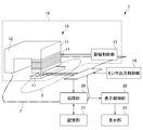
- the nondestructive inspection apparatus 1 includes a magnetic flux generation unit 16, an induced electromotive force detection unit 17 (magnetic flux detection element), a sensor output switching unit 18, a sensor output control unit 19, and a processing unit 20. (Detection processing unit) and a storage unit 21.
- the magnetic flux generation unit 16 includes a magnetic core 13 composed of the excitation magnetic pole 11 and the recovery magnetic pole 12, an excitation coil 14 that excites the magnetic core 13, and an excitation control unit 15 that controls the energization state and the interruption state of the excitation coil 14. .
- the shape of the magnetic core 13 will be described.
- the magnetic core 13 is formed in a substantially U-shape in which an excitation magnetic pole 11 is formed on one end side and a recovery magnetic pole 12 is formed on the other end side.
- coils C1 to Cn (n is a natural number of 2 or more) formed on the end face of the excitation magnetic pole 11 detect a change in magnetic flux generated at the welding site 3.
- the shape of the magnetic core 13 is not restricted to what was mentioned above.
- the magnetic flux generator 16 controls the excitation coil 14 to be energized by the excitation controller 15 to generate a magnetic flux between the excitation magnetic pole 11 and the recovery magnetic pole 12 and applies a magnetic field to the welded part 3.
- the exciting coil 14 a conductor is closely wound around a predetermined part of the magnetic core 13 in a spiral shape, and is configured by a solenoid coil.
- the direction in which the excitation coil 14 is wound will be described as the excitation magnetic pole 11. However, depending on the direction of the current flowing through the excitation coil 14, the direction in which the excitation coil 14 is wound becomes the excitation magnetic pole. Since it becomes a recovery magnetic pole, the direction around which the exciting coil 14 is wound may be used as the recovery magnetic pole.
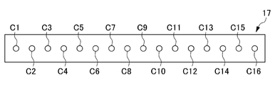
- the induced electromotive force detection unit 17 is disposed on the end face of the excitation magnetic pole 11 and detects a change in magnetic flux generated at the welding site 3. Moreover, the induced electromotive force detection part 17 is comprised by the array coil by which the some coil C is arrange
- the induced electromotive force detection unit 17 has a plurality of minute coils arranged in line symmetry.
- the induced electromotive force detection unit 17 shows a state in which 16 (C1 to C16) microcoils are evenly arranged. Specifically, coil C1 and coil C16, coil C2 and coil C15, coil C3 and coil C14, coil C4 and coil C13, coil C5 and coil C12, coil C6 and coil C11, coil C7 and coil C10, coil C8 and The coils C9 are equally arranged so as to be line symmetric.
- this embodiment demonstrates as what is comprised by 16 micro coils per row, it is not restricted to this, You may be comprised by multiple rows.
- weld marks can be visually recognized on the surface.
- a magnetic field is applied to the surface of the welding dent to generate a magnetic flux density, and the inside of the welding state is inspected by the coils C1 to C16.
- the sensor output control unit 19 sequentially selects outputs from the plurality of coils C1 to C16 included in the array coil.
- the sensor output switching unit 18 outputs a signal from the coil C selected by the sensor output control unit 19 to the processing unit 20.
- the processing unit 20 calculates the decay time constant ⁇ 1 of magnetic energy and the decay time constant ⁇ 2 of eddy current loss based on the signal supplied from the sensor output switching unit 18. Although details will be described later, by measuring the distribution of the decay time constant ⁇ 1 of the magnetic energy of the nugget portion and analyzing this, the shape and dimensions of the portion where the compositional change in the metal like the nugget portion is generated can be obtained. Can be sought.
- the processing unit 20 performs the first measurement of the induced electromotive force detection unit 17 at the first position of the DUT 2, performs the second measurement at the second position, and detects the internal detected at least by the first measurement. Based on the structure and the internal structure detected by the second measurement, the center position and / or the diameter of the nugget part formed inside the DUT 2 is estimated.
- the processing unit 20 performs the first measurement of the induced electromotive force detection unit 17 at a predetermined position of the object to be measured 2 (for example, the welded part 3 or its periphery visible from the outside), and then induces the induction.
- the second measurement is performed at a position where the electromotive force detection unit 17 is rotated by a predetermined angle (for example, 90 degrees) from the predetermined position of the DUT 2, and the internal structure detected by the first measurement and the second measurement are detected. Based on the internal structure, the center position of the nugget portion formed inside the DUT 2 and the diameter of the nugget portion are estimated.
- the center position of the nugget part formed in the DUT 2 and the nugget part The principle for estimating the diameter will be described. In the following description, the nugget portion is assumed to be circular.
- the center (for example, between the coils C8 and C9 in FIG. 2) of the detection (sensor) surface of the induced electromotive force detection unit 17 is perpendicular to the center of the nugget.
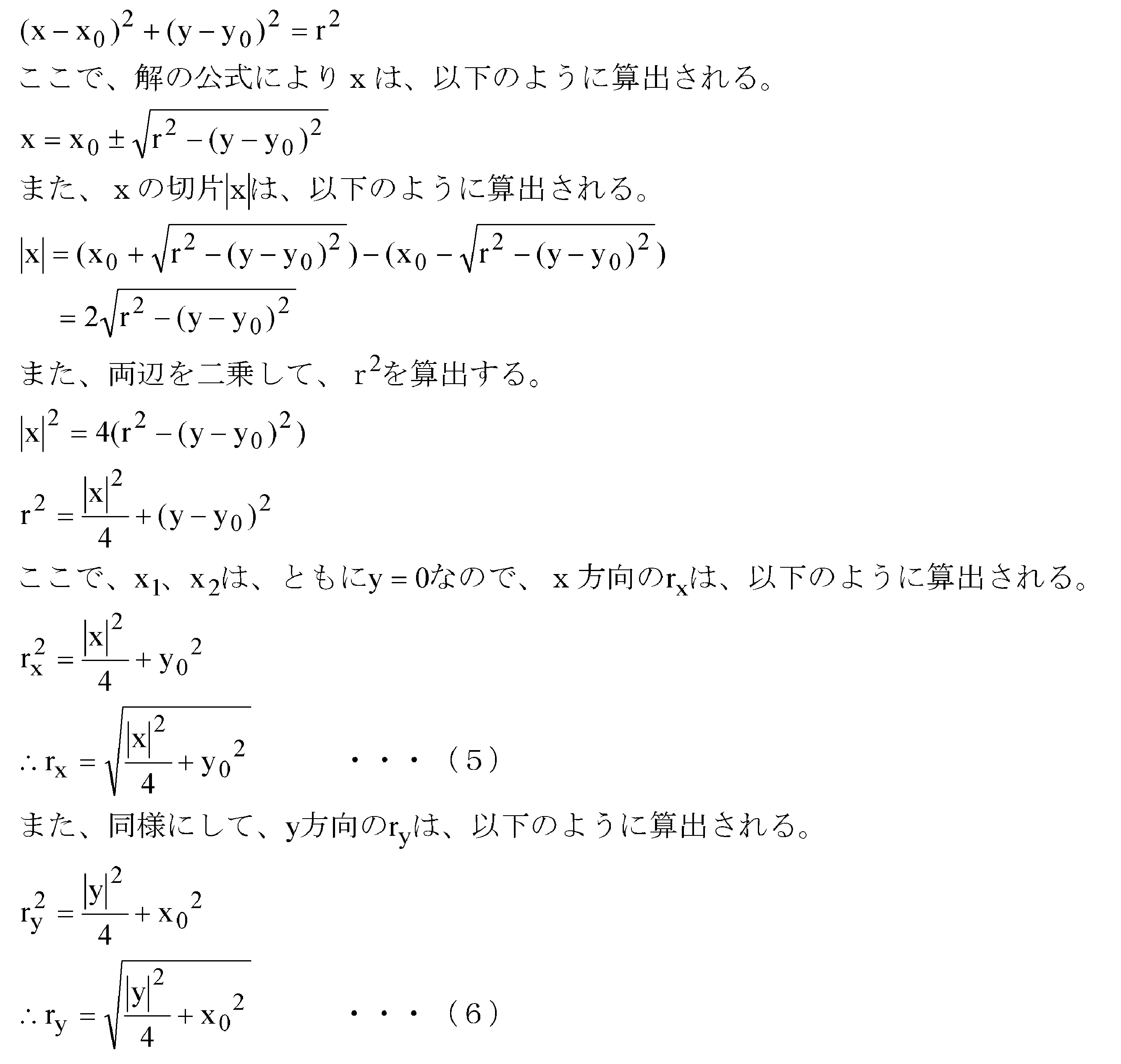
- the diameter of the nugget portion can be calculated based on the internal structure (FIG. 3). See). Further, assuming that the nugget portion has a circular shape, the radius r is the same in the x direction and the y direction.
- the center (for example, between the coils C8 and C9 in FIG. 2) of the detection (sensor) surface of the induced electromotive force detection unit 17 is perpendicular to the center of the nugget.
- the center coordinates (x 0 , y 0 ) of the nugget portion are calculated by the following expressions (1) and (2).
- the diameters in the x direction and the y direction are calculated by the following equations (3) and (4), respectively.
- the size of the nugget portion in the x direction is calculated as follows.
- the processing unit 20 calculates the radius r 2 of the nugget unit by substituting r x and r y into the following equation (7) and calculating the average value in the x direction and the y direction.
- the processing unit 20 detects x 1 and x 2 based on the detection value detected from the induced electromotive force detection unit 17 and substitutes it into the equation (1) to calculate x 0 . And the diameter in the x direction is calculated by substituting it into the equation (3).
- the processing unit 20 detects y 1 and y 2 based on the detection value detected from the induced electromotive force detection unit 17 and substitutes it into the equation (2) to calculate y 0 .
- the diameter in the y direction is calculated by substituting it into the equation (4).
- the processing unit 20 calculates r x by substituting the x-direction diameter and y 0 into the equation (5), and also substitutes the y-direction diameter and x 0 into the equation (6) and r y. Is calculated. Then, the processing unit 20, by substituting r x and r y in (7), to calculate the diameter r 2 of the nugget.
- the nondestructive inspection apparatus 1 has a cross-shaped detection (sensor) surface of the induced electromotive force detection unit 17 as shown in FIG.
- the nondestructive inspection apparatus 1 measures the center position of the nugget portion and the diameter of the nugget portion based on the deviation from the center portion of the nugget portion (c in FIG. 4) by measuring the same position different by 90 degrees. be able to. Further, as shown in FIG.
- the nondestructive inspection apparatus 1 performs the first measurement (measurement in the x-axis direction) when the detection surface of the induced electromotive force detection unit 17 is deviated from the center portion of the nugget portion.
- the result is a waveform as indicated by d in FIG. 4
- the result of the second measurement is a waveform as indicated by e in FIG.
- the induced electromotive force detection unit 17 may be configured by arranging a plurality of minute coils in a row. When configured in this way, the processing unit 20 arranges the induced electromotive force detection unit 17 at a predetermined position of the DUT 2 to perform the first measurement, and then the induced electromotive force detection unit 17. Is placed at a position rotated by a predetermined angle (for example, 90 degrees) from a predetermined position of the DUT 2, and the second measurement is performed.
- a predetermined angle for example, 90 degrees
- the sensor probe 5 including the magnetic core 13, the excitation coil 14, and the induced electromotive force detection unit 17 is attached to the robot arm 101 (arm unit), and moved on the object 2 to be measured.
- a method for estimating the center position of the part and the diameter of the nugget part will be described.
- the robot arm 101 is connected to a control device (drive control unit) (not shown) and can freely move on the DUT 2 under the control of the control device.
- the tip of the robot arm 101 is configured to be able to rotate in the plane direction according to the control of the control device.
- the sensor probe 5 is placed by the robot arm 101 at a predetermined position on the object to be measured 2 (for example, welding dent B in FIG. 5).
- the sensor probe 5 may be in contact with the device under test 2 or may be disposed at a predetermined height from the device under test 2.
- the sensor probe 5 performs a first measurement to inspect the internal structure at a predetermined position.
- the robot arm 101 rotates the tip portion by a predetermined angle (for example, 90 degrees) in the plane direction.
- a predetermined angle for example, 90 degrees
- the sensor probe 5 performs a second measurement to inspect the internal structure at a position rotated by a predetermined angle.
- the processing unit 20 Based on the internal structure detected by the first measurement and the internal structure detected by the second measurement, the processing unit 20 has the center position of the nugget part formed inside the device under test 2 and the diameter of the nugget part. Is calculated.
- the induced electromotive force detection unit 17 may be configured by arranging a plurality of minute coils in a cross shape in one vertical row and one horizontal row.
- the processing unit 20 arranges the induced electromotive force detection unit 17 at a predetermined position of the DUT 2, and the induced electromotive force detection unit 17 arranged in a vertical row or a horizontal row. Then, the first measurement is performed, and then the second measurement is performed by the induced electromotive force detection unit 17 arranged in one horizontal row or one vertical row.
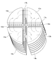
- a first detection unit 17a and a second detection unit 17b in which a plurality of coils are equally arranged are configured in a cross shape.
- the magnetic core 13 is composed of small magnetic cores 13a, 13b, 13c, and 13b.
- the small magnetic cores 13a, 13b, 13c, and 13d are each wound around a predetermined direction by exciting coils 14a, 14b, 14c, and 14d. Further, as shown in FIG. 6, the small magnetic cores 13a, 13b, 13c, and 13d are arranged in the respective regions of the induced electromotive force detection unit 17 configured in a cross shape.
- the small magnetic core 13c functions as a recovery magnetic pole, and thus the excitation coil 14c may not be wound.
- the sensor probe 5 is arranged at a predetermined position (for example, welding dent) on the workpiece 2 by the robot arm 101.
- the sensor probe 5 may be in contact with the device under test 2 or may be disposed at a predetermined height from the device under test 2.
- Sensor probe 5 performs a first measurement to inspect the internal structure at a predetermined position. For example, in the first measurement, the sensor probe 5 generates a magnetic flux between the small magnetic core 13a and the small magnetic core 13d, and between the small magnetic core 13b and the small magnetic core 13c, and applies a magnetic field to the welded portion 3 to obtain a predetermined value. After the elapse of time, the magnetic flux is interrupted, and a change in the magnetic flux generated in the welded part 3 is detected by the first detection unit 17a.
- the sensor probe 5 performs the second measurement to inspect the internal structure at the same position.
- the sensor probe 5 generates a magnetic flux between the small magnetic core 13a and the small magnetic core 13b, and between the small magnetic core 13d and the small magnetic core 13c, and applies a magnetic field to the welded portion 3 so as to be predetermined.
- the magnetic flux is interrupted, and the change of the magnetic flux generated in the welded part 3 is detected by the second detection unit 17b.
- the processing unit 20 Based on the internal structure detected by the first measurement and the internal structure detected by the second measurement, the processing unit 20 has the center position of the nugget part formed inside the device under test 2 and the diameter of the nugget part. Is calculated.
- the magnetic resistance Rm L / S ⁇ ⁇ .
- the magnetic resistance of the magnetic flux passing through each coil can be estimated by integrating the change in magnetic flux density generated in all the coils C1 to C16 and obtaining the intercept and time constant of the curve represented by the exponential function. .
- the magnetic resistance of each coil is obtained, smoothed, and displayed on a display, the internal structure of the device under test 2 can be schematically visualized.
- Factors affecting the magnetic resistance can be roughly divided into three (shape (air layer), residual stress, and hardness).
- shape air layer
- residual stress residual stress
- hardness the magnetic flux generated by the excitation coil 14 passes through the gap via the induced electromotive force detection unit 17 and enters the inside of the DUT 2 (work). Thereafter, the magnetic flux is affected by residual stress and hardness inside the workpiece.
- the nondestructive inspection apparatus 1 generates a magnetic field twice with respect to the workpiece by the exciting coil 14 as shown in FIG. Specifically, the exciting coil 14 applies a magnetic field for a short time as the first magnetic field, and generates a magnetic flux density by applying a shallow magnetic field to the workpiece by the skin effect (B1 in FIG. 7). Further, the exciting coil 14 applies a magnetic field for a sufficiently long time as the second magnetic field, and generates a magnetic flux density by applying a magnetic field deeply to the nugget portion (B2 in FIG. 7). ).
- the processing unit 20 shallowly applies a magnetic field to generate a magnetic flux density (magnetic resistance R 0 ) and a measurement result obtained by applying a deep magnetic field to generate a magnetic flux density ( The differential magnetic resistance R of the magnetic resistance R 2 ) is obtained.
- R 0 R f + R a + R w0
- the R f shows a magnetic resistor having a magnetic core 13 from the induced electromotive force detecting portion 17 of configured sensor itself
- R a shows a magnetic resistance exists between the workpiece and the sensor.
- R w0 represents the magnetic resistance of the workpiece surface
- R w represents the magnetic resistance of the workpiece interior.
- the nondestructive inspection apparatus 1 can obtain the magnetic resistance R with high accuracy regardless of the surface shape of the workpiece by obtaining the differential magnetic resistance R from the two-stage measurement results.
- the nondestructive inspection apparatus 1 first measures the magnetic resistance R 0 by applying a shallow magnetic field to generate a magnetic flux density, and then applying a magnetic field deeply to generate the magnetic flux density to thereby generate the magnetic resistance.
- R 2 is measured, the present invention is not limited to this, but the magnetoresistance R 2 is measured by first applying a magnetic field deeply to generate a magnetic flux density, and then generating a magnetic flux density by applying a shallow magnetic field to thereby generate the magnetic resistance.
- R 0 may be measured.
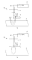
- FIG. 8A shows a schematic state when a magnetic field is applied to generate a magnetic flux density.
- the device under test 2 generates a magnetic flux density by applying a magnetic field to the magnetic flux passing portion according to the strength of the magnetic field.
- the magnetic flux loop is separated into a closed loop around the exciting coil 14 and a closed loop around the DUT 2 (FIG. 8 ( see b)).
- the closed loop of magnetic flux around the exciting coil 14 rapidly decreases and disappears.
- the closed loop of the magnetic flux around the object to be measured 2 does not disappear immediately (residual magnetism) but is held in the magnetic material as magnetic energy, gradually disappears, and finally returns to the state before applying the static magnetic field. .
- the nondestructive inspection apparatus 1 detects changes of the magnetic flux of the DUT 2 with respect to time using the coils C1 to C16. Although the change in the magnetic flux detected by the coils C1 to C16 after the static magnetic field is cut off is ideally monotonously decreased in an exponential function, it actually decreases, and thus decreases in a predetermined curve.
- FIG. 9 shows the disappearance process of the remanent magnetism.
- This magnetic energy loss process as shown in FIG. 9 (a), the magnetic flux density passing through any one of the coils C1 to C16 and phi 1.
- eddy currents induced by changes in the magnetic flux density ⁇ 1 are In 1 , In 2 , In 3 ...
- their induction coefficients are M 1 , M 2 , M 3 . It is considered that the eddy currents In 1 , In 2 , In 3 ... Induced from the change of the magnetic flux density ⁇ 1 are independent.
- FIG. 9B shows an equivalent circuit of FIG.
- R 2 represents the electrical resistance of the eddy current i 2
- L 2 represents the inductance of the eddy current i 2 .
- FIG. 10 is obtained by replacing the closed loop of the magnetic flux density ⁇ with a magnetic equivalent circuit.
- i 1 indicates the magnetic flux density
- R 1 indicates the difficulty of returning the magnetic flux at the measurement site holding the magnetic flux (resistance)
- L 1 is the inductance of the magnetic flux space holding the magnetic flux.
- I 2 indicates the eddy current at the measurement site
- R 2 indicates the electric resistance of the eddy current loop
- L 2 indicates the volume of the space in which the eddy current is generated.
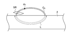
- the magnetic energy W can be expressed by equation (8). Note that L in FIG. 11 indicates the length of magnetic flux density generated by applying a magnetic field.
- L is a value proportional to the volume of the space holding the magnetic flux (that is, the space holding the magnetic energy).
- equation (8) is the same as the energy stored when the current i 1 is passed through the coil having the inductance L. From these, the inductance L 1 of FIG. 10, it can be seen that correspond to the volume of the whole space that holds the magnetic flux.
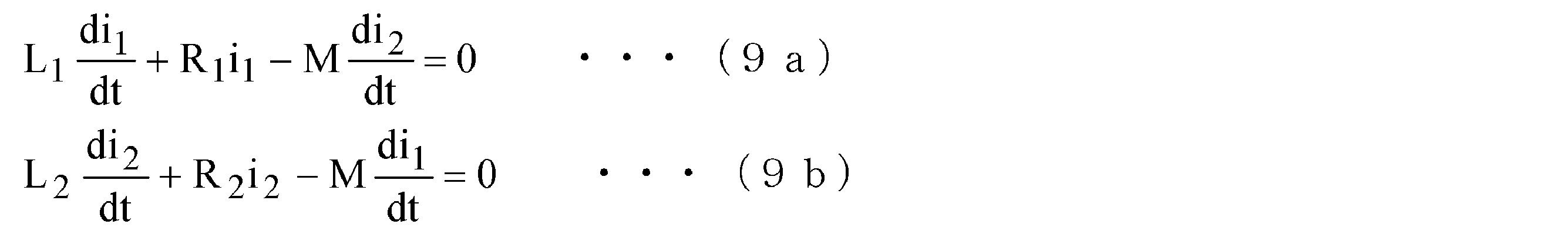
- equations (9a) and (9b) are obtained.
- the induction coefficient M is small and the eddy current i 2 induced from the change of the magnetic flux density i 1 is small, that is, when L1 ⁇ L2 >> M ⁇ M, the following results are obtained.
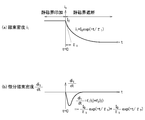
- FIG. 12A shows a transient change of the magnetic flux density i 1 given by the equation (12).
- the second term on the right side of the equation (12) can be ignored, and can be approximated only by the first term.
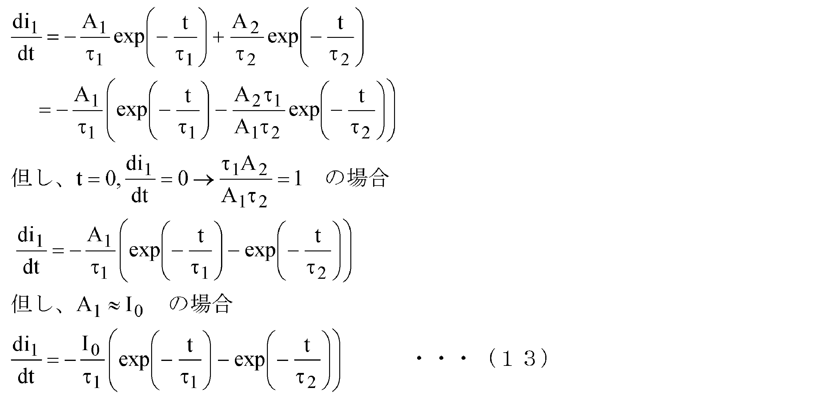
- the voltage measured by a loop coil generally used as a magnetic sensor is a value proportional to the rate of change of magnetic flux density, that is, the differential magnetic flux density. Therefore, the expression (12) is differentiated with respect to time t to obtain the expression of the differential magnetic flux density shown in the expression (13).
- FIG.12 (b) shows the transient change of the differential magnetic flux density given by (13) Formula.
- the expression (12) is an expression indicating a change in the magnetic flux density i 1 obtained by the coils C1 to C16
- the expression (13) is an expression indicating a change in the differential magnetic flux density (di 1 / dt).
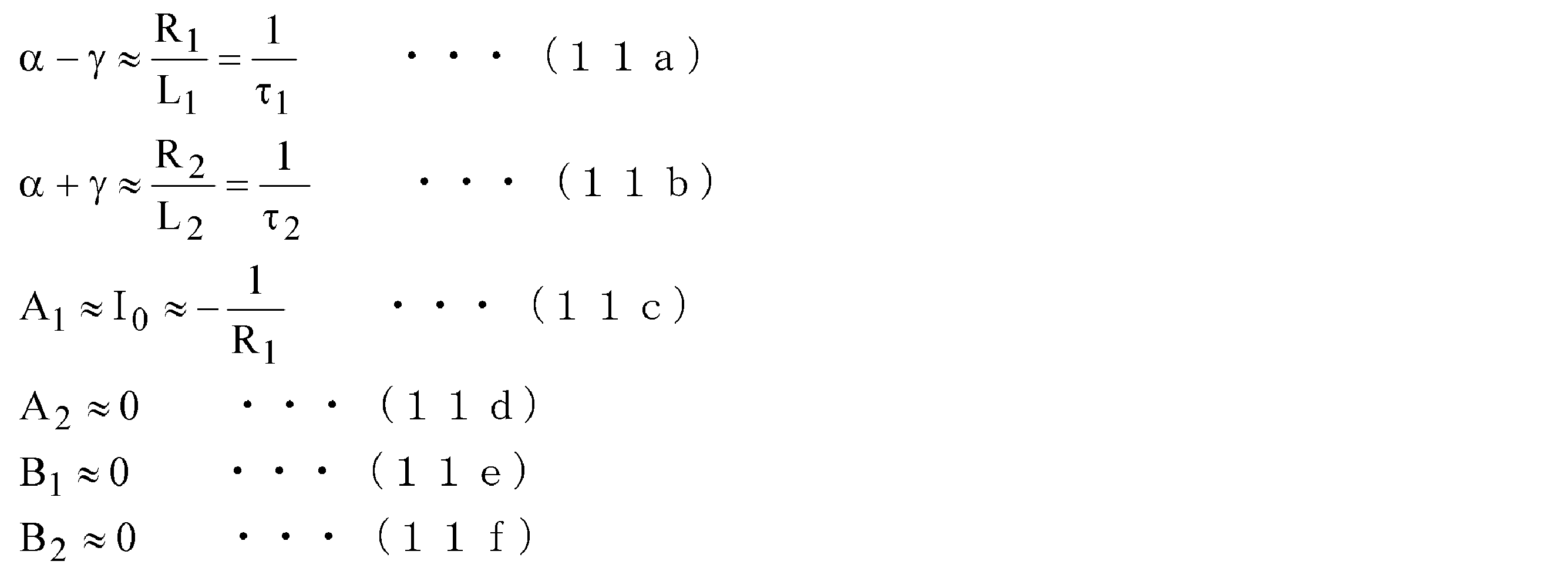
- the time constant ⁇ 1 of the first term on the right side of the equation (13) is equal to “L1 / R1” as given by the equation (11a).
- the first term on the right side of the equation (13) is a term indicating a magnetic flux density reduction characteristic in the vicinity of the DUT 2 after the static magnetic field is interrupted, that is, a magnetic energy attenuation characteristic.
- the nugget part (where the metal composition or structural strength changes) and the parts other than the nugget part (where the metal composition or structural strength does not change) A change occurs in the time constant ⁇ 1 . Therefore, if the distribution of the time constant ⁇ 1 in the spot welded portion is measured and analyzed, the shape / dimension of the portion such as the nugget portion in which the compositional change of the metal occurs can be obtained.
- the time constant ⁇ 2 of the second term on the right side of the equation (13) is equal to “L 2 / R 2 ” as given by the equation (11b). Therefore, this term corresponds to the time constant of the equivalent circuit of the eddy current i 2 shown in FIG. That is, the second term on the right side of equation (13) is a term indicating the attenuation characteristics of eddy current loss. As shown in FIG. 11, the length of the magnetic flux density in the measuring object 2 L, when the magnetic flux passing area and ds, it is possible to indicate the L 2 (14) in expression.
- the time constant ⁇ 2 of the attenuation characteristic of the eddy current loss passes through the magnetic path where the eddy current is generated, that is, the steel plate, as shown in the equation (15). It is proportional to the length of the magnetic path.
- the nondestructive inspection apparatus 1 has a time constant when a magnetic field is generated by applying a shallow magnetic field and a time constant when a magnetic field is generated by applying a deep magnetic field as shown in the measurement principle described above. Based on the magnetic resistance Rf of the sensor itself and the time constant of canceling the magnetic resistance Ra existing between the workpiece and the sensor, the time constant of the coil detecting the air layer is calculated with the line-symmetric position. Therefore, even if a part of the coil detects an air layer, it does not affect the detection results of other coils, and inspection can be carried out smoothly without obstructing the inspection work. It can be carried out.
- the nondestructive inspection apparatus 1 may have a configuration other than the above-described embodiment.
- the nondestructive inspection apparatus 1 allows the recovery magnetic poles 12a and 12b arranged on the left and right to recover the magnetic field generated from one excitation magnetic pole 11 without waste, so that the nugget portion in the magnetosphere range can be measured.
- a configuration in which one induced electromotive force detector 17c and second induced electromotive force detector 17d are arranged in parallel is proposed as another embodiment.
- the nondestructive inspection apparatus 1 uses two of the first induced electromotive force detection unit 17c and the second induced electromotive force detection unit 17d, so that one induced electromotive force detection is performed. Compared with the apparatus constituted by the unit, it is possible to realize double measurement accuracy and improve the ease of measurement.
- the nondestructive inspection apparatus 1 can obtain a planar (two-dimensional) or three-dimensional (three-dimensional) measurement result instead of linear (one-dimensional), and can measure more multi-dimensional nuggets. is there. Further, the nondestructive inspection apparatus 1 has the following merits. Since the measurement method (measurement is performed by bringing the sensor probe 5 close to or in contact with the welding dent) is easy, learning is easy. -It is not necessary to rotate the sensor probe 5 at the time of measurement. ⁇ Circuit such as switching is unnecessary. ⁇ The nugget diameter can be estimated with a single measurement. ⁇ Resolution is improved. ⁇ Improves the directivity of magnetic field lines
- the processing unit 20 applies a magnetic field to the object to be measured 2 to generate a magnetic flux density, detects the magnetic flux emitted from a plurality of positions of the object to be measured 2 after blocking the magnetic field, and detects an induced electromotive force.
- the time constant of the transient change of a some magnetic flux is calculated by the part 17, and the internal structure of the said to-be-measured object 2 is detected from the distribution state of the said time constant.
- the processing unit 20 is provided with recovery poles 12 in parallel on both sides in the longitudinal direction of the excitation magnetic pole 11 (excitation part), and a plurality of guides are provided below the excitation magnetic pole 11 and corresponding to the recovery magnetic poles 12.
- An electromotive force detection unit 17 is arranged, and magnetic flux emitted from a plurality of positions of the device under test 2 is measured by a plurality of induced electromotive force detection units 17 and formed inside the device under test 2 based on the measurement result. The center position and / or the diameter of the nugget portion is estimated.
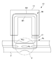
- FIG. 13A shows an external view when the magnetic core 13 is viewed from the front direction
- FIG. 13B shows an external view when the magnetic core 13 is viewed from the bottom surface direction.
- the magnetic core 13 is configured by forming the recovery magnetic poles 12 a and 12 b in a U shape, and disposing the excitation magnetic pole 11 in a space portion formed in the U shape.
- the induced electromotive force detection unit 17 is disposed below the excitation magnetic pole 11 so as to correspond to the recovery magnetic poles 12a and 12b.
- the induced electromotive force detection unit 17 has a plurality of minute coils arranged in line symmetry.
- the induced electromotive force detector 17 includes a first induced electromotive force detector 17c and a second induced electromotive force detector 17d.
- the first induced electromotive force detection unit 17c is disposed below the excitation magnetic pole 11 and in parallel with the one recovery magnetic pole 12a.
- the second induced electromotive force detector 17d is disposed below the excitation magnetic pole 11 and in parallel with the other recovery magnetic pole 12b.
- the processing unit 20 acquires the measurement results of the first induced electromotive force detection unit 17c and the second induced electromotive force detection unit 17d. Specifically, the processing unit 20 analyzes the distribution of the decay time constant of each magnetic energy from the detection results of the first induced electromotive force detection unit 17c and the second induced electromotive force detection unit 17d, and FIG. As shown in (a), a line segment a and a line segment b are calculated. In addition, the length of the line segment a is calculated according to the number of the coils which detected the nugget part among the several coils which comprise the 1st induced electromotive force detection part 17c. Similarly, the length of the line segment b is calculated according to the number of coils that have detected the nugget portion among the plurality of coils that constitute the second induced electromotive force detection portion 17d.
- the processing unit 20 extracts three points farthest from the measurement result and forms a triangle.
- a triangle is formed from the start point or end point of the line segment a and the start point and end point of the line segment b.
- the processing unit 20 forms a circumscribed circle c that passes through three points from the intersection of the perpendicular bisectors calculated by the respective triangles of the perpendicular bisectors of the two sides forming the triangle.
- the processing unit 20 calculates the center position d and the diameter e of the circumscribed circle c, thereby estimating the center position and / or the diameter of the nugget part formed inside the DUT 2. To do.
- the nondestructive inspection apparatus 1 can virtually draw the estimated nugget part and display it on the display part 23.
- the display control unit 22 estimates the center position of the nugget part and / or the diameter of the nugget part formed inside the DUT 2, based on the center position and / or diameter of the nugget part, A virtual image of the nugget part is generated and displayed on the display part 23.
- the processing unit 20 scans the sensor probe 5 including the magnetic core 13 on the object 2 to be measured, and the plurality of locations (FIG. 15).
- the processing unit 20 scans the sensor probe 5 including the magnetic core 13 on the object 2 to be measured, and the plurality of locations (FIG. 15).
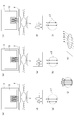
- FIGS. 15A, 15B, and 15C the processing unit 20 scans the sensor probe 5 including the magnetic core 13 on the object 2 to be measured, and the plurality of locations (FIG. 15).
- FIGS. 15A, 15B, and 15C the processing unit 20 scans the sensor probe 5 including the magnetic core 13 on the object 2 to be measured, and the plurality of locations (FIG. 15).
- FIG. 15A shows an external view when the sensor probe 5 is brought close to the position closer to the left from the center position of the welding dent (first measurement).
- FIG. 15B shows an external view when the sensor probe 5 is brought close to the center position of the welding dent and measured (second measurement).
- FIG. 15C shows an external view when measurement is performed with the sensor probe 5 being brought close to a position closer to the right from the center position of the welding dent (third measurement).
- the processing unit 20 analyzes the distribution of the decay time constant of the magnetic energy obtained from the first induced electromotive force detection unit 17c and the second induced electromotive force detection unit 17d by the first measurement, and generates a magnetic waveform. Is calculated (FIG. 15D).
- the processing unit 20 calculates a line segment a and a line segment b from the calculated magnetic waveform. The lengths of the line segment a and the line segment b depend on the number of coils that have detected the nugget part among the plurality of coils constituting the first induced electromotive force detection unit 17c and the second induced electromotive force detection unit 17d. Is calculated. Further, as shown in FIG. 15G, the processing unit 20 calculates a circle c1 where the start point and the end point of the line segment a and the line segment b intersect, and estimates this as the diameter of the nugget part.
- the processing unit 20 analyzes the distribution of the decay time constant of the magnetic energy obtained from the first induced electromotive force detection unit 17c and the second induced electromotive force detection unit 17d by the second measurement, and generates a magnetic waveform. Is calculated (FIG. 15E).
- the processing unit 20 calculates a line segment c and a line segment d from the calculated magnetic waveform. The lengths of the line segment c and the line segment d depend on the number of coils that have detected the nugget part among the plurality of coils constituting the first induced electromotive force detection unit 17c and the second induced electromotive force detection unit 17d. Is calculated. Further, as shown in FIG. 15 (h), the processing unit 20 calculates a circle c2 where the start point and the end point of the line segment c and the line segment d intersect, and estimates this as the diameter of the nugget portion.
- the processing unit 20 analyzes the distribution of the decay time constant of the magnetic energy obtained from the first induced electromotive force detection unit 17c and the second induced electromotive force detection unit 17d by the third measurement, and generates a magnetic waveform. Is calculated (FIG. 15 (f)).
- the processing unit 20 calculates a line segment e and a line segment f from the calculated magnetic waveform. The lengths of the line segment e and the line segment f depend on the number of coils that have detected the nugget part among the plurality of coils constituting the first induced electromotive force detection unit 17c and the second induced electromotive force detection unit 17d. Is calculated. Further, as shown in FIG. 15 (i), the processing unit 20 calculates a circle c3 in which the start point and the end point of the line segment e and the line segment f intersect, and estimates this as the diameter of the nugget part.
- the display control unit 22 generates a planar image based on the circles c1 to c3 calculated by the processing unit 20, and displays it on the display unit 23 as a virtual image (planar) of the nugget unit (FIG. 15 (j)). .
- the line segment b and the line segment e are displayed in an overlapping manner because the same part is measured.
- the display control unit 22 generates a three-dimensional image based on the circles c1 to c3 calculated by the processing unit 20, and displays it as a virtual image (three-dimensional) of the nugget unit on the display unit 23 (FIG. 15 (k). )).
- the line segment b and the line segment e are displayed in an overlapping manner because the same part is measured.
- the display control unit 22 calculates the height of the nugget portion based on the height of the magnetic waveform calculated by the first measurement, the second measurement, and the third measurement.
- the nondestructive inspection apparatus 1 displays a virtual image of the nugget part planarly or three-dimensionally on the display unit 23 based on the results measured at a plurality of positions.
- the size can be grasped visually, and the inspection accuracy can be improved.
Landscapes
- General Physics & Mathematics (AREA)
- Physics & Mathematics (AREA)
- Chemical & Material Sciences (AREA)
- Immunology (AREA)
- Health & Medical Sciences (AREA)
- Life Sciences & Earth Sciences (AREA)
- Chemical Kinetics & Catalysis (AREA)
- General Health & Medical Sciences (AREA)
- Analytical Chemistry (AREA)
- Electrochemistry (AREA)
- Biochemistry (AREA)
- Pathology (AREA)
- Engineering & Computer Science (AREA)
- Mechanical Engineering (AREA)
- Investigating Or Analyzing Materials By The Use Of Magnetic Means (AREA)
Abstract
Description
また、予め、誘導起電力検出部17のコイルC間の距離は分かっているので、内部構造に基づいて、ナゲット部の径(本実施例では、半径r)を算出することができる(図3を参照)。また、ナゲット部は、円形状であると仮定すると、半径rは、x方向及びy方向において同じとなる。
x0=(x1+x2)/2・・・(1)
y0=(y1+y2)/2・・・(2)


誘導起電力検出部17は、複数の微小コイルが一列に配置されて構成されていても良い。このように構成される場合には、処理部20は、誘導起電力検出部17を被測定物2の所定の位置に配置して、第一の測定を行い、その後、誘導起電力検出部17を被測定物2の所定の位置から所定角度(例えば、90度)回転させた位置に配置して、第二の測定を行う。
そして、第一の測定が終わった場合に、ロボットアーム101は、先端部を平面方向に所定角度(例えば、90度)回転する。
つぎに、センサプローブ5は、所定角度回転した位置における内部構造を検査するために第二の測定を行う。
つぎに、誘導起電力検出部17は、複数の微小コイルが縦一列及び横一列に十字形状に配置されて構成されていても良い。このように構成される場合には、処理部20は、誘導起電力検出部17を被測定物2の所定の位置に配置して、縦一列又は横一列に配置された誘導起電力検出部17により第一の測定を行い、その後、横一列又は縦一列に配置された誘導起電力検出部17により第二の測定を行う。
誘導起電力検出部17は、図6に示すように、複数のコイルが均等に配置される第1検出部17aと第2検出部17bが十字形状に構成されている。
センサプローブ5は、ロボットアーム101によって被測定物2上の所定の位置(例えば、溶接打痕)に配置される。なお、センサプローブ5は、被測定物2に接触しても良いし、被測定物2から所定の高さのところに配置されても良い。
つぎに、非破壊検査装置1による測定原理について説明する。磁束は、磁気を発生するための励磁コイル14(励磁磁極11)から出て、励磁コイル14直下に配置された誘導起電力検出部17を通り抜け、被測定物2(ワーク)内に入り、ナゲット部を通り抜け、回収磁極12を通って、元の励磁コイル14(励磁磁極11)に戻ってくる。
図7に示すように、励磁コイル14により発生した磁束は、誘導起電力検出部17を介して空隙を通り抜けて被測定物2(ワーク)の内部に入る。その後、磁束は、ワーク内部において残留応力及び硬度の影響を受けることになる。
ここで、非破壊検査装置1は、図7に示すように、励磁コイル14によりワークに対して、磁界を2度発生させる。具体的には、励磁コイル14は、1度目の磁界として、短時間の磁界印加であって、表皮効果によってワークを浅く磁界を加えて磁束密度を発生させる(図7中のB1)。また、励磁コイル14は、2度目の磁界として、十分に長い時間の磁界印加であって、ナゲット部まで到達するくらいまで、ワークを深く磁界を加えて磁束密度を発生させる(図7中のB2)。
R0=Rf+Ra+Rw0
R2=Rf+Ra+Rw
R=R2-R0=Rw-Rw0
なお、Rfは、磁心13と誘導起電力検出部17から構成されるセンサ自体の持つ磁気抵抗を示し、Raは、ワークとセンサ間に存在する磁気抵抗を示している。また、Rw0は、ワーク表面の磁気抵抗を示し、Rwは、ワーク内部の磁気抵抗を示している。
つぎに、処理部20によって磁気エネルギーの減衰時定数τ1と、渦電流損失の減衰時定数τ2を算出する具体的な方法について説明する。非破壊検査装置1のコイルC1乃至C16は、被測定物2の検査対象となる部位の上面に配置される。そして、非破壊検査装置1は、励磁コイル14を通電状態にし、励磁磁極11と回収磁極12との間に発生した磁束により被測定物2に対して磁界を加えて磁束密度を発生させる。ここで、磁界を加えて磁束密度を発生させたときの模式的な様子を図8(a)に示す。被測定物2は、図8(a)に示すように、磁界の強さに応じて磁束通過部分が磁界が加えられて磁束密度が発生する。


また、非破壊検査装置1は、上述した実施例以外の構成でも良い。
非破壊検査装置1は、1つの励磁磁極11から発生させた磁界を無駄なく左右に配置されている回収磁極12a、12bに回収させることにより、磁気圏範囲内にあるナゲット部を測定できるように第1の誘導起電力検出部17c及び第2の誘導起電力検出部17dを並列配置にした構成を他の実施例として提案する。
また、非破壊検査装置1は、他に以下のようなメリットがある。
・測定方法(センサプローブ5を溶接打痕に近接又は接触させて測定する)が簡易なので、習熟が容易である。
・測定時に、センサプローブ5を回転させなくて良い。
・スイッチング等の回路が不要である。
・一回の測定でナゲット径が推定できる。
・解像度が向上する。
・磁力線の指向性を向上できる
処理部20は、上述したように、被測定物2に磁場を印加して磁束密度を発生させ、当該磁場を遮断後に、当該被測定物2の複数位置から放出される磁束を誘導起電力検出部17により測定し、複数の磁束の過渡変化の時定数を算出し、当該時定数の分布状態から当該被測定物2の内部構造を検出する。
第1の誘導起電力検出部17cは、励磁磁極11の下方であって、一方の回収磁極12aに平行に配置されている。
第2の誘導起電力検出部17dは、励磁磁極11の下方であって、他方の回収磁極12bに平行に配置されている。
処理部20は、当該三角形を形成する二つの辺の垂直二等分線をそれぞれの三角形にて算出した垂直二等分線の交点から、3点を通る外接円cを形成する。
2 被測定物
5 センサプローブ
11 励磁磁極
12 回収磁極
13 磁心
14 励磁コイル
15 励磁制御部
16 磁束発生部
17 誘導起電力検出部(磁束検出素子)
18 センサ出力切替部
19 センサ出力制御部
20 処理部(検出処理部)
21 記憶部
22 表示制御部
23 表示部
Claims (8)
- 被測定物に磁場を印加して磁束密度を発生させ、当該磁場を遮断後に、当該被測定物の複数位置から放出される磁束を磁束検出素子により測定し、複数の磁束の過渡変化の時定数を算出し、当該時定数の分布状態から当該被測定物の内部構造を検出する検出処理部を有し、
前記検出処理部は、前記磁束検出素子を前記被測定物の第一の位置で第一の測定を行い、第二の位置で第二の測定を行い、少なくとも前記第一の測定により検出した内部構造と前記第二の測定により検出した内部構造に基づいて、前記被測定物の内部に形成されているナゲット部の中心位置及び/又は当該ナゲット部の径を推定する非破壊検査装置。 - 被測定物に磁場を印加して磁束密度を発生させ、当該磁場を遮断後に、当該被測定物の複数位置から放出される磁束を磁束検出素子により測定し、複数の磁束の過渡変化の時定数を算出し、当該時定数の分布状態から当該被測定物の内部構造を検出する検出処理部を有し、
前記検出処理部は、前記磁束検出素子を前記被測定物の所定の位置で第一の測定を行い、前記磁束検出素子を前記被測定物の前記所定の位置から所定角度回転した位置で第二の測定を行い、前記第一の測定により検出した内部構造と前記第二の測定により検出した内部構造に基づいて、前記被測定物の内部に形成されているナゲット部の中心位置及び/又は当該ナゲット部の径を推定する非破壊検査装置。 - 前記磁束検出素子は、複数の微小コイルが一列に配置されて構成されており、
前記検出処理部は、前記磁束検出素子を前記被測定物の所定の位置に配置して、前記第一の測定を行い、前記磁束検出素子を前記被測定物の前記所定の位置から所定角度回転させた位置に配置して、前記第二の測定を行う請求項2記載の非破壊検査装置。 - 前記磁束検出素子は、複数の微小コイルが縦一列及び横一列に十字形状に配置されて構成されており、
前記検出処理部は、前記磁束検出素子を前記被測定物の所定の位置に配置して、前記縦一列又は横一列に配置された前記磁束検出素子により前記第一の測定を行い、前記横一列又は縦一列に配置された前記磁束検出素子により前記第二の測定を行う請求項2記載の非破壊検査装置。 - 被測定物に磁場を印加して磁束密度を発生させ、当該磁場を遮断後に、当該被測定物の複数位置から放出される磁束を磁束検出素子により測定し、複数の磁束の過渡変化の時定数を算出し、当該時定数の分布状態から当該被測定物の内部構造を検出する検出処理部を有し、
前記検出処理部は、励磁部の長手方向において、その両側に平行に磁気回収部が設けられ、前記励磁部の下方であって前記磁気回収部に対応するように複数の磁束検出素子が配置され、前記被測定物の複数位置から放出される磁束を前記複数の磁束検出素子により測定し、当該測定の結果に基づいて、前記被測定物の内部に形成されているナゲット部の中心位置及び/又は当該ナゲット部の径を推定する非破壊検査装置。 - 前記磁束検出素子は、第1の磁束検出素子と第2の磁束検出素子から構成され、
前記第1の磁束検出素子は、前記励磁部の下方であって、一方の磁気回収部に平行に配置され、
前記第2の磁束検出素子は、前記励磁部の下方であって、他方の磁気回収部に平行に配置され、
前記検出処理部は、前記第1の磁束検出素子及び前記第2の磁束検出素子の測定結果を取得し、当該測定結果から最も離れている3点を抽出して三角形を形成し、当該三角形を形成する二つの辺の垂直二等分線をそれぞれの三角形にて算出した垂直二等分線の交点から、前記3点を通る外接円を形成し、当該外接円の中心位置と直径を算出することにより、前記被測定物の内部に形成されているナゲット部の中心位置及び/又は当該ナゲット部の径を推定する請求項5記載の非破壊検査装置。 - 前記磁束検出素子を有する測定装置を把持するアーム部と、
測定対象となる前記被測定物の所定の位置に前記磁束検出素子が配置されるように、前記アーム部を移動する駆動制御部を備える請求項1乃至6のいずれか一項に記載の非破壊検査装置。 - 表示部と、
前記表示部を制御する表示制御部を備え、
前記表示制御部は、前記被測定物の内部に形成されているナゲット部の中心位置及び/又は当該ナゲット部の径を推定した場合に、当該ナゲット部の中心位置及び/又は径に基づいて、当該ナゲット部の仮想的な画像を生成し、前記表示部に表示する請求項1乃至6のいずれか一項に記載の非破壊検査装置。
Priority Applications (6)
| Application Number | Priority Date | Filing Date | Title |
|---|---|---|---|
| MX2013011802A MX341497B (es) | 2011-04-12 | 2012-04-05 | Dispositivo de prueba no destructiva. |
| JP2013509868A JP5607822B2 (ja) | 2011-04-12 | 2012-04-05 | 非破壊検査装置 |
| EP12770758.6A EP2698595B1 (en) | 2011-04-12 | 2012-04-05 | Non-destructive testing device |
| CN201280018161.2A CN103534551B (zh) | 2011-04-12 | 2012-04-05 | 非破坏检查装置 |
| US14/110,768 US9541526B2 (en) | 2011-04-12 | 2012-04-05 | Non-destructive testing device for testing a welded region of a workpiece |
| KR1020137029575A KR101522487B1 (ko) | 2011-04-12 | 2012-04-05 | 비파괴 검사 장치 |
Applications Claiming Priority (2)
| Application Number | Priority Date | Filing Date | Title |
|---|---|---|---|
| JP2011088520 | 2011-04-12 | ||
| JP2011-088520 | 2011-04-12 |
Publications (1)
| Publication Number | Publication Date |
|---|---|
| WO2012141074A1 true WO2012141074A1 (ja) | 2012-10-18 |
Family
ID=47009249
Family Applications (1)
| Application Number | Title | Priority Date | Filing Date |
|---|---|---|---|
| PCT/JP2012/059366 Ceased WO2012141074A1 (ja) | 2011-04-12 | 2012-04-05 | 非破壊検査装置 |
Country Status (7)
| Country | Link |
|---|---|
| US (1) | US9541526B2 (ja) |
| EP (1) | EP2698595B1 (ja) |
| JP (1) | JP5607822B2 (ja) |
| KR (1) | KR101522487B1 (ja) |
| CN (1) | CN103534551B (ja) |
| MX (1) | MX341497B (ja) |
| WO (1) | WO2012141074A1 (ja) |
Cited By (1)
| Publication number | Priority date | Publication date | Assignee | Title |
|---|---|---|---|---|
| JP2020016636A (ja) * | 2017-12-21 | 2020-01-30 | 国立虎尾科技大学 | Pcb多層板に応用した非接触式上下層銅厚の測量方法 |
Families Citing this family (9)
| Publication number | Priority date | Publication date | Assignee | Title |
|---|---|---|---|---|
| US9767096B2 (en) * | 2014-05-30 | 2017-09-19 | General Electric Company | Systems and methods for internationalization support |
| JP7048028B2 (ja) * | 2017-09-27 | 2022-04-05 | 日立造船株式会社 | 渦電流探傷システムおよび渦電流探傷方法 |
| EP3492214B1 (en) * | 2017-12-01 | 2020-09-23 | Shanghai Evertec Robot Technology Co., Ltd. | Automatic car body welding spot inspection and control method |
| CN107843645A (zh) * | 2017-12-07 | 2018-03-27 | 上海超具机器人科技有限公司 | 用于车身焊接的涡流检测装置 |
| DE102018115847A1 (de) * | 2018-06-29 | 2020-01-02 | Sensitec Gmbh | Verschleißüberwachungsvorrichtung und Kugelgewindetrieb |
| KR102140966B1 (ko) | 2020-05-26 | 2020-08-05 | (주)이너아이 | 용접부 비파괴 검사방법 |
| KR102227538B1 (ko) * | 2020-07-28 | 2021-03-15 | (주)이너아이 | 원통형 이차전지의 용접부 비파괴 검사방법 |
| KR20230161079A (ko) | 2022-05-18 | 2023-11-27 | 삼성전자주식회사 | 튜브 검사 장치 및 이를 이용한 튜브 검사 방법 |
| CN118090889B (zh) * | 2024-04-22 | 2024-07-23 | 冰零智能科技(常州)有限公司 | 一种端子绕线处焊接质量的检测方法及其检测系统 |
Citations (4)
| Publication number | Priority date | Publication date | Assignee | Title |
|---|---|---|---|---|
| JPH1026609A (ja) * | 1996-07-11 | 1998-01-27 | Natl Koki Kk | 磁性体の内部構造測定方法および装置 |
| JP2001324479A (ja) * | 2000-05-12 | 2001-11-22 | Magnegraph:Kk | スポット溶接部の非破壊測定 |
| WO2003027661A1 (en) * | 2001-09-25 | 2003-04-03 | Daihatsu Motor Co., Ltd. | Non-destructive inspection method |
| WO2010146939A1 (ja) * | 2009-06-17 | 2010-12-23 | 本田技研工業株式会社 | 非破壊検査装置 |
Family Cites Families (12)
| Publication number | Priority date | Publication date | Assignee | Title |
|---|---|---|---|---|
| JPS61122503A (ja) * | 1984-11-20 | 1986-06-10 | Kawasaki Steel Corp | 鋼板の板厚測定方法 |
| JP2912003B2 (ja) * | 1990-10-31 | 1999-06-28 | 古河電気工業株式会社 | 超電導体の磁気特性測定方法 |
| JP3011090U (ja) * | 1994-11-11 | 1995-05-16 | 株式会社キョクトー | スポット溶接のナゲットの検査装置 |
| JP2001324396A (ja) * | 2000-05-12 | 2001-11-22 | Magnegraph:Kk | ボルトの締め付け検査 |
| KR100376892B1 (ko) * | 2000-07-26 | 2003-03-28 | 주식회사 레이콤 | 2차원 배열의 자기센서와 3차원 자성유체를 이용한자속밀도 표시장치 |
| JP4184962B2 (ja) * | 2001-09-25 | 2008-11-19 | ダイハツ工業株式会社 | 非破壊検査装置および非破壊検査方法 |
| JP2005345307A (ja) * | 2004-06-03 | 2005-12-15 | Nippon Steel Corp | スポット溶接部の断面形状測定方法 |
| CN1609622A (zh) * | 2004-11-22 | 2005-04-27 | 西北工业大学 | 点焊熔核直径的实时检测方法 |
| CN100365382C (zh) * | 2006-03-03 | 2008-01-30 | 北京工业大学 | 点焊熔核直径的无损检测方法 |
| JP5134269B2 (ja) * | 2006-11-20 | 2013-01-30 | 株式会社神戸製鋼所 | 鋼材とアルミニウム材との異材接合体とそのスポット溶接方法 |
| JP5149569B2 (ja) * | 2007-09-06 | 2013-02-20 | トヨタ自動車株式会社 | 磁性体の内部構造測定装置およびその方法 |
| CN101241001A (zh) * | 2008-02-28 | 2008-08-13 | 河北工业大学 | 一种铝合金电阻点焊熔核直径实时检测的方法 |
-
2012
- 2012-04-05 CN CN201280018161.2A patent/CN103534551B/zh active Active
- 2012-04-05 EP EP12770758.6A patent/EP2698595B1/en active Active
- 2012-04-05 KR KR1020137029575A patent/KR101522487B1/ko active Active
- 2012-04-05 JP JP2013509868A patent/JP5607822B2/ja active Active
- 2012-04-05 US US14/110,768 patent/US9541526B2/en active Active
- 2012-04-05 WO PCT/JP2012/059366 patent/WO2012141074A1/ja not_active Ceased
- 2012-04-05 MX MX2013011802A patent/MX341497B/es active IP Right Grant
Patent Citations (5)
| Publication number | Priority date | Publication date | Assignee | Title |
|---|---|---|---|---|
| JPH1026609A (ja) * | 1996-07-11 | 1998-01-27 | Natl Koki Kk | 磁性体の内部構造測定方法および装置 |
| JP3098193B2 (ja) | 1996-07-11 | 2000-10-16 | 株式会社マグネグラフ | 磁性体の内部構造測定方法および装置 |
| JP2001324479A (ja) * | 2000-05-12 | 2001-11-22 | Magnegraph:Kk | スポット溶接部の非破壊測定 |
| WO2003027661A1 (en) * | 2001-09-25 | 2003-04-03 | Daihatsu Motor Co., Ltd. | Non-destructive inspection method |
| WO2010146939A1 (ja) * | 2009-06-17 | 2010-12-23 | 本田技研工業株式会社 | 非破壊検査装置 |
Non-Patent Citations (1)
| Title |
|---|
| See also references of EP2698595A4 * |
Cited By (1)
| Publication number | Priority date | Publication date | Assignee | Title |
|---|---|---|---|---|
| JP2020016636A (ja) * | 2017-12-21 | 2020-01-30 | 国立虎尾科技大学 | Pcb多層板に応用した非接触式上下層銅厚の測量方法 |
Also Published As
| Publication number | Publication date |
|---|---|
| EP2698595B1 (en) | 2016-08-10 |
| US9541526B2 (en) | 2017-01-10 |
| CN103534551B (zh) | 2016-10-12 |
| EP2698595A1 (en) | 2014-02-19 |
| KR20140009474A (ko) | 2014-01-22 |
| JPWO2012141074A1 (ja) | 2014-07-28 |
| MX2013011802A (es) | 2014-03-27 |
| KR101522487B1 (ko) | 2015-05-21 |
| EP2698595A4 (en) | 2014-09-17 |
| MX341497B (es) | 2016-08-22 |
| JP5607822B2 (ja) | 2014-10-15 |
| CN103534551A (zh) | 2014-01-22 |
| US20140049254A1 (en) | 2014-02-20 |
Similar Documents
| Publication | Publication Date | Title |
|---|---|---|
| JP5607822B2 (ja) | 非破壊検査装置 | |
| Li et al. | Multiphysics structured eddy current and thermography defects diagnostics system in moving mode | |
| CA2357233C (en) | Sensor head for acfm based crack detection | |
| US6504363B1 (en) | Sensor for eddy current testing and method of use thereof | |
| US20050122099A1 (en) | Non-destructive inspection method | |
| Tsukada et al. | A magnetic flux leakage method using a magnetoresistive sensor for nondestructive evaluation of spot welds | |
| JP4184962B2 (ja) | 非破壊検査装置および非破壊検査方法 | |
| JP4766472B1 (ja) | 非破壊検査装置及び非破壊検査方法 | |
| JP2009047664A (ja) | 非破壊測定方法及び非破壊測定装置 | |
| KR101339117B1 (ko) | 펄스와전류를 이용한 이면 결함 탐지 장치 및 방법 | |
| US7304474B2 (en) | Eddy current inspection device with arrays of magnetoresistive sensors | |
| WO2010146939A1 (ja) | 非破壊検査装置 | |
| JP5450225B2 (ja) | 非破壊検査装置 | |
| JP5450175B2 (ja) | 非破壊検査装置 | |
| JP2012112868A (ja) | 内部欠陥計測方法及び内部欠陥計測装置 | |
| US20110273171A1 (en) | Method and device for determining whether there is a change in a substrate beneath a layer covering the substrate | |
| JP4822540B2 (ja) | 局所着磁・磁場測定装置 | |
| JP4619092B2 (ja) | レーザ溶接継手の検査方法及び検査装置 | |
| JP2012145394A (ja) | スポット溶接の検査装置 | |
| CN108982651A (zh) | 基于铁磁平板对接焊缝裂纹检测的交流漏磁传感器及使用其进行裂纹检测的方法 | |
| JP2011191324A (ja) | 探傷プローブ | |
| JPH0833374B2 (ja) | 金属内異質層検出方法およびその装置 | |
| RU103926U1 (ru) | Электромагнитный преобразователь к дефектоскопу | |
| WO2006113504A2 (en) | Near fieldtm and combination near fieldtm - remote field electromagnetic testing (et) probes for inspecting ferromagnetic pipes and tubes such as those used in heat exchangers | |
| Prémel et al. | SIMULATION OF EDDY CURRENT INSPECTION INCLUDING MAGNETIC FIELD SENSOR SUCH AS A GIANT MAGNETO‐RESISTANCE OVER PLANAR STRATIFIED MEDIA COMPONENTS WITH EMBEDDED FLAWS |
Legal Events
| Date | Code | Title | Description |
|---|---|---|---|
| 121 | Ep: the epo has been informed by wipo that ep was designated in this application |
Ref document number: 12770758 Country of ref document: EP Kind code of ref document: A1 |
|
| ENP | Entry into the national phase |
Ref document number: 2013509868 Country of ref document: JP Kind code of ref document: A |
|
| WWE | Wipo information: entry into national phase |
Ref document number: MX/A/2013/011802 Country of ref document: MX |
|
| NENP | Non-entry into the national phase |
Ref country code: DE |
|
| REEP | Request for entry into the european phase |
Ref document number: 2012770758 Country of ref document: EP |
|
| WWE | Wipo information: entry into national phase |
Ref document number: 2012770758 Country of ref document: EP |
|
| WWE | Wipo information: entry into national phase |
Ref document number: 14110768 Country of ref document: US |
|
| ENP | Entry into the national phase |
Ref document number: 20137029575 Country of ref document: KR Kind code of ref document: A |