WO2012143979A1 - X線診断装置およびx線診断用プログラム - Google Patents
X線診断装置およびx線診断用プログラム Download PDFInfo
- Publication number
- WO2012143979A1 WO2012143979A1 PCT/JP2011/002377 JP2011002377W WO2012143979A1 WO 2012143979 A1 WO2012143979 A1 WO 2012143979A1 JP 2011002377 W JP2011002377 W JP 2011002377W WO 2012143979 A1 WO2012143979 A1 WO 2012143979A1
- Authority
- WO
- WIPO (PCT)
- Prior art keywords
- harmonic
- image
- ray
- diagnostic apparatus
- unit
- Prior art date
- Legal status (The legal status is an assumption and is not a legal conclusion. Google has not performed a legal analysis and makes no representation as to the accuracy of the status listed.)
- Ceased
Links
Images



Classifications
-
- A—HUMAN NECESSITIES
- A61—MEDICAL OR VETERINARY SCIENCE; HYGIENE
- A61B—DIAGNOSIS; SURGERY; IDENTIFICATION
- A61B6/00—Apparatus or devices for radiation diagnosis; Apparatus or devices for radiation diagnosis combined with radiation therapy equipment
- A61B6/42—Arrangements for detecting radiation specially adapted for radiation diagnosis
- A61B6/4291—Arrangements for detecting radiation specially adapted for radiation diagnosis the detector being combined with a grid or grating
-
- A—HUMAN NECESSITIES
- A61—MEDICAL OR VETERINARY SCIENCE; HYGIENE
- A61B—DIAGNOSIS; SURGERY; IDENTIFICATION
- A61B6/00—Apparatus or devices for radiation diagnosis; Apparatus or devices for radiation diagnosis combined with radiation therapy equipment
- A61B6/52—Devices using data or image processing specially adapted for radiation diagnosis
- A61B6/5258—Devices using data or image processing specially adapted for radiation diagnosis involving detection or reduction of artifacts or noise
-
- G—PHYSICS
- G06—COMPUTING OR CALCULATING; COUNTING
- G06T—IMAGE DATA PROCESSING OR GENERATION, IN GENERAL
- G06T5/00—Image enhancement or restoration
- G06T5/10—Image enhancement or restoration using non-spatial domain filtering
-
- G—PHYSICS
- G06—COMPUTING OR CALCULATING; COUNTING
- G06T—IMAGE DATA PROCESSING OR GENERATION, IN GENERAL
- G06T5/00—Image enhancement or restoration
- G06T5/20—Image enhancement or restoration using local operators
-
- G—PHYSICS
- G06—COMPUTING OR CALCULATING; COUNTING
- G06T—IMAGE DATA PROCESSING OR GENERATION, IN GENERAL
- G06T5/00—Image enhancement or restoration
- G06T5/70—Denoising; Smoothing
-
- G—PHYSICS
- G06—COMPUTING OR CALCULATING; COUNTING
- G06T—IMAGE DATA PROCESSING OR GENERATION, IN GENERAL
- G06T7/00—Image analysis
- G06T7/0002—Inspection of images, e.g. flaw detection
- G06T7/0012—Biomedical image inspection
-
- A—HUMAN NECESSITIES
- A61—MEDICAL OR VETERINARY SCIENCE; HYGIENE
- A61B—DIAGNOSIS; SURGERY; IDENTIFICATION
- A61B6/00—Apparatus or devices for radiation diagnosis; Apparatus or devices for radiation diagnosis combined with radiation therapy equipment
- A61B6/52—Devices using data or image processing specially adapted for radiation diagnosis
- A61B6/5205—Devices using data or image processing specially adapted for radiation diagnosis involving processing of raw data to produce diagnostic data
-
- A—HUMAN NECESSITIES
- A61—MEDICAL OR VETERINARY SCIENCE; HYGIENE
- A61B—DIAGNOSIS; SURGERY; IDENTIFICATION
- A61B6/00—Apparatus or devices for radiation diagnosis; Apparatus or devices for radiation diagnosis combined with radiation therapy equipment
- A61B6/52—Devices using data or image processing specially adapted for radiation diagnosis
- A61B6/5258—Devices using data or image processing specially adapted for radiation diagnosis involving detection or reduction of artifacts or noise
- A61B6/5282—Devices using data or image processing specially adapted for radiation diagnosis involving detection or reduction of artifacts or noise due to scatter
-
- G—PHYSICS
- G06—COMPUTING OR CALCULATING; COUNTING
- G06T—IMAGE DATA PROCESSING OR GENERATION, IN GENERAL
- G06T2207/00—Indexing scheme for image analysis or image enhancement
- G06T2207/10—Image acquisition modality
- G06T2207/10116—X-ray image
-
- G—PHYSICS
- G06—COMPUTING OR CALCULATING; COUNTING
- G06T—IMAGE DATA PROCESSING OR GENERATION, IN GENERAL
- G06T2207/00—Indexing scheme for image analysis or image enhancement
- G06T2207/20—Special algorithmic details
- G06T2207/20004—Adaptive image processing
- G06T2207/20012—Locally adaptive
-
- G—PHYSICS
- G06—COMPUTING OR CALCULATING; COUNTING
- G06T—IMAGE DATA PROCESSING OR GENERATION, IN GENERAL
- G06T2207/00—Indexing scheme for image analysis or image enhancement
- G06T2207/20—Special algorithmic details
- G06T2207/20048—Transform domain processing
- G06T2207/20056—Discrete and fast Fourier transform, [DFT, FFT]
-
- G—PHYSICS
- G06—COMPUTING OR CALCULATING; COUNTING
- G06T—IMAGE DATA PROCESSING OR GENERATION, IN GENERAL
- G06T2207/00—Indexing scheme for image analysis or image enhancement
- G06T2207/20—Special algorithmic details
- G06T2207/20212—Image combination
- G06T2207/20224—Image subtraction
Definitions
- the present invention relates to an X-ray diagnosis apparatus and an X-ray diagnosis program for removing a moire pattern of a grid reflected in an X-ray image.
- a conventional X-ray diagnostic apparatus includes an X-ray tube 103 that irradiates a subject M with X-rays, and an X-ray detector (for example, a flat panel) that detects X-rays transmitted through the subject M.
- FPD Type X-ray detector
- X-ray detector 104 scattered ray removal grid
- the grid 105 is configured by alternately arranging an absorber (for example, lead) that absorbs X-rays and a transmissive body (for example, aluminum or air) that transmits X-rays. X-rays scattered and incident from an oblique direction are absorbed by the absorber by the grid 105, and only the X-rays that have passed through the transmissive body are detected by the X-ray detector 104. Thereby, a clear image can be acquired.
- an absorber for example, lead
- a transmissive body for example, aluminum or air
- the conventional X-ray diagnostic apparatus 101 has a problem in that the moire pattern of the grid 105 is reflected in the acquired image due to the difference between the resolution of the X-ray detector 104 and the density of the grid 105.
- Various proposals have been made for countermeasures against the moire pattern of the grid 105 (see, for example, Patent Document 1).
- the conventional X-ray diagnostic apparatus 101 shown in FIG. 11 includes a moire pattern removal processing unit 121 and removes the first and second harmonics of the moire pattern of the grid 105 reflected in the image. .
- a moire pattern removal processing unit 121 removes the first and second harmonics of the moire pattern of the grid 105 reflected in the image.
- one-dimensional Fourier transform is performed on an image in which a moire pattern is reflected, and a peak frequency indicating the first harmonic of the moire pattern is detected from the Fourier transform result. Since the second harmonic is twice (integer multiple) the first harmonic, it is calculated from the peak frequency of the first harmonic.
- a filter for extracting the first harmonic and the second harmonic of the moire pattern is created, and using this filter, the first harmonic and Extract the second harmonic. Then, the first harmonic and the second harmonic of the moire pattern are removed by subtracting the first harmonic and the second harmonic from the image in which the moire pattern is reflected.
- the Nyquist frequency Ny indicates the limit of the spatial frequency that can be sampled at the pixel pitch ⁇ (mm).
- the resolution of the X-ray detector 104 is hereinafter abbreviated as “3.33 lp / mm” as appropriate.
- the density of the grid 105 is, for example, 50 lines / cm. This 50 line / cm is also expressed as 5 line / mm or 5 lp / mm. “Line / cm”, “lp / mm”, etc. indicate the number of absorbers per unit length (1 cm or 1 mm) or the number of absorbers / transmitters (50 or 5) in the case of the grid 105. Yes.
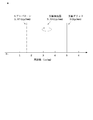
- the moire pattern of the grid (5 lp / mm) is folded back at 3.33 lp / mm. 1.67 lp / mm.
- the conventional X-ray diagnostic apparatus 101 having such a configuration has the following problems. That is, even if the moire pattern is removed from the image in which the moire pattern of the grid 105 is reflected by the moire pattern removal processing unit 121, there is a problem that the moire pattern remains in the image after the removal.
- the present invention has been made in view of such circumstances, and an object thereof is to provide an X-ray diagnostic apparatus and an X-ray diagnostic program for removing a moire pattern remaining in a moire pattern removal image.
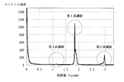
- FIG. 13 shows an example of a one-dimensional Fourier transform result of an image. Specifically, a grid 105 of 50 lines / cm is used for an X-ray detector (FPD) 104 having a pixel pitch of 150 ⁇ m.
- FPD X-ray detector
- the peak frequency of the first harmonic of the moire pattern of the grid 105 is located at about 1.84 lp / mm, and the peak frequency of the second harmonic is located at about 2.98 lp / mm.
- This frequency component is the third harmonic.
- the third harmonic is three times (integer multiple) of the first harmonic and has a frequency of 5.52 lp / mm.
- the frequency of 5.52 lp / mm is folded back at 3.33 lp / mm and appears at a position of 1.14 lp / mm.
- the second harmonic wave has a frequency of 3.68 lp / mm which is twice that of the first harmonic wave, and is folded back and appears at a position of 2.98 lp / mm.
- the third harmonic of the moire pattern was generated in the image after the moire pattern was removed due to the density error of the grid 105.
- the grid density is 50 lines / cm, there are those with 45 to 55 lines / cm. This is because the grid 105 has a grid density tolerance of ⁇ 10% in the Japanese Industrial Standard (JIS).
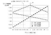
- FIG. 14 is a diagram showing the relationship between the grid error and the peak frequency of the harmonics of the moire pattern.
- the vertical axis indicates the peak frequency (lp / mm) of the first to third harmonics
- the X-ray detector (FPD) 104 is assumed to have a pixel pitch of 150 ⁇ m. In the case of the moire pattern shown in FIG.
- the actual grid density is 48.2 line / cm
- the first harmonic and the third harmonic are almost overlapped, and if the first harmonic is removed, Third harmonics are also removed.
- a shift occurs in the peak frequencies of the first harmonic and the third harmonic. Therefore, the third frequency of the moire pattern remains in the image after removal.
- the third harmonic on the low frequency side is removed particularly when the third harmonic is located on the low frequency side with respect to the other first and second harmonics. Then, information representing a relatively large shape in the image is removed at the same time as the third harmonic, and the visibility is greatly deteriorated. Further, if the third harmonic on the high frequency side is removed, information representing a fine shape or an edge in the image is removed at the same time as the third harmonic.
- the third harmonic is a frequency component having a small spectral intensity, and therefore, the third harmonic is conspicuous in a flat region where the change in pixel value (luminance change) is small in the image, and is recognized outside the flat region. I found out that it was not.
- an X-ray diagnostic apparatus includes an X-ray irradiation unit that irradiates a subject with X-rays, an X-ray detector that detects X-rays transmitted through the subject, and the X-rays of the X-ray detector.
- an X-ray diagnostic apparatus that is arranged on the incident side and that removes scattered X-rays and acquires an image based on the output of the X-ray detector, the moiré pattern of the grid reflected in the image
- a peak frequency detector for detecting a peak frequency of the first harmonic, and removing the first harmonic and the second harmonic of the moire pattern from the image based on the peak frequency of the first harmonic
- a first and second harmonic removal processing unit for obtaining a second harmonic removal image
- a peak frequency of the third harmonic of the moire pattern based on the peak frequency of the first harmonic, and the third harmonic 3rd harmonic extraction field for extracting
- a third harmonic extraction filter creating unit for creating a third harmonic
- a third harmonic extracting unit for extracting the third harmonic from the first and second harmonic removed images based on the third harmonic extraction filter
- a third harmonic subtracting unit that subtracts the extracted third harmonic from the first and second harmonic removed images to obtain a third harmonic removed image.
- the third harmonic extraction filter creation unit calculates the peak frequency of the third harmonic of the moire pattern based on the peak frequency of the first harmonic, and the third harmonic A third harmonic extraction filter for extracting.
- the third harmonic extraction unit extracts the third harmonic from the first and second harmonic removed images based on the third harmonic extraction filter.
- the third harmonic subtraction unit subtracts the extracted third harmonic from the first and second harmonic removal images to obtain a third harmonic removal image. Thereby, the third harmonic of the moire pattern remaining in the moire pattern removal image can be removed.
- the X-ray diagnostic apparatus includes a flatness calculation unit that calculates flatness in the first and second harmonic removal images and obtains flatness information, and a flat region of the flatness information. It is preferable to include an output selection unit that outputs a third harmonic removal image and outputs the first and second harmonic removal images in a region other than the flat region of the flatness information. Since the third harmonic of the moiré pattern is a frequency component having a small spectral intensity, it is conspicuous in a flat area where the luminance change is small in the image, and is not recognized outside the flat area.
- the output selection unit outputs the third harmonic removal image in the flat region out of the flatness information obtained by calculating the flatness by the flatness calculation unit, and the first in the region other than the flatness of the flatness information. -Output a second harmonic removal image. That is, the third harmonic removal image is output only in the flat region where the third harmonic of the moire pattern is conspicuous in the first and second harmonic removal images. Accordingly, it is possible to suppress the deterioration of the visibility of the image and to remove the third harmonic moire pattern remaining in the moire pattern removed image.
- the flatness calculation unit calculates a luminance change amount between the target pixel to be processed and its surrounding pixels, and acquires flatness information. It is preferable to provide. Thereby, the luminance change amount calculation unit acquires flatness information indicating the flatness in the first and second harmonic removed images by calculating the luminance change amount between the target pixel and the surrounding pixels. Can do.
- the luminance change amount calculation unit obtains flatness information by subtracting an average value of the target pixel and surrounding pixels from a pixel value of the target pixel. It is preferable. Thereby, the luminance change amount calculation unit can acquire the flatness information by calculating the luminance change amount by subtracting the addition average value of the target pixel and surrounding pixels from the pixel value of the target pixel. .
- the flatness calculation unit divides the luminance change amount of each pixel of the flatness information by the pixel value of the corresponding first and second harmonic removal images. It is preferable to provide a normalization processing unit that performs normalization processing. That is, a pixel having a high pixel value has a large luminance change amount, and a pixel having a low pixel value tends to have a small luminance change amount. Even if the brightness change amount is the same, the weight change is different between the brightness change amount of the high brightness pixel and the brightness change amount of the low brightness pixel. Therefore, by dividing the luminance change amount of each pixel by the pixel value of the corresponding pixel, the luminance change amounts of the high luminance pixel and the low luminance pixel can be compared on the same basis.
- the flatness calculation unit performs an average of luminance change amounts for each region obtained by dividing the flatness information by a plurality of pixels, and divides the average value. It is preferable to include a smoothing processing unit that applies the smoothing to each pixel in the region. By smoothing the luminance change amount, output selection by the output selection unit can be performed in an arbitrary region. In addition, a region determined as a flat region scattered in a region other than the flat region can be processed as a region other than the flat region. If the third harmonic wave-removed image is output to a flat region scattered in a region other than the flat region, there is a risk that visibility may be deteriorated.
- the X-ray diagnostic apparatus further includes a low-pass filter processing unit that performs one-dimensional low-pass filter processing in a direction along the third harmonic fringes extracted by the third harmonic extraction unit. It is preferable. It is possible to remove a pattern in an oblique direction with respect to the third harmonic fringe extracted in addition to the third harmonic of the moire pattern.
- An X-ray diagnostic program is an X-ray diagnostic program for causing a computer to execute a process of processing an image taken through a grid that removes scattered X-rays.
- a step of detecting a peak frequency of the first harmonic of the reflected moire pattern of the grid, and removing a first harmonic and a second harmonic of the moire pattern from the image based on the peak frequency of the first harmonic And acquiring the first and second harmonic removal images, calculating the peak frequency of the third harmonic of the moire pattern based on the peak frequency of the first harmonic, and extracting the third harmonic
- a third harmonic extraction filter for extracting the third harmonic from the first and second harmonic removal images based on the third harmonic extraction filter, extracted Subtracting the third harmonic from the first and second harmonic removed images to obtain a third harmonic removed image, and causing a computer to execute these steps. is there.
- the peak frequency of the third harmonic of the moire pattern is calculated based on the peak frequency of the first harmonic of the moire pattern, and the third harmonic is extracted.
- Create a third harmonic extraction filter Next, the third harmonic is extracted from the first and second harmonic removed images based on the third harmonic extraction filter. Then, the extracted third harmonic is subtracted from the first and second harmonic removed images to obtain a third harmonic removed image. Thereby, the third harmonic of the moire pattern remaining in the moire pattern removal image can be removed.
- the peak frequency of the third harmonic of the moire pattern is calculated based on the peak frequency of the first harmonic of the moire pattern, and the third harmonic is calculated.
- a third harmonic extraction filter for extraction is created.
- the third harmonic is extracted from the first and second harmonic removed images based on the third harmonic extraction filter.
- the extracted third harmonic is subtracted from the first and second harmonic removed images to obtain a third harmonic removed image.
- the third harmonic of the moire pattern remaining in the moire pattern removal image can be removed.
- FIG. 1 It is a block diagram which shows schematic structure of the X-ray diagnostic apparatus which concerns on an Example. It is a figure where it uses for description of a moire pattern. It is a figure where it uses for description of the extraction filter preparation of the 3rd harmonic of a moire pattern. It is a figure which shows an example of the 3rd harmonic of a moire pattern.
- A) is a figure where it uses for description of a vertical low-pass filter (LPF) process
- (b) is a figure which shows an example of a vertical low-pass filter (LPF).
- LPF vertical low-pass filter
- FIG. 1 is a block diagram illustrating a schematic configuration of an X-ray diagnostic apparatus according to an embodiment
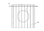
- FIG. 2 is a diagram for explaining a moire pattern
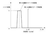
- FIG. 3 is a diagram for explaining the creation of an extraction filter for the third harmonic of the moire pattern
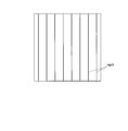
- FIG. 4 is a diagram illustrating an example of the third harmonic of the moire pattern.
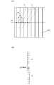
- FIG. 5A is a diagram for explaining the vertical low-pass filter (LPF) processing
- FIG. 5B is a diagram illustrating an example of the vertical low-pass filter (LPF).
- FIG. 6 is a diagram for explaining the third harmonic removal of the moire pattern
- FIG. 7 is a diagram for explaining the calculation of the luminance change amount.
- FIG. 8 is a diagram for explaining the smoothing process
- FIG. 9 is a diagram for explaining the output selection.
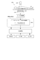
- the X-ray diagnostic apparatus 1 is arranged to face the X-ray tube 3 with the subject M sandwiched between the top plate 2 on which the subject M is placed, the X-ray tube 3 that irradiates the subject M with X-rays, and the subject M. And an X-ray detector 4 for detecting X-rays transmitted through the subject M, and a grid 5 disposed on the X-ray incident side of the X-ray detector 4 for removing scattered X-rays.
- the X-ray tube 3 corresponds to the X-ray irradiation unit in the present invention.
- the X-ray tube 3 is subjected to control necessary for X-ray irradiation by the X-ray tube control unit 6.
- the X-ray tube controller 6 has a high voltage generator 7 that generates the tube voltage and tube current of the X-ray tube 3.
- the X-ray tube control unit 6 irradiates X-rays from the X-ray tube 3 in accordance with X-ray conditions such as a tube voltage, a tube current, and an irradiation time set by an input unit 12 described later.
- the X-ray detector 4 detects X-rays emitted from the X-ray tube 3 and outputs an X-ray detection signal that is a signal corresponding to the X-ray intensity distribution.
- the X-ray detector 4 is configured by a flat panel X-ray detector (FPD), an image intensifier, or the like.
- the X-ray detector 4 is configured with, for example, a 0.15 um pixel pitch and has a resolution of 3.33 lp / mm.
- the grid 5 is configured with a grid density of 50 lines / cm (5 lp / mm), for example.
- the A / D converter 8 and the image processing unit 9 are provided in the subsequent stage of the X-ray detector 4.
- the A / D converter 8 converts the analog X-ray detection signal output from the X-ray detector 4 into a digital signal.
- the image processing unit 9 performs various processes on the image based on the digital X-ray detection signal output from the X-ray detector 4.
- the X-ray diagnostic apparatus 1 includes a main control unit 10 that comprehensively controls each component of the apparatus 1, a display unit 11 that displays an image processed by the image processing unit 9, and an operator that performs input settings and An input unit 12 for performing various operations and a storage unit 13 for storing processed images are provided.
- the main control unit 10 is composed of a central processing unit (CPU) and the like, and executes various programs. For example, the main control unit 10 performs control to move the top 2, the X-ray tube 3 or the X-ray detector 4 on which the subject M is placed to a predetermined position.
- the display unit 11 includes a monitor or the like.
- the input unit 12 includes a keyboard, a mouse, and the like.
- the storage unit 13 includes a storage medium such as a ROM (Read-only Memory), a RAM (Random-Access Memory), or a hard disk.
- the image processing unit 9 includes a first and second harmonic removal processing unit 21 and a third harmonic removal for removing the moire pattern of the grid 5 reflected in the image acquired based on the output of the X-ray detector 4. And a processing unit 23.
- the first and second harmonic removal processing unit 21 includes a peak frequency detection unit 25 that detects the peak frequency of the first harmonic of the moire pattern of the grid 5 reflected in the image.
- the first and second harmonic removal processing unit 21 removes the first and second harmonics of the moire pattern from the image based on the peak frequency of the first harmonic to remove the first and second harmonic removal images. To get.
- the first / second harmonic removal processing unit 21 removes the first harmonic and the second harmonic of the moire pattern of the grid 5 reflected in the image.
- the first and second harmonic removal processing unit 21 first applies a horizontal direction (a direction orthogonal to the fringes of the moire pattern) to the image in which the moire pattern (code mp) is reflected.
- a one-dimensional Fourier transform is performed on the pixel row (reference L1).
- the one-dimensional Fourier transform is performed in order from, for example, the pixel row at the upper end of the image.
- the peak frequency detector 25 detects the peak frequency indicating the first harmonic of the moire pattern from the Fourier transform result (FIG. 13).
- the peak frequency detection unit 25 detects a predetermined peak frequency set from a plurality of peak frequencies detected in order from the upper end of the image. Since the second harmonic is twice (integer multiple) the first harmonic, it is calculated from the peak frequency of the first harmonic. Based on the acquired peak frequencies of the first harmonic and the second harmonic, a filter for extracting the first harmonic and the second harmonic of the moire pattern is created. The first harmonic and the second harmonic are extracted using this filter. Then, the first and second harmonics are removed from the image by subtracting the extracted first and second harmonics from the image in which the moire pattern is reflected. A harmonic removal image is acquired. In FIG. 2, the symbol f indicates a flat region of the subject M in the image.
- the third harmonic removal processing unit 23 includes a storage unit 27, a third harmonic extraction filter creation unit 29, a third harmonic extraction unit 31, a vertical low-pass filter processing unit (vertical LPF processing unit). 33, a third harmonic subtracting unit 35, a flatness calculating unit 37, and an output selecting unit 39.
- the first and second harmonic removal images from which the first and second harmonics of the moire pattern have been removed by the first and second harmonic removal processing unit 21 are stored in the storage unit 27.
- the third harmonic extraction filter creation unit 29 calculates the peak frequency of the third harmonic of the moire pattern based on the peak frequency of the first harmonic, and extracts the third harmonic. Create The peak frequency of the first harmonic detected by the peak frequency detector 25 is given as the peak frequency of the first harmonic.
- the third harmonic is folded at a position of 3.33 lp / mm.
- the case where the peak frequency of the first harmonic is 1.72 lp / mm is when the grid error (ratio) is 0.99 in FIG.
- the third harmonic extraction filter is created by giving a predetermined band to the calculated peak frequency of the third harmonic.
- the third harmonic extraction unit 31 extracts the third harmonic from the first and second harmonic removal images based on the third harmonic extraction filter.
- the first and second harmonic removed images are given by the storage unit 27.
- a filter process using a third harmonic extraction filter is performed on the pixel rows in the horizontal direction of the first and second harmonic removed images. This extraction processing is performed, for example, one column at a time in order from the upper end of the first and second harmonic removed images.
- the third harmonic image of the moire pattern as shown in FIG. 4 is extracted.
- a pattern in an oblique direction is extracted in addition to the third harmonic of the moire pattern, as indicated by reference numeral n in FIG.
- n the third harmonic of the moire pattern
- the vertical LPF processing unit 33 performs one-dimensional low-pass filter (LPF) processing in the vertical direction along the third harmonic fringes extracted by the third harmonic extraction unit 31.
- the fringes of the third harmonic of the moiré pattern are indicated by reference numeral mp3 in FIG. That is, LPF processing is performed in the vertical direction along the third harmonic fringes.
- the filter process shown in FIG. 5B is performed on each pixel of the extracted third harmonic image.
- the filter illustrated in FIG. 5B is a vertical pixel row, and is performed using, for example, 17 pixels including 8 pixels above and below the target pixel to be processed.
- the vertical LPF processing unit 33 corresponds to the low pass filter processing unit in the present invention.
- the third harmonic fringes of the moire pattern are arranged in the horizontal direction, but when the fringes are arranged in the vertical direction, a one-dimensional low-pass filter is formed in the horizontal direction along the fringes. (LPF) processing is performed.
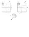
- the third harmonic subtracting unit 35 subtracts the extracted third harmonic from the first and second harmonic removed images to obtain a third harmonic removed image. That is, as shown in FIG. 6, the third harmonic subtraction unit 35 subtracts the third harmonic image P2 extracted from the first and second harmonic removal images P1. Thereby, the 3rd harmonic removal image P3 is acquired.
- the flatness calculation unit 37 calculates flatness in the first and second harmonic removal images and acquires flatness information.
- the calculation of the flatness information by the flatness calculation unit 37 is performed in parallel with the process of acquiring the third harmonic removal image for extracting and removing the third harmonic.
- the flatness information is information for identifying a flat area (flat area) and a non-flat structure area (an area other than the flat area) in the first and second harmonic removal images. For example, in imaging of the leg of the subject M, a flat portion includes a meat portion, and a region other than the flat region includes a bone portion.
- the flatness calculation unit 37 includes a luminance change amount calculation unit 41, a normalization processing unit 43, and a smoothing processing unit 45.
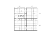
- the luminance change amount calculation unit 41 calculates the luminance change amount between the target pixel to be processed and its surrounding pixels, and acquires flatness information. Specifically, the luminance change amount calculation unit 41 obtains flatness information by subtracting the addition average value of the target pixel and the surrounding pixels from the pixel value of the target pixel. That is, as shown in FIG. 7, the luminance change amount calculation unit 41 performs an average of 21 ⁇ 21 pixels of the target pixel, the target pixel, and, for example, 10 pixels in the upper, lower, left, and right directions, and calculates the average from the pixel value of the target pixel. Subtract the value.
- a pixel having a high pixel value has a large amount of change in luminance (a variation amount of the pixel value), and a pixel having a low pixel value tends to have a small amount of change in luminance. For example, it is assumed that there is a target pixel having a pixel value of 1000 and a target pixel having a pixel value of 10. When both of the luminance change amounts are 2, the luminance change amounts are the same value.
- the luminance change amount between the high luminance pixel and the low luminance pixel can be compared on the same basis.
- the smoothing processing unit 45 performs addition averaging of the luminance change amount for each region obtained by dividing the flatness information by a plurality of pixels, and smoothes the addition average value by applying it to each pixel of the divided region.
- the smoothing processing unit 45 performs addition averaging, for example, by 16 ⁇ 16 pixels and reduces it to one pixel. Then, reduced flatness information P5 of 4 ⁇ 4 pixels is acquired. Then, the flatness information P6 that has been smoothed is obtained by returning (enlarging) the flatness information P5 of 4 ⁇ 4 pixels to the original size of 64 ⁇ 64 pixels.
- the output selection unit 39 outputs the third harmonic removal image in the flat region of the flatness information, and outputs the first and second harmonic removal images in the region other than the flat region of the flatness information. That is, as shown in FIG. 9, the output selection unit 39 outputs either one of the first / second harmonic removal image P1 and the third harmonic removal image P3 based on the flatness information P6. Select whether or not. If the luminance change amount subjected to the normalization process and the smoothing process in the flatness information P6 is equal to or greater than the threshold value, it is identified as a flat area, and if it is less than the threshold value, it is identified as an area other than the flat area.
- the output selection unit is in units of the 16 ⁇ 16 pixel area. 39 is selected and output. As shown in FIG. 9, in the flat region (symbol f) of the flatness information P6, the third harmonic removal image P3 is output. On the other hand, in regions other than the flat region of the flatness information P6, the first and second harmonic removed images P1 are output.
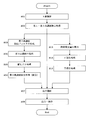
- Step S01 X-ray Imaging
- the X-ray diagnostic apparatus 1 uses an X-ray tube according to X-ray conditions such as tube voltage, tube current and irradiation time set by the X-ray tube controller 6. 3 is irradiated with X-rays. X-rays irradiated from the X-ray tube 3 pass through the subject M and enter the X-ray detector 4. The X-ray detector 4 outputs an X-ray detection signal corresponding to the X-ray intensity distribution.
- the A / D converter 8 converts the analog X-ray detection signal output from the X-ray detector 4 into a digital signal. An image obtained by photographing the subject M can be acquired based on the digitally converted X-ray detection signal.
- Step S02 First / Second Harmonic Elimination Processing
- the peak frequency detection unit 25 detects the peak frequency of the first harmonic of the moiré pattern of the grid reflected in the image.
- the first and second harmonic removal processing unit 21 removes the first and second harmonics of the moire pattern from the image based on the peak frequency of the first harmonic to remove the first and second harmonic removal images. To get.
- Step S03 Creation of Third Harmonic Extraction Filter
- the third harmonic extraction filter creation unit 29 calculates the peak frequency of the third harmonic of the moire pattern based on the peak frequency of the first harmonic, and the third harmonic.
- a third harmonic extraction filter for extracting waves is created (FIG. 3).
- the third harmonic extraction unit 31 extracts the third harmonic from the first and second harmonic removed images based on the third harmonic extraction filter (FIG. 5A )).
- the extraction of the third harmonic is performed, for example, by performing a filter process using the third harmonic extraction filter for each column in order from the upper end of the horizontal pixel column of the first and second harmonic removed images.
- the vertical LPF processing unit 33 is a one-dimensional low-pass filter in the vertical direction along the stripes of the third harmonic (FIG. 5A) extracted by the third harmonic extraction unit 31.
- (LPF) processing is performed.
- the filter shown in FIG. 5B that is, 17 pixels including the upper and lower 8 pixels of the target pixel to be processed is used.
- a new pixel value of the target pixel is set.
- Step S06 Third harmonic removal processing (subtraction) As shown in FIG. 6, the third harmonic subtraction unit 35 subtracts the extracted third harmonic P2 from the first / second harmonic removal image P1 to obtain a third harmonic removal image P3.
- Steps S13 to S15 for calculating the flatness in the first and second harmonic removal images and acquiring the flatness information are performed.
- Step S13 Calculation of luminance change amount
- the normalization processing unit 43 performs normalization processing by dividing the luminance change amount of each pixel of the flatness information by the pixel value of the corresponding first and second harmonic removed images. That is, the luminance change amount C1 is divided by the pixel value B of the target pixel used in the calculation of the luminance change amount C1.
- the smoothing processing unit 45 performs addition averaging of the luminance change amount for each region obtained by dividing the flatness information by a plurality of pixels, and applies the addition average value to each pixel of the divided region. To smooth. That is, as shown in FIG. 8, the smoothing processing unit 45 performs addition averaging with, for example, 16 ⁇ 16 pixels, and reduces it to one pixel. Then, when returning to the original size, the luminance change amount obtained by adding and averaging all the pixels is given to the original size of 16 ⁇ 16 pixels.
- Step S07 Output Selection
- the output selection unit 39 outputs the third harmonic removal image P3 in the flat region f of the flatness information P6, and a region other than the flat region f of the flatness information P6. Then, the first and second harmonic removed images P1 are output. Thus, in the flat region f, the output selection image P7 from which the third harmonic of the moire pattern has been removed is acquired.
- Step S08 Display / Save The output selection image P7 selected for output in step S07 is subjected to other necessary processing in the image processing section 9.
- the output selection image P ⁇ b> 7 is displayed on the display unit 11 and stored in the storage unit 13.
- the third harmonic extraction filter creation unit 29 calculates the peak frequency of the third harmonic of the moire pattern based on the peak frequency of the first harmonic, A third harmonic extraction filter for extracting the third harmonic is created.
- the third harmonic extraction unit 31 extracts the third harmonic from the first and second harmonic removal images based on the third harmonic extraction filter.
- the 3rd harmonic subtraction part 35 subtracts the extracted 3rd harmonic from a 1st, 2nd harmonic removal image, and acquires a 3rd harmonic removal image. Thereby, the third harmonic of the moire pattern remaining in the first and second harmonic removal images can be removed.
- the X-ray diagnostic apparatus 1 calculates the flatness in the first and second harmonic removal images and acquires the flatness information, and the third harmonic in the flat region of the flatness information.
- An output selection unit 39 is provided that outputs the removed image and outputs the first and second harmonic removed images in a region other than the flat region of the flatness information. Since the third harmonic of the moiré pattern is a frequency component having a small spectral intensity, it is conspicuous in a flat area where the luminance change is small in the image, and is not recognized outside the flat area. Therefore, the output selection unit 39 outputs the third harmonic removal image in the flat region among the flatness information obtained by calculating the flatness by the flatness calculation unit 37, and in the region other than the flatness of the flatness information.
- an image having no remaining moire pattern can be obtained without deteriorating the visibility except in a flat region.
- the luminance change is small, and even if the third harmonic of the moire pattern is removed, it is relatively difficult to be affected by the visibility deterioration. Further, since the third harmonic of the moire pattern in the flat region is removed, it is possible to improve the S / N ratio in the flat region.
- the luminance change amount calculation unit 41 acquires flatness information indicating the flatness in the first and second harmonic removed images by calculating the luminance change amount between the target pixel and the surrounding pixels. Can do. Further, the luminance change amount calculation unit 41 can acquire the flatness information by calculating the luminance change amount by subtracting the addition average value of the target pixel and the surrounding pixels from the pixel value of the target pixel. .
- the normalization processing unit 43 performs normalization processing by dividing the luminance change amount of each pixel of the flatness information by the pixel value of the corresponding first / second harmonic removed image. That is, a pixel having a high pixel value has a large luminance change amount, and a pixel having a low pixel value tends to have a small luminance change amount. Even if the brightness change amount is the same, the weight change is different between the brightness change amount of the high brightness pixel and the brightness change amount of the low brightness pixel. Therefore, by dividing the luminance change amount of each pixel by the pixel value of the corresponding pixel, the luminance change amounts of the high luminance pixel and the low luminance pixel can be compared on the same basis.
- the smoothing processing unit 45 performs addition averaging of the luminance change amount for each region obtained by dividing the flatness information by a plurality of pixels (for example, 16 ⁇ 16 pixels), and each pixel of the region obtained by dividing the addition average value. (16 ⁇ 16 pixels) is applied for smoothing.
- Image output selection by the output selection unit 39 is not performed on a pixel basis, but can be performed in an arbitrary region by smoothing.
- a region determined as a flat region scattered in a region other than the flat region can be processed as a region other than the flat region. If the third harmonic wave-removed image is output to a flat region scattered in a region other than the flat region, there is a risk that visibility may be deteriorated.
- the vertical LPF processing unit 33 performs one-dimensional LPF processing in the vertical direction along the third harmonic fringes extracted by the third harmonic extraction unit 31. It is possible to remove a pattern in an oblique direction with respect to the third harmonic fringe extracted in addition to the third harmonic of the moire pattern.
- the present invention is not limited to the above embodiment, and can be modified as follows.
- the image processing unit 9 includes a control unit configured by a CPU or the like for executing a program, and a storage unit configured by a storage medium such as a ROM or RAM that stores the program or the like. May be provided.
- the storage unit may store a program for the operations of steps S01 to S08 and S13 to S15, and the program may be executed by the control unit. In this case, operations necessary for this program are input through the input unit 12, and the output selection image P ⁇ b> 7 is displayed on the display unit 11.
- each of steps S01 to S08 and S13 to S15 is not limited to the image processing unit 9, and the operation program is stored in the storage unit 13 and executed by the main control unit 10. You may do it. In this case, operations necessary for this program are input through the input unit 12, and the output selection image P ⁇ b> 7 is displayed on the display unit 11.
- the operation program may be executed on a personal computer connected to the X-ray diagnostic apparatus 1 in a network system such as a LAN.
Landscapes
- Engineering & Computer Science (AREA)
- Health & Medical Sciences (AREA)
- Life Sciences & Earth Sciences (AREA)
- Physics & Mathematics (AREA)
- Medical Informatics (AREA)
- Theoretical Computer Science (AREA)
- General Physics & Mathematics (AREA)
- Radiology & Medical Imaging (AREA)
- General Health & Medical Sciences (AREA)
- Nuclear Medicine, Radiotherapy & Molecular Imaging (AREA)
- Biomedical Technology (AREA)
- High Energy & Nuclear Physics (AREA)
- Optics & Photonics (AREA)
- Heart & Thoracic Surgery (AREA)
- Molecular Biology (AREA)
- Surgery (AREA)
- Animal Behavior & Ethology (AREA)
- Pathology (AREA)
- Public Health (AREA)
- Veterinary Medicine (AREA)
- Biophysics (AREA)
- Computer Vision & Pattern Recognition (AREA)
- Quality & Reliability (AREA)
- Apparatus For Radiation Diagnosis (AREA)
- Image Processing (AREA)
Abstract
Description
Ny=1/(2×δ)…(1)
3 … X線管
4 … X線検出器
5 … 散乱線除去グリッド
9 … 画像処理部
10 … 主制御部
21 … 第1・第2高調波除去処理部
23 … 第3高調波除去処理部
25 … ピーク周波数検出部
29 … 第3高調波抽出フィルタ作成部
31 … 第3高調波抽出部
33 … 縦ローパスフィルタ処理部(縦LPF処理部)
35 … 第3高調波減算部
37 … 平坦度算出部
39 … 出力選択部
41 … 輝度変化量算出部
43 … 正規化処理部
45 … 平滑化処理部
X線診断装置1は、図1に示すように、X線管制御部6で設定された管電圧や管電流や照射時間等のX線条件に応じてX線管3からX線を照射させる。X線管3から照射されたX線は、被検体Mを透過してX線検出器4に入射する。X線検出器4は、X線強度分布に応じたX線検出信号を出力する。A/D変換器8は、X線検出器4から出力されたアナログのX線検出信号をデジタル信号に変換する。このデジタル変換されたX線検出信号に基づいて被検体Mを撮影した画像を取得することができる。
ピーク周波数検出部25は、画像に映りこんだ前記グリッドのモアレパターンの第1高調波のピーク周波数を検出する。第1・第2高調波除去処理部21は、第1高調波のピーク周波数に基づいて画像からモアレパターンの第1高調波と第2高調波を除去して第1・第2高調波除去画像を取得する。
第3高調波抽出フィルタ作成部29は、第1高調波のピーク周波数に基づいてモアレパターンの第3高調波のピーク周波数を算出し、第3高調波を抽出するための第3高調波抽出フィルタを作成する(図3)。
第3高調波抽出部31は、第3高調波抽出フィルタに基づいて第1・第2高調波除去画像から第3高調波を抽出する(図5(a))。第3高調波の抽出は、例えば、1・第2高調波除去画像の横方向の画素列の上端から順番に1列ずつに第3高調波抽出フィルタを用いたフィルタ処理を施して行われる。
縦LPF処理部33は、第3高調波抽出部31で抽出された第3高調波(図5(a))の縞目に沿った縦方向に1次元のローパスフィルタ(LPF)処理を行う。縦方向のLPF処理は、例えば、図5(b)に示すフィルタ、すなわち、処理対象の注目画素の上下8画素を含む17画素を用い、この17画素の処理前の画素値の加算平均値を注目画素の新たな画素値とする。この処理を各画素で行うことにより、画像の縦方向の画素が平滑化されて図5(a)に示す符号nの斜め方向のパターンを除去される。そのため、図4に示すようなモアレパターンの第3高調波の画像を取得することができる。
第3高調波減算部35は、図6に示すように、抽出された第3高調波P2を第1・第2高調波除去画像P1から減算して第3高調波除去画像P3を取得する。
輝度変化量算出部41は、注目画素の画素値から注目画素とその周囲の画素との加算平均値を減算して平坦度情報を取得する。すなわち、輝度変化量算出部41は、図7に示すように、注目画素を含む21×21画素の画素値の加算平均値をAとし、注目画素の画素値をBとして、輝度変化量C1=|B-A|を算出する。この処理を各画素で行うことにより、新たな画像として平坦度情報として取得する。
正規化処理部43は、平坦度情報の各画素の輝度変化量をそれぞれ対応する第1・第2高調波除去画像の画素値で除算して正規化処理する。すなわち、輝度変化量C1の算出で用いた注目画素の画素値Bで輝度変化量C1を除算する。正規化処理後の輝度変化量C2は、C2=|B-A|/Bで算出される。
平滑化処理部45は、平坦度情報を複数個の画素で分割した領域ごとに輝度変化量の加算平均を行い、その加算平均値を分割した領域の各画素に適用させて平滑化する。すなわち、平滑化処理部45は、図8に示すように、例えば16×16画素で加算平均を行って1画素に縮小する。そして、元の大きさに戻す際に、元の大きさの16×16画素には、全画素に加算平均された輝度変化量が与えられる。
出力選択部39は、図9に示すように、平坦度情報P6の平坦領域fでは第3高調波除去画像P3を出力し、平坦度情報P6の平坦領域f以外の領域では第1・第2高調波除去画像P1を出力する。このように平坦領域fではモアレパターンの第3高調波が除去された出力選択画像P7が取得される。
ステップS07で出力選択された出力選択画像P7は、画像処理部9でその他必要な処理が行われる。そして、出力選択画像P7は、表示部11に表示され、また、記憶部13に記憶される。
Claims (8)
- 被検体にX線を照射するX線照射部と、
被検体を透過したX線を検出するX線検出器と、
前記X線検出器のX線入射側に配置され、散乱したX線を除去するグリッドとを備え、
前記X線検出器の出力に基づいて画像を取得するX線診断装置において、
前記画像に映りこんだ前記グリッドのモアレパターンの第1高調波のピーク周波数を検出するピーク周波数検出部と、
前記第1高調波のピーク周波数に基づいて前記画像からモアレパターンの第1高調波と第2高調波を除去して第1・第2高調波除去画像を取得する第1・第2高調波除去処理部と、
前記第1高調波のピーク周波数に基づいてモアレパターンの第3高調波のピーク周波数を算出し、前記第3高調波を抽出するための第3高調波抽出フィルタを作成する第3高調波抽出フィルタ作成部と、
前記第3高調波抽出フィルタに基づいて前記第1・第2高調波除去画像から前記第3高調波を抽出する第3高調波抽出部と、
抽出された前記第3高調波を前記第1・第2高調波除去画像から減算して第3高調波除去画像を取得する第3高調波減算部と、
を備えていることを特徴とするX線診断装置。 - 請求項1に記載のX線診断装置において、
前記第1・第2高調波除去画像内の平坦度を算出して平坦度情報を取得する平坦度算出部と、
前記平坦度情報の平坦領域では第3高調波除去画像を出力し、前記平坦度情報の平坦領域以外の領域では前記第1・第2高調波除去画像を出力する出力選択部とを備えていることを特徴とするX線診断装置。 - 請求項2に記載のX線診断装置において、
前記平坦度算出部は、処理対象である注目画素とその周囲の画素との輝度変化量を算出して平坦度情報を取得する輝度変化量算出部を備えていることを特徴とするX線診断装置。 - 請求項3に記載のX線診断装置において、
前記輝度変化量算出部は、前記注目画素の画素値から前記注目画素とその周囲の画素との加算平均値を減算して平坦度情報を取得することを特徴とするX線診断装置。 - 請求項3または4に記載のX線診断装置において、
前記平坦度算出部は、前記平坦度情報の各画素の輝度変化量をそれぞれ対応する前記第1・第2高調波除去画像の画素値で除算して正規化処理する正規化処理部を備えていることを特徴とするX線診断装置。 - 請求項3から5のいずれかに記載のX線診断装置において、
前記平坦度算出部は、前記平坦度情報を複数個の画素で分割した領域ごとに輝度変化量の加算平均を行い、その加算平均値を分割した領域の各画素に適用させて平滑化する平滑化処理部を備えていることを特徴とするX線診断装置。 - 請求項1から6のいずれかに記載のX線診断装置において、
前記第3高調波抽出部で抽出された前記第3高調波の縞目に沿った方向に1次元のローパスフィルタ処理を行うローパスフィルタ処理部を備えていることを特徴とするX線診断装置。 - 散乱したX線を除去するグリッドを介して撮影された画像の処理工程をコンピュータに実行させるためのX線診断用プログラムであって、
前記画像に映りこんだ前記グリッドのモアレパターンの第1高調波のピーク周波数を検出する工程と、
前記第1高調波のピーク周波数に基づいて前記画像からモアレパターンの第1高調波と第2高調波を除去して第1・第2高調波除去画像を取得する工程と、
前記第1高調波のピーク周波数に基づいてモアレパターンの第3高調波のピーク周波数を算出し、前記第3高調波を抽出するための第3高調波抽出フィルタを作成する工程と、
前記第3高調波抽出フィルタに基づいて前記第1・第2高調波除去画像から前記第3高調波を抽出する工程と、
抽出された前記第3高調波を前記第1・第2高調波除去画像から減算して第3高調波除去画像を取得する工程と、を備え、
これらの工程をコンピュータに実行させることを特徴とするX線診断用プログラム。
Priority Applications (5)
| Application Number | Priority Date | Filing Date | Title |
|---|---|---|---|
| EP11864008.5A EP2700359B1 (en) | 2011-04-22 | 2011-04-22 | X-ray diagnostic apparatus and x-ray diagnostic program |
| PCT/JP2011/002377 WO2012143979A1 (ja) | 2011-04-22 | 2011-04-22 | X線診断装置およびx線診断用プログラム |
| JP2013510742A JP5527481B2 (ja) | 2011-04-22 | 2011-04-22 | X線診断装置およびx線診断用プログラム |
| US14/113,176 US9232925B2 (en) | 2011-04-22 | 2011-04-22 | X-ray diagnostic apparatus and storage medium storing X-ray diagnostic program |
| CN201180070344.4A CN103491875B (zh) | 2011-04-22 | 2011-04-22 | X射线诊断装置以及莫尔条纹去除方法 |
Applications Claiming Priority (1)
| Application Number | Priority Date | Filing Date | Title |
|---|---|---|---|
| PCT/JP2011/002377 WO2012143979A1 (ja) | 2011-04-22 | 2011-04-22 | X線診断装置およびx線診断用プログラム |
Publications (1)
| Publication Number | Publication Date |
|---|---|
| WO2012143979A1 true WO2012143979A1 (ja) | 2012-10-26 |
Family
ID=47041134
Family Applications (1)
| Application Number | Title | Priority Date | Filing Date |
|---|---|---|---|
| PCT/JP2011/002377 Ceased WO2012143979A1 (ja) | 2011-04-22 | 2011-04-22 | X線診断装置およびx線診断用プログラム |
Country Status (5)
| Country | Link |
|---|---|
| US (1) | US9232925B2 (ja) |
| EP (1) | EP2700359B1 (ja) |
| JP (1) | JP5527481B2 (ja) |
| CN (1) | CN103491875B (ja) |
| WO (1) | WO2012143979A1 (ja) |
Cited By (3)
| Publication number | Priority date | Publication date | Assignee | Title |
|---|---|---|---|---|
| JP2015208638A (ja) * | 2014-04-30 | 2015-11-24 | 株式会社東芝 | X線診断装置及び画像処理装置 |
| WO2017138097A1 (ja) * | 2016-02-09 | 2017-08-17 | 株式会社島津製作所 | X線撮影装置 |
| JP7551703B2 (ja) | 2022-07-20 | 2024-09-17 | キヤノン株式会社 | 画像処理装置、画像処理方法、およびプログラム |
Families Citing this family (3)
| Publication number | Priority date | Publication date | Assignee | Title |
|---|---|---|---|---|
| JP6169626B2 (ja) * | 2014-03-10 | 2017-07-26 | 富士フイルム株式会社 | 放射線画像処理装置、方法およびプログラム |
| CN105832359B (zh) * | 2016-03-22 | 2018-10-19 | 广州七喜医疗设备有限公司 | 一种自适应x线滤线栅栅影去除的方法 |
| JP2024025163A (ja) * | 2022-08-10 | 2024-02-26 | キヤノン株式会社 | 放射線撮影装置及びその制御方法、放射線撮影システム、プログラム |
Citations (5)
| Publication number | Priority date | Publication date | Assignee | Title |
|---|---|---|---|---|
| JP2002152467A (ja) | 2000-08-28 | 2002-05-24 | Fuji Photo Film Co Ltd | 画像信号生成方法および装置並びにプログラム |
| JP2003319260A (ja) * | 2002-04-25 | 2003-11-07 | Fuji Photo Film Co Ltd | 画像信号生成方法および装置 |
| JP2005052553A (ja) * | 2003-08-07 | 2005-03-03 | Canon Inc | 放射線画像処理方法及び装置並びにグリッドの選別方法及び装置 |
| JP2010240259A (ja) * | 2009-04-08 | 2010-10-28 | Shimadzu Corp | 放射線撮像装置 |
| JP2011010873A (ja) * | 2009-07-02 | 2011-01-20 | Shimadzu Corp | 放射線撮影装置 |
Family Cites Families (8)
| Publication number | Priority date | Publication date | Assignee | Title |
|---|---|---|---|---|
| DE69522844T2 (de) * | 1994-02-16 | 2002-05-16 | Koninklijke Philips Electronics N.V., Eindhoven | Bildverarbeitungsverfahren zur örtlichen Bestimmung des Zentrums und der Objekte, die sich gegen einen Hintergrund abheben, und Vorrichtung zur Durchführung des Verfahrens |
| EP1202555A3 (en) | 2000-08-28 | 2004-12-29 | Fuji Photo Film Co., Ltd. | Image signal generating method, apparatus and program |
| JP4118535B2 (ja) * | 2001-07-03 | 2008-07-16 | 株式会社日立メディコ | X線検査装置 |
| JP2003233818A (ja) * | 2002-02-06 | 2003-08-22 | Fuji Photo Film Co Ltd | 周期的パターン判定方法および装置並びにプログラム |
| US7796792B2 (en) * | 2005-06-29 | 2010-09-14 | Agfa Healthcare, N.V. | Method of identifying disturbing frequencies originating from the presence of an anti-scatter grid during acquisition of a radiation image |
| CN100510725C (zh) * | 2006-11-14 | 2009-07-08 | 北京国药恒瑞美联信息技术有限公司 | 用于消除散射辐射影响的虚拟滤线栅成像方法及其系统 |
| CN101743565B (zh) * | 2007-03-06 | 2012-08-08 | 皇家飞利浦电子股份有限公司 | 图像序列的滤波 |
| EP2196148B1 (en) * | 2007-10-02 | 2015-03-04 | Shimadzu Corporation | Radiological image processing apparatus and radiological image processing program |
-
2011
- 2011-04-22 US US14/113,176 patent/US9232925B2/en active Active
- 2011-04-22 CN CN201180070344.4A patent/CN103491875B/zh not_active Expired - Fee Related
- 2011-04-22 EP EP11864008.5A patent/EP2700359B1/en not_active Not-in-force
- 2011-04-22 JP JP2013510742A patent/JP5527481B2/ja active Active
- 2011-04-22 WO PCT/JP2011/002377 patent/WO2012143979A1/ja not_active Ceased
Patent Citations (5)
| Publication number | Priority date | Publication date | Assignee | Title |
|---|---|---|---|---|
| JP2002152467A (ja) | 2000-08-28 | 2002-05-24 | Fuji Photo Film Co Ltd | 画像信号生成方法および装置並びにプログラム |
| JP2003319260A (ja) * | 2002-04-25 | 2003-11-07 | Fuji Photo Film Co Ltd | 画像信号生成方法および装置 |
| JP2005052553A (ja) * | 2003-08-07 | 2005-03-03 | Canon Inc | 放射線画像処理方法及び装置並びにグリッドの選別方法及び装置 |
| JP2010240259A (ja) * | 2009-04-08 | 2010-10-28 | Shimadzu Corp | 放射線撮像装置 |
| JP2011010873A (ja) * | 2009-07-02 | 2011-01-20 | Shimadzu Corp | 放射線撮影装置 |
Non-Patent Citations (1)
| Title |
|---|
| See also references of EP2700359A4 |
Cited By (3)
| Publication number | Priority date | Publication date | Assignee | Title |
|---|---|---|---|---|
| JP2015208638A (ja) * | 2014-04-30 | 2015-11-24 | 株式会社東芝 | X線診断装置及び画像処理装置 |
| WO2017138097A1 (ja) * | 2016-02-09 | 2017-08-17 | 株式会社島津製作所 | X線撮影装置 |
| JP7551703B2 (ja) | 2022-07-20 | 2024-09-17 | キヤノン株式会社 | 画像処理装置、画像処理方法、およびプログラム |
Also Published As
| Publication number | Publication date |
|---|---|
| US20140086472A1 (en) | 2014-03-27 |
| US9232925B2 (en) | 2016-01-12 |
| EP2700359A1 (en) | 2014-02-26 |
| JP5527481B2 (ja) | 2014-06-18 |
| JPWO2012143979A1 (ja) | 2014-07-28 |
| EP2700359B1 (en) | 2015-07-15 |
| CN103491875A (zh) | 2014-01-01 |
| CN103491875B (zh) | 2015-09-30 |
| EP2700359A4 (en) | 2014-09-03 |
Similar Documents
| Publication | Publication Date | Title |
|---|---|---|
| JP5527481B2 (ja) | X線診断装置およびx線診断用プログラム | |
| JP6105586B2 (ja) | エネルギー高感度検出の微分位相コントラストイメージング | |
| US9820713B2 (en) | Image processing apparatus, radiation imaging system, control method, and storage medium | |
| JP5848697B2 (ja) | X線画像診断装置 | |
| JP6215011B2 (ja) | X線診断装置 | |
| JP2013102951A (ja) | 撮像装置および画像処理方法 | |
| WO2013035255A1 (ja) | 画像処理装置およびそれを備えた放射線撮影装置 | |
| CN107203983A (zh) | 用于减少x射线图像中的栅线伪影的方法及系统 | |
| JP2011136102A (ja) | 放射線撮像装置 | |
| JP2019122616A (ja) | 画像処理装置、画像処理方法、及び画像処理プログラム | |
| JP5699842B2 (ja) | 画質評価方法およびそれを用いたx線透視撮影装置 | |
| JP5821790B2 (ja) | X線診断装置 | |
| JP5360397B2 (ja) | 放射線撮影装置 | |
| JP2018029777A (ja) | X線位相差撮像装置 | |
| JP2014176565A (ja) | 画像処理装置、放射線撮影装置、画像処理方法、コンピュータプログラム及び記憶媒体 | |
| JP2018038638A (ja) | 画像処理装置、方法およびプログラム | |
| US20200229785A1 (en) | A device and method for scatter correction in an x-ray image | |
| US10335109B2 (en) | Radiation phase-contrast imaging device | |
| JP5077587B2 (ja) | 放射線撮像装置 | |
| Strauss et al. | Image quality dependence on image processing software in computed radiography | |
| US8897418B2 (en) | X-ray apparatus | |
| JP5407937B2 (ja) | X線撮影装置 | |
| JP6677263B2 (ja) | X線撮影装置 | |
| US8867699B2 (en) | Radiographic device | |
| JP2002330344A (ja) | 放射線画像処理装置、画像処理システム、放射線画像処理方法、記憶媒体、及びプログラム |
Legal Events
| Date | Code | Title | Description |
|---|---|---|---|
| 121 | Ep: the epo has been informed by wipo that ep was designated in this application |
Ref document number: 11864008 Country of ref document: EP Kind code of ref document: A1 |
|
| ENP | Entry into the national phase |
Ref document number: 2013510742 Country of ref document: JP Kind code of ref document: A |
|
| WWE | Wipo information: entry into national phase |
Ref document number: 14113176 Country of ref document: US |
|
| NENP | Non-entry into the national phase |
Ref country code: DE |
|
| WWE | Wipo information: entry into national phase |
Ref document number: 2011864008 Country of ref document: EP |