WO2012143986A1 - 車両用駆動力伝達装置の製造方法及び製造装置 - Google Patents
車両用駆動力伝達装置の製造方法及び製造装置 Download PDFInfo
- Publication number
- WO2012143986A1 WO2012143986A1 PCT/JP2011/059491 JP2011059491W WO2012143986A1 WO 2012143986 A1 WO2012143986 A1 WO 2012143986A1 JP 2011059491 W JP2011059491 W JP 2011059491W WO 2012143986 A1 WO2012143986 A1 WO 2012143986A1
- Authority
- WO
- WIPO (PCT)
- Prior art keywords
- case
- annular flange
- driving force
- ring gear
- welding
- Prior art date
- Legal status (The legal status is an assumption and is not a legal conclusion. Google has not performed a legal analysis and makes no representation as to the accuracy of the status listed.)
- Ceased
Links
Images


Classifications
-
- B—PERFORMING OPERATIONS; TRANSPORTING
- B23—MACHINE TOOLS; METAL-WORKING NOT OTHERWISE PROVIDED FOR
- B23K—SOLDERING OR UNSOLDERING; WELDING; CLADDING OR PLATING BY SOLDERING OR WELDING; CUTTING BY APPLYING HEAT LOCALLY, e.g. FLAME CUTTING; WORKING BY LASER BEAM
- B23K2103/00—Materials to be soldered, welded or cut
- B23K2103/50—Inorganic materials other than metals or composite materials
-
- B—PERFORMING OPERATIONS; TRANSPORTING
- B23—MACHINE TOOLS; METAL-WORKING NOT OTHERWISE PROVIDED FOR
- B23K—SOLDERING OR UNSOLDERING; WELDING; CLADDING OR PLATING BY SOLDERING OR WELDING; CUTTING BY APPLYING HEAT LOCALLY, e.g. FLAME CUTTING; WORKING BY LASER BEAM
- B23K26/00—Working by laser beam, e.g. welding, cutting or boring
- B23K26/08—Devices involving relative movement between laser beam and workpiece
- B23K26/0823—Devices involving rotation of the workpiece
-
- B—PERFORMING OPERATIONS; TRANSPORTING
- B23—MACHINE TOOLS; METAL-WORKING NOT OTHERWISE PROVIDED FOR
- B23K—SOLDERING OR UNSOLDERING; WELDING; CLADDING OR PLATING BY SOLDERING OR WELDING; CUTTING BY APPLYING HEAT LOCALLY, e.g. FLAME CUTTING; WORKING BY LASER BEAM
- B23K26/00—Working by laser beam, e.g. welding, cutting or boring
- B23K26/20—Bonding
- B23K26/21—Bonding by welding
- B23K26/211—Bonding by welding with interposition of special material to facilitate connection of the parts
-
- B—PERFORMING OPERATIONS; TRANSPORTING
- B23—MACHINE TOOLS; METAL-WORKING NOT OTHERWISE PROVIDED FOR
- B23K—SOLDERING OR UNSOLDERING; WELDING; CLADDING OR PLATING BY SOLDERING OR WELDING; CUTTING BY APPLYING HEAT LOCALLY, e.g. FLAME CUTTING; WORKING BY LASER BEAM
- B23K26/00—Working by laser beam, e.g. welding, cutting or boring
- B23K26/20—Bonding
- B23K26/21—Bonding by welding
- B23K26/24—Seam welding
- B23K26/244—Overlap seam welding
-
- B—PERFORMING OPERATIONS; TRANSPORTING
- B23—MACHINE TOOLS; METAL-WORKING NOT OTHERWISE PROVIDED FOR
- B23K—SOLDERING OR UNSOLDERING; WELDING; CLADDING OR PLATING BY SOLDERING OR WELDING; CUTTING BY APPLYING HEAT LOCALLY, e.g. FLAME CUTTING; WORKING BY LASER BEAM
- B23K26/00—Working by laser beam, e.g. welding, cutting or boring
- B23K26/20—Bonding
- B23K26/21—Bonding by welding
- B23K26/24—Seam welding
- B23K26/28—Seam welding of curved planar seams
- B23K26/282—Seam welding of curved planar seams of tube sections
-
- B—PERFORMING OPERATIONS; TRANSPORTING
- B23—MACHINE TOOLS; METAL-WORKING NOT OTHERWISE PROVIDED FOR
- B23K—SOLDERING OR UNSOLDERING; WELDING; CLADDING OR PLATING BY SOLDERING OR WELDING; CUTTING BY APPLYING HEAT LOCALLY, e.g. FLAME CUTTING; WORKING BY LASER BEAM
- B23K26/00—Working by laser beam, e.g. welding, cutting or boring
- B23K26/20—Bonding
- B23K26/32—Bonding taking account of the properties of the material involved
-
- B—PERFORMING OPERATIONS; TRANSPORTING
- B23—MACHINE TOOLS; METAL-WORKING NOT OTHERWISE PROVIDED FOR
- B23K—SOLDERING OR UNSOLDERING; WELDING; CLADDING OR PLATING BY SOLDERING OR WELDING; CUTTING BY APPLYING HEAT LOCALLY, e.g. FLAME CUTTING; WORKING BY LASER BEAM
- B23K31/00—Processes relevant to this subclass, specially adapted for particular articles or purposes, but not covered by any single one of main groups B23K1/00 - B23K28/00
- B23K31/12—Processes relevant to this subclass, specially adapted for particular articles or purposes, but not covered by any single one of main groups B23K1/00 - B23K28/00 relating to investigating the properties, e.g. the weldability, of materials
- B23K31/125—Weld quality monitoring
-
- F—MECHANICAL ENGINEERING; LIGHTING; HEATING; WEAPONS; BLASTING
- F16—ENGINEERING ELEMENTS AND UNITS; GENERAL MEASURES FOR PRODUCING AND MAINTAINING EFFECTIVE FUNCTIONING OF MACHINES OR INSTALLATIONS; THERMAL INSULATION IN GENERAL
- F16H—GEARING
- F16H48/00—Differential gearings
- F16H48/38—Constructional details
-
- G—PHYSICS
- G01—MEASURING; TESTING
- G01M—TESTING STATIC OR DYNAMIC BALANCE OF MACHINES OR STRUCTURES; TESTING OF STRUCTURES OR APPARATUS, NOT OTHERWISE PROVIDED FOR
- G01M13/00—Testing of machine parts
- G01M13/02—Gearings; Transmission mechanisms
- G01M13/021—Gearings
-
- B—PERFORMING OPERATIONS; TRANSPORTING
- B23—MACHINE TOOLS; METAL-WORKING NOT OTHERWISE PROVIDED FOR
- B23K—SOLDERING OR UNSOLDERING; WELDING; CLADDING OR PLATING BY SOLDERING OR WELDING; CUTTING BY APPLYING HEAT LOCALLY, e.g. FLAME CUTTING; WORKING BY LASER BEAM
- B23K2101/00—Articles made by soldering, welding or cutting
- B23K2101/006—Vehicles
-
- B—PERFORMING OPERATIONS; TRANSPORTING
- B23—MACHINE TOOLS; METAL-WORKING NOT OTHERWISE PROVIDED FOR
- B23K—SOLDERING OR UNSOLDERING; WELDING; CLADDING OR PLATING BY SOLDERING OR WELDING; CUTTING BY APPLYING HEAT LOCALLY, e.g. FLAME CUTTING; WORKING BY LASER BEAM
- B23K2101/00—Articles made by soldering, welding or cutting
- B23K2101/008—Gears
-
- B—PERFORMING OPERATIONS; TRANSPORTING
- B23—MACHINE TOOLS; METAL-WORKING NOT OTHERWISE PROVIDED FOR
- B23K—SOLDERING OR UNSOLDERING; WELDING; CLADDING OR PLATING BY SOLDERING OR WELDING; CUTTING BY APPLYING HEAT LOCALLY, e.g. FLAME CUTTING; WORKING BY LASER BEAM
- B23K2103/00—Materials to be soldered, welded or cut
- B23K2103/02—Iron or ferrous alloys
- B23K2103/04—Steel or steel alloys
-
- F—MECHANICAL ENGINEERING; LIGHTING; HEATING; WEAPONS; BLASTING
- F16—ENGINEERING ELEMENTS AND UNITS; GENERAL MEASURES FOR PRODUCING AND MAINTAINING EFFECTIVE FUNCTIONING OF MACHINES OR INSTALLATIONS; THERMAL INSULATION IN GENERAL
- F16H—GEARING
- F16H48/00—Differential gearings
- F16H48/38—Constructional details
- F16H2048/382—Methods for manufacturing differential gearings
-
- F—MECHANICAL ENGINEERING; LIGHTING; HEATING; WEAPONS; BLASTING
- F16—ENGINEERING ELEMENTS AND UNITS; GENERAL MEASURES FOR PRODUCING AND MAINTAINING EFFECTIVE FUNCTIONING OF MACHINES OR INSTALLATIONS; THERMAL INSULATION IN GENERAL
- F16H—GEARING
- F16H48/00—Differential gearings
- F16H48/38—Constructional details
- F16H2048/385—Constructional details of the ring or crown gear
Definitions
- the present invention relates to a manufacturing method and a manufacturing apparatus for a vehicle driving force transmission device that transmits a driving force from a driving source such as an engine to driving wheels.
- the differential gear device 300 As a vehicle driving force transmission device that transmits a driving force from a driving source such as an engine to driving wheels, there is a differential gear (hereinafter referred to as “diff gear”) device including a differential gear, for example.
- the differential gear device 300 includes a differential case 301 (hereinafter referred to as “differential case” or simply “case”), side gears 314 and 315 and pinion gears 312 and 313 mounted inside the differential case 301, and a differential case. And a ring gear 302 fixed to the outer peripheral surface of 301.
- An annular flange 310 is formed on the outer peripheral surface of the conventional differential case 301, and the ring gear 302 is bolted to the flange 310.
- the differential case 301 has been conventionally formed by casting spheroidal graphite cast iron or the like to cope with a complicated shape
- the ring gear 302 has been formed by machining or forging chromium molybdenum steel or the like because it is a strength member. Yes. Therefore, when the welding method is adopted as a method for fixing the differential case 301 and the ring gear 302, which are parts of different materials, there is a problem that cracks are likely to occur at the welded portion.
- the ring gear 302 is an annular member, it is necessary to wrap the bead when the entire circumference is welded at the start end and the end, but the lap portion of the weld bead is heat input twice. However, shrinkage is large and cracking is likely to occur.
- a displacement meter that measures the displacement of the surface of the welded structure
- a deformation amount calculation device that calculates the amount of deformation of the welded structure from the data from the displacement meter and position information about the displacement measurement point, and the surface of the welded structure
- a temperature meter that measures the temperature
- a temperature distribution calculation device that estimates the temperature distribution of the welded structure from the data from this thermometer and position information about the temperature measurement point, and a judgment on the welding deformation of the welded structure during welding
- a determination device that performs a first calculation unit that estimates the amount of thermal deformation due to linear expansion of the welded structure from the temperature distribution of the welded structure obtained by the temperature distribution calculation device, and a deformation amount calculation.
- a welding structure deformation monitoring device for monitoring the welding deformation of a welded structure is disclosed in Patent Document 2.
- the true amount of welding deformation caused by the elasto-plastic deformation of the weld can be obtained. Can monitor deformation during the process.
- Patent Document 1 since the technique disclosed in Patent Document 1 is a method of measuring the temporal change in the amount of dynamic strain, a certain amount of time is required to determine whether or not cracking has occurred. Therefore, in order to measure a welding location in a short time, it is necessary to divide the range and irradiate a plurality of laser beams and provide a plurality of locations to be measured simultaneously. In this case, since the laser irradiation apparatus is expensive, as a result, the inspection cost increases, so that it is difficult to introduce it into the actual line.
- Patent Document 2 is a method of subtracting the amount of thermal deformation due to linear expansion caused by the temperature distribution and obtaining the true amount of welding deformation caused by the elasto-plastic deformation of the welded portion. It is suitable for monitoring large structures with large thermal deformation due to the above, but it is difficult to apply to small parts such as a vehicle driving force transmission device. Moreover, it is necessary to install a plurality of thermometers in addition to the displacement meter, and it cannot be said that the method can be simply measured.
- vibrations from the driving source and vibrations from the wheels are transmitted to the vehicle driving force transmission device. Therefore, if a crack exists in the welded portion between the case and the ring gear, it can cause a decrease in fatigue strength. Therefore, it is necessary to examine a method that can perform 100% inspection.
- the present invention has been made in view of the above circumstances, and an object thereof is a vehicle drive having a case and a ring gear that is fitted to the outer peripheral surface of the case and transmits a driving force from a driving source.
- Manufacturing method and manufacturing apparatus for driving force transmission device for vehicle capable of in-line easily and surely inspecting the quality of a force transmission device when a weld bead wraps and welds a case and a ring gear. Is to provide.
- a method for manufacturing a vehicle driving force transmission device for solving the above problems includes a case and a ring gear that is fitted to the outer peripheral surface of the case and transmits driving force from a driving source.
- an annular flange is provided in either the case or the ring gear, and along the contact portion between the one side surface of the annular flange and the case or the ring gear A butt welding in which the weld bead wraps, a measuring step for measuring the outer shape of the other side surface of the annular flange adjacent to the one side surface, and the shape measured in the measuring step, And a determination step of determining the quality of the welded state based on the shape of the portion corresponding to the lap portion of the weld bead.
- the welding step is performed by laser welding, and the determination step corresponds to the shape measured in the measurement step corresponding to the lap portion.
- the determination step corresponds to the shape measured in the measurement step corresponding to the lap portion.
- annular flange is erected on an outer peripheral surface of the case.
- the annular flange extends from the main body of the ring gear along the outer peripheral surface of the case. .
- the case is preferably a differential case or a transfer case.
- An apparatus for manufacturing a vehicle driving force transmission device for solving the above-described problems is fitted to a case and an outer peripheral surface of the case to transmit the driving force from a driving source.
- an annular flange is provided in either the case or the ring gear, and a contact portion between one side surface of the annular flange and the case or the ring gear is provided.
- a welding apparatus that performs butt welding in which a weld bead wraps, a measuring apparatus that measures the outer shape of the other side surface of the annular flange adjacent to the one side surface, and the shape measured in the measuring step, And a determination device that determines the quality of the welded state based on the shape of the portion corresponding to the lap portion of the weld bead.
- a case or a ring gear is provided with an annular flange, and the weld bead wraps along a contact portion between one side surface of the annular flange and the case or the ring gear.
- the welding process for welding the measuring process for measuring the outer shape of the other side of the annular flange adjacent to one side, and the shape corresponding to the lap part of the weld bead among the shapes measured in the measuring process And determining the quality of the welded state on the basis of it, it is possible to easily and reliably check the quality of the welded state at the lap portion of the weld bead that is likely to cause poor welding.
- HAZ heat-affected Zone
- the coarse grain region near the fusion line is generally easy to harden and its fracture toughness is low.
- HAZ cracks are likely to occur in places where the toughness is low. Since this HAZ crack occurs along the weld bead, when the HAZ crack occurs, the outer shape of the other side surface of the annular flange adjacent to one side surface is not deformed. This is because the tensile stress due to shrinkage is divided by the HAZ crack and is not transmitted to the other side surface.
- the wrap length of the weld bead is proportional to the length of the outer shape of the other side surface of the annular flange deformed in the welding direction (traveling direction).
- the distance between the steps is measured in the welding direction (traveling direction) and compared with the set value, the quality of the lap length can be easily inspected.
- the outer shape of the other side surface adjacent to one side surface of the annular flange is measured, and based on the shape of the measured shape, the location corresponding to the lap portion of the weld bead.
- the quality of the welded state can be inspected.
- the case and the ring gear are welded to the vehicle driving force transmission device including the case and the ring gear that is fitted to the outer peripheral surface of the case and transmits the driving force from the driving source. It is possible to provide a method for manufacturing a vehicle driving force transmission device capable of simply and reliably inspecting the quality when a lap is welded by welding.
- the structure described in (2) is the manufacturing method of the vehicle driving force transmission device described in (1), wherein the welding process is performed by laser welding, and the determination process is performed by wrapping the shape measured in the measurement process.
- the welding process is performed by laser welding
- the determination process is performed by wrapping the shape measured in the measurement process.
- the welding process is performed by laser welding, since the ratio of the penetration width to the penetration depth of the weld bead is small, even if the thickness of the annular flange is reduced, the weld bead is extended to the other side close to one side. Will not spread. Therefore, even if the thickness of the annular flange is thin, the other side surface is not melted and remains the original surface, so that the outer shape can be easily measured. Also, if the thickness of the annular flange can be reduced, the other side surface is easily subjected to the action of tensile stress due to shrinkage, and the amount of deformation of its outer shape appears greatly, so there is a difference between the location corresponding to the lap and other locations. Become clearer.
- the structure described in (3) is the manufacturing method of the vehicle driving force transmission device described in (1) or (2). Since the annular flange is erected on the outer peripheral surface of the case, the welding device and measurement are performed. If the case is rotated around the axis while the device is fixed, measurement can be performed while welding. As a result, the quality of the welded state can be inspected in a short time. Therefore, it is possible to easily and reliably inspect the quality of the case and the ring gear when the weld bead wraps and welds them in a simpler and more reliable manner.
- the configuration described in (4) is the manufacturing method of the vehicle driving force transmission device described in (1) or (2), in which the annular flange extends from the main body of the ring gear along the outer peripheral surface of the case.
- the fitting portion of the ring gear to the case can be directly welded. Therefore, there is no need to newly provide a contact portion between the case and the ring gear, and machining can be simplified, and the annular flange is along the outer peripheral surface of the case, so that the welding device and the measuring device can be fixed. If the case is rotated around the axis, it can be measured while welding. As a result, the quality of the welded state can be inspected in a short time. Therefore, it is possible to more easily and reliably in-line inspect the quality of the case and the ring gear when the welding bead is wrapped and welded while reducing the machining cost.
- the configuration described in (5) is the differential gear device or the transfer gear device because the case is a differential case or a transfer case in the method for manufacturing the vehicle driving force transmission device described in (3) or (4).
- the case and the ring gear can be fixed by butt welding, which can contribute to a reduction in manufacturing cost as compared with the conventional fixing structure by bolt fastening. Therefore, it is possible to inspect the quality of the case when the welding bead is wrapped and welded to the case and the ring gear more easily and reliably in-line while reducing the manufacturing cost in the differential gear device or the transfer gear device.
- the vehicular driving force transmission device manufacturing apparatus of the present invention having such characteristics has the following effects.
- the configuration described in (6) is a vehicle driving force transmission device manufacturing apparatus having a case and a ring gear that is fitted to the outer peripheral surface of the case and transmits a driving force from a driving source.
- An annular flange is provided on either side, and a welding device that performs butt welding in which a weld bead wraps along a contact portion between one side surface of the annular flange and a case or a ring gear, and an annular shape adjacent to one side surface
- a measuring device that measures the outer shape of the other side surface of the flange, and a determination device that determines the quality of the welding state based on the shape of the portion corresponding to the lap portion of the weld bead among the shapes measured in the measuring step.
- the welding bead wraps the case and the ring gear with respect to the vehicle driving force transmission device having the case and the ring gear that is fitted to the outer peripheral surface of the case and transmits the driving force from the driving source. It is possible to simply and reliably inspect all the quality of welding when it is welded.
- FIG. 3 is a schematic enlarged view of a weld when a HAZ crack occurs in FIG. 2, and shows a cross-sectional view of a weld bead.
- FIG. 3 is a schematic enlarged view of a welded portion when a HAZ crack occurs in FIG. 2, and shows a top view of a lap portion of a weld bead.
- the manufacturing method of the present embodiment is a welding process in which an annular flange is erected on the outer peripheral surface of the differential case, and butt welding is performed in which a weld bead wraps along a contact portion between one side surface of the annular flange and the ring gear. And a measuring step for measuring the outer shape of the other side surface of the annular flange adjacent to the one side surface, and the shape of the welded state based on the shape corresponding to the lap portion of the weld bead among the shapes measured in the measuring step. And a determination step for determining pass / fail.
- the welding process, the measurement process, and the determination process will be described in detail.
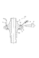
- FIG. 1 shows a laser welding device 3 for welding the contact portion between the annular flange 11 and the ring gear 2 of the differential case 1 and a measuring device 4 for measuring the outer shape of the annular flange 11.
- FIG. 2 shows a cross-sectional view of a contact portion between the annular flange 11 and the ring gear 2.
- the differential gear device 100 includes a differential case 1 and an annular flange 11 standing on the outer peripheral surface of the differential case 1 and a ring gear 2 fixed thereto.
- the differential case 1 is made of spheroidal graphite cast iron, and has a hollow housing portion 12 for housing a drive gear and a pinion gear (not shown) in the center, and a cylindrical shape that supports a drive shaft (not shown) that is connected to the drive gear and drives a wheel.
- the support portions 13 and 14 are formed at the left and right ends of the hollow storage portion 12.
- the ring gear 2 includes a ring-shaped main body portion 21 and tooth portions 22 formed on the outer peripheral side of the main body portion 21. A main body portion 21 of the ring gear 2 is fitted to the outer peripheral surface of the hollow housing portion 12 of the differential case 1.
- the material of the ring gear 2 is chrome molybdenum steel.
- annular flange 11 having a predetermined thickness is erected vertically on the outer peripheral surface of the hollow housing portion 12 of the differential case 1.
- the annular flange 11 has a thickness of about 3 to 5 mm, and one side 111 and the other side 113 are close to each other.
- a flange portion 211 having a height equal to the height of the annular flange 11 of the differential case 1 is formed on the main body portion 21 of the ring gear 2. Therefore, the upper end 112 of the annular flange 11 is flush with the upper end of the flange 211 of the ring gear 2.
- one side surface 111 of the annular flange 11 and the side surface 212 of the flange portion 211 of the ring gear 2 are in contact with each other to form an annular contact portion.
- the length in the radial direction of the contact portion is set to be approximately the same as the welding depth described later.
- a flank 114 (so-called second) is formed on the annular flange 11 on the inner peripheral side of the contact portion.
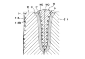
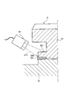
- FIG. 3 is an enlarged cross-sectional view of the lap portion of the weld bead W welded along the contact portion in FIG. 2, FIG. 3A shows a case where no weld crack occurs, and FIG. 3B shows a weld crack (HAZ crack). ) Is shown.
- the laser welding apparatus 3 is disposed above the contact portion between the annular flange 11 and the ring gear main body 21.
- the laser welding device 3 include a carbon dioxide gas laser, a YAG (abbreviation for yttrium aluminum garnet) laser, and a fiber laser.
- the torch 31 of the laser welding apparatus 3 is fixed by a fixture (not shown). Therefore, the differential case 1 and the ring gear 2 are rotated in the direction of arrow R by holding the support portions 13 and 14 of the differential case 1 by a rotating jig (not shown).
- the contact portion between the annular flange 11 and the ring gear main body 21 is melted, and the irradiation of the laser beam 32 is finished when the differential case 1 and the ring gear 2 make one rotation.
- the start and end of irradiation are controlled so that the weld bead W wraps for a certain length.
- the output of the laser beam 32 is controlled.
- the filler 51 is supplied to the upper end surface of the abutting portion from the diagonally upper side by a filler supply device 5 in order to prevent sink marks in the welded portion.
- the filler 51 is usually made of stainless steel, but an optimum material is selected according to the material of the differential case 1 and the material of the ring gear 2.
- laser welding is a high energy density welding method in which coherent light is focused and irradiated at a high density, and therefore the ratio of the penetration width to the penetration depth of the weld bead W is small.
- the penetration depth of the weld bead can be about 6 mm and the penetration width can be about 1.5 to 2 mm. Therefore, the thickness of the annular flange 11 is about 5 to 10 mm.
- the weld bead W does not spread to the other side surface 113 that is not welded. Therefore, the other side surface 113 on which the weld bead W does not spread is maintained flat.
- the molten metal melted by the laser beam 32 is immediately solidified from the base material boundary portion WE toward the weld bead center portion WO after the laser beam 32 passes.
- tensile stress P due to shrinkage is generated and remains. Due to the tensile stress P, the other side surface 113 of the annular flange 11 is pulled in the weld bead direction. Since the place where the weld bead W is wrapped is irradiated with the laser beam 32 twice and the heat input is repeated, the tensile stress P becomes larger than the place where the weld bead W is not wrapped.
- the amount attracted is also increased, and the other side surface 113B of the annular flange 11 corresponding to the location where the weld bead W is wrapped is in contact with the other side surface 113 of the annular flange 11 corresponding to the location where the weld bead W is not wrapped. There will be steps between them.
- a heat affected zone H is formed at the boundary between the weld bead W and the base material.
- the crystal grain size is coarsened by welding heat, and the coarse grain region in the vicinity of the fusion line with the molten metal is generally easily hardened and has low fracture toughness.
- HAZ cracks are likely to occur at places where the toughness is low.
- the HAZ crack starts from the upper end of the weld bead W and extends downward along the heat affected zone H. Further, the HAZ crack occurs along the traveling direction of the weld bead W. Therefore, the HAZ crack boundary surface HC is formed as a gentle curved surface that extends downward along the weld bead W.
- the tensile stress P due to shrinkage is divided by the HAZ crack boundary surface HC. Therefore, when the HAZ crack occurs, the tensile stress P due to shrinkage does not act on the other side surface 113 of the annular flange 11 adjacent to the one side surface 111. As a result, the outer shape of the other side surface 113 of the annular flange 11 is not deformed.
- FIG. 4 is a schematic enlarged view of the welded portion in FIG. 2
- FIG. 4A shows a cross-sectional view of the weld bead W
- FIG. 4B shows a top view of the lap portion L of the weld bead W
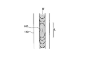
- 5 is a schematic enlarged view of the welded portion when the HAZ crack in FIG. 2 occurs
- FIG. 5A shows a cross-sectional view of the weld bead W
- FIG. 5B is a top view of the lap portion L of the weld bead W. Indicates.
- a measuring device 4 is arranged at a position that is axially controlled with respect to the laser welding device 3.
- the measuring device 4 measures the outer shape of the other side surface 113 of the annular flange 11 after welding by the laser welding device 3.
- the measuring device 4 includes a non-contact type such as an eddy current displacement meter and a contact type such as a dial gauge, which can be employed.
- a compact eddy current displacement meter with high measurement accuracy is installed.
- the sensor head of the eddy current displacement meter is installed in parallel with the other side surface 113 of the annular flange 11.
- the sensor head is disposed close to the upper end side of the annular flange 11. This is because, as the other side surface 113 of the annular flange 11 is closer to the upper end 112, the deformation amount of the outer shape increases as shown in FIG. 4A.
- the measuring device 4 starts measurement simultaneously with the start of welding, and measures data corresponding to the unwrapped portion and the wrapped portion, respectively.
- the other side surface 113 of the annular flange 11 compares the portion corresponding to the lap portion L of the weld bead W with the portion not wrapped.
- the outer shape does not change.
- whether the outer shape of the other side surface 113 of the annular flange 11 corresponds to the lap portion L of the weld bead W and whether or not it is recessed in the weld bead direction compared to the unwrapped portion is determined by welding. It is clearly distinguished by the presence or absence of cracks, especially HAZ cracks.
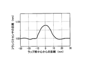
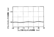
- FIG. 6 is a schematic graph of data obtained by measuring the outer shape of the other side surface 113 in the annular flange 11, and FIG. 6A shows a case where no HAZ crack occurs in the lap portion L of the weld bead W. 6B shows the case where the HAZ crack has occurred in the lap portion L of the weld bead W.
- FIG. 7 the schematic diagram explaining the quality of the lap length in the lap
- the horizontal axis indicates the distance from the center of the lap portion of the weld bead W
- the vertical axis indicates the distance between the other side surface 113 of the annular flange 11 and the sensor head.
- FIG. 6A it can be seen that the outer shape of the other side surface 113 of the annular flange 11 is deformed in the direction away from the sensor head (the direction of the weld bead) within a range of about 20 mm across the center of the lap portion. . In particular, it can be seen that it is recessed by about 50 to 70 ⁇ m in the range of about 10 mm across the center of the wrap portion.
- FIG. 6B it can be seen that the outer shape of the other side surface 113 of the annular flange 11 is hardly deformed.
- the lap allowance of the weld bead W is set to about 10 mm, between the portion corresponding to the lap portion L of the weld bead W and the portion corresponding to the unwrapped weld bead W, about This means that a local difference in deformation amount of 50 to 70 ⁇ m has occurred.
- the length of the wrap length can be determined by measuring the outer shape of the other side surface 113 of the annular flange 11. Specifically, when there is no concave deformation amount, it is determined as NG because the weld bead W is not wrapped. If the amount of concave deformation is substantially equal to the length L1 of the set value, the appropriate wrap length is OK, and if the amount of concave deformation is the length L2 equal to or larger than the set value, it is determined that the wrap is too long and NG. To do.
- the determination step includes the presence or absence of weld cracks, particularly HAZ cracks, and the length of the lap length based on the shape of the portion corresponding to the lap portion of the weld bead among the shapes measured in the measurement step.
- the quality of the welding state can be determined.
- the differential case 1 is provided with the annular flange 11, and the one side surface 111 of the annular flange 11 and the ring gear 2 are connected. Measurement is performed in a welding process for performing butt welding in which the weld bead W wraps along the contact portion, a measuring process for measuring the outer shape of the other side face 113 of the annular flange 11 adjacent to the one side face 111, and a measuring process.
- the coarse grain region near the fusion line is generally easy to harden and its fracture toughness is low.
- HAZ cracks are likely to occur in places with low toughness. Since the HAZ crack occurs along the weld bead W, when the HAZ crack occurs, the outer shape of the other side surface 113 of the annular flange 11 adjacent to the one side surface 111 is not deformed. This is because the tensile stress P due to shrinkage is divided by the HAZ crack and is not transmitted to the other side surface 113.
- the wrap length of the weld bead W is proportional to the length of the outer shape of the other side surface 113 of the annular flange 11 deformed in the welding direction (traveling direction). A step difference from the portion that does not wrap occurs at the boundary of the portion corresponding to. Therefore, if the distance between the steps is measured in the welding direction (traveling direction) and compared with the set value, the quality of the lap length can be easily inspected.
- the outer shape of the other side surface 113 adjacent to the one side surface 111 of the annular flange 11 is measured, and the portion corresponding to the lap portion L of the weld bead W among the measured shapes.
- the quality of the welded state can be inspected based on the shape.
- the case 1 and the vehicle driving force transmission device 100 including the case 1 and the ring gear 2 that is fitted to the outer peripheral surface of the case and transmits the driving force from the driving source It is possible to provide a method for manufacturing the vehicle driving force transmission device 100 that can easily and reliably inspect the quality when the weld bead W wraps and welds the ring gear 2 in-line.
- the welding process is performed by laser welding, and the determination process is performed in the weld bead direction as compared with a position where the shape measured in the measurement process is not lapped at a position corresponding to the lap portion L.
- the determination process is performed in the weld bead direction as compared with a position where the shape measured in the measurement process is not lapped at a position corresponding to the lap portion L.
- the welding process is performed by laser welding, the ratio of the penetration width to the penetration depth of the weld bead W is small. Therefore, even if the thickness of the annular flange 11 is reduced, the other side face close to the one side face 111 is used. The weld bead W does not spread to 113. Therefore, even if the thickness of the annular flange 11 is thin, the other side surface 113 is not melted and remains as it is, so that its outer shape can be easily measured. Further, if the thickness of the annular flange 11 can be reduced, the other side surface 113 is easily affected by the tensile stress P due to the contraction, and the deformation amount of the outer shape appears greatly. Therefore, the portion corresponding to the lap portion L and the other portions And the difference becomes clearer.
- the tensile stress P due to shrinkage causes It can be accurately determined that the other side surface 113 is attracted, and it can be more accurately inspected that a weld crack, particularly a HAZ crack has not occurred.
- the weld crack in particular, the HAZ crack. Since it is possible to immediately and accurately determine the presence or absence of this, it is easier and more reliable. As a result, it is possible to easily and reliably inspect the quality of the case 1 and the ring gear 2 when the weld bead W is wrapped and welded in a simple and reliable manner.
- the annular flange 11 is erected on the outer peripheral surface of the case 1, so if the case 1 is rotated around the axis while the laser welding device 3 and the measuring device 4 are fixed, welding is performed. While measuring. As a result, the quality of the welded state can be inspected in a short time. Therefore, it is possible to more easily and reliably inspect the quality of the case 1 and the ring gear 2 when the weld bead W is wrapped and welded.
- the case 1 is a differential case
- the case 1 and the ring gear 2 can be fixed by butt welding in the differential gear device 100, and the manufacturing cost is reduced as compared with the conventional fixing structure by bolt fastening. Can contribute. Therefore, it is possible to more easily and reliably in-line inspect whether the case 1 and the ring gear 2 are welded by wrapping the weld bead W while reducing the manufacturing cost in the differential gear device 100.
- the manufacturing apparatus of the vehicle driving force transmission device 100 has the following operational effects.
- the present embodiment is an apparatus for manufacturing a vehicle driving force transmission device 100 having a case 1 and a ring gear 2 that is fitted to the outer peripheral surface of the case 1 and transmits a driving force from a driving source. 11, a laser welding apparatus 3 that performs butt welding in which a weld bead W wraps along a contact portion between one side surface 111 of the annular flange 11 and the ring gear 2, and an annular shape adjacent to the one side surface 111.
- the quality of the welding state is determined based on the shape of the measuring device 4 that measures the outer shape of the other side surface 113 of the flange 11 and the shape corresponding to the lap portion L of the weld bead W among the shapes measured in the measurement process. Since the determination device is provided, it is possible to simply and reliably inspect the quality of the welded state at the lap portion L of the weld bead W where welding defects are likely to occur.
- the case 1 and the ring gear 2 are connected to the vehicle driving force transmission device 100 having the case 1 and the ring gear 2 that is fitted to the outer peripheral surface of the case 1 and transmits the driving force from the driving source. Whether the weld bead W is wrapped and welded or not can be inspected easily and reliably in-line.
- this invention is not limited to the said embodiment, Various application is possible.
- butt welding is performed along the contact portion between the ring flange 11 and the ring gear 2 erected on the outer peripheral surface of the differential case 1, but as shown in FIG. 8A.
- butt welding may be performed along the contact portion between the annular flange 61 and the ring gear 7 erected on the outer peripheral surface of the transfer case 6. This is because there is no particular limitation as long as it is a cylindrical case. Therefore, the case referred to in the present invention includes a differential case, a transfer case, and the like. Further, as shown in FIG.
- the annular flange 91 extending from the main body portion of the ring gear 9 along the outer peripheral surface of the transfer case 8 and the outer peripheral portion 82 of the transfer case 8 are butt welded. Good. This is because the fitting portion of the ring gear 9 to the transfer case 8 can be directly welded, so that it is not necessary to newly provide a contact portion between the transfer case 8 and the ring gear 9, and machining can be simplified.
- the ring flange and the annular flange extending from the transfer case may be welded along the outer peripheral surface of the transfer case (including the differential case).
- the measuring device 4 is an eddy current displacement meter, but a two-dimensional laser displacement meter 41 may be used as shown in FIG. This is particularly effective when the annular flange 23 of the ring gear 2 fitted to the case 15 is formed by machining the ring gear main body 21. This is because even when the measuring device cannot be disposed in the groove, measurement can be performed from above or obliquely from above. In this case, since the outer shape of the other side surface 231 of the annular flange 23 and the outer shape of the upper end 232 can be simultaneously measured by the laser beam 411, the deformation amount of the annular flange 23 can be known in more detail. Therefore, the quality of the welded state can be more accurately inspected.
- the laser welding apparatus 3 is used as the welding apparatus, but an electron beam welding apparatus may be used. This is because electron beam welding is also a welding method with high energy density, similar to laser welding.
- the present invention can be used as a manufacturing method and a manufacturing apparatus for a vehicle driving force transmission device such as a differential gear device or a transfer device used in an automobile.
Landscapes
- Engineering & Computer Science (AREA)
- Physics & Mathematics (AREA)
- Optics & Photonics (AREA)
- Mechanical Engineering (AREA)
- Plasma & Fusion (AREA)
- General Engineering & Computer Science (AREA)
- Quality & Reliability (AREA)
- General Physics & Mathematics (AREA)
- Chemical & Material Sciences (AREA)
- Inorganic Chemistry (AREA)
- Retarders (AREA)
- Laser Beam Processing (AREA)
- Welding Or Cutting Using Electron Beams (AREA)
- Gears, Cams (AREA)
Abstract
Description
まず、デフケースとリングギヤとの当接部の構造から説明する。図1に、デフケース1の環状フランジ11とリングギヤ2との当接部を溶接するレーザー溶接装置3と、環状フランジ11の外形形状を計測する計測装置4を示す。図2に、環状フランジ11とリングギヤ2との当接部の断面図を示す。
次に、当接部に沿って突合せ溶接する溶接工程について説明する。図3は、図2における当接部に沿って溶接した溶接ビードWのラップ部における拡大断面図であって、図3Aは溶接割れが生じていない場合を示し、図3Bは溶接割れ(HAZ割れ)が生じている場合を示す。
次に、環状フランジ11の他方の側面113の外形形状を計測する計測工程について説明する。図4は、図2における溶接部の模式的拡大図であって、図4Aは溶接ビードWの断面図を示し、図4Bは溶接ビードWのラップ部Lにおける上面図を示す。図5は、図2におけるHAZ割れが生じたときの溶接部の模式的拡大図であって、図5Aは溶接ビードWの断面図を示し、図5Bは溶接ビードWのラップ部Lにおける上面図を示す。
次に、判定工程について説明する。図6は、環状フランジ11にける他方の側面113の外形形状を計測したデータの模式的グラフであって、図6Aは溶接ビードWのラップ部LにおいてHAZ割れが生じていないときを示し、図6Bは溶接ビードWのラップ部LにおいてHAZ割れが生じているときを示す。図7に、溶接ビードWのラップ部Lにおけるラップ長さの良否を説明する模式図を示す。
以上、詳細に説明したように、本実施形態に係る車両用駆動力伝達装置100の製造方法は、デフケース1に環状フランジ11を設けて、該環状フランジ11の一方の側面111とリングギヤ2との当接部に沿って、溶接ビードWがラップする突合せ溶接を行う溶接工程と、一方の側面111と近接する環状フランジ11の他方の側面113の外形形状を計測する計測工程と、計測工程で計測した形状の内、溶接ビードWのラップ部Lに対応する箇所113、113Bの形状に基づいて溶接状態の良否を判定する判定工程とを備えるので、溶接不良の生じやすい溶接ビードWのラップ部Lにおける溶接状態の良否を簡単かつ確実に全数検査をすることができる。
(1)例えば、上記実施形態では、図1に示すように、デフケース1の外周面に立設した環状フランジ11とリングギヤ2との当接部に沿って突合せ溶接したが、図8Aに示すように、トランスファ装置101において、トランスファケース6の外周面に立設した環状フランジ61とリングギヤ7との当接部に沿って突合せ溶接してもよい。筒状のケースであれば、特に限定されるものではないからである。したがって、本発明で言うケースとは、デフケース、トランスファケース等を含むものとする。また、図8Bに示すように、トランスファ装置102において、トランスファケース8の外周面に沿ってリングギヤ9の本体部から延設した環状フランジ91とトランスファケース8の外周部82とを突合せ溶接してもよい。リングギヤ9のトランスファケース8への嵌合部を直接溶接できるので、トランスファケース8とリングギヤ9との当接部を新たに設ける必要がなく、機械加工を簡略化できるからである。なお、トランスファケース(デフケースを含む)の外周面に沿ってトランスファケース(デフケースを含む)から延設した環状フランジとリングギヤとを溶接してもよいことは、勿論である。
2 リングギヤ
3 レーザー溶接装置
4 計測装置
5 フィラー供給装置
6 トランスファケース
7 リングギヤ
8 トランスファケース
9 リングギヤ
11 環状フランジ
12 中空収納部
21 リングギヤの本体部
22 リングギヤの歯部
31 トーチ
32 レーザービーム
51 フィラー
100 デフギヤ装置
101 トランスファ装置
102 トランスファ装置
111 環状フランジの一方の側面
112 環状フランジの上端
113 環状フランジの他方の側面
211 リングギヤの鍔部
212 リングギヤの鍔部側面
H 熱影響部
P 引張り応力
L ラップ部
W 溶接ビード
WE 母材境界部
WO 溶接ビード中心部
HC HAZ割れ境界面
Claims (6)
- ケースと該ケースの外周面に嵌合されて駆動源からの駆動力を伝達するリングギヤとを有する車両用駆動力伝達装置の製造方法において、
前記ケース又は前記リングギヤのいずれか一方に環状フランジを設けて、該環状フランジの一方の側面と前記ケース又は前記リングギヤとの当接部に沿って、溶接ビードがラップする突合せ溶接を行う溶接工程と、
前記一方の側面と近接する前記環状フランジの他方の側面の外形形状を計測する計測工程と、
前記計測工程で計測した形状の内、前記溶接ビードのラップ部に対応する箇所の形状に基づいて溶接状態の良否を判定する判定工程とを備えることを特徴とする車両用駆動力伝達装置の製造方法。 - 請求項1に記載された車両用駆動力伝達装置の製造方法において、
前記溶接工程は、レーザー溶接により行うこと、
前記判定工程は、前記計測工程で計測した形状が前記ラップ部に対応する箇所でラップしていない箇所に比較して溶接ビード方向に凹んでいるときには、溶接割れが生じていないと判定することを特徴とする車両用駆動力伝達装置の製造方法。 - 請求項1又は請求項2に記載された車両用駆動力伝達装置の製造方法において、
前記環状フランジは、前記ケースの外周面に立設したことを特徴とする車両用駆動力伝達装置の製造方法。 - 請求項1又は請求項2に記載された車両用駆動力伝達装置の製造方法において、
前記環状フランジは、前記ケースの外周面に沿って前記リングギヤの本体部から延設したことを特徴とする車両用駆動力伝達装置の製造方法。 - 請求項3又は請求項4に記載された車両用駆動力伝達装置の製造方法において、
前記ケースは、デファレンシャルケース又はトランスファケースであることを特徴とする車両用駆動力伝達装置の製造方法。 - ケースと該ケースの外周面に嵌合されて駆動源からの駆動力を伝達するリングギヤとを有する車両用駆動力伝達装置の製造装置において、
前記ケース又は前記リングギヤのいずれか一方に環状フランジを設けて、該環状フランジの一方の側面と前記ケース又は前記リングギヤとの当接部に沿って、溶接ビードがラップする突合せ溶接を行う溶接装置と、
前記一方の側面と近接する前記環状フランジの他方の側面の外形形状を計測する計測装置と、
前記計測工程で計測した形状の内、前記溶接ビードのラップ部に対応する箇所の形状に基づいて溶接状態の良否を判定する判定装置とを備えることを特徴とする車両用駆動力伝達装置の製造装置。
Priority Applications (5)
| Application Number | Priority Date | Filing Date | Title |
|---|---|---|---|
| JP2012514247A JP5252126B2 (ja) | 2011-04-18 | 2011-04-18 | 車両用駆動力伝達装置の製造方法及び製造装置 |
| US14/112,363 US9120184B2 (en) | 2011-04-18 | 2011-04-18 | Method and apparatus for manufacturing vehicle power transmission device |
| EP11863740.4A EP2700847B1 (en) | 2011-04-18 | 2011-04-18 | Method and apparatus for manufacturing vehicle power transmission device |
| CN201180070267.2A CN103492764B (zh) | 2011-04-18 | 2011-04-18 | 车辆用驱动力传递装置的制造方法及制造装置 |
| PCT/JP2011/059491 WO2012143986A1 (ja) | 2011-04-18 | 2011-04-18 | 車両用駆動力伝達装置の製造方法及び製造装置 |
Applications Claiming Priority (1)
| Application Number | Priority Date | Filing Date | Title |
|---|---|---|---|
| PCT/JP2011/059491 WO2012143986A1 (ja) | 2011-04-18 | 2011-04-18 | 車両用駆動力伝達装置の製造方法及び製造装置 |
Publications (1)
| Publication Number | Publication Date |
|---|---|
| WO2012143986A1 true WO2012143986A1 (ja) | 2012-10-26 |
Family
ID=47041140
Family Applications (1)
| Application Number | Title | Priority Date | Filing Date |
|---|---|---|---|
| PCT/JP2011/059491 Ceased WO2012143986A1 (ja) | 2011-04-18 | 2011-04-18 | 車両用駆動力伝達装置の製造方法及び製造装置 |
Country Status (5)
| Country | Link |
|---|---|
| US (1) | US9120184B2 (ja) |
| EP (1) | EP2700847B1 (ja) |
| JP (1) | JP5252126B2 (ja) |
| CN (1) | CN103492764B (ja) |
| WO (1) | WO2012143986A1 (ja) |
Cited By (5)
| Publication number | Priority date | Publication date | Assignee | Title |
|---|---|---|---|---|
| CN104074861A (zh) * | 2013-03-25 | 2014-10-01 | 联创汽车电子有限公司 | 摇臂机构及其制造方法 |
| JP2016016412A (ja) * | 2014-07-04 | 2016-02-01 | マツダ株式会社 | 金属部材の溶接良否判定方法及び装置 |
| DE102017006417A1 (de) | 2016-08-08 | 2018-02-08 | Subaru Corporation | Verfahren zur Herstellung einer Differenzialvorrichtung und Differenzialvorrichtung |
| JP2022165159A (ja) * | 2021-04-19 | 2022-10-31 | マツダ株式会社 | レーザ溶接方法 |
| CN115805370A (zh) * | 2022-12-30 | 2023-03-17 | 中国重汽集团济南动力有限公司 | 一体式商用车轮间差速器焊接制造工艺 |
Families Citing this family (14)
| Publication number | Priority date | Publication date | Assignee | Title |
|---|---|---|---|---|
| JP5823278B2 (ja) * | 2011-12-13 | 2015-11-25 | 株式会社東芝 | 溶接ビード整形装置およびその整形方法 |
| JP6730927B2 (ja) * | 2014-01-24 | 2020-07-29 | エレクトリック パワー リサーチ インスチテュート インコーポレイテッド | 段付き設計の溶接継手用作製物 |
| JP6437758B2 (ja) * | 2014-08-12 | 2018-12-12 | Ntn株式会社 | 等速自在継手の接合タイプ外側継手部材の検査装置 |
| DE102015000928B3 (de) * | 2015-01-28 | 2016-07-21 | Thyssenkrupp Ag | Vorrichtung zur Einbringung eines Hilfsdrehmoments in eine Lenkwelle einer elektromechanischen Hilfskraftlenkung |
| JP6521050B2 (ja) * | 2015-02-16 | 2019-05-29 | 株式会社タダノ | 液圧シリンダ、シリンダ装置、作業車両、及び液圧シリンダ製造方法 |
| WO2017017805A1 (ja) * | 2015-07-29 | 2017-02-02 | Gkn ドライブライン ジャパン株式会社 | デファレンシャルケース |
| US20170152930A1 (en) * | 2015-11-30 | 2017-06-01 | Ford Global Technologies, Llc | Precisely aligned, friction welded spiral bevel or hypoid ring gear and differential case assembly |
| US10781908B2 (en) * | 2017-12-11 | 2020-09-22 | Gkn Automotive Limited | Driveline components with weld vent |
| EP3815836B1 (en) * | 2018-06-27 | 2023-11-22 | SMC Corporation | Butt welded joint of steel material and method for manufacturing same |
| US11306784B2 (en) | 2018-10-11 | 2022-04-19 | Transform Automotive Llc | Vehicle drivetrain assembly and method for making the assembly |
| US11213917B2 (en) * | 2018-11-13 | 2022-01-04 | GM Global Technology Operations LLC | Fusion welding of ferrous alloy component parts using low carbon steel band |
| DE102019201704A1 (de) * | 2019-02-11 | 2020-08-13 | Robert Bosch Gmbh | Verfahren zum Laserschweißen von Werkstücken |
| US11561204B2 (en) * | 2019-08-28 | 2023-01-24 | Kabushiki Kaisha Toshiba | Display control system, inspection control system, display control method, and storage medium |
| US12540663B1 (en) * | 2025-01-02 | 2026-02-03 | GM Global Technology Operations LLC | Vehicle differential and welding |
Citations (7)
| Publication number | Priority date | Publication date | Assignee | Title |
|---|---|---|---|---|
| JPH11151587A (ja) * | 1997-11-18 | 1999-06-08 | Canon Inc | 円筒部材の溶接方法及び円筒体 |
| JP2000039308A (ja) | 1998-07-21 | 2000-02-08 | Natl Res Inst For Metals | 溶接部の動的ひずみ測定方法 |
| JP2004009068A (ja) * | 2002-06-04 | 2004-01-15 | Nippon Steel Corp | ハイドロフォーム加工性に優れたテーラード鋼管及びその製造方法 |
| JP2006275536A (ja) * | 2005-03-28 | 2006-10-12 | Topy Ind Ltd | 溶接部の検査装置 |
| JP2010131629A (ja) | 2008-12-04 | 2010-06-17 | Toshiba Corp | 溶接構造物の変形監視装置及び方法 |
| JP2010174924A (ja) * | 2009-01-27 | 2010-08-12 | Toyota Motor Corp | ディファレンシャル装置 |
| JP2010180976A (ja) * | 2009-02-06 | 2010-08-19 | Gkn Driveline Japan Ltd | デファレンシャル装置 |
Family Cites Families (10)
| Publication number | Priority date | Publication date | Assignee | Title |
|---|---|---|---|---|
| JPS632519A (ja) * | 1986-06-23 | 1988-01-07 | Toyo Seikan Kaisha Ltd | チユ−ブの製造方法及び装置 |
| DE4317073A1 (de) * | 1993-05-21 | 1994-11-24 | Porsche Ag | Differentialgehäuse für den Achsantrieb eines Kraftfahrzeuges |
| EP0916443A1 (en) | 1997-11-18 | 1999-05-19 | Canon Kabushiki Kaisha | Rotating member and rotating shaft member, fixing roller, cylindrical member, and cylinder of image forming apparatus, cylindrical member welding method, rotating shaft member manufacturing method, and method of manufacturing developing sleeve of image forming apparatus |
| JP2000111530A (ja) | 1998-10-02 | 2000-04-21 | Technological Res Assoc Of Mega-Float | 溶接部亀裂探傷方法および装置 |
| JP2004184350A (ja) | 2002-12-06 | 2004-07-02 | Komai Tekko Inc | 鋼材溶接部に於けるアンダーカット測定装置 |
| CN2667241Y (zh) * | 2003-12-16 | 2004-12-29 | 中国三江航天工业集团公司 | 牙嵌自由轮式差速器 |
| JP2007524054A (ja) * | 2004-02-24 | 2007-08-23 | ザ ティムケン カンパニー | 温度補償型差動装置 |
| JP4530750B2 (ja) * | 2004-07-21 | 2010-08-25 | 株式会社ユタカ技研 | ロックアップクラッチ付き流体伝動装置 |
| JP5072099B2 (ja) * | 2008-02-27 | 2012-11-14 | 武蔵精密工業株式会社 | ディファレンシャル装置 |
| JP4725660B2 (ja) | 2009-03-06 | 2011-07-13 | トヨタ自動車株式会社 | 差動歯車装置 |
-
2011
- 2011-04-18 CN CN201180070267.2A patent/CN103492764B/zh not_active Expired - Fee Related
- 2011-04-18 US US14/112,363 patent/US9120184B2/en not_active Expired - Fee Related
- 2011-04-18 WO PCT/JP2011/059491 patent/WO2012143986A1/ja not_active Ceased
- 2011-04-18 JP JP2012514247A patent/JP5252126B2/ja not_active Expired - Fee Related
- 2011-04-18 EP EP11863740.4A patent/EP2700847B1/en not_active Not-in-force
Patent Citations (7)
| Publication number | Priority date | Publication date | Assignee | Title |
|---|---|---|---|---|
| JPH11151587A (ja) * | 1997-11-18 | 1999-06-08 | Canon Inc | 円筒部材の溶接方法及び円筒体 |
| JP2000039308A (ja) | 1998-07-21 | 2000-02-08 | Natl Res Inst For Metals | 溶接部の動的ひずみ測定方法 |
| JP2004009068A (ja) * | 2002-06-04 | 2004-01-15 | Nippon Steel Corp | ハイドロフォーム加工性に優れたテーラード鋼管及びその製造方法 |
| JP2006275536A (ja) * | 2005-03-28 | 2006-10-12 | Topy Ind Ltd | 溶接部の検査装置 |
| JP2010131629A (ja) | 2008-12-04 | 2010-06-17 | Toshiba Corp | 溶接構造物の変形監視装置及び方法 |
| JP2010174924A (ja) * | 2009-01-27 | 2010-08-12 | Toyota Motor Corp | ディファレンシャル装置 |
| JP2010180976A (ja) * | 2009-02-06 | 2010-08-19 | Gkn Driveline Japan Ltd | デファレンシャル装置 |
Non-Patent Citations (1)
| Title |
|---|
| See also references of EP2700847A4 |
Cited By (8)
| Publication number | Priority date | Publication date | Assignee | Title |
|---|---|---|---|---|
| CN104074861A (zh) * | 2013-03-25 | 2014-10-01 | 联创汽车电子有限公司 | 摇臂机构及其制造方法 |
| JP2016016412A (ja) * | 2014-07-04 | 2016-02-01 | マツダ株式会社 | 金属部材の溶接良否判定方法及び装置 |
| DE102017006417A1 (de) | 2016-08-08 | 2018-02-08 | Subaru Corporation | Verfahren zur Herstellung einer Differenzialvorrichtung und Differenzialvorrichtung |
| US10539216B2 (en) | 2016-08-08 | 2020-01-21 | Subaru Corporation | Method for manufacturing differential device and differential device |
| DE102017006417B4 (de) * | 2016-08-08 | 2021-01-28 | Subaru Corporation | Verfahren zur Herstellung einer Differenzialvorrichtung und Differenzialvorrichtung |
| JP2022165159A (ja) * | 2021-04-19 | 2022-10-31 | マツダ株式会社 | レーザ溶接方法 |
| JP7613230B2 (ja) | 2021-04-19 | 2025-01-15 | マツダ株式会社 | レーザ溶接方法 |
| CN115805370A (zh) * | 2022-12-30 | 2023-03-17 | 中国重汽集团济南动力有限公司 | 一体式商用车轮间差速器焊接制造工艺 |
Also Published As
| Publication number | Publication date |
|---|---|
| EP2700847B1 (en) | 2017-10-11 |
| CN103492764A (zh) | 2014-01-01 |
| EP2700847A4 (en) | 2015-11-11 |
| US9120184B2 (en) | 2015-09-01 |
| CN103492764B (zh) | 2016-03-02 |
| EP2700847A1 (en) | 2014-02-26 |
| JP5252126B2 (ja) | 2013-07-31 |
| US20140042208A1 (en) | 2014-02-13 |
| JPWO2012143986A1 (ja) | 2014-07-28 |
Similar Documents
| Publication | Publication Date | Title |
|---|---|---|
| JP5252126B2 (ja) | 車両用駆動力伝達装置の製造方法及び製造装置 | |
| KR101447393B1 (ko) | 용접 구조 | |
| JP6437758B2 (ja) | 等速自在継手の接合タイプ外側継手部材の検査装置 | |
| JP2012006078A (ja) | 溶接システムおよび溶接方法 | |
| EP2716400B1 (en) | Welded joint structure and weld quality detection method | |
| US20200363376A1 (en) | Process for forming and quality proofing a friction stir welded plate | |
| CN107971625A (zh) | 一种调整惯性摩擦焊机主轴侧与尾座侧同轴度的专用方法 | |
| JP6385763B2 (ja) | レーザ溶接装置及びレーザ溶接方法 | |
| US8359925B2 (en) | Rotor disk weld inspection method and arrangement | |
| JP5818009B2 (ja) | 溶接部硬度評価方法 | |
| RU2537418C2 (ru) | Способ ремонта валов | |
| JP2020071180A (ja) | デファレンシャルギヤユニットの超音波検査方法 | |
| JP7226058B2 (ja) | レーザ溶接方法及びレーザ溶接装置 | |
| JP2014128821A (ja) | 金属管の溶接による曲がり変形低減方法及びそれに用いる曲がり変形低減装置 | |
| CN113235461B (zh) | 一种悬索桥索夹耳孔和箱梁耳孔的修复方法 | |
| JP2017087217A (ja) | 溶接方法及び溶接部検査方法 | |
| JP3247239B2 (ja) | 非対称のど厚を有する裏波溶接ビードルート止端部の折れ込み状欠陥の防止方法 | |
| JP2016016412A (ja) | 金属部材の溶接良否判定方法及び装置 | |
| Tang et al. | Fatigue life improvement of fillet welded joints by friction stir processing | |
| Ambroziak et al. | Properties of weld overlays on regenerated wheel hub of a mining vehicle | |
| CN117428361A (zh) | 一种提高核级承压设备的结构模块构件焊缝质量的方法 | |
| CN119618794A (zh) | 一种焊接质量测试方法、冲击试样的制备方法和冲击试样 | |
| JP2017078651A (ja) | バルブシート用肉盛層の品質判定方法 |
Legal Events
| Date | Code | Title | Description |
|---|---|---|---|
| ENP | Entry into the national phase |
Ref document number: 2012514247 Country of ref document: JP Kind code of ref document: A |
|
| 121 | Ep: the epo has been informed by wipo that ep was designated in this application |
Ref document number: 11863740 Country of ref document: EP Kind code of ref document: A1 |
|
| REEP | Request for entry into the european phase |
Ref document number: 2011863740 Country of ref document: EP |
|
| WWE | Wipo information: entry into national phase |
Ref document number: 14112363 Country of ref document: US Ref document number: 2011863740 Country of ref document: EP |
|
| NENP | Non-entry into the national phase |
Ref country code: DE |