WO2012144061A1 - 車両および車両用制御方法 - Google Patents
車両および車両用制御方法 Download PDFInfo
- Publication number
- WO2012144061A1 WO2012144061A1 PCT/JP2011/059903 JP2011059903W WO2012144061A1 WO 2012144061 A1 WO2012144061 A1 WO 2012144061A1 JP 2011059903 W JP2011059903 W JP 2011059903W WO 2012144061 A1 WO2012144061 A1 WO 2012144061A1
- Authority
- WO
- WIPO (PCT)
- Prior art keywords
- vehicle
- value
- amount
- soc
- pchg
- Prior art date
- Legal status (The legal status is an assumption and is not a legal conclusion. Google has not performed a legal analysis and makes no representation as to the accuracy of the status listed.)
- Ceased
Links
Images



Classifications
-
- B—PERFORMING OPERATIONS; TRANSPORTING
- B60—VEHICLES IN GENERAL
- B60L—PROPULSION OF ELECTRICALLY-PROPELLED VEHICLES; SUPPLYING ELECTRIC POWER FOR AUXILIARY EQUIPMENT OF ELECTRICALLY-PROPELLED VEHICLES; ELECTRODYNAMIC BRAKE SYSTEMS FOR VEHICLES IN GENERAL; MAGNETIC SUSPENSION OR LEVITATION FOR VEHICLES; MONITORING OPERATING VARIABLES OF ELECTRICALLY-PROPELLED VEHICLES; ELECTRIC SAFETY DEVICES FOR ELECTRICALLY-PROPELLED VEHICLES
- B60L58/00—Methods or circuit arrangements for monitoring or controlling batteries or fuel cells, specially adapted for electric vehicles
- B60L58/10—Methods or circuit arrangements for monitoring or controlling batteries or fuel cells, specially adapted for electric vehicles for monitoring or controlling batteries
- B60L58/12—Methods or circuit arrangements for monitoring or controlling batteries or fuel cells, specially adapted for electric vehicles for monitoring or controlling batteries responding to state of charge [SoC]
- B60L58/13—Maintaining the SoC within a determined range
-
- B—PERFORMING OPERATIONS; TRANSPORTING
- B60—VEHICLES IN GENERAL
- B60K—ARRANGEMENT OR MOUNTING OF PROPULSION UNITS OR OF TRANSMISSIONS IN VEHICLES; ARRANGEMENT OR MOUNTING OF PLURAL DIVERSE PRIME-MOVERS IN VEHICLES; AUXILIARY DRIVES FOR VEHICLES; INSTRUMENTATION OR DASHBOARDS FOR VEHICLES; ARRANGEMENTS IN CONNECTION WITH COOLING, AIR INTAKE, GAS EXHAUST OR FUEL SUPPLY OF PROPULSION UNITS IN VEHICLES
- B60K6/00—Arrangement or mounting of plural diverse prime-movers for mutual or common propulsion, e.g. hybrid propulsion systems comprising electric motors and internal combustion engines
- B60K6/20—Arrangement or mounting of plural diverse prime-movers for mutual or common propulsion, e.g. hybrid propulsion systems comprising electric motors and internal combustion engines the prime-movers consisting of electric motors and internal combustion engines, e.g. HEVs
- B60K6/42—Arrangement or mounting of plural diverse prime-movers for mutual or common propulsion, e.g. hybrid propulsion systems comprising electric motors and internal combustion engines the prime-movers consisting of electric motors and internal combustion engines, e.g. HEVs characterised by the architecture of the hybrid electric vehicle
- B60K6/44—Series-parallel type
- B60K6/445—Differential gearing distribution type
-
- B—PERFORMING OPERATIONS; TRANSPORTING
- B60—VEHICLES IN GENERAL
- B60L—PROPULSION OF ELECTRICALLY-PROPELLED VEHICLES; SUPPLYING ELECTRIC POWER FOR AUXILIARY EQUIPMENT OF ELECTRICALLY-PROPELLED VEHICLES; ELECTRODYNAMIC BRAKE SYSTEMS FOR VEHICLES IN GENERAL; MAGNETIC SUSPENSION OR LEVITATION FOR VEHICLES; MONITORING OPERATING VARIABLES OF ELECTRICALLY-PROPELLED VEHICLES; ELECTRIC SAFETY DEVICES FOR ELECTRICALLY-PROPELLED VEHICLES
- B60L50/00—Electric propulsion with power supplied within the vehicle
- B60L50/10—Electric propulsion with power supplied within the vehicle using propulsion power supplied by engine-driven generators, e.g. generators driven by combustion engines
- B60L50/16—Electric propulsion with power supplied within the vehicle using propulsion power supplied by engine-driven generators, e.g. generators driven by combustion engines with provision for separate direct mechanical propulsion
-
- B—PERFORMING OPERATIONS; TRANSPORTING
- B60—VEHICLES IN GENERAL
- B60L—PROPULSION OF ELECTRICALLY-PROPELLED VEHICLES; SUPPLYING ELECTRIC POWER FOR AUXILIARY EQUIPMENT OF ELECTRICALLY-PROPELLED VEHICLES; ELECTRODYNAMIC BRAKE SYSTEMS FOR VEHICLES IN GENERAL; MAGNETIC SUSPENSION OR LEVITATION FOR VEHICLES; MONITORING OPERATING VARIABLES OF ELECTRICALLY-PROPELLED VEHICLES; ELECTRIC SAFETY DEVICES FOR ELECTRICALLY-PROPELLED VEHICLES
- B60L50/00—Electric propulsion with power supplied within the vehicle
- B60L50/50—Electric propulsion with power supplied within the vehicle using propulsion power supplied by batteries or fuel cells
- B60L50/60—Electric propulsion with power supplied within the vehicle using propulsion power supplied by batteries or fuel cells using power supplied by batteries
- B60L50/61—Electric propulsion with power supplied within the vehicle using propulsion power supplied by batteries or fuel cells using power supplied by batteries by batteries charged by engine-driven generators, e.g. series hybrid electric vehicles
-
- B—PERFORMING OPERATIONS; TRANSPORTING
- B60—VEHICLES IN GENERAL
- B60L—PROPULSION OF ELECTRICALLY-PROPELLED VEHICLES; SUPPLYING ELECTRIC POWER FOR AUXILIARY EQUIPMENT OF ELECTRICALLY-PROPELLED VEHICLES; ELECTRODYNAMIC BRAKE SYSTEMS FOR VEHICLES IN GENERAL; MAGNETIC SUSPENSION OR LEVITATION FOR VEHICLES; MONITORING OPERATING VARIABLES OF ELECTRICALLY-PROPELLED VEHICLES; ELECTRIC SAFETY DEVICES FOR ELECTRICALLY-PROPELLED VEHICLES
- B60L58/00—Methods or circuit arrangements for monitoring or controlling batteries or fuel cells, specially adapted for electric vehicles
- B60L58/10—Methods or circuit arrangements for monitoring or controlling batteries or fuel cells, specially adapted for electric vehicles for monitoring or controlling batteries
- B60L58/12—Methods or circuit arrangements for monitoring or controlling batteries or fuel cells, specially adapted for electric vehicles for monitoring or controlling batteries responding to state of charge [SoC]
- B60L58/15—Preventing overcharging
-
- B—PERFORMING OPERATIONS; TRANSPORTING
- B60—VEHICLES IN GENERAL
- B60W—CONJOINT CONTROL OF VEHICLE SUB-UNITS OF DIFFERENT TYPE OR DIFFERENT FUNCTION; CONTROL SYSTEMS SPECIALLY ADAPTED FOR HYBRID VEHICLES; ROAD VEHICLE DRIVE CONTROL SYSTEMS FOR PURPOSES NOT RELATED TO THE CONTROL OF A PARTICULAR SUB-UNIT
- B60W10/00—Conjoint control of vehicle sub-units of different type or different function
- B60W10/04—Conjoint control of vehicle sub-units of different type or different function including control of propulsion units
- B60W10/06—Conjoint control of vehicle sub-units of different type or different function including control of propulsion units including control of combustion engines
-
- B—PERFORMING OPERATIONS; TRANSPORTING
- B60—VEHICLES IN GENERAL
- B60W—CONJOINT CONTROL OF VEHICLE SUB-UNITS OF DIFFERENT TYPE OR DIFFERENT FUNCTION; CONTROL SYSTEMS SPECIALLY ADAPTED FOR HYBRID VEHICLES; ROAD VEHICLE DRIVE CONTROL SYSTEMS FOR PURPOSES NOT RELATED TO THE CONTROL OF A PARTICULAR SUB-UNIT
- B60W10/00—Conjoint control of vehicle sub-units of different type or different function
- B60W10/04—Conjoint control of vehicle sub-units of different type or different function including control of propulsion units
- B60W10/08—Conjoint control of vehicle sub-units of different type or different function including control of propulsion units including control of electric propulsion units, e.g. motors or generators
-
- B—PERFORMING OPERATIONS; TRANSPORTING
- B60—VEHICLES IN GENERAL
- B60W—CONJOINT CONTROL OF VEHICLE SUB-UNITS OF DIFFERENT TYPE OR DIFFERENT FUNCTION; CONTROL SYSTEMS SPECIALLY ADAPTED FOR HYBRID VEHICLES; ROAD VEHICLE DRIVE CONTROL SYSTEMS FOR PURPOSES NOT RELATED TO THE CONTROL OF A PARTICULAR SUB-UNIT
- B60W10/00—Conjoint control of vehicle sub-units of different type or different function
- B60W10/24—Conjoint control of vehicle sub-units of different type or different function including control of energy storage means
- B60W10/26—Conjoint control of vehicle sub-units of different type or different function including control of energy storage means for electrical energy, e.g. batteries or capacitors
-
- B—PERFORMING OPERATIONS; TRANSPORTING
- B60—VEHICLES IN GENERAL
- B60W—CONJOINT CONTROL OF VEHICLE SUB-UNITS OF DIFFERENT TYPE OR DIFFERENT FUNCTION; CONTROL SYSTEMS SPECIALLY ADAPTED FOR HYBRID VEHICLES; ROAD VEHICLE DRIVE CONTROL SYSTEMS FOR PURPOSES NOT RELATED TO THE CONTROL OF A PARTICULAR SUB-UNIT
- B60W20/00—Control systems specially adapted for hybrid vehicles
- B60W20/10—Controlling the power contribution of each of the prime movers to meet required power demand
- B60W20/13—Controlling the power contribution of each of the prime movers to meet required power demand in order to stay within battery power input or output limits; in order to prevent overcharging or battery depletion
-
- B—PERFORMING OPERATIONS; TRANSPORTING
- B60—VEHICLES IN GENERAL
- B60L—PROPULSION OF ELECTRICALLY-PROPELLED VEHICLES; SUPPLYING ELECTRIC POWER FOR AUXILIARY EQUIPMENT OF ELECTRICALLY-PROPELLED VEHICLES; ELECTRODYNAMIC BRAKE SYSTEMS FOR VEHICLES IN GENERAL; MAGNETIC SUSPENSION OR LEVITATION FOR VEHICLES; MONITORING OPERATING VARIABLES OF ELECTRICALLY-PROPELLED VEHICLES; ELECTRIC SAFETY DEVICES FOR ELECTRICALLY-PROPELLED VEHICLES
- B60L2210/00—Converter types
- B60L2210/10—DC to DC converters
- B60L2210/14—Boost converters
-
- B—PERFORMING OPERATIONS; TRANSPORTING
- B60—VEHICLES IN GENERAL
- B60L—PROPULSION OF ELECTRICALLY-PROPELLED VEHICLES; SUPPLYING ELECTRIC POWER FOR AUXILIARY EQUIPMENT OF ELECTRICALLY-PROPELLED VEHICLES; ELECTRODYNAMIC BRAKE SYSTEMS FOR VEHICLES IN GENERAL; MAGNETIC SUSPENSION OR LEVITATION FOR VEHICLES; MONITORING OPERATING VARIABLES OF ELECTRICALLY-PROPELLED VEHICLES; ELECTRIC SAFETY DEVICES FOR ELECTRICALLY-PROPELLED VEHICLES
- B60L2210/00—Converter types
- B60L2210/40—DC to AC converters
-
- B—PERFORMING OPERATIONS; TRANSPORTING
- B60—VEHICLES IN GENERAL
- B60L—PROPULSION OF ELECTRICALLY-PROPELLED VEHICLES; SUPPLYING ELECTRIC POWER FOR AUXILIARY EQUIPMENT OF ELECTRICALLY-PROPELLED VEHICLES; ELECTRODYNAMIC BRAKE SYSTEMS FOR VEHICLES IN GENERAL; MAGNETIC SUSPENSION OR LEVITATION FOR VEHICLES; MONITORING OPERATING VARIABLES OF ELECTRICALLY-PROPELLED VEHICLES; ELECTRIC SAFETY DEVICES FOR ELECTRICALLY-PROPELLED VEHICLES
- B60L2240/00—Control parameters of input or output; Target parameters
- B60L2240/10—Vehicle control parameters
- B60L2240/12—Speed
-
- B—PERFORMING OPERATIONS; TRANSPORTING
- B60—VEHICLES IN GENERAL
- B60L—PROPULSION OF ELECTRICALLY-PROPELLED VEHICLES; SUPPLYING ELECTRIC POWER FOR AUXILIARY EQUIPMENT OF ELECTRICALLY-PROPELLED VEHICLES; ELECTRODYNAMIC BRAKE SYSTEMS FOR VEHICLES IN GENERAL; MAGNETIC SUSPENSION OR LEVITATION FOR VEHICLES; MONITORING OPERATING VARIABLES OF ELECTRICALLY-PROPELLED VEHICLES; ELECTRIC SAFETY DEVICES FOR ELECTRICALLY-PROPELLED VEHICLES
- B60L2240/00—Control parameters of input or output; Target parameters
- B60L2240/40—Drive Train control parameters
- B60L2240/54—Drive Train control parameters related to batteries
- B60L2240/547—Voltage
-
- B—PERFORMING OPERATIONS; TRANSPORTING
- B60—VEHICLES IN GENERAL
- B60L—PROPULSION OF ELECTRICALLY-PROPELLED VEHICLES; SUPPLYING ELECTRIC POWER FOR AUXILIARY EQUIPMENT OF ELECTRICALLY-PROPELLED VEHICLES; ELECTRODYNAMIC BRAKE SYSTEMS FOR VEHICLES IN GENERAL; MAGNETIC SUSPENSION OR LEVITATION FOR VEHICLES; MONITORING OPERATING VARIABLES OF ELECTRICALLY-PROPELLED VEHICLES; ELECTRIC SAFETY DEVICES FOR ELECTRICALLY-PROPELLED VEHICLES
- B60L2240/00—Control parameters of input or output; Target parameters
- B60L2240/40—Drive Train control parameters
- B60L2240/54—Drive Train control parameters related to batteries
- B60L2240/549—Current
-
- B—PERFORMING OPERATIONS; TRANSPORTING
- B60—VEHICLES IN GENERAL
- B60L—PROPULSION OF ELECTRICALLY-PROPELLED VEHICLES; SUPPLYING ELECTRIC POWER FOR AUXILIARY EQUIPMENT OF ELECTRICALLY-PROPELLED VEHICLES; ELECTRODYNAMIC BRAKE SYSTEMS FOR VEHICLES IN GENERAL; MAGNETIC SUSPENSION OR LEVITATION FOR VEHICLES; MONITORING OPERATING VARIABLES OF ELECTRICALLY-PROPELLED VEHICLES; ELECTRIC SAFETY DEVICES FOR ELECTRICALLY-PROPELLED VEHICLES
- B60L2240/00—Control parameters of input or output; Target parameters
- B60L2240/80—Time limits
-
- B—PERFORMING OPERATIONS; TRANSPORTING
- B60—VEHICLES IN GENERAL
- B60W—CONJOINT CONTROL OF VEHICLE SUB-UNITS OF DIFFERENT TYPE OR DIFFERENT FUNCTION; CONTROL SYSTEMS SPECIALLY ADAPTED FOR HYBRID VEHICLES; ROAD VEHICLE DRIVE CONTROL SYSTEMS FOR PURPOSES NOT RELATED TO THE CONTROL OF A PARTICULAR SUB-UNIT
- B60W2510/00—Input parameters relating to a particular sub-units
- B60W2510/24—Energy storage means
- B60W2510/242—Energy storage means for electrical energy
- B60W2510/244—Charge state
-
- B—PERFORMING OPERATIONS; TRANSPORTING
- B60—VEHICLES IN GENERAL
- B60W—CONJOINT CONTROL OF VEHICLE SUB-UNITS OF DIFFERENT TYPE OR DIFFERENT FUNCTION; CONTROL SYSTEMS SPECIALLY ADAPTED FOR HYBRID VEHICLES; ROAD VEHICLE DRIVE CONTROL SYSTEMS FOR PURPOSES NOT RELATED TO THE CONTROL OF A PARTICULAR SUB-UNIT
- B60W2520/00—Input parameters relating to overall vehicle dynamics
- B60W2520/10—Longitudinal speed
-
- B—PERFORMING OPERATIONS; TRANSPORTING
- B60—VEHICLES IN GENERAL
- B60W—CONJOINT CONTROL OF VEHICLE SUB-UNITS OF DIFFERENT TYPE OR DIFFERENT FUNCTION; CONTROL SYSTEMS SPECIALLY ADAPTED FOR HYBRID VEHICLES; ROAD VEHICLE DRIVE CONTROL SYSTEMS FOR PURPOSES NOT RELATED TO THE CONTROL OF A PARTICULAR SUB-UNIT
- B60W2710/00—Output or target parameters relating to a particular sub-units
- B60W2710/08—Electric propulsion units
- B60W2710/086—Power
-
- Y—GENERAL TAGGING OF NEW TECHNOLOGICAL DEVELOPMENTS; GENERAL TAGGING OF CROSS-SECTIONAL TECHNOLOGIES SPANNING OVER SEVERAL SECTIONS OF THE IPC; TECHNICAL SUBJECTS COVERED BY FORMER USPC CROSS-REFERENCE ART COLLECTIONS [XRACs] AND DIGESTS
- Y02—TECHNOLOGIES OR APPLICATIONS FOR MITIGATION OR ADAPTATION AGAINST CLIMATE CHANGE
- Y02T—CLIMATE CHANGE MITIGATION TECHNOLOGIES RELATED TO TRANSPORTATION
- Y02T10/00—Road transport of goods or passengers
- Y02T10/60—Other road transportation technologies with climate change mitigation effect
- Y02T10/62—Hybrid vehicles
-
- Y—GENERAL TAGGING OF NEW TECHNOLOGICAL DEVELOPMENTS; GENERAL TAGGING OF CROSS-SECTIONAL TECHNOLOGIES SPANNING OVER SEVERAL SECTIONS OF THE IPC; TECHNICAL SUBJECTS COVERED BY FORMER USPC CROSS-REFERENCE ART COLLECTIONS [XRACs] AND DIGESTS
- Y02—TECHNOLOGIES OR APPLICATIONS FOR MITIGATION OR ADAPTATION AGAINST CLIMATE CHANGE
- Y02T—CLIMATE CHANGE MITIGATION TECHNOLOGIES RELATED TO TRANSPORTATION
- Y02T10/00—Road transport of goods or passengers
- Y02T10/60—Other road transportation technologies with climate change mitigation effect
- Y02T10/70—Energy storage systems for electromobility, e.g. batteries
-
- Y—GENERAL TAGGING OF NEW TECHNOLOGICAL DEVELOPMENTS; GENERAL TAGGING OF CROSS-SECTIONAL TECHNOLOGIES SPANNING OVER SEVERAL SECTIONS OF THE IPC; TECHNICAL SUBJECTS COVERED BY FORMER USPC CROSS-REFERENCE ART COLLECTIONS [XRACs] AND DIGESTS
- Y02—TECHNOLOGIES OR APPLICATIONS FOR MITIGATION OR ADAPTATION AGAINST CLIMATE CHANGE
- Y02T—CLIMATE CHANGE MITIGATION TECHNOLOGIES RELATED TO TRANSPORTATION
- Y02T10/00—Road transport of goods or passengers
- Y02T10/60—Other road transportation technologies with climate change mitigation effect
- Y02T10/7072—Electromobility specific charging systems or methods for batteries, ultracapacitors, supercapacitors or double-layer capacitors
-
- Y—GENERAL TAGGING OF NEW TECHNOLOGICAL DEVELOPMENTS; GENERAL TAGGING OF CROSS-SECTIONAL TECHNOLOGIES SPANNING OVER SEVERAL SECTIONS OF THE IPC; TECHNICAL SUBJECTS COVERED BY FORMER USPC CROSS-REFERENCE ART COLLECTIONS [XRACs] AND DIGESTS
- Y02—TECHNOLOGIES OR APPLICATIONS FOR MITIGATION OR ADAPTATION AGAINST CLIMATE CHANGE
- Y02T—CLIMATE CHANGE MITIGATION TECHNOLOGIES RELATED TO TRANSPORTATION
- Y02T10/00—Road transport of goods or passengers
- Y02T10/60—Other road transportation technologies with climate change mitigation effect
- Y02T10/72—Electric energy management in electromobility
-
- Y—GENERAL TAGGING OF NEW TECHNOLOGICAL DEVELOPMENTS; GENERAL TAGGING OF CROSS-SECTIONAL TECHNOLOGIES SPANNING OVER SEVERAL SECTIONS OF THE IPC; TECHNICAL SUBJECTS COVERED BY FORMER USPC CROSS-REFERENCE ART COLLECTIONS [XRACs] AND DIGESTS
- Y10—TECHNICAL SUBJECTS COVERED BY FORMER USPC
- Y10S—TECHNICAL SUBJECTS COVERED BY FORMER USPC CROSS-REFERENCE ART COLLECTIONS [XRACs] AND DIGESTS
- Y10S901/00—Robots
- Y10S901/01—Mobile robot
-
- Y—GENERAL TAGGING OF NEW TECHNOLOGICAL DEVELOPMENTS; GENERAL TAGGING OF CROSS-SECTIONAL TECHNOLOGIES SPANNING OVER SEVERAL SECTIONS OF THE IPC; TECHNICAL SUBJECTS COVERED BY FORMER USPC CROSS-REFERENCE ART COLLECTIONS [XRACs] AND DIGESTS
- Y10—TECHNICAL SUBJECTS COVERED BY FORMER USPC
- Y10S—TECHNICAL SUBJECTS COVERED BY FORMER USPC CROSS-REFERENCE ART COLLECTIONS [XRACs] AND DIGESTS
- Y10S903/00—Hybrid electric vehicles, HEVS
- Y10S903/902—Prime movers comprising electrical and internal combustion motors
- Y10S903/903—Prime movers comprising electrical and internal combustion motors having energy storing means, e.g. battery, capacitor
- Y10S903/93—Conjoint control of different elements
Definitions
- the present invention relates to charging control for a vehicle equipped with a power storage device.
- Patent Document 1 discloses a technology that relaxes the restriction on charging power as the vehicle speed increases.
- the input time may be limited with respect to the magnitude of the current input during charging in order to suppress deterioration. Therefore, when charging of the power storage device continues for a long time, the allowable value of the charging power may be limited. As a result, regenerative energy may not be efficiently recovered during regenerative braking.
- An object of the present invention is to provide a vehicle and a vehicle control method capable of efficiently collecting regenerative energy while the vehicle is running.
- a vehicle includes a lithium ion battery mounted on the vehicle, a remaining capacity detection unit for detecting the remaining capacity of the lithium ion battery, a speed detection unit for detecting the speed of the vehicle, The required charging amount is determined based on a predetermined relationship between the vehicle speed, the remaining capacity of the lithium ion battery, and the allowable value of the input current and the input time corresponding to the characteristics of the lithium ion battery. And a control unit for controlling the vehicle based on the requested charging amount.
- control unit determines the charge request amount according to a deviation between the integrated value of the input current and the target value of the integrated value determined based on the input current and a predetermined relationship.
- control unit decreases the magnitude of the charge power limit value when the integrated value of the input current matches the target value.
- the control unit determines the first required quantity based on the remaining capacity of the lithium ion battery as the charge demand quantity, and when the deviation magnitude is smaller than the threshold value.
- the first request amount is corrected to determine the charge request amount.
- control unit determines a value that is lower than the first request amount as the charge request amount by an amount corresponding to the magnitude of the deviation.
- control unit calculates a correction coefficient corresponding to the magnitude of the deviation, and determines a value obtained by multiplying the first request amount by the correction coefficient as the charge request amount.
- control unit calculates an offset amount corresponding to the magnitude of the deviation, changes the relationship between the remaining capacity and the first required amount according to the offset amount, and changes the remaining capacity and the changed relationship.
- the required charging amount is determined based on the above.
- control unit determines the required charging amount based on the remaining capacity of the lithium ion battery and a predetermined relationship.
- a vehicle control method is a vehicle control method used for a vehicle equipped with a lithium ion battery.
- the vehicle control method includes a step of detecting a remaining capacity of a lithium ion battery, a step of detecting a speed of the vehicle, a speed of the vehicle, a remaining capacity of the lithium ion battery, an input current and an input time for the lithium ion battery. Determining a required charging amount based on a predetermined relationship with the allowable value and controlling the vehicle so as to satisfy the determined required charging amount.
- the present invention by determining the charge / discharge request amount for the power storage device based on the target value of the current integrated value when the power storage device is charged, it is possible to delay the current integrated value from reaching the target value. Therefore, the limitation of the charging power due to the integrated current value reaching the target value is suppressed. As a result, the regenerative energy at the time of regenerative braking can be efficiently recovered. Therefore, it is possible to provide a vehicle and a vehicle control method that can efficiently recover regenerative energy while the vehicle is running.
- FIG. 1 is an overall block diagram of a vehicle according to an embodiment. It is a figure which shows the relationship between SOC and charging / discharging request amount Pchg.
- FIG. 4 is a diagram showing a relationship between an input current IB and an allowable value Tmax of an input time T It is a timing chart which shows the change of charge electric power limit value Win, the integration value of electric current IB, and target value Itag. It is a functional block diagram of ECU mounted in the vehicle which concerns on this Embodiment. It is a figure which shows the relationship between the magnitude
- FIG. 6 is a diagram (part 1) illustrating a relationship between an SOC and a corrected charge / discharge request amount Pchg.
- FIG. 10 is a diagram (part 2) illustrating a relationship between the SOC and the corrected charge / discharge request amount Pchg. It is a figure which shows the relationship between the magnitude
- the vehicle 1 includes a PCU (Power Control Unit) 60, a main battery 70, a drive system 84, and an ECU (Electronic Control Unit) 200.
- the drive system 84 includes an engine 10, a first motor generator (hereinafter referred to as a first MG) 20, a second motor generator (hereinafter referred to as a second MG) 30, drive wheels 80, and a transmission 86.
- the transmission 86 is a drive force transmission device that includes the drive shaft 16, the power split device 40, the speed reducer 58, and the drive shaft 82.
- the engine speed sensor 11, the first resolver 12, the second resolver 13, the wheel speed sensor 14, the battery temperature sensor 156, the current sensor 158, the voltage sensor 160, and the accelerator position sensor 162 are included in the ECU 200. Connected to.
- the vehicle 1 travels by driving force output from at least one of the engine 10 and the second MG 30.
- the power generated by the engine 10 is divided into two paths by the power split device 40.
- One of the two routes is a route transmitted to the drive wheel 80 via the speed reducer 58, and the other route is a route transmitted to the first MG 20.
- the first MG 20 and the second MG 30 are, for example, three-phase AC rotating electric machines.
- First MG 20 and second MG 30 are driven by PCU 60.
- the first MG 20 has a function as a generator that generates power using the power of the engine 10 divided by the power split device 40 and charges the main battery 70 via the PCU 60. Further, first MG 20 receives electric power from main battery 70 and rotates a crankshaft that is an output shaft of engine 10. Thus, the first MG 20 has a function as a starter for starting the engine 10.
- the second MG 30 has a function as a drive motor that applies driving force to the drive wheels 80 using at least one of the electric power stored in the main battery 70 and the electric power generated by the first MG 20. Further, second MG 30 has a function as a generator for charging main battery 70 via PCU 60 using electric power generated by regenerative braking.
- the engine 10 is an internal combustion engine such as a gasoline engine or a diesel engine.
- the engine 10 includes a plurality of cylinders 102.
- the engine 10 is provided with an engine rotation speed sensor 11 for detecting the rotation speed Ne (hereinafter referred to as engine rotation speed) Ne of the crankshaft of the engine 10.
- the engine rotation speed sensor 11 transmits a signal indicating the detected engine rotation speed Ne to the ECU 200.
- the power split device 40 mechanically connects each of the three elements of the drive shaft 16 for rotating the drive wheels 80, the output shaft of the engine 10, and the rotary shaft of the first MG 20.
- the power split device 40 enables transmission of power between the other two elements by using any one of the three elements described above as a reaction force element.
- the rotation shaft of second MG 30 is connected to drive shaft 16.
- the power split device 40 is a planetary gear mechanism including a sun gear, a pinion gear, a carrier, and a ring gear.
- the pinion gear is meshed with each of the sun gear and the ring gear.
- the carrier supports the pinion gear so as to be able to rotate and is coupled to the crankshaft of the engine 10.
- the sun gear is connected to the rotation shaft of the first MG 20.
- the ring gear is connected to the rotation shaft of second MG 30 and reduction gear 58 via drive shaft 16.
- Reduction gear 58 transmits power from power split device 40 and second MG 30 to drive wheels 80. Reducer 58 transmits the reaction force from the road surface received by drive wheels 80 to power split device 40 and second MG 30.
- PCU 60 converts the DC power stored in main battery 70 into AC power for driving first MG 20 and second MG 30.
- PCU 60 includes a boost converter 62 and an inverter 64 controlled based on control signal S2 from ECU 200.
- Boost converter 62 boosts the voltage of the DC power received from main battery 70 and outputs the boosted voltage to inverter 64.
- Inverter 64 converts the DC power output from boost converter 62 into AC power and outputs the AC power to first MG 20 and / or second MG 30. Thereby, first MG 20 and / or second MG 30 are driven using the electric power stored in main battery 70.
- Inverter 64 converts AC power generated by first MG 20 and / or second MG 30 into DC power and outputs the DC power to boost converter 62.
- Boost converter 62 steps down the voltage of the DC power output from inverter 64 and outputs the voltage to main battery 70. Thereby, main battery 70 is charged using the electric power generated by first MG 20 and / or second MG 30.
- Boost converter 62 may be omitted.
- the main battery 70 is a power storage device and a rechargeable DC power source. In the present embodiment, description will be made assuming that main battery 70 is a lithium ion battery.
- the main battery 70 in the present embodiment may be a power storage device in which the input time is limited with respect to the magnitude of the current input during charging, as in the case of the lithium ion battery. It is not limited to.
- the main battery 70 includes a battery temperature sensor 156 for detecting the battery temperature TB of the main battery 70, a current sensor 158 for detecting the current IB of the main battery 70, and a voltage VB of the main battery 70. Voltage sensor 160 is provided.
- the battery temperature sensor 156 transmits a signal indicating the battery temperature TB to the ECU 200.
- Current sensor 158 transmits a signal indicating current IB to ECU 200.
- Voltage sensor 160 transmits a signal indicating voltage VB to ECU 200.
- the accelerator position sensor 162 detects the depression amount AP of an accelerator pedal (not shown). The accelerator position sensor 162 transmits a signal indicating the accelerator pedal depression amount Ap to the ECU 200.
- the first resolver 12 is provided in the first MG 20.
- the first resolver 12 detects the rotational speed Nm1 of the first MG 20.
- the first resolver 12 transmits a signal indicating the detected rotation speed Nm1 to the ECU 200.
- the second resolver 13 is provided in the second MG 30.
- the second resolver 13 detects the rotational speed Nm2 of the second MG 30.
- the second resolver 13 transmits a signal indicating the detected rotation speed Nm2 to the ECU 200.
- the wheel speed sensor 14 detects the rotational speed Nw of the drive wheel 80.
- the wheel speed sensor 14 transmits a signal indicating the detected rotation speed Nw to the ECU 200.
- ECU 200 calculates vehicle speed V based on the received rotational speed Nw.
- ECU 200 may calculate vehicle speed V based on rotation speed Nm2 of second MG 30 instead of rotation speed Nw.
- the ECU 200 generates a control signal S1 for controlling the engine 10 and outputs the generated control signal S1 to the engine 10.
- ECU 200 also generates a control signal S2 for controlling PCU 60 and outputs the generated control signal S2 to PCU 60.
- ECU 200 controls the entire hybrid system, that is, the charging / discharging state of main battery 70 and the operating states of engine 10, first MG 20 and second MG 30 so that vehicle 1 can operate most efficiently by controlling engine 10, PCU 60, and the like. To do.
- the vehicle 1 when the engine 10 is inefficient at the time of starting or running at a low speed, the vehicle 1 travels only with the second MG 30 with the engine 10 stopped. Further, during normal travel, for example, the power split device 40 divides the power of the engine 10 into two paths of power.
- the drive wheel 80 is directly driven by one power.
- the first MG 20 is driven with the other power to generate power.
- ECU 200 drives second MG 30 using the generated electric power. In this way, driving of the driving wheel 80 is performed by driving the second MG 30.
- the second MG 30 driven by the rotation of the drive wheel 80 functions as a generator to perform regenerative braking.
- Electric power recovered by regenerative braking is stored in the main battery 70.
- ECU 200 increases the output of engine 10 to increase the first MG 20 when the remaining capacity of the power storage device (described in the following description as SOC (State of Charge)) decreases and charging is particularly necessary. Increase the amount of power generated by Thereby, the SOC of the main battery 70 is increased.
- the ECU 200 may perform control to increase the driving force from the engine 10 as necessary even during low-speed traveling. For example, when the main battery 70 needs to be charged as described above, when an auxiliary machine such as an air conditioner is driven, or when the temperature of the cooling water of the engine 10 is increased to a predetermined temperature.
- ECU 200 calculates the required power corresponding to the accelerator pedal depression amount AP. Further, ECU 200 calculates charge / discharge request amount Pchg based on the SOC of main battery 70. ECU 200 controls the torque of first MG 20 and second MG 30 and the output of engine 10 according to the calculated required power and charge / discharge request amount Pchg.
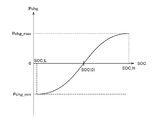
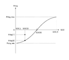
- ECU 200 calculates charge / discharge request amount Pchg based on the current SOC of main battery 70 and a map as shown in FIG. 2, for example.
- the vertical axis in FIG. 2 indicates the required charge / discharge amount Pchg, and the horizontal axis in FIG. 2 indicates the SOC of the main battery 70.
- SOC of the main battery 70 is the threshold value SOC (0)
- the charge / discharge request amount Pchg becomes zero.
- the charge / discharge request amount Pchg becomes a value on the discharge side (positive value). Further, the amount of change in charge / discharge request amount Pchg when the SOC of main battery 70 is larger than threshold value SOC (0) is a value of zero or more. As shown in FIG. 2, when the SOC of the main battery 70 is larger than the threshold SOC (0), the change amount of the charge / discharge request amount Pchg decreases as the SOC increases. When the SOC becomes the upper limit value SOC_H, the charge / discharge request amount Pchg becomes the upper limit value Pchg_max.
- the charge / discharge request amount Pchg becomes a charge-side value (negative value). Further, the amount of change in charge / discharge request amount Pchg when the SOC of main battery 70 is larger than threshold value SOC (0) is a value of zero or more. As shown in FIG. 2, when the SOC of the main battery 70 is smaller than the threshold SOC (0), the change amount of the charge / discharge request amount Pchg decreases as the SOC decreases. When the SOC becomes the lower limit SOC_L, the charge / discharge request amount Pchg becomes the lower limit Pchg_min.
- the upper limit SOC_H and the lower limit SOC_L of the SOC are values defined by the type of the battery, and are adapted experimentally or designally, for example. Further, the upper limit SOC_H of the SOC is the SOC corresponding to the fully charged state of the main battery 70.
- ECU 200 increases charge / discharge request amount Pchg to the charging side, and SOC of main battery 70 exceeds threshold SOC (0). If the charge / discharge request amount Pchg is increased to the discharge side, the SOC balance of the main battery 70 can be stabilized.
- ECU 200 estimates the SOC based on current IB of main battery 70, voltage VB, and battery temperature TB. For example, ECU 200 may estimate OCV (Open Circuit Voltage) based on current IB, voltage VB, and battery temperature TB, and may estimate the SOC of main battery 70 based on the estimated OCV. Alternatively, ECU 200 may estimate the SOC of main battery 70 by, for example, integrating the charging current and discharging current of main battery 70.
- OCV Open Circuit Voltage
- input time T is limited with respect to the magnitude of current IB input during charging.
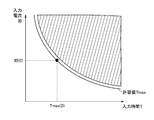
- FIG. 3 shows a predetermined relationship between the current IB input to the main battery 70 and the allowable value Tmax of the input time T of the current IB when the main battery 70 is charged with a constant current. 3 indicates the current IB, and the horizontal axis in FIG. 3 indicates the input time T.
- the allowable value Tmax of the input time T increases as the current IB input to the main battery 70 decreases.
- the allowable value Tmax of the input time T decreases as the current IB input to the main battery 70 increases.
- the relationship between the current IB shown by the solid line in FIG. 3 and the allowable value Tmax of the input time T is set so as to have a certain margin with respect to the shaded area in FIG.
- the hatched area in FIG. 3 is an area where deterioration of the main battery 70 is promoted.
- Tmax (0) is specified from the relationship between the current IB shown by the solid line in FIG. 3 and the allowable value Tmax of the input time T.
- ECU 200 changes charging power limit value Win when main battery 70 is charged so that current IB does not exceed allowable value Tmax of input time T.
- ECU 200 changes charging power limit value Win based on a comparison result between integrated value IB_e of current IB and target value Itag when charging main battery 70, for example. More specifically, the ECU 200 accumulates the current IB by accumulating the current IB detected by the current sensor 158 every time a predetermined calculation cycle elapses after charging of the main battery 70 is started. The value IB_e is calculated. That is, ECU 200 calculates an integrated value IB_e of current IB by adding a value obtained by multiplying current IB detected by current sensor 158 and a predetermined calculation cycle to the previous integrated value.
- ECU 200 calculates target value Itag based on integrated value IB_e of calculated current IB. For example, ECU 200 determines target value Itag so that the value of target value Itag decreases as the value of integrated value IB_e of current IB increases.
- ECU 200 calculates allowable value Tmax of input time T from current IB detected by current sensor 158 and FIG. ECU 200 determines, as target value Itag, a value obtained by subtracting integrated value IB_e of current IB from the product of detected current IB and allowable time Tmax.
- ECU 200 reduces the magnitude of charging power limit value Win when integrated value IB_e of calculated current IB exceeds target value Itag. For example, when the magnitude of the integrated value IB_e of the current IB exceeds the target value Itag, the ECU 200 decreases the magnitude of the charging power limit value Win according to the deviation between the integrated value IB_e and the target value Itag. May be determined. The ECU 200 may increase the amount of decrease in the charge power limit value Win as the deviation between the integrated value IB_e and the target value Itag increases.
- charging power limit value Win is Win (0)
- charging of main battery 70 is performed because SOC of main battery 70 is lower than threshold value SOC (0).
- SOC (0) threshold value
- charging power limit value Win is not limited by factors other than the comparison result between integrated value IB_e and target value Itag.
- the integrated value IB_e of the current IB increases with time.
- the target value Itag decreases as the integrated value IB_e of the current IB increases with time.
- the current IB input to the main battery 70 is reduced by reducing the charging power limit value Win.
- the increase amount of the integrated value IB_e of the current IB is lower than when the charging power limit value Win is not reduced (solid line in FIG. 4).
- the increase amount of the target value Itag decreases when the charge power limit value Win is not decreased (dashed line in FIG. 4), as shown by the one-dot chain line in FIG.
- the charging power limit value Win is decreased after the time point when the integrated value IB_e of the current IB matches the target value Itag. As a result, regenerative energy may not be efficiently recovered during regenerative braking.
- ECU 200 determines a predetermined relationship among speed V of vehicle 1, SOC of main battery 70, current IB input to main battery 70, and allowable value Tmax of input time T.
- the charging request amount Pchg is determined based on the above.
- FIG. 5 shows a functional block diagram of ECU 200 mounted on vehicle 1 according to the present embodiment.
- ECU 200 includes a reference value calculation unit 202, a first determination unit 204, a second determination unit 206, a first Pchg calculation unit 208, a second Pchg calculation unit 210, and a drive control unit 212.
- the reference value calculation unit 202 calculates a reference value Itag_b of the target value Itag.
- the reference value Itag_b is a threshold value for starting correction of the charge / discharge request amount Pchg.
- the reference value calculation unit 202 calculates the reference value Itag_b when the main battery 70 is charged.
- the reference value calculation unit 202 sets the reference value Itag_b so that the reference value Itag_b is higher than when the vehicle 1 is in a state other than the state. Itag_b is calculated.
- the reference value calculation unit 202 may calculate the reference value Itag_b based on the SOC of the main battery 70 and a predetermined map.
- the predetermined map may be set such that the lower the SOC of the main battery 70, the higher the reference value Itag_b, and the higher the SOC of the main battery 70, the lower the reference value Itag_b than when the main battery 70 is low.
- a table or a mathematical formula may be used instead of the predetermined map.
- the first determination unit 204 determines whether or not the SOC of the main battery 70 is within a predetermined range, and the speed V of the vehicle 1 is equal to or higher than a threshold value V (0).
- the first determination unit 204 determines the main battery 70 when the SOC of the main battery 70 is not less than a predetermined value SOC (1) and not more than a predetermined value SOC (2) (> SOC (1)), for example. It is determined that the SOC is within a predetermined range.
- SOC (1) should just be a value more than above-mentioned SOC_L.
- SOC (2) should just be a value below the above-mentioned SOC_H.
- the threshold value V (0) is a value adapted by experiment or the like, and is the speed of the vehicle 1 that can recover a predetermined amount or more of energy when regenerative braking is performed in the vehicle 1.
- the threshold value V (0) may be determined based on, for example, the kinetic energy of the vehicle 1 and / or the potential energy of the vehicle 1.
- the threshold value V (0) may be set according to the gradient of the road surface on which the vehicle 1 is traveling. For example, the threshold value V (0) may be lowered as the slope of the road surface on which the vehicle 1 is traveling is a downward slope.
- the ECU 200 may detect the road gradient using, for example, a G sensor, or may acquire the road gradient based on position information from the navigation system.
- the threshold value V (0) may be set according to the altitude of the road surface on which the vehicle 1 is traveling. For example, the threshold value V (0) may be lowered as the altitude of the road surface on which the vehicle 1 is traveling is higher. ECU 200 may acquire the altitude of the road surface based on position information from the navigation system, for example.
- the first determination unit 204 determines the first determination flag when, for example, the SOC of the main battery 70 is within a predetermined range and the speed V of the vehicle 1 is equal to or higher than the threshold value V (0). May be turned on.
- Second determination unit 206 determines that SOC of main battery 70 is within a predetermined range and speed V of vehicle 1 is equal to or higher than threshold value V (0) by first determination unit 206. Then, it is determined whether or not the target value Itag is smaller than the reference value Itag_b calculated by the reference value calculation unit 202.
- the second determination unit 206 determines, for example, whether or not the target value Itag is smaller than the reference value Itag_b when the first determination flag is in the on state, and when the target value Itag is smaller than the reference value Itag_b.
- the second determination flag may be turned on.
- the first Pchg calculation unit 208 calculates the charge / discharge request amount Pchg based on the SOC of the main battery 70 and a predetermined map when the second determination unit 206 determines that the target value Itag is greater than or equal to the reference value Itag_b.
- the predetermined map is a map showing the relationship between the SOC and the required charge / discharge amount Pchg shown in FIG.
- the first Pchg calculation unit 208 may calculate the charge / discharge request amount Pchg based on the SOC of the main battery 70 and a predetermined map, for example, when the second determination flag is in an off state.
- the second Pchg calculation unit 210 determines the charge / discharge request amount Pchg according to the deviation ⁇ Itag between the target value Itag and the reference value Itag_b. Is calculated.
- the second Pchg calculation unit 210 calculates a provisional charge / discharge request amount Pchg ′ from the current SOC and the predetermined map shown in FIG.
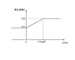
- the second Pchg calculation unit 210 determines the correction coefficient C based on the magnitude (absolute value) of the deviation ⁇ Itag between the target value Itag and the reference value Itag_b and the map shown in FIG.
- the vertical axis in FIG. 6 represents the correction coefficient C
- the horizontal axis in FIG. 6 represents the magnitude of the deviation ⁇ Itag.
- the correction coefficient C is C (0).
- C (0) is described as being “1”, but is not particularly limited as long as it is at least “1” or less.
- the correction coefficient is C (1).
- C (1) is a smaller value than C (0).
- the correction coefficient C is set to C (0) and C (so that the magnitude of the deviation ⁇ Itag and the correction coefficient C have a proportional relationship. 1).
- the correction coefficient C may be C (0).
- the relationship between the deviation ⁇ Itag and the correction coefficient C is not limited to a linear relationship like a proportional relationship, and may be a non-linear relationship.
- the second Pchg calculation unit 210 may determine the final charge / discharge request amount Pchg when the second determination flag is on, for example.
- the drive control unit 212 responds to the required power based on the accelerator pedal depression amount AP and the final charge / discharge request amount Pchg determined in one of the first Pchg calculation unit 208 and the second Pchg calculation unit 210.
- the PCU 60 and the engine 10 are controlled.
- the drive control unit 212 generates a control signal S1 for controlling the engine 10 and a control signal S2 for controlling the PCU 60.
- the drive control unit 212 outputs the generated control signal S1 to the engine 10.
- the drive control unit 212 outputs the generated control signal S2 to the PCU 60.
- the reference value calculation unit 202, the first determination unit 204, the second determination unit 206, the first Pchg calculation unit 208, the second Pchg calculation unit 210, and the drive control unit 212 are all Although the description will be made assuming that the CPU of the ECU 200 functions as software, which is realized by executing a program stored in the memory, it may be realized by hardware. Such a program is recorded on a storage medium and mounted on the vehicle.
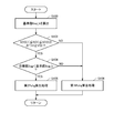
- step (hereinafter, step is referred to as S) 100 ECU 200 calculates reference value Itag_b based on the SOC of main battery 70. Since the method of calculating reference value Itag_b based on the SOC of main battery 70 is as described above, detailed description thereof will not be repeated.
- ECU 200 determines that SOC of main battery 70 is equal to or greater than threshold SOC (1) and within a predetermined range equal to or less than threshold SOC (2), and speed V of vehicle 1 is It is determined whether or not the threshold value is V (0) or more. If the SOC of main battery 70 is within the predetermined range and speed V of vehicle 1 is equal to or higher than threshold value V (0) (YES in S102), the process proceeds to S104. If not (NO in S102), the process proceeds to S106.
- the ECU 200 determines whether or not the target value Itag is smaller than the reference value Itag_b. If target value Itag is smaller than reference value Itag_b (YES in S104), the process proceeds to S108. If not (NO in S104), the process proceeds to S106.
- ECU 200 executes a first Pchg calculation process.
- ECU 200 calculates final charge / discharge request amount Pchg from the current SOC of main battery 70 and the predetermined map shown in FIG. Since the specific calculation method is the same as the calculation method by the first Pchg calculation unit 208 described above, detailed description thereof will not be repeated.
- ECU 200 executes a second Pchg calculation process.
- ECU 200 calculates provisional charge / discharge request amount chg 'from the current SOC of main battery 70 and the predetermined map shown in FIG.
- ECU 200 calculates correction coefficient C from deviation ⁇ Itag using the map shown in FIG.
- the ECU 200 determines a value obtained by multiplying the provisional charge / discharge request amount Pchg ′ by the correction coefficient C as the final charge / discharge request amount Pchg.
- charging power limit value Win is Win (0)
- the main battery 70 is charged by the SOC of the main battery 70 being lower than the threshold SOC (0).
- charging power limit value Win is not limited by factors other than the comparison result between integrated value IB_e and target value Itag.
- the integrated value IB_e of the current IB increases with time.
- the target value Itag decreases as the integrated value IB_e of the current IB increases with time.
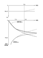
- the reference value Itag_b is calculated based on the SOC of the main battery 70 (S100). Further, when the current SOC of main battery 70 is not within the predetermined range (that is, when the current SOC is smaller than SOC (1) or larger than SOC (2)), or the speed of vehicle 1 If V is lower than threshold value V (0) (NO in S102), the first Pchg calculation process is executed (S106). Further, before time T (3), target value Itag is equal to or larger than reference value Itag_b (NO in S104), so the first Pchg calculation process is executed (S106).
- the final charge / discharge request amount Pchg is determined based on the current SOC of the main battery 70 and the predetermined map shown in FIG.
- target value Itag is smaller than reference value Itag_b (S104).
- the second Pchg calculation process is executed (S108).
- the correction coefficient C is determined based on the magnitude of the deviation ⁇ Itag and the map shown in FIG. Further, provisional charge / discharge request amount Pchg 'is determined based on the current SOC of main battery 70 and the predetermined map shown in FIG. A value obtained by multiplying the determined correction coefficient C by the provisional charge / discharge request amount Pchg 'is determined as the final charge / discharge request amount Pchg.
- the correction coefficient C is assumed to be C (2).
- C (2) is smaller than C (0) and larger than C (1).
- the final charge / discharge request amount Pchg (1) calculated by executing the second Pchg calculation process is calculated by executing the first Pchg calculation process when the current SOC is the same.
- the value is smaller than the final charge / discharge request amount Pchg (0).
- the integration of the current IB is greater than when the second Pchg calculation process is not executed (thin solid line in FIG. 8).
- the time change amount (increase amount) of the value IB_e decreases.
- the time change amount (reduction amount) of the target value Itag is greater than when the second Pchg calculation process is not executed (thin broken line in FIG. 8). Decreases.
- the time point when the integrated value IB_e and the target value Itag match is a time point later than the time point when the integrated value IB_e and the target value Itag match (time T (0)) when the second Pchg calculation process is not executed.
- the charging power limit value Win is restrained from being limited at time T (0). That is, from the time T (0) to the time when the integrated value IB_e and the target value Itag coincide with each other, Win (0) is maintained as the charging power limit value Win. Therefore, regenerative energy can be efficiently recovered during regenerative braking.
- the speed V of the vehicle 1, the SOC of the main battery 70, the current IB input to the main battery 70, and the allowable value Tmax of the input time T are stored in advance.
- the required charging amount Pchg is determined based on the determined relationship.
- the time point at which the integrated value IB_e of the current IB matches the target value Itag can be delayed.
- By delaying the time point at which the integrated value IB_e matches the target value Itag it is possible to suppress a decrease in the magnitude of the charging power limit value Win.
- regenerative energy can be efficiently recovered during regenerative braking. Therefore, it is possible to provide a vehicle and a vehicle control method that can efficiently recover regenerative energy while the vehicle is running.
- the ECU 200 has been described as determining the target value Itag as a value obtained by subtracting the integrated value IB_e of the current IB from the product of the current IB and the allowable value Tmax of the input time T.
- the method for determining Itag is not limited to the method described above.
- ECU 200 may determine, for example, a value obtained by adding (or subtracting) a predetermined value to a value obtained by subtracting integrated value IB_e of current IB from the product of current IB and allowable value Tmax of input time T as target value Itag. .
- ECU 200 may determine, as target value Itag, a value obtained by multiplying a product of current IB and allowable value Tmax of input time T by subtracting integrated value IB_e of current IB and a predetermined coefficient.
- a predetermined map is used such that the lower the SOC of main battery 70 is, the higher reference value Itag_b is, and the higher the SOC of main battery 70 is, the lower reference value Itag_b is lower than the lower value.
- the reference value Itag_b has been described as being set. The higher the reference value Itag_b, the earlier the execution of the second Pchg calculation process. Therefore, the time point at which the integrated value IB_e matches the target value Itag can be further delayed compared to the case where the reference value Itag_b is low. Therefore, more regenerative energy can be recovered during regenerative braking.
- the ECU 200 has been described as determining the final charge / discharge request amount Pchg as follows. That is, the ECU 200 determines the correction coefficient C corresponding to the deviation ⁇ Itag. ECU 200 calculates provisional charge / discharge request amount Pchg 'based on the current SOC of main battery 70, the predetermined map shown in FIG. The ECU 200 determines the final charge / discharge request amount Pchg by multiplying the correction coefficient C by the charge / discharge request amount Pchg '.
- the method of determining the final charge / discharge request amount Pchg by correcting the provisional charge / discharge request amount Pchg ′ is limited to the method of multiplying the provisional charge / discharge request amount Pchg ′ by the correction coefficient C. It is not something.
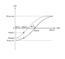
- the ECU 200 may calculate the offset amount F of the map shown in FIG. 9 based on, for example, the deviation ⁇ Itag. As shown in FIG. 10, ECU 200 may move the curve shown by the solid line in FIG. 10 in the direction in which the SOC decreases by the calculated offset amount F, and specify the curve shown by the broken line in FIG. ECU 200 may calculate final charge / discharge request amount Pchg based on the current SOC of main battery 70 and the specified curve shown by the broken line in FIG.
- Pchg (1) calculated using the curve shown by the broken line in FIG. 10 is calculated as the final charge / discharge request amount Pchg. .
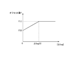
- ECU200 determines offset amount F based on the magnitude
- the vertical axis in FIG. 11 indicates the offset amount F, and the horizontal axis in FIG. 11 indicates the magnitude of ⁇ Itag. Further, the positive direction of the offset amount F is a direction in which the SOC decreases.
- the offset amount F is F (0).
- F (0) is described as being “0”, but is not particularly limited as long as it is at least “0” or more.
- the offset amount F is F (1).
- F (1) is a value larger than F (0).
- the offset amount F is set to F (0) and F (so that the magnitude of the deviation ⁇ Itag and the offset amount F have a proportional relationship. 1).
- the offset amount F may be F (0).
- the relationship between the deviation ⁇ Itag and the offset amount F is not limited to a linear relationship like a proportional relationship, and may be a non-linear relationship.
- ECU 200 executes the first Pchg calculation process when target value Itag is greater than or equal to reference value Itag_b, and executes the second Pchg calculation process when target value Itag is smaller than reference value Itag_b.
- the ECU 200 calculates the final charge / discharge request amount Pchg using, for example, the deviation ⁇ Itag and a predetermined map as shown in FIG. 12 when the main battery 70 is charged. May be.
- the predetermined map shown in FIG. 12 when the deviation ⁇ Itag is smaller than zero (that is, when the target value Itag is smaller than the reference value Itag), the correction coefficient C is C (1).
- the correction coefficient is C (0).
- the correction coefficient C is set to C (1) so that the deviation ⁇ Itag and the correction coefficient C have a proportional relationship.
- C (0) the relationship between the deviation ⁇ Itag and the correction coefficient C is not limited to a linear relationship like a proportional relationship, and may be a non-linear relationship.
- the vehicle 1 having the driving wheel 80 as the front wheel is shown as an example, but the driving method is not particularly limited thereto.
- the vehicle 1 may have a rear wheel as a driving wheel.
- vehicle 1 may be a vehicle in which first MG 20 or second MG 30 in FIG. 1 is omitted.
- vehicle 1 may be a vehicle in which second MG 30 in FIG. 1 is coupled to a drive shaft for driving rear wheels instead of front wheel drive shaft 16.
- a speed change mechanism may be provided between drive shaft 16 and speed reducer 58 or between drive shaft 16 and second MG 30.
- the vehicle 1 may be any vehicle equipped with a lithium ion battery, and is not particularly limited to a hybrid vehicle.
- the vehicle 1 may be an electric vehicle or a vehicle using only an engine as a power source.
Landscapes
- Engineering & Computer Science (AREA)
- Transportation (AREA)
- Mechanical Engineering (AREA)
- Chemical & Material Sciences (AREA)
- Combustion & Propulsion (AREA)
- Power Engineering (AREA)
- Life Sciences & Earth Sciences (AREA)
- Sustainable Development (AREA)
- Sustainable Energy (AREA)
- Automation & Control Theory (AREA)
- Electric Propulsion And Braking For Vehicles (AREA)
- Charge And Discharge Circuits For Batteries Or The Like (AREA)
- Hybrid Electric Vehicles (AREA)
- Secondary Cells (AREA)
Abstract
Description
Claims (9)
- 車両(1)に搭載されたリチウムイオン電池(70)と、
前記リチウムイオン電池(70)の残容量を検出するための残容量検出部(156,158,160)と、
前記車両(1)の速度を検出するための速度検出部(13)と、
前記車両(1)の前記速度と、前記リチウムイオン電池(70)の前記残容量と、前記リチウムイオン電池(70)の特性に対応した入力電流と入力時間の許容値との予め定められた関係とに基づいて充電要求量を決定し、決定された前記充電要求量に基づいて前記車両(1)を制御するための制御部(200)とを含む、車両。 - 前記制御部(200)は、前記入力電流の積算値と、前記入力電流および前記予め定められた関係に基づいて決定される前記積算値の目標値との偏差に応じて前記充電要求量を決定する、請求項1に記載の車両。
- 前記制御部(200)は、前記入力電流の前記積算値と前記目標値とが一致した場合に充電電力制限値の大きさを低下させる、請求項2に記載の車両。
- 前記制御部(200)は、前記偏差の大きさがしきい値よりも大きい場合には前記リチウムイオン電池(70)の残容量に基づく第1要求量を前記充電要求量として決定し、前記偏差の大きさが前記しきい値よりも小さい場合には前記第1要求量を補正して、前記充電要求量を決定する、請求項2に記載の車両。
- 前記制御部(200)は、前記偏差の大きさに応じた分だけ前記第1要求量よりも低い値を前記充電要求量として決定する、請求項4に記載の車両。
- 前記制御部(200)は、前記偏差の大きさに対応した補正係数を算出して、前記第1要求量と前記補正係数とを乗算した値を前記充電要求量として決定する、請求項5に記載の車両。
- 前記制御部(200)は、前記偏差の大きさに対応したオフセット量を算出して、前記残容量と前記第1要求量との関係を前記オフセット量に応じて変更して、前記残容量と変更された前記関係とに基づいて前記充電要求量を決定する、請求項5に記載の車両。
- 前記制御部(200)は、前記車両(1)の前記速度が予め定められた速度よりも高い場合に、前記リチウムイオン電池(70)の前記残容量と、前記予め定められた関係とに基づいて前記充電要求量を決定する、請求項1に記載の車両。
- リチウムイオン電池(70)を搭載した車両(1)に用いられる車両用制御方法であって、
前記リチウムイオン電池(70)の残容量を検出するステップと、
前記車両(1)の速度を検出するステップと、
前記車両(1)の前記速度と、前記リチウムイオン電池(70)の前記残容量と、前記リチウムイオン電池(70)に対する入力電流と入力時間の許容値との予め定められた関係とに基づいて充電要求量を決定し、決定された前記充電要求量を満足するように前記車両(1)を制御するステップとを含む、車両用制御方法。
Priority Applications (5)
| Application Number | Priority Date | Filing Date | Title |
|---|---|---|---|
| EP11863905.3A EP2700550B1 (en) | 2011-04-22 | 2011-04-22 | Vehicle and vehicle control method |
| CN201180070335.5A CN103492251B (zh) | 2011-04-22 | 2011-04-22 | 车辆及车辆用控制方法 |
| JP2013510802A JP5664769B2 (ja) | 2011-04-22 | 2011-04-22 | 車両および車両用制御方法 |
| US14/009,490 US8989939B2 (en) | 2011-04-22 | 2011-04-22 | Vehicle and vehicle control method |
| PCT/JP2011/059903 WO2012144061A1 (ja) | 2011-04-22 | 2011-04-22 | 車両および車両用制御方法 |
Applications Claiming Priority (1)
| Application Number | Priority Date | Filing Date | Title |
|---|---|---|---|
| PCT/JP2011/059903 WO2012144061A1 (ja) | 2011-04-22 | 2011-04-22 | 車両および車両用制御方法 |
Publications (1)
| Publication Number | Publication Date |
|---|---|
| WO2012144061A1 true WO2012144061A1 (ja) | 2012-10-26 |
Family
ID=47041209
Family Applications (1)
| Application Number | Title | Priority Date | Filing Date |
|---|---|---|---|
| PCT/JP2011/059903 Ceased WO2012144061A1 (ja) | 2011-04-22 | 2011-04-22 | 車両および車両用制御方法 |
Country Status (5)
| Country | Link |
|---|---|
| US (1) | US8989939B2 (ja) |
| EP (1) | EP2700550B1 (ja) |
| JP (1) | JP5664769B2 (ja) |
| CN (1) | CN103492251B (ja) |
| WO (1) | WO2012144061A1 (ja) |
Cited By (4)
| Publication number | Priority date | Publication date | Assignee | Title |
|---|---|---|---|---|
| WO2015019165A1 (en) * | 2013-08-09 | 2015-02-12 | Toyota Jidosha Kabushiki Kaisha | Control apparatus and control method for hybrid vehicle |
| JP2015050896A (ja) * | 2013-09-04 | 2015-03-16 | 株式会社デンソー | ハイブリッド車制御システム |
| CN106064563A (zh) * | 2015-04-24 | 2016-11-02 | 丰田自动车株式会社 | 用于车辆的控制装置以及用于车辆的控制方法 |
| JP2017065566A (ja) * | 2015-09-30 | 2017-04-06 | トヨタ自動車株式会社 | ハイブリッド車両の制御装置 |
Families Citing this family (8)
| Publication number | Priority date | Publication date | Assignee | Title |
|---|---|---|---|---|
| US9656568B2 (en) * | 2013-04-15 | 2017-05-23 | Volvo Truck Corporation | Method and arrangement for error detection during charging of an energy storage system |
| CN107078537B (zh) * | 2014-11-04 | 2018-10-12 | 本田技研工业株式会社 | 充电控制装置和充电控制方法 |
| JP6213494B2 (ja) * | 2015-02-18 | 2017-10-18 | トヨタ自動車株式会社 | ハイブリッド車両 |
| JP6304193B2 (ja) * | 2015-10-22 | 2018-04-04 | トヨタ自動車株式会社 | 車両制御装置 |
| IT201600105858A1 (it) * | 2016-10-20 | 2018-04-20 | Magneti Marelli Spa | Impianto elettrico provvisto di un assieme di accumulo a doppia tensione per un veicolo |
| JP7401455B2 (ja) * | 2018-04-13 | 2023-12-19 | ローベルト ボツシユ ゲゼルシヤフト ミツト ベシユレンクテル ハフツング | 最適化システム及び最適化方法 |
| CN109150040B (zh) * | 2018-09-10 | 2020-10-13 | 上海法雷奥汽车电器系统有限公司 | 一种发电机控制方法及控制电路 |
| CN111688497B (zh) * | 2020-06-19 | 2022-04-15 | 清华大学 | 电动汽车电池高荷电状态下回馈制动系统及控制方法 |
Citations (4)
| Publication number | Priority date | Publication date | Assignee | Title |
|---|---|---|---|---|
| JP2005137091A (ja) * | 2003-10-29 | 2005-05-26 | Toyota Motor Corp | 二次電池の制御装置および制御方法 |
| JP2009248913A (ja) | 2008-04-10 | 2009-10-29 | Toyota Motor Corp | ハイブリッド車およびその制御方法 |
| WO2010005079A1 (ja) * | 2008-07-11 | 2010-01-14 | トヨタ自動車株式会社 | バッテリの充放電制御装置、およびこれを備えたハイブリッド自動車 |
| JP2011079447A (ja) * | 2009-10-08 | 2011-04-21 | Hitachi Ltd | ハイブリッド走行制御システム |
Family Cites Families (16)
| Publication number | Priority date | Publication date | Assignee | Title |
|---|---|---|---|---|
| JP2002112402A (ja) * | 2000-09-29 | 2002-04-12 | Mitsubishi Motors Corp | 電気自動車の制御装置 |
| US20040090195A1 (en) * | 2001-06-11 | 2004-05-13 | Motsenbocker Marvin A. | Efficient control, monitoring and energy devices for vehicles such as watercraft |
| DE102004043589B4 (de) * | 2004-09-09 | 2018-11-15 | Zf Friedrichshafen Ag | Vorrichtung und Verfahren zur Bestimmung der Antriebsleistungsverteilung in einem Hybrid-Antriebsstrang eines Fahrzeuges |
| JP4265629B2 (ja) * | 2006-08-01 | 2009-05-20 | トヨタ自動車株式会社 | 二次電池の充放電制御装置およびそれを搭載したハイブリッド車両 |
| JP4274257B2 (ja) * | 2007-02-20 | 2009-06-03 | トヨタ自動車株式会社 | ハイブリッド車両 |
| JP4305541B2 (ja) * | 2007-03-28 | 2009-07-29 | トヨタ自動車株式会社 | ハイブリッド車両の制御装置 |
| JP5125938B2 (ja) * | 2008-09-24 | 2013-01-23 | 富士通株式会社 | バグ検出支援プログラム、類似構文識別情報一覧出力プログラム、バグ検出支援装置およびバグ検出支援方法 |
| JP4941595B2 (ja) * | 2009-02-09 | 2012-05-30 | トヨタ自動車株式会社 | 電源システム |
| JP5146502B2 (ja) * | 2009-11-12 | 2013-02-20 | トヨタ自動車株式会社 | 二次電池の充放電制御装置 |
| JP5433387B2 (ja) * | 2009-11-30 | 2014-03-05 | 株式会社日立製作所 | 車両用機器冷却暖房システム |
| US8392044B2 (en) * | 2010-07-28 | 2013-03-05 | Deere & Company | Robotic mower boundary sensing system |
| US9807925B2 (en) * | 2010-07-28 | 2017-11-07 | Deere & Company | Robotic mower area coverage system |
| US8352113B2 (en) * | 2010-07-28 | 2013-01-08 | Deere & Company | Robotic mower boundary coverage system |
| US8433468B2 (en) * | 2010-07-28 | 2013-04-30 | Deere & Company | Robotic mower home finding system |
| US20120029752A1 (en) * | 2010-07-28 | 2012-02-02 | Johnson David A | Robotic Mower Stuck Detection System |
| US8549826B2 (en) * | 2011-07-25 | 2013-10-08 | Deere & Company | Robotic mower launch point system |
-
2011
- 2011-04-22 JP JP2013510802A patent/JP5664769B2/ja active Active
- 2011-04-22 CN CN201180070335.5A patent/CN103492251B/zh not_active Expired - Fee Related
- 2011-04-22 US US14/009,490 patent/US8989939B2/en not_active Expired - Fee Related
- 2011-04-22 EP EP11863905.3A patent/EP2700550B1/en active Active
- 2011-04-22 WO PCT/JP2011/059903 patent/WO2012144061A1/ja not_active Ceased
Patent Citations (4)
| Publication number | Priority date | Publication date | Assignee | Title |
|---|---|---|---|---|
| JP2005137091A (ja) * | 2003-10-29 | 2005-05-26 | Toyota Motor Corp | 二次電池の制御装置および制御方法 |
| JP2009248913A (ja) | 2008-04-10 | 2009-10-29 | Toyota Motor Corp | ハイブリッド車およびその制御方法 |
| WO2010005079A1 (ja) * | 2008-07-11 | 2010-01-14 | トヨタ自動車株式会社 | バッテリの充放電制御装置、およびこれを備えたハイブリッド自動車 |
| JP2011079447A (ja) * | 2009-10-08 | 2011-04-21 | Hitachi Ltd | ハイブリッド走行制御システム |
Cited By (5)
| Publication number | Priority date | Publication date | Assignee | Title |
|---|---|---|---|---|
| WO2015019165A1 (en) * | 2013-08-09 | 2015-02-12 | Toyota Jidosha Kabushiki Kaisha | Control apparatus and control method for hybrid vehicle |
| KR101752111B1 (ko) | 2013-08-09 | 2017-06-28 | 도요타지도샤가부시키가이샤 | 하이브리드 차량용 제어 장치 및 제어 방법 |
| JP2015050896A (ja) * | 2013-09-04 | 2015-03-16 | 株式会社デンソー | ハイブリッド車制御システム |
| CN106064563A (zh) * | 2015-04-24 | 2016-11-02 | 丰田自动车株式会社 | 用于车辆的控制装置以及用于车辆的控制方法 |
| JP2017065566A (ja) * | 2015-09-30 | 2017-04-06 | トヨタ自動車株式会社 | ハイブリッド車両の制御装置 |
Also Published As
| Publication number | Publication date |
|---|---|
| CN103492251A (zh) | 2014-01-01 |
| JP5664769B2 (ja) | 2015-02-04 |
| EP2700550A4 (en) | 2014-08-06 |
| EP2700550B1 (en) | 2020-01-15 |
| US20140032027A1 (en) | 2014-01-30 |
| EP2700550A1 (en) | 2014-02-26 |
| CN103492251B (zh) | 2016-04-20 |
| JPWO2012144061A1 (ja) | 2014-07-28 |
| US8989939B2 (en) | 2015-03-24 |
Similar Documents
| Publication | Publication Date | Title |
|---|---|---|
| JP5664769B2 (ja) | 車両および車両用制御方法 | |
| JP6011541B2 (ja) | 充電制御装置および充電制御方法 | |
| JP5879251B2 (ja) | 電動機の駆動制御装置 | |
| KR100993301B1 (ko) | 차량의 제어 장치 및 제어 방법 | |
| US10351015B2 (en) | Hybrid vehicle | |
| JP2011072067A (ja) | 車両の電源システムおよびそれを備える電動車両 | |
| JP2019171916A (ja) | 発電機を備える車両 | |
| JP5598555B2 (ja) | 車両および車両用制御方法 | |
| JP5923888B2 (ja) | ハイブリッド車両およびその制御方法 | |
| JP6075018B2 (ja) | 電動車両の制御装置およびそれを備える電動車両、ならびに電動車両の制御方法 | |
| JP2013220682A (ja) | ハイブリッド車 | |
| JP5765419B2 (ja) | 車両および車両用制御方法 | |
| WO2012101798A1 (ja) | 車両および車両の制御方法 | |
| JP5607434B2 (ja) | 車両の制御装置 | |
| JP6303620B2 (ja) | ハイブリッド車両 | |
| JP2012166676A (ja) | 車両および車両用制御方法 | |
| JP5761327B2 (ja) | ハイブリッド車両の制御装置 | |
| JP5927792B2 (ja) | 車両用制御装置および車両用制御方法 | |
| WO2006064662A1 (ja) | 車両の制御装置 | |
| JP5152295B2 (ja) | 車両の制御装置 | |
| JP2017094835A (ja) | ハイブリッド車両の回生電力量制御システム、ハイブリッド車両及びハイブリッド車両の回生電力量制御方法 | |
| JP2012224304A (ja) | 車両の制振制御装置 | |
| JP5699841B2 (ja) | ハイブリッド自動車 |
Legal Events
| Date | Code | Title | Description |
|---|---|---|---|
| WWE | Wipo information: entry into national phase |
Ref document number: 201180070335.5 Country of ref document: CN |
|
| 121 | Ep: the epo has been informed by wipo that ep was designated in this application |
Ref document number: 11863905 Country of ref document: EP Kind code of ref document: A1 |
|
| ENP | Entry into the national phase |
Ref document number: 2013510802 Country of ref document: JP Kind code of ref document: A |
|
| WWE | Wipo information: entry into national phase |
Ref document number: 14009490 Country of ref document: US |
|
| NENP | Non-entry into the national phase |
Ref country code: DE |
|
| WWE | Wipo information: entry into national phase |
Ref document number: 2011863905 Country of ref document: EP |