WO2012144877A2 - Apparatus for quantizing linear predictive coding coefficients, sound encoding apparatus, apparatus for de-quantizing linear predictive coding coefficients, sound decoding apparatus, and electronic device therefor - Google Patents
Apparatus for quantizing linear predictive coding coefficients, sound encoding apparatus, apparatus for de-quantizing linear predictive coding coefficients, sound decoding apparatus, and electronic device therefor Download PDFInfo
- Publication number
- WO2012144877A2 WO2012144877A2 PCT/KR2012/003127 KR2012003127W WO2012144877A2 WO 2012144877 A2 WO2012144877 A2 WO 2012144877A2 KR 2012003127 W KR2012003127 W KR 2012003127W WO 2012144877 A2 WO2012144877 A2 WO 2012144877A2
- Authority
- WO
- WIPO (PCT)
- Prior art keywords
- quantization
- path
- inter
- quantizes
- quantizer
- Prior art date
- Legal status (The legal status is an assumption and is not a legal conclusion. Google has not performed a legal analysis and makes no representation as to the accuracy of the status listed.)
- Ceased
Links
Images


Classifications
-
- G—PHYSICS
- G10—MUSICAL INSTRUMENTS; ACOUSTICS
- G10L—SPEECH ANALYSIS TECHNIQUES OR SPEECH SYNTHESIS; SPEECH RECOGNITION; SPEECH OR VOICE PROCESSING TECHNIQUES; SPEECH OR AUDIO CODING OR DECODING
- G10L19/00—Speech or audio signals analysis-synthesis techniques for redundancy reduction, e.g. in vocoders; Coding or decoding of speech or audio signals, using source filter models or psychoacoustic analysis
- G10L19/04—Speech or audio signals analysis-synthesis techniques for redundancy reduction, e.g. in vocoders; Coding or decoding of speech or audio signals, using source filter models or psychoacoustic analysis using predictive techniques
- G10L19/16—Vocoder architecture
- G10L19/18—Vocoders using multiple modes
- G10L19/24—Variable rate codecs, e.g. for generating different qualities using a scalable representation such as hierarchical encoding or layered encoding
-
- G—PHYSICS
- G10—MUSICAL INSTRUMENTS; ACOUSTICS
- G10L—SPEECH ANALYSIS TECHNIQUES OR SPEECH SYNTHESIS; SPEECH RECOGNITION; SPEECH OR VOICE PROCESSING TECHNIQUES; SPEECH OR AUDIO CODING OR DECODING
- G10L19/00—Speech or audio signals analysis-synthesis techniques for redundancy reduction, e.g. in vocoders; Coding or decoding of speech or audio signals, using source filter models or psychoacoustic analysis
- G10L19/005—Correction of errors induced by the transmission channel, if related to the coding algorithm
-
- G—PHYSICS
- G10—MUSICAL INSTRUMENTS; ACOUSTICS
- G10L—SPEECH ANALYSIS TECHNIQUES OR SPEECH SYNTHESIS; SPEECH RECOGNITION; SPEECH OR VOICE PROCESSING TECHNIQUES; SPEECH OR AUDIO CODING OR DECODING
- G10L19/00—Speech or audio signals analysis-synthesis techniques for redundancy reduction, e.g. in vocoders; Coding or decoding of speech or audio signals, using source filter models or psychoacoustic analysis
- G10L19/02—Speech or audio signals analysis-synthesis techniques for redundancy reduction, e.g. in vocoders; Coding or decoding of speech or audio signals, using source filter models or psychoacoustic analysis using spectral analysis, e.g. transform vocoders or subband vocoders
- G10L19/032—Quantisation or dequantisation of spectral components
- G10L19/038—Vector quantisation, e.g. TwinVQ audio
-
- G—PHYSICS
- G10—MUSICAL INSTRUMENTS; ACOUSTICS
- G10L—SPEECH ANALYSIS TECHNIQUES OR SPEECH SYNTHESIS; SPEECH RECOGNITION; SPEECH OR VOICE PROCESSING TECHNIQUES; SPEECH OR AUDIO CODING OR DECODING
- G10L19/00—Speech or audio signals analysis-synthesis techniques for redundancy reduction, e.g. in vocoders; Coding or decoding of speech or audio signals, using source filter models or psychoacoustic analysis
- G10L19/04—Speech or audio signals analysis-synthesis techniques for redundancy reduction, e.g. in vocoders; Coding or decoding of speech or audio signals, using source filter models or psychoacoustic analysis using predictive techniques
- G10L19/06—Determination or coding of the spectral characteristics, e.g. of the short-term prediction coefficients
-
- G—PHYSICS
- G10—MUSICAL INSTRUMENTS; ACOUSTICS
- G10L—SPEECH ANALYSIS TECHNIQUES OR SPEECH SYNTHESIS; SPEECH RECOGNITION; SPEECH OR VOICE PROCESSING TECHNIQUES; SPEECH OR AUDIO CODING OR DECODING
- G10L19/00—Speech or audio signals analysis-synthesis techniques for redundancy reduction, e.g. in vocoders; Coding or decoding of speech or audio signals, using source filter models or psychoacoustic analysis
- G10L19/04—Speech or audio signals analysis-synthesis techniques for redundancy reduction, e.g. in vocoders; Coding or decoding of speech or audio signals, using source filter models or psychoacoustic analysis using predictive techniques
- G10L19/08—Determination or coding of the excitation function; Determination or coding of the long-term prediction parameters
- G10L19/087—Determination or coding of the excitation function; Determination or coding of the long-term prediction parameters using mixed excitation models, e.g. MELP, MBE, split band LPC or HVXC
-
- G—PHYSICS
- G10—MUSICAL INSTRUMENTS; ACOUSTICS
- G10L—SPEECH ANALYSIS TECHNIQUES OR SPEECH SYNTHESIS; SPEECH RECOGNITION; SPEECH OR VOICE PROCESSING TECHNIQUES; SPEECH OR AUDIO CODING OR DECODING
- G10L19/00—Speech or audio signals analysis-synthesis techniques for redundancy reduction, e.g. in vocoders; Coding or decoding of speech or audio signals, using source filter models or psychoacoustic analysis
- G10L19/04—Speech or audio signals analysis-synthesis techniques for redundancy reduction, e.g. in vocoders; Coding or decoding of speech or audio signals, using source filter models or psychoacoustic analysis using predictive techniques
- G10L19/08—Determination or coding of the excitation function; Determination or coding of the long-term prediction parameters
- G10L19/10—Determination or coding of the excitation function; Determination or coding of the long-term prediction parameters the excitation function being a multipulse excitation
- G10L19/107—Sparse pulse excitation, e.g. by using algebraic codebook
-
- G—PHYSICS
- G10—MUSICAL INSTRUMENTS; ACOUSTICS
- G10L—SPEECH ANALYSIS TECHNIQUES OR SPEECH SYNTHESIS; SPEECH RECOGNITION; SPEECH OR VOICE PROCESSING TECHNIQUES; SPEECH OR AUDIO CODING OR DECODING
- G10L19/00—Speech or audio signals analysis-synthesis techniques for redundancy reduction, e.g. in vocoders; Coding or decoding of speech or audio signals, using source filter models or psychoacoustic analysis
- G10L19/04—Speech or audio signals analysis-synthesis techniques for redundancy reduction, e.g. in vocoders; Coding or decoding of speech or audio signals, using source filter models or psychoacoustic analysis using predictive techniques
- G10L19/08—Determination or coding of the excitation function; Determination or coding of the long-term prediction parameters
- G10L19/12—Determination or coding of the excitation function; Determination or coding of the long-term prediction parameters the excitation function being a code excitation, e.g. in code excited linear prediction [CELP] vocoders
-
- G—PHYSICS
- G10—MUSICAL INSTRUMENTS; ACOUSTICS
- G10L—SPEECH ANALYSIS TECHNIQUES OR SPEECH SYNTHESIS; SPEECH RECOGNITION; SPEECH OR VOICE PROCESSING TECHNIQUES; SPEECH OR AUDIO CODING OR DECODING
- G10L19/00—Speech or audio signals analysis-synthesis techniques for redundancy reduction, e.g. in vocoders; Coding or decoding of speech or audio signals, using source filter models or psychoacoustic analysis
- G10L19/04—Speech or audio signals analysis-synthesis techniques for redundancy reduction, e.g. in vocoders; Coding or decoding of speech or audio signals, using source filter models or psychoacoustic analysis using predictive techniques
- G10L19/16—Vocoder architecture
- G10L19/18—Vocoders using multiple modes
-
- G—PHYSICS
- G10—MUSICAL INSTRUMENTS; ACOUSTICS
- G10L—SPEECH ANALYSIS TECHNIQUES OR SPEECH SYNTHESIS; SPEECH RECOGNITION; SPEECH OR VOICE PROCESSING TECHNIQUES; SPEECH OR AUDIO CODING OR DECODING
- G10L19/00—Speech or audio signals analysis-synthesis techniques for redundancy reduction, e.g. in vocoders; Coding or decoding of speech or audio signals, using source filter models or psychoacoustic analysis
- G10L19/04—Speech or audio signals analysis-synthesis techniques for redundancy reduction, e.g. in vocoders; Coding or decoding of speech or audio signals, using source filter models or psychoacoustic analysis using predictive techniques
-
- G—PHYSICS
- G10—MUSICAL INSTRUMENTS; ACOUSTICS
- G10L—SPEECH ANALYSIS TECHNIQUES OR SPEECH SYNTHESIS; SPEECH RECOGNITION; SPEECH OR VOICE PROCESSING TECHNIQUES; SPEECH OR AUDIO CODING OR DECODING
- G10L19/00—Speech or audio signals analysis-synthesis techniques for redundancy reduction, e.g. in vocoders; Coding or decoding of speech or audio signals, using source filter models or psychoacoustic analysis
- G10L2019/0001—Codebooks
- G10L2019/0004—Design or structure of the codebook
- G10L2019/0005—Multi-stage vector quantisation
Definitions
- Apparatuses, devices, and articles of manufacture consistent with the present disclosure relate to quantization and de-quantization of linear predictive coding coefficients, and more particularly, to an apparatus for efficiently quantizing linear predictive coding coefficients with low complexity, a sound encoding apparatus employing the quantizing apparatus, an apparatus for de-quantizing linear predictive coding coefficients, a sound decoding apparatus employing the de-quantizing apparatus, and electronic devices therefor.
- LPC Linear Predictive Coding
- quantization is performed by converting LPC coefficients to other coefficients easy to check the stability of a filter, advantageous to interpolation, and having a good quantization characteristic. It is mainly preferred that the quantization is performed by converting LPC coefficients to Line Spectral Frequency (LSF) or Immittance Spectral Frequency (ISF) coefficients.
- LSF Line Spectral Frequency
- ISF Immittance Spectral Frequency
- a method of quantizing LPC coefficients may increase a quantization gain by using a high inter-frame correlation of LSF coefficients in a frequency domain and a time domain.
- LSF coefficients indicate a frequency characteristic of a short-time sound, and for frames in which a frequency characteristic of an input sound is rapidly changed, LSF coefficients of the frames are also rapidly changed.
- quantization performance of the quantizer decreases.
- LPC Linear Predictive Coding
- a quantizing apparatus comprising a quantization path determination unit that determines one of a plurality of paths, including a first path not using inter-frame prediction and a second path using the inter-frame prediction, as a quantization path of an input signal, based on a criterion before quantization of the input signal; a first quantization unit that quantizes the input signal, if the first path is determined as the quantization path of the input signal; and a second quantization unit that quantizes the input signal, if the second path is determined as the quantization path of the input signal.
- an encoding apparatus comprising a coding mode determination unit that determiens a coding mode of an input signal; a quantization unit that determines one of a plurality of paths, including a first path not using inter-frame prediction and a second path using the inter-frame prediction, as a quantization path of the input signal based on a criterion before quantization of the input signal and that quantizesthe input signal by using one of a first quantization scheme and a second quantization scheme according to the determined quantization path; a variable mode encoding unit that encodes the quantized input signal in the coding mode; and a parameter encoding unit that generates a bitstream including one of a result quantized in the first quantization unit and a result quantized in the second quantization unit, the coding mode of the input signal, and path information related to the quantization of the input signal.
- a de-quantizing apparatus comprising a de-quantization path determination unit that determines one of a plurality of paths, including a first path not using inter-frame prediction and a second path using the inter-frame prediction, as a de-quantization path of Linear Predictive Coding (LPC) parameters based on quantization path information included in a bitstream; a first de-quantization unit that de-quantizes the LPC parameters, if the first path is determined as the de-quantization path of the LPC parameters; and a second de-quantization unit that de- quantizes the LPC parameters, if the second path is selected as the de-quantization path of the LPC parameters, wherein the quantization path information is determined based on a criterion before quantization of an input signal in an encoding end.
- LPC Linear Predictive Coding
- a decoding apparatus comprising a parameter decoding unit that decodes Linear Predictive Coding (LPC) parameters and a coding mode included in a bitstream; a de-quantization unit that de-quantizes the decoded LPC parameters by using one of a first de-quantization scheme not using inter-frame prediction and a second de-quantization scheme using the inter-frame prediction based on quantization path information included in the bitstream; and a variable mode decoding unit that decodes the de-quantized LPC parameters in the decoded coding mode, wherein the quantization path information is determined based on a criterion before quantization of an input signal in an encoding end.
- LPC Linear Predictive Coding
- FIG. 8 is a block diagram of a quantization path selector according to another exemplary embodiment
- FIG. 11 is a block diagram of an LPC coefficient quantizer according to another exemplary embodiment.
- FIG. 14 is a block diagram of an LPC coefficient quantizer according to another exemplary embodiment
- FIG. 15 is a block diagram of an LPC coefficient quantizer according to another exemplary embodiment
- FIG. 18 is a block diagram of an LPC coefficient quantizer according to another exemplary embodiment.
- FIG. 22 is a flowchart illustrating an operation of a quantizer type selecting method, according to an exemplary embodiment
- FIG. 23 is a block diagram of a sound decoding apparatus according to an exemplary embodiment
- FIG. 25 is a block diagram of an LPC coefficient de-quantizer according to another exemplary embodiment.
- FIG. 30 is a block diagram of an electronic device including a decoding module, according to an exemplary embodiment.
- FIG. 1 is a block diagram of a sound encoding apparatus 100 according to an exemplary embodiment.
- the ISF/LSF quantizer 315 may quantize the ISF coefficients or the LSF coefficients converted from the LPC coefficients of the frame end of the current frame.
- the ISF/LSF quantizer 315 may obtain an optimal quantization index in an input coding mode.
- the ISF/LSF quantizer 315 may quantize the ISF coefficients or the LSF coefficients by using the weighting function determined by the weighting function determiner 313.
- the ISF/LSF quantizer 315 may quantize the ISF coefficients or the LSF coefficients by selecting one of a plurality of quantization paths in the use of the weighting function determined by the weighting function determiner 313.
- a quantization index of the ISF coefficients or the LSF coefficients and Quantized ISF (QISF) or Quantized LSF (QLSF) coefficients with respect to the frame end of the current frame may be obtained.
- the second coefficient converter 317 may convert the QISF or QLSF coefficients to Quantized LPC (QLPC) coefficients.
- QLPC Quantized LPC
- the vector quantization indicates a process of selecting a codebook index having the least error by using a squared error distance measure, considering that all entries in a vector have the same importance.
- importance is different in each of the LPC coefficients, if errors of important coefficients are reduced, a perceptual quality of a final synthesized signal may increase.
- decoding apparatuses may increase a performance of a synthesized signal by applying a weighting function representing importance of each of the LSF coefficients to the squared error distance measure and selecting an optimal codebook index.
- the window processor 421 may apply a window to an input signal.
- the window may be a rectangular window, a Hamming window, or a sine window.
- the weighting function determiner 400 may normalize ISF or LSF coefficients converted from LPC coefficients. A range to which the normalization is actually applied from among pth-order ISF coefficients is 0th to (p-2)th orders. Usually, 0th to (p-2)th-order ISF coefficients exist between 0 and ⁇ .
- the weighting function determiner 400 may perform the normalization with the same number K as the number of frequency spectrum bins, which is derived by the frequency mapping unit 423 to use the spectrum analysis information.
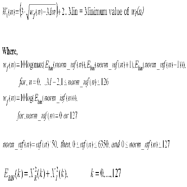
- the weighting function determiner 400 may determine the per-magnitude weighting function W1(n) by using a magnitude of a frequency spectrum bin corresponding to each of the ISF or LSF coefficients.
- the finally derived weighting function W(n) may be determined by Equation 6.
- the LPC coefficient quantizer 500 may include a weighting function determiner 511, a quantization path determiner 513, a first quantization scheme 515, and a second quantization scheme 517. Since the weighting function determiner 511 has been described in FIG. 4, a description thereof is omitted herein.
- the quantization path determiner 513 may determine that one of a plurality of paths, including a first path not using inter-frame prediction and a second path using the inter-frame prediction, is selected as a quantization path of an input signal, based on a criterion before quantization of the input signal.
- the first quantization scheme 515 may quantize the input signal provided from the quantization path determiner 513, when the first path is selected as the quantization path of the input signal.
- the first quantization scheme 515 may include a first quantizer (not shown) for roughly quantizing the input signal and a second quantizer (not shown) for precisely quantizing a quantization error signal between the input signal and an output signal of the first quantizer.
- the second quantization scheme 517 may quantize the input signal provided from the quantization path determiner 513, when the second path is selected as the quantization path of the input signal.
- the first quantization scheme 515 may include an element for performing block-constrained trellis-coded quantization on a predictive error of the input signal and an inter-frame predictive value and an inter-frame prediction element.
- the first quantization scheme 515 and the second quantization scheme 517 are not limited to the current exemplary embodiment and may be implemented by using first and second quantization schemes according to various exemplary embodiments described below, respectively.
- the predictive error calculator 611 may calculate a predictive error in various methods by receiving an inter-frame predictive value p(n), a weighting function w(n), and an LSF coefficient z(n) from which a Direct Current (DC) value is removed.
- an inter-frame predictor (not shown) that is the same as used in a second quantization scheme, i.e., the predictive scheme, may be used.
- any one of an Auto-Regressive (AR) method and a Moving Average (MA) method may be used.
- a signal z(n) of a previous frame for inter-frame prediction may use a quantized value or a non-quantized value.
- a predictive error may be obtained by using or not using the weighting function w(n). Accordingly, the total number of combinations is 8, 4 of which are as follows:
- Equation 7 a weighted AR predictive error using a quantized signal of a previous frame may be represented by Equation 7.
- Equation 8 an AR predictive error using the quantized signal of the previous frame may be represented by Equation 8.
- Equation 9 a weighted AR predictive error using the signal z(n) of the previous frame may be represented by Equation 9.
- Equation 10 an AR predictive error using the signal z(n) of the previous frame may be represented by Equation 10.
- M denotes an order of LSF coefficients and M is usually 16 when a bandwidth of an input speech signal is a WB, and denotes a predictive coefficient of the AR method.
- a quantization scheme may be determined by using a predictive error obtained from the above description.
- a second predictive error may be obtained by using a frame immediately before the previous frame, and a quantization scheme may be determined by using the second predictive error.
- the second predictive error may be represented by Equation 11 below compared with Equation 7.
- the quantization scheme selector 613 determines a quantization scheme of a current frame by using at least one of the predictive error obtained by the predictive error calculator 611 and the coding mode obtained by the coding mode determiner (115 of FIG. 1).
- FIG. 7A is a flowchart illustrating an operation of the quantization path determiner of FIG. 6, according to an exemplary embodiment.
- 0, 1 and 2 may be used as a prediction mode.
- a prediction mode In a prediction mode 0, only a safety-net scheme may be used and in a prediction mode1, only a predictive scheme may be used.
- a prediction mode 2 In a prediction mode 2, the safety-net scheme and the predictive scheme may be switched.
- a signal to be encoded at the prediction mode 0 has a non-stationary characteristic.
- a non-stationary signal has a great variation between neighboring frames. Therefore, if an inter-frame prediction is performed on the non-stationary signal, a prediction error may be larger than an original signal, which results in deterioration in the performance of a quantizer.
- a signal to be encoded at the prediction mode 1 has a stationary characteristic. Because a stationary signal has a small variation between neighboring frames, an inter-frame correlation thereof is high. The optimal performance may be obtained by performing at a prediction mode 2 quantization of a signal in which a non-stationary characteristic and a stationary characteristic are mixed.
- a prediction mode of a current frame is 0, i.e., whether a speech signal of the current frame has a non-stationary characteristic.
- the prediction mode is 0, e.g., when variation of the speech signal of the current frame is great as in the TC mode or the UC mode, since inter-frame prediction is difficult, the safety-net scheme, i.e., the first quantization scheme, may be determined as a quantization path in operation 714.
- the prediction mode is 1, i.e., whether a speech signal of the current frame has a stationary characteristic.
- the prediction mode is 1, since inter-frame prediction performance is excellent, the predictive scheme, i.e., the second quantization scheme, may be determined as the quantization path in operation 715.
- the prediction mode is not 1, it is determined that the prediction mode is 2 to use the first quantization scheme and the second quantization scheme in a switching manner. For example, when the speech signal of the current frame does not have the non-stationary characteristic, i.e., when the prediction mode is 2 in the GC mode or the VC mode, one of the first quantization scheme and the second quantization scheme may be determined as the quantization path by taking a predictive error into account. To do this, it is determined in operation 713 whether a first predictive error between the current frame and a previous frame is greater than a first threshold.
- the first threshold may be defined in advance as an optimal value experimentally or through simulations. For example, in a case of a WB having an order of 16, the first threshold may be set to 2,085,975.
- the first quantization scheme may be determined as the quantization path in operation 714.
- the predictive scheme i.e., the second quantization scheme may be determined as the quantization path in operation 715.
- FIG. 7B is a flowchart illustrating an operation of the quantization path determiner of FIG. 6, according to another exemplary embodiment.
- the safety-net scheme i.e., the first quantization scheme may be determined as the quantization path in operation 735.
- the predictive scheme i.e., the second quantization scheme may be determined as the quantization path in operation 736.
- additional information may be further used besides a prediction mode or a prediction error.
- FIG. 8 is a block diagram of a quantization path determiner according to an exemplary embodiment.
- the quantization path determiner 800 may include a predictive error calculator 811, a spectrum analyzer 813, and a quantization scheme selector 815.
- the predictive error calculator 811 is identical to the predictive error calculator 611 of FIG. 6, a detailed description thereof is omitted.
- the spectrum analyzer 813 may determine signal characteristics of a current frame by analyzing spectrum information. For example, in the spectrum analyzer 813, a weighted distance D between N (N is an integer greater than 1) previous frames and the current frame may be obtained by using spectral magnitude information in the frequency domain, and when the weighted distance is greater than a threshold, i.e., when inter-frame variation is great, the safety-net scheme may be determined as the quantization scheme. Since objects to be compared increases as N increases, complexity increases as N increases.
- the weighted distance D may be obtained using Equation 12 below. To obtain a weighted distance D with low complexity, the current frame may be compared with the previous frames by using only spectral magnitudes around a frequency defined by LSF/ISF. In this case, a mean value, a maximum value, or an intermediate value of magnitudes of M frequency bins around the frequency defined by LSF/ISF may be compared with the previous frames.
- a weighting function Wk(i) may be obtained by Equation 3 described above and is identical to W1(n) of Equation 3.
- Dn n denotes a difference between a previous frame and a current frame.
- the quantization scheme selector 815 may determine a quantization path of the current frame by receiving predictive errors provided from the predictive error calculator 811 and the signal characteristics, a prediction mode, and transmission channel information provided from the spectrum analyzer 813. For example, priorities may be designated to the information input to the quantization scheme selector 815 to be sequentially considered when a quantization path is selected. For example, when a high Frame Error Rate (FER) mode is included in the transmission channel information, a safety-net scheme selection ratio may be set relatively high, or only the safety-net scheme may be selected. The safety-net scheme selection ratio may be variably set by adjusting a threshold related to the predictive errors.
- FER Frame Error Rate
- FIG. 9 illustrates information regarding a channel state transmittable in a network end when a codec service is provided.
- a selection ratio of the predictive scheme as a quantization path is reduced and a selection ratio of the safety-net scheme is increased.
- the safety-net scheme may be used as the quantization path. To do this, a value indicating the channel state by combining a plurality of pieces of transmission channel information is expressed with one or more levels. A high level indicates a state in which a probability of a channel error is high.
- the simplest case is a case where the number of levels is 1, i.e., a case where the channel state is determined as a high FER mode by a high FER mode determiner 911 as shown in FIG. 9. Since the high FER mode indicates that the channel state is very unstable, encoding is performed by using the highest selection ratio of the safety-net scheme or using only the safety-net scheme. When the number of levels is plural, the selection ratio of the safety-net scheme may be set level-by-level.
- an algorithm of determining the high FER mode in the high FER mode determiner 911 may be performed through, for example, 4 pieces of information.
- the 4 pieces of information may be (1) Fast Feedback (FFB) information, which is a Hybrid Automatic Repeat Request (HARQ) feedback transmitted to a physical layer, (2) Slow Feedback (SFB) information, which is fed back from network signaling transmitted to a higher layer than the physical layer, (3) In-band Feedback (ISB) information, which is an in-band signaled from an EVS decoder 913 in a far end, and (4) High Sensitivity Frame (HSF) information, which is selected by an EVS encoder 915 with respect to a specific critical frame to be transmitted in a redundant fashion. While the FFB information and the SFB information are independent to an EVS codec, the ISB information and the HSF information are dependent to the EVS codec and may demand specific algorithms for the EVS codec.
- FFB Fast Feedback
- SFB Hybrid Automatic Repeat Request
- ISB In-band Feedback
- HSF
- the algorithm of determining the channel state as the high FER mode by using the 4 pieces of information may be expressed by means of, for example, the following code as tables 2-4.
- the EVS codec may be ordered to enter into the high FER mode based on analysis information processed with one or more of the 4 pieces of information.
- the analysis information may be, for example, (1) SFBavg derived from a calculated average error rate of Ns frames by using the SFB information, (2) FFBavg derived from a calculated average error rate of Nf frames by using the FFB information, and (3) ISBavg derived from a calculated average error rate of Ni frames by using the ISB information and thresholds Ts, Tf, and Ti of the SFB information, the FFB information, and the ISB information, respectively.
- the EVS codec is determined to enter into the high FER mode based on a result of comparing SFBavg, FFBavg, and ISBavg with the thresholds Ts, Tf, and Ti, respectively. For all conditions, HiOK on whether the each codec commonly support the high FER mode may be checked.
- the high FER mode determiner 911 may be included as a component of the EVS encoder 915 or an encoder of another format. Alternatively, the high FER mode determiner 911 may be implemented in another external device other than the component of the EVS encoder 915 or an encoder of another format.
- FIG. 10 is a block diagram of an LPC coefficient quantizer 1000 according to another exemplary embodiment.
- the LPC coefficient quantizer 1000 may include a quantization path determiner 1010, a first quantization scheme 1030, and a second quantization scheme 1050.
- the quantization path determiner 1010 determines one of a first path including the safety-net scheme and a second path including the predictive scheme as a quantization path of a current frame, based on at least one of a predictive error and a coding mode.
- the first quantization scheme 1030 performs quantization without using the inter-frame prediction when the first path is determined as the quantization path and may include a Multi-Stage Vector Quantizer (MSVQ) 1041 and a Lattice Vector Quantizer (LVQ) 1043.
- the MSVQ 1041 may preferably include two stages.
- the MSVQ 1041 generates a quantization index by roughly performing vector quantization of LSF coefficients from which a DC value is removed.
- the LVQ 1043 generates a quantization index by performing quantization by receiving LSF quantization errors between inverse QLSF coefficients output from the MSVQ 1041 and the LSF coefficients from which a DC value is removed.
- Final QLSF coefficients are generated by adding an output of the MSVQ 1041 and an output of the LVQ 1043 and then adding a DC value to the addition result.
- the first quantization scheme 1030 may implement a very efficient quantizer structure by using a combination of the MSVQ 1041 having excellent performance at a low bit rate though a large size of memory is necessary for a codebook, and the LVQ 1043 that is efficient at the low bit rate with a small size of memory and low complexity.
- the second quantization scheme 1050 performs quantization using the inter-frame prediction when the second path is determined as the quantization path and may include a BC-TCQ 1063, which has an intra-frame predictor 1065, and an inter-frame predictor 1061.
- the inter-frame predictor 1061 may use any one of the AR method and the MA method. For example, a first order AR method is applied. A predictive coefficient is defined in advance, and a vector selected as an optimal vector in a previous frame is used as a past vector for prediction. LSF predictive errors obtained from predictive values of the inter-frame predictor 1061 are quantized by the BC-TCQ 1063 having the intra-frame predictor 1065. Accordingly, a characteristic of the BC-TCQ 1063 having excellent quantization performance with a small size of memory and low complexity at a high bit rate may be maximized.
- an optimal quantizer may be implemented in correspondence with characteristics of an input speech signal.
- 12 bits and 28 bits may be allocated to the MSVQ 1041 and the LVQ 1043 of the first quantization scheme 1030, respectively, except for 1 bit indicating quantization path information.
- 40 bits may be allocated to the BC-TCQ 1063 of the second quantization scheme 1050 except for 1 bit indicating quantization path information.
- Table 5 shows an example in which bits are allocated to a WB speech signal of an 8-KHz band.
- FIG. 11 is a block diagram of an LPC coefficient quantizer according to another exemplary embodiment.
- the LPC coefficient quantizer 1100 shown in FIG. 11 has a structure opposite to that shown in FIG. 10.
- the LPC coefficient quantizer 1100 may include a quantization path determiner 1110, a first quantization scheme 1130, and a second quantization scheme 1150.
- the quantization path determiner 1110 determines one of a first path including the safety-net scheme and a second path including the predictive scheme as a quantization path of a current frame, based on at least one of a predictive error and a prediction mode.
- the first quantization scheme 1130 performs quantization without using the inter-frame prediction when the first path is selected as the quantization path and may include a Vector Quantizer (VQ) 1141 and a BC-TCQ 1143 having an intra-frame predictor 1145.
- VQ 1141 generates a quantization index by roughly performing vector quantization of LSF coefficients from which a DC value is removed.
- the BC-TCQ 1143 generates a quantization index by performing quantization by receiving LSF quantization errors between inverse QLSF coefficients output from the VQ 1141 and the LSF coefficients from which a DC value is removed.
- Final QLSF coefficients are generated by adding an output of the VQ 1141 and an output of the BC-TCQ 1143 and then adding a DC value to the addition result.
- the second quantization scheme 1150 performs quantization using the inter-frame prediction when the second path is determined as the quantization path and may include an LVQ 1163 and an inter-frame predictor 1161.
- the inter-frame predictor 1161 may be implemented the same as or similar to that in FIG. 10. LSF predictive errors obtained from predictive values of the inter-frame predictor 1161 are quantized by the LVQ 1163.
- the BC-TCQ 1143 since the number of bits allocated to the BC-TCQ 1143 is small, the BC-TCQ 1143 has low complexity, and since the LVQ 1163 has low complexity at a high bit rate, quantization may be generally performed with low complexity.
- the LPC coefficient quantizer 1100 when 41 bits are used in the LPC coefficient quantizer 1100 to quantize a speech signal in the GC mode with a WB of 8-KHz, 6 bits and 34 bits may be allocated to the VQ 1141 and the BC-TCQ 1143 of the first quantization scheme 1130, respectively, except for 1 bit indicating quantization path information. In addition, 40 bits may be allocated to the LVQ 1163 of the second quantization scheme 1150 except for 1 bit indicating quantization path information.
- Table 6 shows an example in which bits are allocated to a WB speech signal of an 8-KHz band.
- An optimal index related to the VQ 1141 used in most coding modes may be obtained by searching for an index for minimizing Ewerr(p) of Equation 13.
- Equation 13 w(i) denotes a weighting function determined in the weighting function determiner (313 of FIG. 3), r(i) denotes an input of the VQ 1141, and c(i) denotes an output of the VQ 1141. That is, an index for minimizing weighted distortion between r(i) and c(i) is obtained.
- a distortion measure d(x, y) used in the BC-TCQ 1143 may be represented by Equation 14.
- the weighted distortion may be obtained by applying a weighting function wk to the distortion measure d(x, y) as represented by Equation 15.
- an optimal index may be obtained by obtaining weighted distortion in all stages of the BC-TCQ 1143.
- FIG. 12 is a block diagram of an LPC coefficient quantizer according to another exemplary embodiment.
- the LPC coefficient quantizer 1200 may include a quantization path determiner 1210, a first quantization scheme 1230, and a second quantization scheme 1250.
- the quantization path determiner 1210 determines one of a first path including the safety-net scheme and a second path including the predictive scheme as a quantization path of a current frame, based on at least one of a predictive error and a prediction mode.
- the first quantization scheme 1230 performs quantization without using the inter-frame prediction when the first path is determined as the quantization path and may include a VQ or MSVQ 1241 and an LVQ or TCQ 1243.
- the VQ or MSVQ 1241 generates a quantization index by roughly performing vector quantization of LSF coefficients from which a DC value is removed.
- the LVQ or TCQ 1243 generates a quantization index by performing quantization by receiving LSF quantization errors between inverse QLSF coefficients output from the VQ 1141 and the LSF coefficients from which a DC value is removed.
- Final QLSF coefficients are generated by adding an output of the VQ or MSVQ 1241 and an output of the LVQ or TCQ 1243 and then adding a DC value to the addition result. Since the VQ or MSVQ 1241 has a good bit error rate although the VQ or MSVQ 1241 has high complexity and uses a great amount of memory, the number of stages of the VQ or MSVQ 1241 may increase from 1 to n by taking the overall complexity into account. For example, when only a first stage is used, the VQ or MSVQ 1241 becomes a VQ, and when two or more stages are used, the VQ or MSVQ 1241 becomes an MSVQ. In addition, since the LVQ or TCQ 1243 has low complexity, the LSF quantization errors may be efficiently quantized.
- the second quantization scheme 1250 performs quantization using the inter-frame prediction when the second path is determined as the quantization path and may include an inter-frame predictor 1261 and an LVQ or TCQ 1263.
- the inter-frame predictor 1261 may be implemented the same as or similar to that in FIG. 10. LSF predictive errors obtained from predictive values of the inter-frame predictor 1261 are quantized by the LVQ or TCQ 1263. Likewise, since the LVQ or TCQ 1243 has low complexity, the LSF predictive errors may be efficiently quantized. Accordingly, quantization may be generally performed with low complexity.
- FIG. 13 is a block diagram of an LPC coefficient quantizer according to another exemplary embodiment.
- the LPC coefficient quantizer 1300 may include a quantization path determiner 1310, a first quantization scheme 1330, and a second quantization scheme 1350.
- the quantization path determiner 1310 determines one of a first path including the safety-net scheme and a second path including the predictive scheme as a quantization path of a current frame, based on at least one of a predictive error and a prediction mode.
- the first quantization scheme 1330 performs quantization without using the inter-frame prediction when the first path is determined as the quantization path, and since the first quantization scheme 1330 is the same as that shown in FIG. 12, a description thereof is omitted.
- the second quantization scheme 1350 performs quantization using the inter-frame prediction when the second path is determined as the quantization path and may include an inter-frame predictor 1361, a VQ or MSVQ 1363, and an LVQ or TCQ 1365.
- the inter-frame predictor 1361 may be implemented the same as or similar to that in FIG. 10.
- LSF predictive errors obtained using predictive values of the inter-frame predictor 1361 are roughly quantized by the VQ or MSVQ 1363.
- An error vector between the LSF predictive errors and de-quantized LSF predictive errors output from the VQ or MSVQ 1363 is quantized by the LVQ or TCQ 1365.
- the LSF predictive errors may be efficiently quantized. Accordingly, quantization may be generally performed with low complexity.
- FIG. 14 is a block diagram of an LPC coefficient quantizer according to another exemplary embodiment.
- the LPC coefficient quantizer 1400 has a difference in that a first quantization scheme 1430 includes a BC-TCQ 1443 having an intra-frame predictor 1445 instead of the LVQ or TCQ 1243, and a second quantization scheme 1450 includes a BC-TCQ 1463 having an intra-frame predictor 1465 instead of the LVQ or TCQ 1263.
- 5 bits and 35 bits may be allocated to a VQ 1441 and the BC-TCQ 1443 of the first quantization scheme 1430, respectively, except for 1 bit indicating quantization path information.
- 40 bits may be allocated to the BC-TCQ 1463 of the second quantization scheme 1450 except for 1 bit indicating quantization path information.
- FIG. 15 is a block diagram of an LPC coefficient quantizer according to another exemplary embodiment.
- the LPC coefficient quantizer 1500 shown in FIG. 15 is a concrete example of the LPC coefficient quantizer 1300 shown in FIG. 13, wherein an MSVQ 1541 of a first quantization scheme 1530 and an MSVQ 1563 of a second quantization scheme 1550 have two stages.
- 6+6 12 bits and 28 bits may be allocated to the two-stage MSVQ 1541 and an LVQ 1543 of the first quantization scheme 1530, respectively, except for 1 bit indicating quantization path information.
- 5+5 10 bits and 30 bits may be allocated to the two-stage MSVQ 1563 and an LVQ 1565 of the second quantization scheme 1550, respectively.
- FIGS. 16A and 16B are block diagrams of LPC coefficient quantizers according to other exemplary embodiments.
- the LPC coefficient quantizers 1610 and 1630 shown in FIGS. 16A and 16B, respectively, may be used to form the safety-net scheme, i.e., the first quantization scheme.
- the LPC coefficient quantizer 1610 shown in FIG. 16A may include a VQ 1621 and a TCQ or BC-TCQ 1623 having an intra-frame predictor 1625, and the LPC coefficient quantizer 1630 shown in FIG. 16B may include a VQ or MSVQ 1641 and a TCQ or LVQ 1643.
- the VQ 1621 or the VQ or MSVQ 1641 roughly quantizes the entire input vector with a small number of bits, and the TCQ or BC-TCQ 1623 or the TCQ or LVQ 1643 precisely quantizes LSF quantization errors.
- a List Viterbi Algorithm (LVA) method may be applied for additional performance improvement. That is, since there is room in terms of complexity compared with a switching method when only the first quantization scheme is used, the LVA method achieving the performance improvement by increasing complexity in a search operation may be applied. For example, by applying the LVA method to a BC-TCQ, it may be set so that complexity of an LVA structure is lower than complexity of a switching structure even though the complexity of the LVA structure increases.
- LVA List Viterbi Algorithm
- FIGS. 17A to 17C are block diagrams of LPC coefficient quantizers according to other exemplary embodiments, which particularly have a structure of a BC-TCQ using a weighting function.
- the LPC coefficient quantizer may include a weighting function determiner 1710 and a quantization scheme 1720 including a BC-TCQ 1721 having an intra-frame predictor 1723.
- the LPC coefficient quantizer may include a weighting function determiner 1730 and a quantization scheme 1740 including a BC-TCQ 1743, which has an intra-frame predictor 1745, and an inter-frame predictor 1741.
- a quantization scheme 1740 including a BC-TCQ 1743, which has an intra-frame predictor 1745, and an inter-frame predictor 1741.
- 40 bits may be allocated to the BC-TCQ 1743.
- the LPC coefficient quantizer may include a weighting function determiner 1750 and a quantization scheme 1760 including a BC-TCQ 1763, which has an intra-frame predictor 1765, and a VQ 1761.
- a weighting function determiner 1750 and a quantization scheme 1760 including a BC-TCQ 1763, which has an intra-frame predictor 1765, and a VQ 1761.
- 5 bits and 40 bits may be allocated to the VQ 1761 and the BC-TCQ 1763, respectively.
- FIG. 18 is a block diagram of an LPC coefficient quantizer according to another exemplary embodiment.
- the LPC coefficient quantizer 1800 may include a first quantization scheme 1810, a second quantization scheme 1830, and a quantization path determiner 1850.
- the first quantization scheme 1810 performs quantization without using the inter-frame prediction and may use a combination of an MSVQ 1821 and an LVQ 1823 for quantization performance improvement.
- the MSVQ 1821 may preferably include two stages.
- the MSVQ 1821 generates a quantization index by roughly performing vector quantization of LSF coefficients from which a DC value is removed.
- the LVQ 1823 generates a quantization index by performing quantization by receiving LSF quantization errors between inverse QLSF coefficients output from the MSVQ 1821 and the LSF coefficients from which a DC value is removed.
- Final QLSF coefficients are generated by adding an output of the MSVQ 1821 and an output of the LVQ 1823 and then adding a DC value to the addition result.
- the first quantization scheme 1810 may implement a very efficient quantizer structure by using a combination of the MSVQ 1821 having excellent performance at a low bit rate and the LVQ 1823 that is efficient at the low bit rate.
- the second quantization scheme 1830 performs quantization using the inter-frame prediction and may include a BC-TCQ 1843, which has an intra-frame predictor 1845, and an inter-frame predictor 1841. LSF predictive errors obtained using predictive values of the inter-frame predictor 1841 are quantized by the BC-TCQ 1843 having the intra-frame predictor 1845. Accordingly, a characteristic of the BC-TCQ 1843 having excellent quantization performance at a high bit rate may be maximized.
- the quantization path determiner 1850 determines one of an output of the first quantization scheme 1810 and an output of the second quantization scheme 1830 as a final quantization output by taking a prediction mode and weighted distortion into account.
- an optimal quantizer may be implemented in correspondence with characteristics of an input speech signal. For example, when 43 bits are used in the LPC coefficient quantizer 1800 to quantize a speech signal in the VC mode with a WB of 8-KHz, 12 bits and 30 bits may be allocated to the MSVQ 1821 and the LVQ 1823 of the first quantization scheme 1810, respectively, except for 1 bit indicating quantization path information. In addition, 42 bits may be allocated to the BC-TCQ 1843 of the second quantization scheme 1830 except for 1 bit indicating quantization path information.
- Table 7 shows an example in which bits are allocated to a WB speech signal of an 8-KHz band.
- FIG. 19 is a block diagram of an LPC coefficient quantizer according to another exemplary embodiment.
- the LPC coefficient quantizer 1900 may include a first quantization scheme 1910, a second quantization scheme 1930, and a quantization path determiner 1950.
- the first quantization scheme 1910 performs quantization without using the inter-frame prediction and may use a combination of a VQ 1921 and a BC-TCQ 1923 having an intra-frame predictor 1925 for quantization performance improvement.
- the second quantization scheme 1930 performs quantization using the inter-frame prediction and may include a BC-TCQ 1943, which has an intra-frame predictor 1945, and an inter-frame predictor 1941.
- the quantization path determiner 1950 determines a quantization path by receiving a prediction mode and weighted distortion using optimally quantized values obtained by the first quantization scheme 1910 and the second quantization scheme 1930. For example, it is determined whether a prediction mode of a current frame is 0, i.e., whether a speech signal of the current frame has a non-stationary characteristic. When variation of the speech signal of the current frame is great as in the TC mode or the UC mode, since inter-frame prediction is difficult, the safety-net scheme, i.e., the first quantization scheme 1910, is always determined as the quantization path.
- the quantization path determiner 1950 determines one of the first quantization scheme 1910 and the second quantization scheme 1930 as the quantization path by taking predictive errors into account. To do this, weighted distortion of the first quantization scheme 1910 is considered first of all so that the LPC coefficient quantizer 1900 is robust to frame errors. That is, if a weighted distortion value of the first quantization scheme 1910 is less than a predefined threshold, the first quantization scheme 1910 is selected regardless of a weighted distortion value of the second quantization scheme 1930.
- the first quantization scheme 1910 is selected by considering frame errors in a case of the same weighted distortion value. If the weighted distortion value of the first quantization scheme 1910 is a certain number of times greater than the weighted distortion value of the second quantization scheme 1930, the second quantization scheme 1930 may be selected. The certain number of times may be, for example, set to 1.15. As such, when the quantization path is determined, a quantization index generated by a quantization scheme of the determined quantization path is transmitted.
- the number of prediction modes is 3, it may be implemented to select the first quantization scheme 1910 when the prediction mode is 0, select the second quantization scheme 1930 when the prediction mode is 1, and select one of the first quantization scheme 1910 and the second quantization scheme 1930 when the prediction mode is 2, as the quantization path.
- 2 bits and 34 bits may be allocated to the VQ 1921 and the BC-TCQ 1923 of the first quantization scheme 1910, respectively, except for 1 bit indicating quantization path information.
- 36 bits may be allocated to the BC-TCQ 1943 of the second quantization scheme 1930 except for 1 bit indicating quantization path information.
- Table 8 shows an example in which bits are allocated to a WB speech signal of an 8-KHz band.
- FIG. 20 is a block diagram of an LPC coefficient quantizer according to another exemplary embodiment.
- the LPC coefficient quantizer 2000 may include a first quantization scheme 2010, a second quantization scheme 2030, and a quantization path determiner 2050.
- the first quantization scheme 2010 performs quantization without using the inter-frame prediction and may use a combination of a VQ 2021 and a BC-TCQ 2023 having an intra-frame predictor 2025 for quantization performance improvement.
- the second quantization scheme 2030 performs quantization using the inter-frame prediction and may include an LVQ 2043 and an inter-frame predictor 2041.
- the quantization path determiner 2050 determines a quantization path by receiving a prediction mode and weighted distortion using optimally quantized values obtained by the first quantization scheme 2010 and the second quantization scheme 2030.
- the LPC coefficient quantizer 2000 when 43 bits are used in the LPC coefficient quantizer 2000 to quantize a speech signal in the VC mode with a WB of 8-KHz, 6 bits and 36 bits may be allocated to the VQ 2021 and the BC-TCQ 2023 of the first quantization scheme 2010, respectively, except for 1 bit indicating quantization path information. In addition, 42 bits may be allocated to the LVQ 2043 of the second quantization scheme 2030 except for 1 bit indicating quantization path information.
- Table 9 shows an example in which bits are allocated to a WB speech signal of an 8-KHz band.
- FIG. 21 is a block diagram of quantizer type selector according to an exemplary embodiment.
- the quantizer type selector 2100 shown in FIG. 21 may include a bit-rate determiner 2110, a bandwidth determiner 2130, an internal sampling frequency determiner 2150, and a quantizer type determiner 2107.
- Each of the components may be implemented by at least one processor (e.g., a central processing unit (CPU)) by being integrated in at least one module.
- the quantizer type selector 2100 may be used in a prediction mode 2 in which two quantization schemes are switched.
- the quantizer type selector 2100 may be included as a component of the LPC coefficient quantizer 117 of the sound encoding apparatus 100 of FIG. 1 or a component of the sound encoding apparatus 100 of FIG. 1.
- the bit-rate determiner 2110 determines a coding bit rate of a speech signal.
- the coding bit rate may be determined for all frames or in a frame unit.
- a quantizer type may be changed depending on the coding bit rate.
- the bandwidth determiner 2130 determines a bandwidth of the speech signal.
- the quantizer type may be changed depending on the bandwidth of the speech signal.
- the internal sampling frequency determiner 2150 determines an internal sampling frequency based on an upper limit of a bandwidth used in a quantizer.
- a WB i.e., the WB, an SWB, or an FB
- the internal sampling frequency varies according to whether the upper limit of the coding bandwidth is 6.4 KHz or 8 KHz. If the upper limit of the coding bandwidth is 6.4 KHz, the internal sampling frequency is 12.8 KHz, and if the upper limit of the coding bandwidth is 8 KHz, the internal sampling frequency is 16 KHz.
- the upper limit of the coding bandwidth is not limited thereto.
- the quantizer type determiner 2107 selects one of an open-loop and a closed-loop as the quantizer type by receiving an output of the bit-rate determiner 2110, an output of the bandwidth determiner 2130, and an output of the internal sampling frequency determiner 2150.
- the quantizer type determiner 2107 may select the open-loop as the quantizer type when the coding bit rate is greater than a predetermined reference value, the bandwidth of the voice signal is equal to or wider than the WB, and the internal sampling frequency is 16 KHz. Otherwise, the closed-loop may be selected as the quantizer type.
- FIG. 22 is a flowchart illustrating a method of selecting a quantizer type, according to an exemplary embodiment.
- operation 2201 it is determined whether a bit rate is greater than a reference value.
- the reference value is set to 16.4 Kbps in FIG. 22 but is not limited thereto.
- a closed-loop type is selected in operation 2209.
- the sound decoding apparatus 2300 may include a parameter decoder 2311, an LPC coefficient de-quantizer 2313, a variable mode decoder 2315, and a post-processor 2319.
- the sound decoding apparatus 2300 may further include an error restorer 2317.
- Each of the components of the sound decoding apparatus 2300 may be implemented by at least one processor (e.g., a central processing unit (CPU)) by being integrated in at least one module.
- processor e.g., a central processing unit (CPU)
- the variable mode decoder 2315 may generate a synthesized signal by decoding the LPC coefficients generated by the LPC coefficient de-quantizer 2313.
- the variable mode decoder 2315 may perform the decoding in correspondence with the coding modes as shown in FIGS. 2A to 2D according to encoding apparatuses corresponding to decoding apparatuses.
- the error restorer 2317 may restore or conceal a current frame of a speech signal when errors occur in the current frame as a result of the decoding of the variable mode decoder 2315.
- the ISF/LSF de-quantizer 2411 may generate decoded ISF or LSF coefficients by de-quantizing quantized ISF or LSF coefficients, quantized ISF or LSF quantization errors, or quantized ISF or LSF predictive errors included in LPC parameters in correspondence with quantization path information included in a bitstream.
- the de-quantization path determiner 2511 may provide LPC parameters to one of the first de-quantization scheme 2513 and the second de-quantization scheme 2515 based on quantization path information included in a bitstream.
- the quantization path information may be represented by 1 bit.
- Final decoded LSF coefficients are generated by adding the de-quantized LSF coefficients obtained by the MSVQ 2611 and the de-quantized LSF quantization errors obtained by the LVQ 2613 and then adding a mean value, which is a predetermined DC value, to the addition result.
- the speaker 3070 may output the restored sound generated by the decoding module 3030 to the outside.
- FIG. 31 is a block diagram of an electronic device including an encoding module and a decoding module, according to an exemplary embodiment.
- Each of the electronic devices 2900, 3000, and 3100 shown in FIGS. 29, 30, and 31 may include a voice communication only terminal, such as a telephone or a mobile phone, a broadcasting or music only device, such as a TV or an MP3 player, or a hybrid terminal device of a voice communication only terminal and a broadcasting or music only device but are not limited thereto.
- a voice communication only terminal such as a telephone or a mobile phone
- a broadcasting or music only device such as a TV or an MP3 player
- a hybrid terminal device of a voice communication only terminal and a broadcasting or music only device but are not limited thereto.
- each of the electronic devices 2900, 3000, and 3100 may be used as a client, a server, or a transducer displaced between a client and a server.
Landscapes
- Engineering & Computer Science (AREA)
- Physics & Mathematics (AREA)
- Computational Linguistics (AREA)
- Signal Processing (AREA)
- Health & Medical Sciences (AREA)
- Audiology, Speech & Language Pathology (AREA)
- Human Computer Interaction (AREA)
- Acoustics & Sound (AREA)
- Multimedia (AREA)
- Spectroscopy & Molecular Physics (AREA)
- Algebra (AREA)
- General Physics & Mathematics (AREA)
- Mathematical Analysis (AREA)
- Mathematical Optimization (AREA)
- Mathematical Physics (AREA)
- Pure & Applied Mathematics (AREA)
- Theoretical Computer Science (AREA)
- Quality & Reliability (AREA)
- Compression, Expansion, Code Conversion, And Decoders (AREA)
- Compression Or Coding Systems Of Tv Signals (AREA)
Abstract
Description
| Coding Mode | Quantization Scheme | Structure |
| UC, NB/WB | Satety-net | VQ + BC-TCQ |
| VC, NB/WB | Satety-net Predictive | VQ + BC-TCQInter-frame prediction + BC-TCQ with intra-frame prediction |
| GC, NB/WB | Satety-net Predictive | VQ + BC-TCQInter-frame prediction + BC-TCQ with intra-frame prediction |
| TC, NB/WB | Satety-net | VQ + BC-TCQ |


| SFBavg: Average error rate over Ns framesFFBavg: Average error rate over Nf framesISBavg: Average error rate over Ni framesTs: Threshold for slow feedback error rateTf: Threshold for fast feedback error rateTi: Threshold for inband feedback error rate |
| Ns = 100 Nf = 10 Ni = 100 Ts = 20 Tf = 2 Ti = 20 |
| Loop over each frame {HFM = 0;IF((HiOK) AND SFBavg > Ts) THEN HFM = 1;ELSE IF ((HiOK) AND FFBavg > Tf) THEN HFM = 1;ELSE IF ((HiOK) AND ISBavg > TI) THEN HFM = 1;ELSE IF ((HiOK) AND (HSF = 1) THEN HFM = 1;Update SFBavg;Update FFBavg;Update ISBavg;} |
| Coding mode | LSF/ISF quantization scheme | MSVQ-LVQ [bits] | BC-TCQ [bits] |
| GC, WB | Safety-netPredictive | 40/41- | -40/41 |
| TC, WB | Safety-net | 41 | - |
| Coding mode | LSF/ISF quantization scheme | MSVQ-LVQ [bits] | BC-TCQ [bits] |
| GC, WB | Safety-netPredictive | -40/41 | 40/41- |
| TC, WB | Safety-net | - | 41 |
| Coding mode | LSF/ISF quantization scheme | MSVQ-LVQ [bits] | BC-TCQ [bits] |
| VC, WB | Safety-netPredictive | 43- | -43 |
| Coding mode | LSF/ISF quantization scheme | Number of used bits |
| VC, WB | Safety-netPredictive | 4343 |
| GC, WB | Safety-netPredictive | 3737 |
| TC, WB | Safety-net | 44 |
| Coding mode | LSF/ISF quantization scheme | MSVQ-LVQ [bits] | BC-TCQ [bits] |
| VC, WB | Safety-netPredictive | -43 | 43- |
Claims (40)
- A quantizing apparatus comprising:a quantization path determination unit that determines one of a plurality of paths comprising a first path not using inter-frame prediction and a second path using the inter-frame prediction, as a quantization path of an input signal, based on a criterion before quantization of the input signal;a first quantization unit that quantizes the input signal, if the first path is determined as the quantization path of the input signal; anda second quantization unit that quantizesthe input signal, if the second path is determined as the quantization path of the input signal.
- The quantizing apparatus of claim 1, wherein the first quantization unit comprises a first quantizer to roughly quantize the input signal and a second quantizer to precisely quantize a quantization error signal between the input signal and an output signal of the first quantizer.
- The quantizing apparatus of claim 1, wherein the first quantization unit comprises a Multi-Stage Vector Quantizer (MSVQ) for quantizing the input signal, and a Lattice Multi-Stage Vector Quantizer (LVQ) for quantizing an error signal indicating an error determined between the input signal and an output signal of the MSVQ.
- The quantizing apparatus of claim 1, wherein the second quantization unit comprises an inter-frame predictor that performs the inter-frame prediction of the input signal, and a Block-Constrained Trellis-Coded Quantizer (BC-TCQ) having an intra-frame predictor that quantizes predictive errors.
- The quantizing apparatus of claim 4, wherein the BC-TCQ determines a quantization index by using weighted distortion.
- The quantizing apparatus of claim 1, wherein the criterion comprises at least one of a prediction mode and a predictive error according to a characteristic of the input signal.
- The quantizing apparatus of claim 6, wherein the criterion further comprises a transmission channel state.
- The quantizing apparatus of claim 6, wherein the criterion further comprises at least one of a coding bit rate, a bandwidth of the input signal and an internal sampling frequency.
- The quantizing apparatus of claim 6, wherein the predictive error is obtained by using a signal of a current frame, a signal of a previous frame, and a weighting function related to an importance of the input signal.
- The quantizing apparatus of claim 9, wherein the weighting function is determined by using at least one of a frequency band of the input signal, a coding mode, and spectrum analysis information.
- The quantizing apparatus of claim 6, wherein, when the input signal is non-stationary, the first path is selected.
- The quantizing apparatus of claim 6, wherein, when the input signal is stationary, one of the first path and the second path is selected based on the predictive error.
- The quantizing apparatus of claim 1, wherein the quantization path determination unit performs:determining a prediction mode of the input signal;selecting the first path or the second path as the quantization path of the input signal by using the prediction mode of the input signal;if the quantization path of the input signal is not determined by using the prediction mode of the input signal, comparing a first predictive error obtained from a current frame and a previous frame with a first threshold; andif the first predictive error is greater than or equal to the first threshold, selecting the first path as the quantization path of the input signal, and if the first predictive error is not greater than or equal to the first threshold, selecting the second path as the quantization path of the input signal.
- The quantizing apparatus of claim 13, wherein the quantization path determination unit further performs:if an error occurs in the previous frame, comparing a second predictive error obtained from the current frame and the previous frame with a second threshold; andif the second predictive error is greater than or equal to the second threshold, selecting the first path as the quantization path of the input signal, and if the second predictive error is not greater than or equal to the second threshold, selecting the second path as the quantization path of the input signal.
- A quantizing apparatus comprising:a quantization path determination unit that determines one of a plurality of paths, comprising a first path not using inter-frame prediction and a second path using the inter-frame prediction, as a quantization path of Linear Predictive Coding (LPC) coefficients based on a criterion before quantization of the LPC coefficients;a first quantization unit that quantizes the LPC coefficients, if the first path is determined as the quantization path of the LPC coefficients; anda second quantization unit that quantizes the LPC coefficients, if the second path is determined as the quantization path of the LPC coefficients,wherein the first quantization unit comprises a Multi-Stage Vector Quantizer (MSVQ) for quantizing the LPC coefficients, and a Lattice Multi-Stage Vector Quantizer (LVQ) for quantizing errors between the LPC coefficients and an output of the MSVQ, andthe second quantization unit comprises an inter-frame predictor for performing the inter-frame prediction of the LPC coefficients, and a Block-Constrained Trellis-Coded Quantizer (BC-TCQ) having an intra-frame predictor for quantizing predictive errors.
- A de-quantizing apparatus comprising:a de-quantization path determination unit that determines one of a plurality of paths comprising a first path not using inter-frame prediction and a second path using the inter-frame prediction, as a de-quantization path of Linear Predictive Coding (LPC) parameters based on quantization path information included in a bitstream;a first de-quantization unit that de-quantizes the LPC parameters, if the first path is determined as the de-quantization path of the LPC parameters; anda second de-quantization unit that de-quantizes the LPC parameters, if the second path is selected as the de-quantization path of the LPC parameters,wherein the quantization path information is determined based on a criterion before quantization of an input signal in an encoding end.
- The de-quantizing apparatus of claim 16, wherein the first de-quantization unit comprises a first de-quantizer that roughly de-quantizes the LPC parameters and a second de-quantizer that precisely de-quantizes the LPC parameters.
- A de-quantizing apparatus comprising:a de-quantization path determination unit that determines one of a plurality of paths comprising a first path not using inter-frame prediction and a second path using the inter-frame prediction, as a de-quantization path of Linear Predictive Coding (LPC) parameters based on quantization path information included in a bitstream;a first de-quantization unit that de-quantizes the LPC parameters, if the first path is determined as the de-quantization path of the LPC parameters; anda second de-quantization unit that de-quantizes the LPC parameters, if the second path is determined as the de-quantization path of the LPC parameters,wherein the first de-quantization unit comprises a Multi-Stage Vector Quantizer (MSVQ) that de-quantizes the LPC parameters by using a first codebook index, and a Lattice Multi-Stage Vector Quantizer (LVQ) that de-quantizes the LPC parameters by using a second codebook index, andthe second de-quantization unit comprises a Block-Constrained Trellis-Coded Quantizer (BC-TCQ) having an intra-frame predictor that de-quantizes the LPC parameters by using a third codebook index and an inter-frame predictor.
- An encoding apparatus comprising:a coding mode determination unit that determines a coding mode of an input signal;a quantization unit that determines one of a plurality of paths comprising a first path not using inter-frame prediction and a second path using the inter-frame prediction, as a quantization path of the input signal based on a criterion before quantization of the input signal and quantize the input signal by using one of a first quantization scheme and a second quantization scheme according to the determined quantization path;a variable mode encoding unit that encodes the quantized input signal in the coding mode; anda parameter encoding unit that generates a bitstream including one of a result quantized in the first quantization unit and a result quantized in the second quantization unit, the coding mode of the input signal, and path information related to the quantization of the input signal.
- A decoding apparatus comprising:a parameter decoding unit that decodes Linear Predictive Coding (LPC) parameters and a coding mode included in a bitstream;a de-quantization unit that de-quantizes the decoded LPC parameters by using one of a first de-quantization scheme not using inter-frame prediction and a second de-quantization scheme using the inter-frame prediction based on quantization path information included in the bitstream; anda variable mode decoding unit that decodes the de-quantized LPC parameters in the decoded coding mode,wherein the quantization path information is determined based on a criterion before quantization of an input signal in an encoding end.
- The decoding apparatus of claim 20, wherein the first de-quantization scheme comprises a Multi-Stage Vector Quantizer (MSVQ) that de-quantizes the LPC parameters by using a first codebook index, and a Lattice Multi-Stage Vector Quantizer (LVQ) that de-quantizes the LPC parameters by using a second codebook index.
- The decoding apparatus of claim 20, wherein the second de-quantization scheme comprises a Block-Constrained Trellis-Coded Quantizer (BC-TCQ) having an intra-frame predictor that de-quantizes the LPC parameters by using a third codebook index and an inter-frame predictor.
- A decoding apparatus comprising:a parameter decoding unit that decodes Linear Predictive Coding (LPC) parameters and a coding mode included in a bitstream;a de-quantization unit that de-quantizes the decoded LPC parameters by using one of a first de-quantization scheme not using inter-frame prediction and a second de-quantization scheme using the inter-frame prediction based on quantization path information included in the bitstream; anda variable mode decoding unit that decodes the de-quantized LPC parameters in the decoded coding mode,wherein the first de-quantization scheme comprises a Multi-Stage Vector Quantizer (MSVQ) that de-quantizes the LPC parameters by using a first codebook index, and a Lattice Multi-Stage Vector Quantizer (LVQ) that de-quantizes the LPC parameters by using a second codebook index, andthe second de-quantization scheme comprises a Block-Constrained Trellis-Coded Quantizer (BC-TCQ) having an intra-frame predictor that de-quantizes the LPC parameters by using a third codebook index and an inter-frame predictor.
- A quantizing apparatus comprising:a first quantization unit that quantizes an input signal by using a first quantization scheme not using inter-frame prediction;a second quantization unit that quantizes the input signal by using a second quantization scheme using the inter-frame prediction; anda quantization path determination unit that selects one of outputs of the first quantization scheme and the second quantization scheme by using quantized distortion obtained by the first quantization scheme and quantized distortion obtained by the second quantization scheme,wherein the first quantization scheme comprises a Multi-Stage Vector Quantizer (MSVQ) that quantizes the input signal, and a Lattice Multi-Stage Vector Quantizer (LVQ) that quantizes an error signal between the input signal and an output signal of the MSVQ, andthe second quantization scheme comprises an inter-frame predictor that performs the inter-frame prediction of the input signal, and a Block-Constrained Trellis-Coded Quantizer (BC-TCQ) having an intra-frame predictor that quantizes predictive errors.
- An electronic device comprising:a communication unit that receives at least one of a sound signal and an encoded bitstream, or that transmits at least one of an encoded sound signal and a restored sound; andan encoding module that selects one of a plurality of paths comprising a first path not using inter-frame prediction and a second path using the inter-frame prediction, as a quantization path of the received sound signal based on a criterion before quantization of the received sound signal, quantizes the received sound signal by using one of a first quantization scheme and a second quantization scheme according to the selected quantization path, and encodes the quantized sound signal in a coding mode.
- The electronic device of claim 25, wherein the first quantization scheme comprises a first quantizer that roughly quantizes the received sound signal, and a second quantizer that precisely quantizes a quantization error signal between the received sound signal and an output signal of the first quantizer.
- The electronic device of claim 25, wherein the first quantization scheme comprises a Multi-Stage Vector Quantizer (MSVQ) that quantizes the received sound signal, and a Lattice Multi-Stage Vector Quantizer (LVQ) that quantizes an error signal between the received sound signal and an output signal of the MSVQ.
- The electronic device of claim 25, wherein the second quantization scheme comprises an inter-frame predictor that performs the inter-frame prediction of the received sound signal, and a Block-Constrained Trellis-Coded Quantizer (BC-TCQ) having an intra-frame predictor that quantizes predictive errors.
- An electronic device comprising:a communication unit that receives at least one of a sound signal and an encoded bitstream, or that transmits at least one of an encoded sound signal and a restored sound; anda decoding module that decodes Linear Predictive Coding (LPC) parameters and a coding mode included in the bitstream, de-quantizes the decoded LPC parameters by using one of a first de-quantization scheme not using inter-frame prediction and a second de-quantization scheme using the inter-frame prediction based on path information included in the bitstream, and decodes the de-quantized LPC parameters in the decoded coding mode,wherein the path information is determined based on a criterion before quantization of the sound signal in an encoding end.
- The electronic device of claim 29, wherein the first de-quantization scheme comprises a first de-quantizer that roughly de-quantizes the LPC parameters, and a second de-quantizer that precisely de-quantizes the LPC parameters.
- The electronic device of claim 29, wherein the first de-quantization scheme comprises a Multi-Stage Vector Quantizer (MSVQ) that de-quantizes the LPC parameters by using a first codebook index, and a Lattice Multi-Stage Vector Quantizer (LVQ) that de-quantizes the LPC parameters by using a second codebook index.
- The electronic device of claim 29, wherein the second de-quantization scheme comprises a Block-Constrained Trellis-Coded Quantizer (BC-TCQ) having an intra-frame predictor that de-quantizes the LPC parameters by using a third codebook index and an inter-frame predictor.
- An electronic device comprising:a communication unit that receives at least one of a sound signal and an encoded bitstream, or that transmits at least one of an encoded sound signal and a restored sound;an encoding module that selects one of a plurality of paths comprising a first path not using inter-frame prediction and a second path using the inter-frame prediction, as a quantization path of the received sound signal based on a criterion before quantization of the received sound signal, quantizes the received sound signal by using one of a first quantization scheme and a second quantization scheme according to the selected quantization path, and encodes the quantized sound signal in a coding mode; anda decoding module that decodes Linear Predictive Coding (LPC) parameters and a coding mode included in the bitstream, de-quantizes the decoded LPC parameters by using one of a first de-quantization scheme not using the inter-frame prediction and a second de-quantization scheme using the inter-frame prediction based on path information included in the bitstream, and decodes the de-quantized LPC parameters in the decoded coding mode.
- The electronic device of claim 33, wherein the first quantization scheme comprises a first quantizer that roughly quantizes the received sound signal and a second quantizer that precisely quantizes a quantization error signal between the received sound signal and an output signal of the first quantizer.
- An electronic device comprising:a communication unit that receives at least one of a sound signal and an encoded bitstream, or that transmits at least one of an encoded sound signal and a restored sound; andan encoding module that quantizes the received sound signal by selecting one of a first quantization scheme not using an inter-frame prediction and a second quantization scheme using the inter-frame prediction, according to path information determined in consideration of at least one of a prediction mode, a predictive error and a transmission channel state, and that encodes the quantized sound signal in a coding mode.
- The electronic device of claim 35, wherein the first quantization scheme comprises a first quantizer that roughly quantizes the received sound signal and a second quantizer that precisely quantizes a quantization error signal between the received sound signal and an output signal of the first quantizer.
- An electronic device comprising:a communication unit that receives at least one of a sound signal and an encoded bitstream, or that transmits at least one of an encoded sound signal and a restored sound; anda decoding module that decodes Linear Predictive Coding (LPC) parameters and a coding mode included in the bitstream, de-quantizes the decoded LPC parameters by using one of a first de-quantization scheme not using inter-frame prediction and a second de-quantization scheme using the inter-frame prediction based on path information included in the bitstream, and decodes the de-quantized LPC parameters in the decoded coding mode,wherein the path information is determined in consideration of at least one of a prediction mode, a predictive error and a transmission channel state in an encoding end.
- The electronic device of claim 37, wherein the first de-quantization scheme comprises a first de-quantizer that roughly de-quantizes the LPC parameters and a second de-quantizer that precisely de-quantizes the LPC parameters.
- An electronic device comprising:a communication unit that receives at least one of a sound signal and an encoded bitstream, or that transmits at least one of an encoded sound signal and a restored sound;an encoding module that quantizes the received sound signal by selecting one of a first quantization scheme not using an inter-frame prediction and a second quantization scheme using the inter-frame prediction, according to path information determined in consideration of at least one of a prediction mode, a predictive error and a transmission channel state, and that encodes the quantized sound signal in a coding mode; anda decoding module that decodes Linear Predictive Coding (LPC) parameters and a coding mode included in the bitstream, de-quantizes the decoded LPC parameters by using one of a first de-quantization scheme not using inter-frame prediction and a second de-quantization scheme using the inter-frame prediction based on path information included in the bitstream, and decodes the de-quantized LPC parameters in the decoded coding mode.
- The electronic device of claim 39, wherein the first quantization scheme comprises a first quantizer that roughly quantizes the received sound signal and a second quantizer that precisely quantizes a quantization error signal between the received sound signal and an output signal of the first quantizer.
Priority Applications (13)
| Application Number | Priority Date | Filing Date | Title |
|---|---|---|---|
| CA2833868A CA2833868C (en) | 2011-04-21 | 2012-04-23 | Apparatus for quantizing linear predictive coding coefficients, sound encoding apparatus, apparatus for de-quantizing linear predictive coding coefficients, sound decoding apparatus, and electronic device therefor |
| CN201280030913.7A CN103620675B (en) | 2011-04-21 | 2012-04-23 | Device for quantizing linear predictive coding coefficients, audio coding device, device for dequantizing linear predictive coding coefficients, audio decoding device and electronic device thereof |
| EP12773932.4A EP2700072A4 (en) | 2011-04-21 | 2012-04-23 | APPARATUS FOR QUANTIFYING LINEAR PREDICTIVE ENCODING COEFFICIENTS, SOUND ENCODING APPARATUS, APPARATUS FOR DETERMINING LINEAR PREDICTIVE ENCODING COEFFICIENTS, SOUND DECODING APPARATUS, AND ELECTRONIC DEVICE RELATING THERETO |
| JP2014506340A JP6178304B2 (en) | 2011-04-21 | 2012-04-23 | Quantizer |
| AU2012246798A AU2012246798B2 (en) | 2011-04-21 | 2012-04-23 | Apparatus for quantizing linear predictive coding coefficients, sound encoding apparatus, apparatus for de-quantizing linear predictive coding coefficients, sound decoding apparatus, and electronic device therefor |
| BR122021000241-0A BR122021000241B1 (en) | 2011-04-21 | 2012-04-23 | LINEAR PREDICTIVE CODING COEFFICIENT QUANTIZATION APPARATUS |
| BR112013027092-6A BR112013027092B1 (en) | 2011-04-21 | 2012-04-23 | QUANTIZATION METHOD FOR AN INPUT SIGNAL INCLUDING AT LEAST ONE OF A VOICE FEATURE AND AN AUDIO FEATURE IN AN ENCODING DEVICE, AND DECODING APPARATUS FOR AN ENCODED SIGNAL INCLUDING AT LEAST ONE OF A VOICE CHARACTERISTIC AUDIO IN A DECODING DEVICE |
| MX2013012301A MX2013012301A (en) | 2011-04-21 | 2012-04-23 | Apparatus for quantizing linear predictive coding coefficients, sound encoding apparatus, apparatus for de-quantizing linear predictive coding coefficients, sound decoding apparatus, and electronic device therefor. |
| CN201510818721.8A CN105244034B (en) | 2011-04-21 | 2012-04-23 | Quantization method and decoding method and apparatus for speech signal or audio signal |
| RU2013151798A RU2606552C2 (en) | 2011-04-21 | 2012-04-23 | Device for quantization of linear predictive coding coefficients, sound encoding device, device for dequantization of linear predictive coding coefficients, sound decoding device and electronic device to this end |
| SG2013078555A SG194580A1 (en) | 2011-04-21 | 2012-04-23 | Apparatus for quantizing linear predictive coding coefficients, sound encoding apparatus, apparatus for de-quantizing linear predictive coding coefficients, sound decoding apparatus, and electronic device therefor |
| ZA2013/08710A ZA201308710B (en) | 2011-04-21 | 2013-11-20 | Apparatus for quantizing linear predictive coding coefficients, sound encoding apparatus, apparatus for de-quantizing linear predictive coefficients, sound decoding apparatus, and electronic device therefor |
| AU2017200829A AU2017200829B2 (en) | 2011-04-21 | 2017-02-07 | Apparatus for quantizing linear predictive coding coefficients, sound encoding apparatus, apparatus for de-quantizing linear predictive coding coefficients, sound decoding apparatus, and electronic device therefor |
Applications Claiming Priority (4)
| Application Number | Priority Date | Filing Date | Title |
|---|---|---|---|
| US201161477797P | 2011-04-21 | 2011-04-21 | |
| US61/477,797 | 2011-04-21 | ||
| US201161507744P | 2011-07-14 | 2011-07-14 | |
| US61/507,744 | 2011-07-14 |
Publications (2)
| Publication Number | Publication Date |
|---|---|
| WO2012144877A2 true WO2012144877A2 (en) | 2012-10-26 |
| WO2012144877A3 WO2012144877A3 (en) | 2013-03-21 |
Family
ID=47022011
Family Applications (1)
| Application Number | Title | Priority Date | Filing Date |
|---|---|---|---|
| PCT/KR2012/003127 Ceased WO2012144877A2 (en) | 2011-04-21 | 2012-04-23 | Apparatus for quantizing linear predictive coding coefficients, sound encoding apparatus, apparatus for de-quantizing linear predictive coding coefficients, sound decoding apparatus, and electronic device therefor |
Country Status (15)
| Country | Link |
|---|---|
| US (3) | US8977543B2 (en) |
| EP (1) | EP2700072A4 (en) |
| JP (2) | JP6178304B2 (en) |
| KR (2) | KR101863687B1 (en) |
| CN (3) | CN105244034B (en) |
| AU (2) | AU2012246798B2 (en) |
| BR (2) | BR122021000241B1 (en) |
| CA (1) | CA2833868C (en) |
| MX (1) | MX2013012301A (en) |
| MY (2) | MY190996A (en) |
| RU (2) | RU2606552C2 (en) |
| SG (1) | SG194580A1 (en) |
| TW (2) | TWI672692B (en) |
| WO (1) | WO2012144877A2 (en) |
| ZA (1) | ZA201308710B (en) |
Cited By (5)
| Publication number | Priority date | Publication date | Assignee | Title |
|---|---|---|---|---|
| US8977543B2 (en) | 2011-04-21 | 2015-03-10 | Samsung Electronics Co., Ltd. | Apparatus for quantizing linear predictive coding coefficients, sound encoding apparatus, apparatus for de-quantizing linear predictive coding coefficients, sound decoding apparatus, and electronic device therefore |
| US8977544B2 (en) | 2011-04-21 | 2015-03-10 | Samsung Electronics Co., Ltd. | Method of quantizing linear predictive coding coefficients, sound encoding method, method of de-quantizing linear predictive coding coefficients, sound decoding method, and recording medium and electronic device therefor |
| KR20160145561A (en) * | 2014-03-28 | 2016-12-20 | 삼성전자주식회사 | Method and apparatus for quantizing linear predictive coding coefficients and method and apparatus for dequantizing linear predictive coding coefficients |
| RU2607260C1 (en) * | 2013-02-21 | 2017-01-10 | Квэлкомм Инкорпорейтед | Systems and methods for determining set of interpolation coefficients |
| KR20170007280A (en) * | 2014-05-07 | 2017-01-18 | 삼성전자주식회사 | Method and device for quantizing linear predictive coefficient, and method and device for dequantizing same |
Families Citing this family (31)
| Publication number | Priority date | Publication date | Assignee | Title |
|---|---|---|---|---|
| KR101747917B1 (en) | 2010-10-18 | 2017-06-15 | 삼성전자주식회사 | Apparatus and method for determining weighting function having low complexity for lpc coefficients quantization |
| US9495968B2 (en) | 2013-05-29 | 2016-11-15 | Qualcomm Incorporated | Identifying sources from which higher order ambisonic audio data is generated |
| EP3614381A1 (en) | 2013-09-16 | 2020-02-26 | Samsung Electronics Co., Ltd. | Signal encoding method and device and signal decoding method and device |
| CN103685093B (en) * | 2013-11-18 | 2017-02-01 | 北京邮电大学 | Explicit feedback method and device |
| US9922656B2 (en) * | 2014-01-30 | 2018-03-20 | Qualcomm Incorporated | Transitioning of ambient higher-order ambisonic coefficients |
| US9502045B2 (en) | 2014-01-30 | 2016-11-22 | Qualcomm Incorporated | Coding independent frames of ambient higher-order ambisonic coefficients |
| EP2922054A1 (en) | 2014-03-19 | 2015-09-23 | Fraunhofer-Gesellschaft zur Förderung der angewandten Forschung e.V. | Apparatus, method and corresponding computer program for generating an error concealment signal using an adaptive noise estimation |
| EP2922056A1 (en) | 2014-03-19 | 2015-09-23 | Fraunhofer-Gesellschaft zur Förderung der angewandten Forschung e.V. | Apparatus, method and corresponding computer program for generating an error concealment signal using power compensation |
| EP2922055A1 (en) | 2014-03-19 | 2015-09-23 | Fraunhofer-Gesellschaft zur Förderung der angewandten Forschung e.V. | Apparatus, method and corresponding computer program for generating an error concealment signal using individual replacement LPC representations for individual codebook information |
| US10770087B2 (en) | 2014-05-16 | 2020-09-08 | Qualcomm Incorporated | Selecting codebooks for coding vectors decomposed from higher-order ambisonic audio signals |
| CN105225670B (en) | 2014-06-27 | 2016-12-28 | 华为技术有限公司 | A kind of audio coding method and device |
| KR102742778B1 (en) * | 2014-07-28 | 2024-12-16 | 삼성전자주식회사 | Signal encoding method and apparatus and signal decoding method and apparatus |
| CN107408390B (en) * | 2015-04-13 | 2021-08-06 | 日本电信电话株式会社 | Linear prediction encoding device, linear prediction decoding device, their method, and recording medium |
| RU2727794C1 (en) | 2017-05-18 | 2020-07-24 | Фраунхофер-Гезелльшафт Цур Фердерунг Дер Ангевандтен Форшунг Е.Ф. | Control network device |
| EP3483878A1 (en) | 2017-11-10 | 2019-05-15 | Fraunhofer-Gesellschaft zur Förderung der angewandten Forschung e.V. | Audio decoder supporting a set of different loss concealment tools |
| EP3483882A1 (en) * | 2017-11-10 | 2019-05-15 | Fraunhofer-Gesellschaft zur Förderung der angewandten Forschung e.V. | Controlling bandwidth in encoders and/or decoders |
| EP3483886A1 (en) | 2017-11-10 | 2019-05-15 | Fraunhofer-Gesellschaft zur Förderung der angewandten Forschung e.V. | Selecting pitch lag |
| WO2019091576A1 (en) | 2017-11-10 | 2019-05-16 | Fraunhofer-Gesellschaft zur Förderung der angewandten Forschung e.V. | Audio encoders, audio decoders, methods and computer programs adapting an encoding and decoding of least significant bits |
| EP3483884A1 (en) | 2017-11-10 | 2019-05-15 | Fraunhofer-Gesellschaft zur Förderung der angewandten Forschung e.V. | Signal filtering |
| EP3483883A1 (en) | 2017-11-10 | 2019-05-15 | Fraunhofer-Gesellschaft zur Förderung der angewandten Forschung e.V. | Audio coding and decoding with selective postfiltering |
| EP3483879A1 (en) | 2017-11-10 | 2019-05-15 | Fraunhofer-Gesellschaft zur Förderung der angewandten Forschung e.V. | Analysis/synthesis windowing function for modulated lapped transformation |
| EP3483880A1 (en) | 2017-11-10 | 2019-05-15 | Fraunhofer-Gesellschaft zur Förderung der angewandten Forschung e.V. | Temporal noise shaping |
| WO2019091573A1 (en) | 2017-11-10 | 2019-05-16 | Fraunhofer-Gesellschaft zur Förderung der angewandten Forschung e.V. | Apparatus and method for encoding and decoding an audio signal using downsampling or interpolation of scale parameters |
| JP7196201B2 (en) | 2018-06-04 | 2022-12-26 | コーセプト セラピューティクス, インコーポレイテッド | pyrimidine cyclohexenyl glucocorticoid receptor modulator |
| CN113348507B (en) * | 2019-01-13 | 2025-02-21 | 华为技术有限公司 | High-resolution audio codec |
| WO2020253941A1 (en) * | 2019-06-17 | 2020-12-24 | Fraunhofer-Gesellschaft zur Förderung der angewandten Forschung e.V. | Audio encoder with a signal-dependent number and precision control, audio decoder, and related methods and computer programs |
| KR102911885B1 (en) | 2020-05-06 | 2026-01-12 | 코어셉트 쎄라퓨틱스 인코포레이티드 | Polymorphs of pyrimidine cyclohexyl glucocorticoid receptor modulators |
| JP7474869B2 (en) | 2020-05-06 | 2024-04-25 | コーセプト セラピューティクス, インコーポレイテッド | Formulations of pyrimidine cyclohexyl glucocorticoid receptor modulators |
| AU2021409656B2 (en) | 2020-12-21 | 2025-04-10 | Corcept Therapeutics Incorporated | Method of preparing pyrimidine cyclohexyl glucocorticoid receptor modulators |
| CN114220444B (en) * | 2021-10-27 | 2022-09-06 | 安徽讯飞寰语科技有限公司 | Voice decoding method, device, electronic equipment and storage medium |
| CN116489358B (en) * | 2023-02-20 | 2025-10-28 | 北京达佳互联信息技术有限公司 | Image coding method, device, electronic device and storage medium |
Citations (1)
| Publication number | Priority date | Publication date | Assignee | Title |
|---|---|---|---|---|
| KR20080092770A (en) | 2007-04-13 | 2008-10-16 | 한국전자통신연구원 | LS coefficient quantization apparatus and method for wideband speech coder using trellis code quantization algorithm |
Family Cites Families (51)
| Publication number | Priority date | Publication date | Assignee | Title |
|---|---|---|---|---|
| JPS62231569A (en) | 1986-03-31 | 1987-10-12 | Fuji Photo Film Co Ltd | Quantizing method for estimated error |
| JPH0863198A (en) * | 1994-08-22 | 1996-03-08 | Nec Corp | Vector quantization device |
| JPH08190764A (en) | 1995-01-05 | 1996-07-23 | Sony Corp | Digital signal processing method, digital signal processing device and recording medium |
| FR2729244B1 (en) | 1995-01-06 | 1997-03-28 | Matra Communication | SYNTHESIS ANALYSIS SPEECH CODING METHOD |
| JPH08211900A (en) * | 1995-02-01 | 1996-08-20 | Hitachi Maxell Ltd | Digital voice compression system |
| US5699485A (en) | 1995-06-07 | 1997-12-16 | Lucent Technologies Inc. | Pitch delay modification during frame erasures |
| JP2891193B2 (en) | 1996-08-16 | 1999-05-17 | 日本電気株式会社 | Wideband speech spectral coefficient quantizer |
| US6889185B1 (en) | 1997-08-28 | 2005-05-03 | Texas Instruments Incorporated | Quantization of linear prediction coefficients using perceptual weighting |
| US5966688A (en) * | 1997-10-28 | 1999-10-12 | Hughes Electronics Corporation | Speech mode based multi-stage vector quantizer |
| CA2722110C (en) | 1999-08-23 | 2014-04-08 | Panasonic Corporation | Apparatus and method for speech coding |
| US6581032B1 (en) * | 1999-09-22 | 2003-06-17 | Conexant Systems, Inc. | Bitstream protocol for transmission of encoded voice signals |
| US6604070B1 (en) * | 1999-09-22 | 2003-08-05 | Conexant Systems, Inc. | System of encoding and decoding speech signals |
| US7167828B2 (en) * | 2000-01-11 | 2007-01-23 | Matsushita Electric Industrial Co., Ltd. | Multimode speech coding apparatus and decoding apparatus |
| US7031926B2 (en) * | 2000-10-23 | 2006-04-18 | Nokia Corporation | Spectral parameter substitution for the frame error concealment in a speech decoder |
| JP2002202799A (en) * | 2000-10-30 | 2002-07-19 | Fujitsu Ltd | Voice transcoder |
| US6829579B2 (en) * | 2002-01-08 | 2004-12-07 | Dilithium Networks, Inc. | Transcoding method and system between CELP-based speech codes |
| JP3557416B2 (en) * | 2002-04-12 | 2004-08-25 | 松下電器産業株式会社 | LSP parameter encoding / decoding apparatus and method |
| ATE381091T1 (en) * | 2002-04-22 | 2007-12-15 | Nokia Corp | GENERATION OF SPF VECTORS |
| US7167568B2 (en) | 2002-05-02 | 2007-01-23 | Microsoft Corporation | Microphone array signal enhancement |
| CA2388358A1 (en) | 2002-05-31 | 2003-11-30 | Voiceage Corporation | A method and device for multi-rate lattice vector quantization |
| US8090577B2 (en) * | 2002-08-08 | 2012-01-03 | Qualcomm Incorported | Bandwidth-adaptive quantization |
| JP4292767B2 (en) | 2002-09-03 | 2009-07-08 | ソニー株式会社 | Data rate conversion method and data rate conversion apparatus |
| CN1186765C (en) | 2002-12-19 | 2005-01-26 | 北京工业大学 | Method for encoding 2.3kb/s harmonic wave excidted linear prediction speech |
| CA2415105A1 (en) * | 2002-12-24 | 2004-06-24 | Voiceage Corporation | A method and device for robust predictive vector quantization of linear prediction parameters in variable bit rate speech coding |
| KR100486732B1 (en) * | 2003-02-19 | 2005-05-03 | 삼성전자주식회사 | Block-constrained TCQ method and method and apparatus for quantizing LSF parameter employing the same in speech coding system |
| US7613606B2 (en) * | 2003-10-02 | 2009-11-03 | Nokia Corporation | Speech codecs |
| JP4369857B2 (en) * | 2003-12-19 | 2009-11-25 | パナソニック株式会社 | Image coding apparatus and image coding method |
| KR20070009644A (en) * | 2004-04-27 | 2007-01-18 | 마츠시타 덴끼 산교 가부시키가이샤 | Scalable coding apparatus, scalable decoding apparatus and method thereof |
| EP1720249B1 (en) | 2005-05-04 | 2009-07-15 | Harman Becker Automotive Systems GmbH | Audio enhancement system and method |
| KR100723507B1 (en) * | 2005-10-12 | 2007-05-30 | 삼성전자주식회사 | Adaptive Quantization Controller and Adaptive Quantization Control Method for Video Compression Using I-frame Motion Prediction |
| CN101395661B (en) * | 2006-03-07 | 2013-02-06 | 艾利森电话股份有限公司 | Method and device for audio encoding and decoding |
| GB2436191B (en) | 2006-03-14 | 2008-06-25 | Motorola Inc | Communication Unit, Intergrated Circuit And Method Therefor |
| RU2395174C1 (en) | 2006-03-30 | 2010-07-20 | ЭлДжи ЭЛЕКТРОНИКС ИНК. | Method and device for decoding/coding of video signal |
| KR100738109B1 (en) * | 2006-04-03 | 2007-07-12 | 삼성전자주식회사 | Method and apparatus for quantizing and dequantizing an input signal, method and apparatus for encoding and decoding an input signal |
| KR100728056B1 (en) * | 2006-04-04 | 2007-06-13 | 삼성전자주식회사 | Multipath trellis coded quantization method and multi-path trellis coded quantization device using same |
| US20090198491A1 (en) * | 2006-05-12 | 2009-08-06 | Panasonic Corporation | Lsp vector quantization apparatus, lsp vector inverse-quantization apparatus, and their methods |
| WO2008023967A1 (en) | 2006-08-25 | 2008-02-28 | Lg Electronics Inc | A method and apparatus for decoding/encoding a video signal |
| US7813922B2 (en) * | 2007-01-30 | 2010-10-12 | Nokia Corporation | Audio quantization |
| CN101256773A (en) * | 2007-02-28 | 2008-09-03 | 北京工业大学 | Vector Quantization Method and Device for Frequency Parameters of Immittance Spectrum |
| RU2420914C1 (en) | 2007-03-14 | 2011-06-10 | Ниппон Телеграф Энд Телефон Корпорейшн | Method and device for controlling coding speed and data medium storing programme to this end |
| US20090136052A1 (en) | 2007-11-27 | 2009-05-28 | David Clark Company Incorporated | Active Noise Cancellation Using a Predictive Approach |
| US20090245351A1 (en) | 2008-03-28 | 2009-10-01 | Kabushiki Kaisha Toshiba | Moving picture decoding apparatus and moving picture decoding method |
| US20090319261A1 (en) * | 2008-06-20 | 2009-12-24 | Qualcomm Incorporated | Coding of transitional speech frames for low-bit-rate applications |
| EP2144230A1 (en) * | 2008-07-11 | 2010-01-13 | Fraunhofer-Gesellschaft zur Förderung der angewandten Forschung e.V. | Low bitrate audio encoding/decoding scheme having cascaded switches |
| EP2144171B1 (en) * | 2008-07-11 | 2018-05-16 | Fraunhofer-Gesellschaft zur Förderung der angewandten Forschung e.V. | Audio encoder and decoder for encoding and decoding frames of a sampled audio signal |
| JP5555707B2 (en) | 2008-10-08 | 2014-07-23 | フラウンホーファー−ゲゼルシャフト・ツール・フェルデルング・デル・アンゲヴァンテン・フォルシュング・アインゲトラーゲネル・フェライン | Multi-resolution switching audio encoding and decoding scheme |
| MY163358A (en) * | 2009-10-08 | 2017-09-15 | Fraunhofer-Gesellschaft Zur Förderung Der Angenwandten Forschung E V | Multi-mode audio signal decoder,multi-mode audio signal encoder,methods and computer program using a linear-prediction-coding based noise shaping |
| TWI435317B (en) * | 2009-10-20 | 2014-04-21 | Fraunhofer Ges Forschung | Audio signal encoder, audio signal decoder, method for providing an encoded representation of an audio content, method for providing a decoded representation of an audio content and computer program for use in low delay applications |
| CA2833874C (en) * | 2011-04-21 | 2019-11-05 | Ho-Sang Sung | Method of quantizing linear predictive coding coefficients, sound encoding method, method of de-quantizing linear predictive coding coefficients, sound decoding method, and recording medium |
| BR122021000241B1 (en) | 2011-04-21 | 2022-08-30 | Samsung Electronics Co., Ltd | LINEAR PREDICTIVE CODING COEFFICIENT QUANTIZATION APPARATUS |
| JP6388888B2 (en) * | 2016-02-05 | 2018-09-12 | 国立大学法人徳島大学 | Coating composition |
-
2012
- 2012-04-23 BR BR122021000241-0A patent/BR122021000241B1/en active IP Right Grant
- 2012-04-23 AU AU2012246798A patent/AU2012246798B2/en active Active
- 2012-04-23 SG SG2013078555A patent/SG194580A1/en unknown
- 2012-04-23 MY MYPI2018001236A patent/MY190996A/en unknown
- 2012-04-23 CN CN201510818721.8A patent/CN105244034B/en active Active
- 2012-04-23 CN CN201510817741.3A patent/CN105336337B/en active Active
- 2012-04-23 WO PCT/KR2012/003127 patent/WO2012144877A2/en not_active Ceased
- 2012-04-23 RU RU2013151798A patent/RU2606552C2/en active
- 2012-04-23 CN CN201280030913.7A patent/CN103620675B/en active Active
- 2012-04-23 US US13/453,307 patent/US8977543B2/en active Active
- 2012-04-23 EP EP12773932.4A patent/EP2700072A4/en not_active Ceased
- 2012-04-23 MX MX2013012301A patent/MX2013012301A/en active IP Right Grant
- 2012-04-23 BR BR112013027092-6A patent/BR112013027092B1/en active IP Right Grant
- 2012-04-23 CA CA2833868A patent/CA2833868C/en active Active
- 2012-04-23 RU RU2016147518A patent/RU2669139C1/en active
- 2012-04-23 TW TW106118026A patent/TWI672692B/en active
- 2012-04-23 JP JP2014506340A patent/JP6178304B2/en active Active
- 2012-04-23 TW TW101114410A patent/TWI591622B/en active
- 2012-04-23 KR KR1020120042178A patent/KR101863687B1/en active Active
- 2012-04-23 MY MYPI2013701988A patent/MY166916A/en unknown
-
2013
- 2013-11-20 ZA ZA2013/08710A patent/ZA201308710B/en unknown
-
2015
- 2015-02-18 US US14/624,911 patent/US9626979B2/en active Active
-
2017
- 2017-02-07 AU AU2017200829A patent/AU2017200829B2/en active Active
- 2017-04-14 US US15/488,103 patent/US10224051B2/en active Active
- 2017-07-13 JP JP2017137439A patent/JP2017203996A/en active Pending
-
2018
- 2018-05-28 KR KR1020180060687A patent/KR101997037B1/en active Active
Patent Citations (1)
| Publication number | Priority date | Publication date | Assignee | Title |
|---|---|---|---|---|
| KR20080092770A (en) | 2007-04-13 | 2008-10-16 | 한국전자통신연구원 | LS coefficient quantization apparatus and method for wideband speech coder using trellis code quantization algorithm |
Non-Patent Citations (2)
| Title |
|---|
| "Frame error robust narrow-band and wideband embedded variable bit-rate coding of speech and audio from 8-32 kbit", ITU-T G.718, 30 June 2008 (2008-06-30) |
| See also references of EP2700072A4 |
Cited By (18)
| Publication number | Priority date | Publication date | Assignee | Title |
|---|---|---|---|---|
| US9626980B2 (en) | 2011-04-21 | 2017-04-18 | Samsung Electronics Co., Ltd. | Method of quantizing linear predictive coding coefficients, sound encoding method, method of de-quantizing linear predictive coding coefficients, sound decoding method, and recording medium and electronic device therefor |
| US8977544B2 (en) | 2011-04-21 | 2015-03-10 | Samsung Electronics Co., Ltd. | Method of quantizing linear predictive coding coefficients, sound encoding method, method of de-quantizing linear predictive coding coefficients, sound decoding method, and recording medium and electronic device therefor |
| US10229692B2 (en) | 2011-04-21 | 2019-03-12 | Samsung Electronics Co., Ltd. | Method of quantizing linear predictive coding coefficients, sound encoding method, method of de-quantizing linear predictive coding coefficients, sound decoding method, and recording medium and electronic device therefor |
| US10224051B2 (en) | 2011-04-21 | 2019-03-05 | Samsung Electronics Co., Ltd. | Apparatus for quantizing linear predictive coding coefficients, sound encoding apparatus, apparatus for de-quantizing linear predictive coding coefficients, sound decoding apparatus, and electronic device therefore |
| US8977543B2 (en) | 2011-04-21 | 2015-03-10 | Samsung Electronics Co., Ltd. | Apparatus for quantizing linear predictive coding coefficients, sound encoding apparatus, apparatus for de-quantizing linear predictive coding coefficients, sound decoding apparatus, and electronic device therefore |
| US9626979B2 (en) | 2011-04-21 | 2017-04-18 | Samsung Electronics Co., Ltd. | Apparatus for quantizing linear predictive coding coefficients, sound encoding apparatus, apparatus for de-quantizing linear predictive coding coefficients, sound decoding apparatus, and electronic device therefore |
| RU2607260C1 (en) * | 2013-02-21 | 2017-01-10 | Квэлкомм Инкорпорейтед | Systems and methods for determining set of interpolation coefficients |
| US11450329B2 (en) | 2014-03-28 | 2022-09-20 | Samsung Electronics Co., Ltd. | Method and device for quantization of linear prediction coefficient and method and device for inverse quantization |
| KR20160145561A (en) * | 2014-03-28 | 2016-12-20 | 삼성전자주식회사 | Method and apparatus for quantizing linear predictive coding coefficients and method and apparatus for dequantizing linear predictive coding coefficients |
| KR102392003B1 (en) | 2014-03-28 | 2022-04-28 | 삼성전자주식회사 | Method and apparatus for quantizing linear predictive coding coefficients and method and apparatus for dequantizing linear predictive coding coefficients |
| KR20220058657A (en) * | 2014-03-28 | 2022-05-09 | 삼성전자주식회사 | Method and apparatus for quantizing linear predictive coding coefficients and method and apparatus for dequantizing linear predictive coding coefficients |
| KR102626320B1 (en) | 2014-03-28 | 2024-01-17 | 삼성전자주식회사 | Method and apparatus for quantizing linear predictive coding coefficients and method and apparatus for dequantizing linear predictive coding coefficients |
| US11848020B2 (en) | 2014-03-28 | 2023-12-19 | Samsung Electronics Co., Ltd. | Method and device for quantization of linear prediction coefficient and method and device for inverse quantization |
| KR20170007280A (en) * | 2014-05-07 | 2017-01-18 | 삼성전자주식회사 | Method and device for quantizing linear predictive coefficient, and method and device for dequantizing same |
| KR102593442B1 (en) | 2014-05-07 | 2023-10-25 | 삼성전자주식회사 | Method and device for quantizing linear predictive coefficient, and method and device for dequantizing same |
| KR20220067003A (en) * | 2014-05-07 | 2022-05-24 | 삼성전자주식회사 | Method and device for quantizing linear predictive coefficient, and method and device for dequantizing same |
| KR102400540B1 (en) | 2014-05-07 | 2022-05-20 | 삼성전자주식회사 | Method and device for quantizing linear predictive coefficient, and method and device for dequantizing same |
| US11922960B2 (en) | 2014-05-07 | 2024-03-05 | Samsung Electronics Co., Ltd. | Method and device for quantizing linear predictive coefficient, and method and device for dequantizing same |
Also Published As
Similar Documents
| Publication | Publication Date | Title |
|---|---|---|
| WO2012144877A2 (en) | Apparatus for quantizing linear predictive coding coefficients, sound encoding apparatus, apparatus for de-quantizing linear predictive coding coefficients, sound decoding apparatus, and electronic device therefor | |
| WO2012144878A2 (en) | Method of quantizing linear predictive coding coefficients, sound encoding method, method of de-quantizing linear predictive coding coefficients, sound decoding method, and recording medium | |
| AU2012246798A1 (en) | Apparatus for quantizing linear predictive coding coefficients, sound encoding apparatus, apparatus for de-quantizing linear predictive coding coefficients, sound decoding apparatus, and electronic device therefor | |
| AU2012246799A1 (en) | Method of quantizing linear predictive coding coefficients, sound encoding method, method of de-quantizing linear predictive coding coefficients, sound decoding method, and recording medium | |
| WO2016018058A1 (en) | Signal encoding method and apparatus and signal decoding method and apparatus | |
| WO2012036487A2 (en) | Apparatus and method for encoding and decoding signal for high frequency bandwidth extension | |
| WO2013183977A1 (en) | Method and apparatus for concealing frame error and method and apparatus for audio decoding | |
| WO2014046526A1 (en) | Method and apparatus for concealing frame errors, and method and apparatus for decoding audios | |
| WO2012091464A1 (en) | Apparatus and method for encoding/decoding for high-frequency bandwidth extension | |
| WO2012157931A2 (en) | Noise filling and audio decoding | |
| WO2013141638A1 (en) | Method and apparatus for high-frequency encoding/decoding for bandwidth extension | |
| WO2010087614A2 (en) | Method for encoding and decoding an audio signal and apparatus for same | |
| WO2010107269A2 (en) | Apparatus and method for encoding/decoding a multichannel signal | |
| WO2013002623A4 (en) | Apparatus and method for generating bandwidth extension signal | |
| WO2010147436A2 (en) | Context-based arithmetic encoding apparatus and method and context-based arithmetic decoding apparatus and method | |
| WO2013058635A2 (en) | Method and apparatus for concealing frame errors and method and apparatus for audio decoding | |
| WO2015170899A1 (en) | Method and device for quantizing linear predictive coefficient, and method and device for dequantizing same | |
| WO2017222356A1 (en) | Signal processing method and device adaptive to noise environment and terminal device employing same | |
| EP1755109B1 (en) | Scalable encoding and decoding apparatuses and methods | |
| WO2016024853A1 (en) | Sound quality improving method and device, sound decoding method and device, and multimedia device employing same | |
| WO2009128653A2 (en) | Multimedia encoding method and device based on multimedia content characteristics, and a multimedia decoding method and device based on multimedia content characteristics | |
| EP2630641A2 (en) | Apparatus and method for determining weighting function having low complexity for linear predictive coding (lpc) coefficients quantization | |
| WO2018164304A1 (en) | Method and apparatus for improving call quality in noise environment | |
| WO2013115625A1 (en) | Method and apparatus for processing audio signals with low complexity | |
| WO2017039422A2 (en) | Signal processing methods and apparatuses for enhancing sound quality |
Legal Events
| Date | Code | Title | Description |
|---|---|---|---|
| 121 | Ep: the epo has been informed by wipo that ep was designated in this application |
Ref document number: 12773932 Country of ref document: EP Kind code of ref document: A2 |
|
| ENP | Entry into the national phase |
Ref document number: 2014506340 Country of ref document: JP Kind code of ref document: A Ref document number: 2833868 Country of ref document: CA |
|
| NENP | Non-entry into the national phase |
Ref country code: DE |
|
| WWE | Wipo information: entry into national phase |
Ref document number: MX/A/2013/012301 Country of ref document: MX |
|
| ENP | Entry into the national phase |
Ref document number: 2013151798 Country of ref document: RU Kind code of ref document: A |
|
| ENP | Entry into the national phase |
Ref document number: 2012246798 Country of ref document: AU Date of ref document: 20120423 Kind code of ref document: A |
|
| REG | Reference to national code |
Ref country code: BR Ref legal event code: B01A Ref document number: 112013027092 Country of ref document: BR |
|
| ENP | Entry into the national phase |
Ref document number: 112013027092 Country of ref document: BR Kind code of ref document: A2 Effective date: 20131021 |