WO2012147161A1 - ターボチャージャのタービンハウジング - Google Patents
ターボチャージャのタービンハウジング Download PDFInfo
- Publication number
- WO2012147161A1 WO2012147161A1 PCT/JP2011/060159 JP2011060159W WO2012147161A1 WO 2012147161 A1 WO2012147161 A1 WO 2012147161A1 JP 2011060159 W JP2011060159 W JP 2011060159W WO 2012147161 A1 WO2012147161 A1 WO 2012147161A1
- Authority
- WO
- WIPO (PCT)
- Prior art keywords
- inner pipe
- downstream
- turbine
- upstream
- turbine housing
- Prior art date
- Legal status (The legal status is an assumption and is not a legal conclusion. Google has not performed a legal analysis and makes no representation as to the accuracy of the status listed.)
- Ceased
Links
Images




Classifications
-
- F—MECHANICAL ENGINEERING; LIGHTING; HEATING; WEAPONS; BLASTING
- F01—MACHINES OR ENGINES IN GENERAL; ENGINE PLANTS IN GENERAL; STEAM ENGINES
- F01D—NON-POSITIVE DISPLACEMENT MACHINES OR ENGINES, e.g. STEAM TURBINES
- F01D25/00—Component parts, details, or accessories, not provided for in, or of interest apart from, other groups
- F01D25/24—Casings; Casing parts, e.g. diaphragms, casing fastenings
-
- F—MECHANICAL ENGINEERING; LIGHTING; HEATING; WEAPONS; BLASTING
- F02—COMBUSTION ENGINES; HOT-GAS OR COMBUSTION-PRODUCT ENGINE PLANTS
- F02C—GAS-TURBINE PLANTS; AIR INTAKES FOR JET-PROPULSION PLANTS; CONTROLLING FUEL SUPPLY IN AIR-BREATHING JET-PROPULSION PLANTS
- F02C6/00—Plural gas-turbine plants; Combinations of gas-turbine plants with other apparatus; Adaptations of gas-turbine plants for special use
- F02C6/04—Gas-turbine plants providing heated or pressurised working fluid for other apparatus, e.g. without mechanical power output
- F02C6/10—Gas-turbine plants providing heated or pressurised working fluid for other apparatus, e.g. without mechanical power output supplying working fluid to a user, e.g. a chemical process, which returns working fluid to a turbine of the plant
- F02C6/12—Turbochargers, i.e. plants for augmenting mechanical power output of internal-combustion piston engines by increase of charge pressure
-
- F—MECHANICAL ENGINEERING; LIGHTING; HEATING; WEAPONS; BLASTING
- F05—INDEXING SCHEMES RELATING TO ENGINES OR PUMPS IN VARIOUS SUBCLASSES OF CLASSES F01-F04
- F05D—INDEXING SCHEME FOR ASPECTS RELATING TO NON-POSITIVE-DISPLACEMENT MACHINES OR ENGINES, GAS-TURBINES OR JET-PROPULSION PLANTS
- F05D2220/00—Application
- F05D2220/40—Application in turbochargers
Definitions
- the present invention relates to a turbine housing of a turbine incorporated in a turbocharger.
- Patent Document 1 In a turbine incorporated in a turbocharger, there is known a turbine in which an exhaust nozzle is provided inside the turbine housing separately from the housing, and a gap between the housing and the exhaust nozzle is closed with a seal body (see Patent Document 1). .
- Patent Documents 2 to 5 exist as prior art documents related to the present invention.
- an object of the present invention is to provide a turbine housing capable of quickly removing condensed water.
- a turbine housing is applied to a turbine incorporated in a turbocharger, and includes a wheel storage chamber that stores a turbine wheel, a discharge passage having one end communicating with an outlet of the wheel storage chamber and a discharge port provided at the other end.
- a turbine housing in which the gas passing through the wheel housing chamber is discharged from the discharge port through the discharge passage, and the wheel storage is provided inside the main body.
- An upstream inner pipe having a shroud portion disposed in a chamber and extending along an edge of the blade of the turbine wheel, and the exhaust passage so as to be located downstream of the upstream inner pipe in the gas flow direction.
- a downstream inner pipe disposed therein, and the thickness of the downstream inner pipe is thinner than the thickness of the upstream inner pipe.
- the upstream inner pipe is thick, the rigidity of the upstream inner pipe can be increased. Thereby, since a deformation
- a flange for connecting an exhaust pipe downstream of the exhaust passage is provided around the discharge port of the main body, and the length of the downstream inner pipe is set to The downstream end of the downstream inner pipe in the gas flow direction may be set so as to protrude from the main body.
- the condensed water tends to accumulate at the connecting portion between the flange and the exhaust pipe.
- the downstream inner pipe extends to such a connection portion, the condensed water accumulated in the connection portion can be quickly evaporated by the heat of the downstream inner tube. Thereby, it can suppress that condensed water accumulates in a connection part.
- the downstream inner pipe is fixed to the main body by a plurality of fixing members provided between the downstream inner pipe and the main body, and the plurality of fixing members are Further, they may be arranged on the outer circumference of the downstream inner pipe so as to be separated from each other in the circumferential direction. In this case, even if condensed water enters the gap between the downstream inner pipe and the main body, it can be quickly discharged, so that the condensed water can be prevented from accumulating in the gap.
- the downstream inner pipe may be made of a material having higher corrosion resistance than the upstream inner pipe. In this case, corrosion of the downstream side inner pipe due to condensed water can be further suppressed.
- the outer surface of the downstream inner tube may be subjected to a surface treatment with higher heat dissipation than the inner surface of the downstream inner tube.
- the temperature of the discharge passage portion of the main body can be raised by radiant heat from the downstream inner pipe. Therefore, generation of condensed water can be prevented.
- the end on the downstream side in the gas flow direction of the upstream inner pipe and the end on the upstream side in the gas flow direction of the downstream inner pipe are both cylindrical.
- the inner diameter of the end portion on the upstream side in the gas flow direction of the downstream inner pipe may be larger than the outer diameter of the end portion on the downstream side in the gas flow direction of the upstream inner pipe.
- the figure which shows the turbine provided with the turbine housing which concerns on one form of this invention The figure which shows the part of the range A of FIG. 1 schematically.
- the figure for demonstrating the modification of a downstream inner pipe The figure which shows the principal part of the turbine housing which concerns on a 1st modification.
- FIG. 1 shows a turbocharger 1 incorporating a turbine housing of the present invention.
- the turbocharger 1 is attached to an internal combustion engine mounted on a vehicle.
- the turbocharger 1 includes a turbine 2 provided in the exhaust passage of the internal combustion engine and a compressor (not shown) provided in the intake passage of the internal combustion engine.
- the turbocharger 1 is a well-known one that drives a turbine 2 with exhaust gas from an internal combustion engine, and drives a compressor with the turbine 2 to compress intake air of the internal combustion engine.
- the turbine 2 includes a turbine housing 3 and a turbine wheel 4 accommodated therein.
- the turbine wheel 4 is provided with a plurality of turbine blades 5 arranged in the circumferential direction.
- the turbine wheel 4 is joined to one end of the rotating shaft 6 by welding.
- a compressor wheel of a compressor is attached to the other end of the rotating shaft 6.
- the rotating shaft 6 is supported by the center housing 7 so as to be rotatable about the axis Ax.
- the turbine housing 3 includes a main body 10 formed by combining a housing member 8 and a nozzle plate 9. As shown in this figure, the nozzle plate 9 is provided with a through hole 9a penetrating in the direction of the axis Ax.
- the turbine wheel 4 is rotatably inserted into the through hole 9a.
- a nozzle portion 14 for introducing exhaust gas to the wheel storage chamber 13 and a discharge passage 15 extending in the axial direction from the wheel storage chamber 13 are provided.
- the main body 10 is provided with a flange 16 for connecting an exhaust pipe downstream of the discharge passage 15.
- the exhaust gas is guided from the introduction passage 11 to the scroll chamber 12. Subsequently, the exhaust gas is guided to the wheel housing chamber 13 through the nozzle portion 14 and rotationally drives the turbine wheel 4. Thereafter, the exhaust gas is discharged through the discharge passage 15.
- the nozzle part 14 has a plurality of movable vanes 17 arranged in the circumferential direction.
- Each movable vane 17 is provided with a shaft portion 18 extending in the direction of the axis Ax.
- Each movable vane 17 is supported by the nozzle plate 9 so as to be rotatable left and right about the shaft portion 18.
- the turbine housing 3 is provided with a drive mechanism 19 that can change the inclination angles of the movable vanes 17 all at once.
- the opening area between the movable vanes 17 can be changed by changing the inclination angle of each movable vane 17 by the drive mechanism 19. Therefore, the turbocharger 1 is a variable capacity turbocharger.
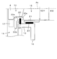
- FIG. 2 schematically shows a region A in FIG.
- the upstream side inner pipe 20 includes a shroud portion 20 a that is disposed in the wheel storage chamber 13 and extends along the edge of the turbine blade 5.
- the upstream side inner pipe 20 includes a ring portion 20 b that is a wall surface of the nozzle portion 14 and a cylindrical portion 20 c that is a part of the wall surface of the discharge passage 15.
- the upstream inner pipe 20 is fixed to the nozzle plate 9 with a plurality of spacer bolts (not shown). At this time, the upstream inner pipe 20 is fixed so that the clearance between the shroud portion 20a and the turbine blade 5 is several hundred ⁇ m.
- a seal member 22 is provided between the upstream inner pipe 20 and the main body 10 to prevent gas from flowing therethrough.
- the downstream inner pipe 21 is provided in the discharge passage 15 so as to be located downstream of the upstream inner pipe 20.
- the downstream inner pipe 21 is fixed to the main body 10 by a support member 23.
- the support member 23 is provided over the entire circumference between the downstream inner tube 21 and the main body 10. As shown in this figure, the support member 23 is disposed in the vicinity of the discharge port 15a.
- the length of the downstream inner tube 21 is set so that the downstream end 21 a protrudes from the main body 10.
- the wall thickness t2 of the downstream inner pipe 21 is thinner than the wall thickness t1 of the upstream inner pipe 20.
- the downstream inner pipe 21 is made of a material having higher corrosion resistance than the material of the upstream inner pipe 20.
- the downstream inner tube 21 may be made of ferritic stainless steel
- the upstream inner tube 20 may be made of austenitic stainless steel or aluminized steel.
- the turbine housing 3 has a nozzle part 14, a wheel accommodating chamber 13, and a discharge passage 15 in a double pipe structure.
- the wall thickness t2 of the downstream inner pipe 21 provided downstream of the turbine wheel 4 is made thinner than the wall thickness t1 of the upstream inner pipe 20, so that the heat capacity of the inner pipe 21 is reduced. it can.
- the downstream side inner pipe 21 is fixed to the main body 10 via the support member 23, the movement of heat from the downstream side inner pipe 21 to the main body 10 can be suppressed.
- the temperature of the downstream inner pipe 21 can be quickly raised by the heat of the exhaust gas or the like, so that the condensed water that has adhered can be quickly evaporated. Therefore, condensed water can be removed quickly. Therefore, corrosion of the downstream side inner pipe 21 can be suppressed.
- downstream inner pipe 21 is made of a material having higher corrosion resistance than the upstream inner pipe 20, it is possible to further suppress the corrosion of the downstream inner pipe 21.
- the wall thickness t1 of the upstream inner pipe 20 is thick, the rigidity of the inner pipe 20 can be increased. Thereby, since the deformation
- the condensed water CW tends to accumulate at the connection portion between the flange 16 and the exhaust pipe 30. Further, as is well known, the flange 16 has a large heat capacity, so the temperature of the exhaust gas tends to decrease.
- the downstream inner pipe 21 is also provided inside the connecting portion. In this case, since the condensed water CW can be quickly evaporated by the heat of the downstream side inner pipe 21, it is possible to suppress the accumulation of condensed water in such a portion, and therefore, corrosion can be suppressed.
- the outer surface 21b of the downstream side inner pipe 21 may be subjected to a surface treatment that has higher heat dissipation than the inner surface 21c.
- the outer surface 21b may be coated with a black body BB.
- the temperature of the portion of the discharge passage 15 of the main body 10 can be raised by the radiant heat from the downstream inner pipe 21. Therefore, generation of condensed water can be prevented.
- the surface processing is not limited to the black body coating, and various methods capable of enhancing the heat dissipation may be applied.
- the outer surface 21b may be rough so that the outer surface 21b is more uneven than the inner surface 21c.
- FIGS. 1 to 4 the same parts as those in FIGS. 1 to 4 are denoted by the same reference numerals, and description thereof is omitted.
- FIG. 5 shows a main part of the turbine housing 3 according to the first modification.
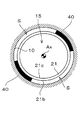
- this figure is the figure which looked at the discharge passage 15 from the direction of the axis line Ax.
- the downstream inner tube 21 is fixed to the main body 10 with a plurality of support members 40 as fixing members.
- the support members 40 are arranged side by side in the circumferential direction. Thereby, a space S connecting the upstream side and the downstream side is formed between the support members 40.
- FIG. 6 shows a main part of the turbine housing 3 according to the second modification.
- the inner diameter ID2 of the downstream inner tube 21 is larger than the outer diameter OD1 of the cylindrical portion 20c of the upstream inner tube 20.
- the downstream inner tube 21 may be disposed so that the upstream end 21d of the downstream inner tube 21 is located outside the cylindrical portion 20c as shown in FIG.
- FIG. 8 shows a main part of the turbine housing 3 according to the third modification.
- the exhaust pipe 30 is attached to the flange 16.
- a flange 31 is provided at the end of the exhaust pipe 30.
- a plurality of stud bolts 32 for fixing the flange 31 is attached to the flange 16.
- Each stud bolt 32 is inserted into the bolt hole 31 a of the flange 31.
- a gap C1 is generated between them.
- the outer diameter OD2 of the downstream inner pipe 21 is made smaller than the inner diameter ID3 of the exhaust pipe 30.
- the outer diameter OD2 of the downstream inner pipe 21 is set so that the gap C2 generated between the downstream inner pipe 21 and the exhaust pipe 30 is larger than the gap C1 described above. In this case, when the exhaust pipe 30 is attached to the turbine housing 3, it is possible to prevent external force from being applied to the downstream side inner pipe 21.
- the present invention can be implemented in various forms without being limited to the above-described forms.
- the upstream inner pipe and the downstream inner pipe may be made of the same material.
- the present invention may be applied to a turbine housing having a double structure in which a main body includes an inner shell and an outer shell provided outside the inner shell.
- the turbine to which the turbine housing of the present invention is applied is not limited to a turbine in which a movable vane is provided in the nozzle portion.
- the ring portion 20b of the upstream side inner pipe 20 is omitted.
- FIG. 9 the same reference numerals are given to portions common to FIG. 2, and description thereof is omitted.
- the condensed water can be quickly evaporated by making the thickness t2 of the downstream inner pipe 21 thinner than the thickness t1 of the upstream inner pipe 20. Therefore, condensed water can be removed quickly.
Landscapes
- Engineering & Computer Science (AREA)
- Mechanical Engineering (AREA)
- General Engineering & Computer Science (AREA)
- Chemical & Material Sciences (AREA)
- Chemical Kinetics & Catalysis (AREA)
- General Chemical & Material Sciences (AREA)
- Combustion & Propulsion (AREA)
- Supercharger (AREA)
Abstract
Description
Claims (6)
- ターボチャージャに組み込まれるタービンに適用され、
タービンホイールを収容するホイール収容室と、一端が前記ホイール収容室の出口に通じ、かつ他端に排出口が設けられた排出通路と、が内部に設けられた本体を備え、前記ホイール収容室を通過したガスは前記排出通路を介して前記排出口から外に排出されるタービンハウジングにおいて、
前記本体の内部には、前記ホイール収容室に配置されて前記タービンホイールのブレードの縁に沿って延びるシュラウド部を有する上流側内管と、前記上流側内管に対してガスの流れ方向の下流側に位置するように前記排出通路に配置された下流側内管と、が設けられ、
前記下流側内管の肉厚が、前記上流側内管の肉厚より薄いタービンハウジング。 - 前記本体の前記排出口の周囲には、前記排気通路の下流に排気管を接続するためのフランジが設けられ、
前記下流側内管の長さは、前記下流側内管のガスの流れ方向の下流側の端部が前記本体から突出するように設定されている請求項1に記載のタービンハウジング。 - 前記下流側内管は、前記下流側内管と前記本体との間に設けられた複数の固定部材にて前記本体に固定され、
前記複数の固定部材は、前記下流側内管の外周に周方向に互いに離して配置されている請求項1又は2に記載のタービンハウジング。 - 前記下流側内管は、前記上流側内管よりも耐腐食性の高い材料で構成されている請求項1~3のいずれか一項に記載のタービンハウジング。
- 前記下流側内管の外面には、前記下流側内管の内面よりも放熱性が高くなる表面加工が施されている請求項1~4のいずれか一項に記載のタービンハウジング。
- 前記上流側内管のガスの流れ方向下流側の端部及び前記下流側内管のガスの流れ方向上流側の端部は、いずれも円筒状をしており、
前記下流側内管のガスの流れ方向上流側の端部の内径は、前記上流側内管のガスの流れ方向下流側の端部の外径よりも大きい請求項1~5のいずれか一項に記載のタービンハウジング。
Priority Applications (5)
| Application Number | Priority Date | Filing Date | Title |
|---|---|---|---|
| CN201180069239.9A CN103429869B (zh) | 2011-04-26 | 2011-04-26 | 涡轮增压器的涡轮壳体 |
| EP11864484.8A EP2703620B1 (en) | 2011-04-26 | 2011-04-26 | Turbine housing for turbocharger |
| JP2013511821A JP5610067B2 (ja) | 2011-04-26 | 2011-04-26 | ターボチャージャのタービンハウジング |
| PCT/JP2011/060159 WO2012147161A1 (ja) | 2011-04-26 | 2011-04-26 | ターボチャージャのタービンハウジング |
| US14/004,487 US8961122B2 (en) | 2011-04-26 | 2011-04-26 | Turbine housing for turbocharger |
Applications Claiming Priority (1)
| Application Number | Priority Date | Filing Date | Title |
|---|---|---|---|
| PCT/JP2011/060159 WO2012147161A1 (ja) | 2011-04-26 | 2011-04-26 | ターボチャージャのタービンハウジング |
Publications (1)
| Publication Number | Publication Date |
|---|---|
| WO2012147161A1 true WO2012147161A1 (ja) | 2012-11-01 |
Family
ID=47071703
Family Applications (1)
| Application Number | Title | Priority Date | Filing Date |
|---|---|---|---|
| PCT/JP2011/060159 Ceased WO2012147161A1 (ja) | 2011-04-26 | 2011-04-26 | ターボチャージャのタービンハウジング |
Country Status (5)
| Country | Link |
|---|---|
| US (1) | US8961122B2 (ja) |
| EP (1) | EP2703620B1 (ja) |
| JP (1) | JP5610067B2 (ja) |
| CN (1) | CN103429869B (ja) |
| WO (1) | WO2012147161A1 (ja) |
Cited By (6)
| Publication number | Priority date | Publication date | Assignee | Title |
|---|---|---|---|---|
| US20120072061A1 (en) * | 2010-09-17 | 2012-03-22 | Hyundai Motor Company | Control system and method for hybrid vehicle |
| JP3186767U (ja) * | 2012-09-04 | 2013-10-24 | ▲炭▼新科技發展有限公司 | ターボチャージャー用ケーシング |
| JP2014126024A (ja) * | 2012-12-27 | 2014-07-07 | Toyota Motor Corp | 内燃機関の過給システム |
| US9850777B2 (en) * | 2013-01-29 | 2017-12-26 | Kabushiki Kaisha Toyota Jidoshokki | Turbochargers |
| CN109113855A (zh) * | 2017-06-23 | 2019-01-01 | 福特全球技术公司 | 用于压缩机入口中的冷凝液捕集的方法和系统 |
| US20240352873A1 (en) * | 2021-09-13 | 2024-10-24 | Turbo Systems Switzerland Ltd. | Oil-cooled exhaust turbine apparatus |
Families Citing this family (8)
| Publication number | Priority date | Publication date | Assignee | Title |
|---|---|---|---|---|
| CN107407198B (zh) * | 2015-03-05 | 2020-07-28 | 三菱重工发动机和增压器株式会社 | 涡轮增压器 |
| US10517421B2 (en) * | 2016-02-15 | 2019-12-31 | Leann Habram | Coffee and tea brewing system and method |
| WO2017168523A1 (ja) * | 2016-03-28 | 2017-10-05 | 三菱重工業株式会社 | 可変容量型ターボチャージャ |
| DE102017103980A1 (de) * | 2017-02-27 | 2018-08-30 | Man Diesel & Turbo Se | Turbolader |
| DE112018004729B4 (de) | 2017-08-28 | 2024-10-02 | Kabushiki Kaisha Toyota Jidoshokki | Turbolader |
| CN111033012B (zh) * | 2017-08-28 | 2021-12-28 | 株式会社丰田自动织机 | 涡轮增压器 |
| JP6930652B2 (ja) | 2018-02-19 | 2021-09-01 | 株式会社Ihi | タービン |
| DE112020004888T5 (de) * | 2019-10-09 | 2022-06-30 | Ihi Corporation | Ablaufaufbau und Turbolader |
Citations (11)
| Publication number | Priority date | Publication date | Assignee | Title |
|---|---|---|---|---|
| JPS5910709A (ja) * | 1982-07-08 | 1984-01-20 | Nissan Motor Co Ltd | タ−ビンシユラウド |
| JPS6024839U (ja) * | 1983-07-27 | 1985-02-20 | いすゞ自動車株式会社 | タ−ボチヤ−ジヤの断熱構造 |
| JP2002004871A (ja) | 2000-04-19 | 2002-01-09 | Aisin Takaoka Ltd | 過給機のタービンハウジング |
| JP2002519581A (ja) | 1998-07-02 | 2002-07-02 | アライド−シグナル・インコーポレーテッド | 低速度高圧縮比ターボチャージャ |
| JP2005163692A (ja) * | 2003-12-04 | 2005-06-23 | Toyota Motor Corp | 作動流体逃がし通路を有する排気タービン |
| JP2007120396A (ja) * | 2005-10-27 | 2007-05-17 | Toyota Motor Corp | 内燃機関用ターボ過給機のタービンハウジング |
| JP2007278221A (ja) | 2006-04-10 | 2007-10-25 | Toyota Motor Corp | 内燃機関のシール構造及びそのシール構造に使用されるガスケット |
| JP2008121470A (ja) * | 2006-11-09 | 2008-05-29 | Toyota Motor Corp | ターボチャージャ |
| JP2008208787A (ja) * | 2007-02-27 | 2008-09-11 | Toyota Motor Corp | 内燃機関のターボチャージャ |
| JP2009041551A (ja) | 2007-08-13 | 2009-02-26 | Toyota Motor Corp | 内燃機関の排気還流装置 |
| JP2010112195A (ja) | 2008-11-04 | 2010-05-20 | Ihi Corp | ターボチャージャのシール装置 |
Family Cites Families (5)
| Publication number | Priority date | Publication date | Assignee | Title |
|---|---|---|---|---|
| JP3561483B2 (ja) | 2001-05-25 | 2004-09-02 | アイシン高丘株式会社 | 過給機のタービンハウジング |
| JP2006161579A (ja) | 2004-12-02 | 2006-06-22 | Toyota Motor Corp | ターボチャージャのタービンハウジング |
| EP1948909A1 (en) * | 2005-11-16 | 2008-07-30 | Honeywell International Inc. | Turbocharger having piston-type variable nozzle with integrated actuation system |
| JP2007309139A (ja) | 2006-05-16 | 2007-11-29 | Toyota Motor Corp | ターボチャージャ |
| JP5045304B2 (ja) * | 2007-08-16 | 2012-10-10 | 株式会社Ihi | ターボチャージャ |
-
2011
- 2011-04-26 WO PCT/JP2011/060159 patent/WO2012147161A1/ja not_active Ceased
- 2011-04-26 US US14/004,487 patent/US8961122B2/en active Active
- 2011-04-26 EP EP11864484.8A patent/EP2703620B1/en not_active Not-in-force
- 2011-04-26 JP JP2013511821A patent/JP5610067B2/ja not_active Expired - Fee Related
- 2011-04-26 CN CN201180069239.9A patent/CN103429869B/zh not_active Expired - Fee Related
Patent Citations (11)
| Publication number | Priority date | Publication date | Assignee | Title |
|---|---|---|---|---|
| JPS5910709A (ja) * | 1982-07-08 | 1984-01-20 | Nissan Motor Co Ltd | タ−ビンシユラウド |
| JPS6024839U (ja) * | 1983-07-27 | 1985-02-20 | いすゞ自動車株式会社 | タ−ボチヤ−ジヤの断熱構造 |
| JP2002519581A (ja) | 1998-07-02 | 2002-07-02 | アライド−シグナル・インコーポレーテッド | 低速度高圧縮比ターボチャージャ |
| JP2002004871A (ja) | 2000-04-19 | 2002-01-09 | Aisin Takaoka Ltd | 過給機のタービンハウジング |
| JP2005163692A (ja) * | 2003-12-04 | 2005-06-23 | Toyota Motor Corp | 作動流体逃がし通路を有する排気タービン |
| JP2007120396A (ja) * | 2005-10-27 | 2007-05-17 | Toyota Motor Corp | 内燃機関用ターボ過給機のタービンハウジング |
| JP2007278221A (ja) | 2006-04-10 | 2007-10-25 | Toyota Motor Corp | 内燃機関のシール構造及びそのシール構造に使用されるガスケット |
| JP2008121470A (ja) * | 2006-11-09 | 2008-05-29 | Toyota Motor Corp | ターボチャージャ |
| JP2008208787A (ja) * | 2007-02-27 | 2008-09-11 | Toyota Motor Corp | 内燃機関のターボチャージャ |
| JP2009041551A (ja) | 2007-08-13 | 2009-02-26 | Toyota Motor Corp | 内燃機関の排気還流装置 |
| JP2010112195A (ja) | 2008-11-04 | 2010-05-20 | Ihi Corp | ターボチャージャのシール装置 |
Non-Patent Citations (1)
| Title |
|---|
| See also references of EP2703620A4 * |
Cited By (7)
| Publication number | Priority date | Publication date | Assignee | Title |
|---|---|---|---|---|
| US20120072061A1 (en) * | 2010-09-17 | 2012-03-22 | Hyundai Motor Company | Control system and method for hybrid vehicle |
| JP3186767U (ja) * | 2012-09-04 | 2013-10-24 | ▲炭▼新科技發展有限公司 | ターボチャージャー用ケーシング |
| JP2014126024A (ja) * | 2012-12-27 | 2014-07-07 | Toyota Motor Corp | 内燃機関の過給システム |
| US9850777B2 (en) * | 2013-01-29 | 2017-12-26 | Kabushiki Kaisha Toyota Jidoshokki | Turbochargers |
| CN109113855A (zh) * | 2017-06-23 | 2019-01-01 | 福特全球技术公司 | 用于压缩机入口中的冷凝液捕集的方法和系统 |
| US20240352873A1 (en) * | 2021-09-13 | 2024-10-24 | Turbo Systems Switzerland Ltd. | Oil-cooled exhaust turbine apparatus |
| US12372009B2 (en) * | 2021-09-13 | 2025-07-29 | Accelleron Switzerland Ltd. | Oil-cooled exhaust turbine apparatus |
Also Published As
| Publication number | Publication date |
|---|---|
| CN103429869B (zh) | 2015-06-10 |
| EP2703620A1 (en) | 2014-03-05 |
| EP2703620A4 (en) | 2014-07-30 |
| JPWO2012147161A1 (ja) | 2014-07-28 |
| US20140037436A1 (en) | 2014-02-06 |
| EP2703620B1 (en) | 2015-07-01 |
| JP5610067B2 (ja) | 2014-10-22 |
| CN103429869A (zh) | 2013-12-04 |
| US8961122B2 (en) | 2015-02-24 |
Similar Documents
| Publication | Publication Date | Title |
|---|---|---|
| JP5610067B2 (ja) | ターボチャージャのタービンハウジング | |
| JP6351049B2 (ja) | タービンハウジングおよびタービンハウジングの製造方法 | |
| EP3260670B1 (en) | Turbine housing | |
| EP2617961B1 (en) | Radial turbine | |
| US8251650B2 (en) | Compressor housing | |
| EP2623728B1 (en) | Variable geometry turbine | |
| US9810225B2 (en) | Turbine for turbocharger and method for assembling turbocharger | |
| WO2015099199A1 (ja) | タービン | |
| JP5866836B2 (ja) | 遠心圧縮機 | |
| EP3078834B1 (en) | Metallic plate turbine housing | |
| JP5281724B1 (ja) | 過給機用軸流タービン | |
| JP6500448B2 (ja) | 過給機 | |
| JP6834862B2 (ja) | ターボチャージャ | |
| JP5772207B2 (ja) | ラジアルタービン及び過給機 | |
| US10378432B2 (en) | Radial turbine casing | |
| JP7774670B2 (ja) | インペラ、及び遠心圧縮機 | |
| JP6670862B2 (ja) | 遠心圧縮機、および、過給機 | |
| JP6267063B2 (ja) | 可変ノズルターボチャージャー | |
| JP6745331B2 (ja) | 回転機械、ターボチャージャ | |
| JP6064310B2 (ja) | タービン及び車両用過給機 | |
| US20220145772A1 (en) | Nozzle vane |
Legal Events
| Date | Code | Title | Description |
|---|---|---|---|
| 121 | Ep: the epo has been informed by wipo that ep was designated in this application |
Ref document number: 11864484 Country of ref document: EP Kind code of ref document: A1 |
|
| ENP | Entry into the national phase |
Ref document number: 2013511821 Country of ref document: JP Kind code of ref document: A |
|
| WWE | Wipo information: entry into national phase |
Ref document number: 2011864484 Country of ref document: EP |
|
| WWE | Wipo information: entry into national phase |
Ref document number: 14004487 Country of ref document: US |
|
| NENP | Non-entry into the national phase |
Ref country code: DE |