WO2012147311A1 - 暖房システム及び暖房システム制御方法 - Google Patents
暖房システム及び暖房システム制御方法 Download PDFInfo
- Publication number
- WO2012147311A1 WO2012147311A1 PCT/JP2012/002700 JP2012002700W WO2012147311A1 WO 2012147311 A1 WO2012147311 A1 WO 2012147311A1 JP 2012002700 W JP2012002700 W JP 2012002700W WO 2012147311 A1 WO2012147311 A1 WO 2012147311A1
- Authority
- WO
- WIPO (PCT)
- Prior art keywords
- shut
- heat
- time zone
- heating system
- power consumption
- Prior art date
- Legal status (The legal status is an assumption and is not a legal conclusion. Google has not performed a legal analysis and makes no representation as to the accuracy of the status listed.)
- Ceased
Links
Images


Classifications
-
- F—MECHANICAL ENGINEERING; LIGHTING; HEATING; WEAPONS; BLASTING
- F24—HEATING; RANGES; VENTILATING
- F24D—DOMESTIC- OR SPACE-HEATING SYSTEMS, e.g. CENTRAL HEATING SYSTEMS; DOMESTIC HOT-WATER SUPPLY SYSTEMS; ELEMENTS OR COMPONENTS THEREFOR
- F24D19/00—Details
- F24D19/10—Arrangement or mounting of control or safety devices
- F24D19/1006—Arrangement or mounting of control or safety devices for water heating systems
- F24D19/1009—Arrangement or mounting of control or safety devices for water heating systems for central heating
- F24D19/1048—Counting of energy consumption
-
- F—MECHANICAL ENGINEERING; LIGHTING; HEATING; WEAPONS; BLASTING
- F24—HEATING; RANGES; VENTILATING
- F24D—DOMESTIC- OR SPACE-HEATING SYSTEMS, e.g. CENTRAL HEATING SYSTEMS; DOMESTIC HOT-WATER SUPPLY SYSTEMS; ELEMENTS OR COMPONENTS THEREFOR
- F24D19/00—Details
- F24D19/10—Arrangement or mounting of control or safety devices
- F24D19/1006—Arrangement or mounting of control or safety devices for water heating systems
- F24D19/1009—Arrangement or mounting of control or safety devices for water heating systems for central heating
- F24D19/1039—Arrangement or mounting of control or safety devices for water heating systems for central heating the system uses a heat pump
-
- F—MECHANICAL ENGINEERING; LIGHTING; HEATING; WEAPONS; BLASTING
- F24—HEATING; RANGES; VENTILATING
- F24H—FLUID HEATERS, e.g. WATER OR AIR HEATERS, HAVING HEAT-GENERATING MEANS, e.g. HEAT PUMPS, IN GENERAL
- F24H15/00—Control of fluid heaters
- F24H15/10—Control of fluid heaters characterised by the purpose of the control
- F24H15/144—Measuring or calculating energy consumption
-
- F—MECHANICAL ENGINEERING; LIGHTING; HEATING; WEAPONS; BLASTING
- F24—HEATING; RANGES; VENTILATING
- F24H—FLUID HEATERS, e.g. WATER OR AIR HEATERS, HAVING HEAT-GENERATING MEANS, e.g. HEAT PUMPS, IN GENERAL
- F24H15/00—Control of fluid heaters
- F24H15/10—Control of fluid heaters characterised by the purpose of the control
- F24H15/168—Reducing the electric power demand peak
-
- F—MECHANICAL ENGINEERING; LIGHTING; HEATING; WEAPONS; BLASTING
- F24—HEATING; RANGES; VENTILATING
- F24H—FLUID HEATERS, e.g. WATER OR AIR HEATERS, HAVING HEAT-GENERATING MEANS, e.g. HEAT PUMPS, IN GENERAL
- F24H15/00—Control of fluid heaters
- F24H15/10—Control of fluid heaters characterised by the purpose of the control
- F24H15/176—Improving or maintaining comfort of users
-
- F—MECHANICAL ENGINEERING; LIGHTING; HEATING; WEAPONS; BLASTING
- F24—HEATING; RANGES; VENTILATING
- F24H—FLUID HEATERS, e.g. WATER OR AIR HEATERS, HAVING HEAT-GENERATING MEANS, e.g. HEAT PUMPS, IN GENERAL
- F24H15/00—Control of fluid heaters
- F24H15/20—Control of fluid heaters characterised by control inputs
- F24H15/281—Input from user
-
- F—MECHANICAL ENGINEERING; LIGHTING; HEATING; WEAPONS; BLASTING
- F24—HEATING; RANGES; VENTILATING
- F24H—FLUID HEATERS, e.g. WATER OR AIR HEATERS, HAVING HEAT-GENERATING MEANS, e.g. HEAT PUMPS, IN GENERAL
- F24H15/00—Control of fluid heaters
- F24H15/20—Control of fluid heaters characterised by control inputs
- F24H15/296—Information from neighbouring devices
-
- F—MECHANICAL ENGINEERING; LIGHTING; HEATING; WEAPONS; BLASTING
- F24—HEATING; RANGES; VENTILATING
- F24H—FLUID HEATERS, e.g. WATER OR AIR HEATERS, HAVING HEAT-GENERATING MEANS, e.g. HEAT PUMPS, IN GENERAL
- F24H15/00—Control of fluid heaters
- F24H15/30—Control of fluid heaters characterised by control outputs; characterised by the components to be controlled
- F24H15/375—Control of heat pumps
-
- F—MECHANICAL ENGINEERING; LIGHTING; HEATING; WEAPONS; BLASTING
- F24—HEATING; RANGES; VENTILATING
- F24H—FLUID HEATERS, e.g. WATER OR AIR HEATERS, HAVING HEAT-GENERATING MEANS, e.g. HEAT PUMPS, IN GENERAL
- F24H15/00—Control of fluid heaters
- F24H15/40—Control of fluid heaters characterised by the type of controllers
- F24H15/414—Control of fluid heaters characterised by the type of controllers using electronic processing, e.g. computer-based
-
- G—PHYSICS
- G05—CONTROLLING; REGULATING
- G05D—SYSTEMS FOR CONTROLLING OR REGULATING NON-ELECTRIC VARIABLES
- G05D23/00—Control of temperature
- G05D23/19—Control of temperature characterised by the use of electric means
- G05D23/1919—Control of temperature characterised by the use of electric means characterised by the type of controller
- G05D23/1923—Control of temperature characterised by the use of electric means characterised by the type of controller using thermal energy, the cost of which varies in function of time
-
- H—ELECTRICITY
- H02—GENERATION; CONVERSION OR DISTRIBUTION OF ELECTRIC POWER
- H02J—ELECTRIC POWER NETWORKS; CIRCUIT ARRANGEMENTS OR SYSTEMS FOR SUPPLYING OR DISTRIBUTING ELECTRIC POWER; SYSTEMS FOR STORING ELECTRIC ENERGY
- H02J3/00—Circuit arrangements for AC mains or AC distribution networks
- H02J3/12—Arrangements for adjusting voltage in AC networks by changing a characteristic of the network load
- H02J3/14—Arrangements for adjusting voltage in AC networks by changing a characteristic of the network load by switching loads on to, or off from, the networks, e.g. progressively balanced loading
-
- F—MECHANICAL ENGINEERING; LIGHTING; HEATING; WEAPONS; BLASTING
- F24—HEATING; RANGES; VENTILATING
- F24D—DOMESTIC- OR SPACE-HEATING SYSTEMS, e.g. CENTRAL HEATING SYSTEMS; DOMESTIC HOT-WATER SUPPLY SYSTEMS; ELEMENTS OR COMPONENTS THEREFOR
- F24D2200/00—Heat sources or energy sources
- F24D2200/12—Heat pump
- F24D2200/123—Compression type heat pumps
-
- F—MECHANICAL ENGINEERING; LIGHTING; HEATING; WEAPONS; BLASTING
- F24—HEATING; RANGES; VENTILATING
- F24D—DOMESTIC- OR SPACE-HEATING SYSTEMS, e.g. CENTRAL HEATING SYSTEMS; DOMESTIC HOT-WATER SUPPLY SYSTEMS; ELEMENTS OR COMPONENTS THEREFOR
- F24D3/00—Hot-water central heating systems
- F24D3/18—Hot-water central heating systems using heat pumps
-
- F—MECHANICAL ENGINEERING; LIGHTING; HEATING; WEAPONS; BLASTING
- F24—HEATING; RANGES; VENTILATING
- F24H—FLUID HEATERS, e.g. WATER OR AIR HEATERS, HAVING HEAT-GENERATING MEANS, e.g. HEAT PUMPS, IN GENERAL
- F24H15/00—Control of fluid heaters
- F24H15/40—Control of fluid heaters characterised by the type of controllers
- F24H15/414—Control of fluid heaters characterised by the type of controllers using electronic processing, e.g. computer-based
- F24H15/45—Control of fluid heaters characterised by the type of controllers using electronic processing, e.g. computer-based remotely accessible
-
- H—ELECTRICITY
- H02—GENERATION; CONVERSION OR DISTRIBUTION OF ELECTRIC POWER
- H02J—ELECTRIC POWER NETWORKS; CIRCUIT ARRANGEMENTS OR SYSTEMS FOR SUPPLYING OR DISTRIBUTING ELECTRIC POWER; SYSTEMS FOR STORING ELECTRIC ENERGY
- H02J2105/00—Networks for supplying or distributing electric power characterised by their spatial reach or by the load
- H02J2105/40—Networks for supplying or distributing electric power characterised by their spatial reach or by the load characterised by the loads connecting to the networks or being supplied by the networks
- H02J2105/42—Home appliances
-
- H—ELECTRICITY
- H02—GENERATION; CONVERSION OR DISTRIBUTION OF ELECTRIC POWER
- H02J—ELECTRIC POWER NETWORKS; CIRCUIT ARRANGEMENTS OR SYSTEMS FOR SUPPLYING OR DISTRIBUTING ELECTRIC POWER; SYSTEMS FOR STORING ELECTRIC ENERGY
- H02J2105/00—Networks for supplying or distributing electric power characterised by their spatial reach or by the load
- H02J2105/50—Networks for supplying or distributing electric power characterised by their spatial reach or by the load for selectively controlling the operation of the loads
- H02J2105/54—Networks for supplying or distributing electric power characterised by their spatial reach or by the load for selectively controlling the operation of the loads according to a non-electrical condition, e.g. temperature
- H02J2105/55—Networks for supplying or distributing electric power characterised by their spatial reach or by the load for selectively controlling the operation of the loads according to a non-electrical condition, e.g. temperature according to an economic condition, e.g. tariff-based load management
-
- Y—GENERAL TAGGING OF NEW TECHNOLOGICAL DEVELOPMENTS; GENERAL TAGGING OF CROSS-SECTIONAL TECHNOLOGIES SPANNING OVER SEVERAL SECTIONS OF THE IPC; TECHNICAL SUBJECTS COVERED BY FORMER USPC CROSS-REFERENCE ART COLLECTIONS [XRACs] AND DIGESTS
- Y02—TECHNOLOGIES OR APPLICATIONS FOR MITIGATION OR ADAPTATION AGAINST CLIMATE CHANGE
- Y02B—CLIMATE CHANGE MITIGATION TECHNOLOGIES RELATED TO BUILDINGS, e.g. HOUSING, HOUSE APPLIANCES OR RELATED END-USER APPLICATIONS
- Y02B30/00—Energy efficient heating, ventilation or air conditioning [HVAC]
- Y02B30/12—Hot water central heating systems using heat pumps
-
- Y—GENERAL TAGGING OF NEW TECHNOLOGICAL DEVELOPMENTS; GENERAL TAGGING OF CROSS-SECTIONAL TECHNOLOGIES SPANNING OVER SEVERAL SECTIONS OF THE IPC; TECHNICAL SUBJECTS COVERED BY FORMER USPC CROSS-REFERENCE ART COLLECTIONS [XRACs] AND DIGESTS
- Y02—TECHNOLOGIES OR APPLICATIONS FOR MITIGATION OR ADAPTATION AGAINST CLIMATE CHANGE
- Y02B—CLIMATE CHANGE MITIGATION TECHNOLOGIES RELATED TO BUILDINGS, e.g. HOUSING, HOUSE APPLIANCES OR RELATED END-USER APPLICATIONS
- Y02B30/00—Energy efficient heating, ventilation or air conditioning [HVAC]
- Y02B30/70—Efficient control or regulation technologies, e.g. for control of refrigerant flow, motor or heating
-
- Y—GENERAL TAGGING OF NEW TECHNOLOGICAL DEVELOPMENTS; GENERAL TAGGING OF CROSS-SECTIONAL TECHNOLOGIES SPANNING OVER SEVERAL SECTIONS OF THE IPC; TECHNICAL SUBJECTS COVERED BY FORMER USPC CROSS-REFERENCE ART COLLECTIONS [XRACs] AND DIGESTS
- Y02—TECHNOLOGIES OR APPLICATIONS FOR MITIGATION OR ADAPTATION AGAINST CLIMATE CHANGE
- Y02B—CLIMATE CHANGE MITIGATION TECHNOLOGIES RELATED TO BUILDINGS, e.g. HOUSING, HOUSE APPLIANCES OR RELATED END-USER APPLICATIONS
- Y02B70/00—Technologies for an efficient end-user side electric power management and consumption
- Y02B70/30—Systems integrating technologies related to power network operation and communication or information technologies for improving the carbon footprint of the management of residential or tertiary loads, i.e. smart grids as climate change mitigation technology in the buildings sector, including also the last stages of power distribution and the control, monitoring or operating management systems at local level
- Y02B70/3225—Demand response systems, e.g. load shedding, peak shaving
-
- Y—GENERAL TAGGING OF NEW TECHNOLOGICAL DEVELOPMENTS; GENERAL TAGGING OF CROSS-SECTIONAL TECHNOLOGIES SPANNING OVER SEVERAL SECTIONS OF THE IPC; TECHNICAL SUBJECTS COVERED BY FORMER USPC CROSS-REFERENCE ART COLLECTIONS [XRACs] AND DIGESTS
- Y04—INFORMATION OR COMMUNICATION TECHNOLOGIES HAVING AN IMPACT ON OTHER TECHNOLOGY AREAS
- Y04S—SYSTEMS INTEGRATING TECHNOLOGIES RELATED TO POWER NETWORK OPERATION, COMMUNICATION OR INFORMATION TECHNOLOGIES FOR IMPROVING THE ELECTRICAL POWER GENERATION, TRANSMISSION, DISTRIBUTION, MANAGEMENT OR USAGE, i.e. SMART GRIDS
- Y04S20/00—Management or operation of end-user stationary applications or the last stages of power distribution; Controlling, monitoring or operating thereof
- Y04S20/20—End-user application control systems
- Y04S20/222—Demand response systems, e.g. load shedding, peak shaving
-
- Y—GENERAL TAGGING OF NEW TECHNOLOGICAL DEVELOPMENTS; GENERAL TAGGING OF CROSS-SECTIONAL TECHNOLOGIES SPANNING OVER SEVERAL SECTIONS OF THE IPC; TECHNICAL SUBJECTS COVERED BY FORMER USPC CROSS-REFERENCE ART COLLECTIONS [XRACs] AND DIGESTS
- Y04—INFORMATION OR COMMUNICATION TECHNOLOGIES HAVING AN IMPACT ON OTHER TECHNOLOGY AREAS
- Y04S—SYSTEMS INTEGRATING TECHNOLOGIES RELATED TO POWER NETWORK OPERATION, COMMUNICATION OR INFORMATION TECHNOLOGIES FOR IMPROVING THE ELECTRICAL POWER GENERATION, TRANSMISSION, DISTRIBUTION, MANAGEMENT OR USAGE, i.e. SMART GRIDS
- Y04S20/00—Management or operation of end-user stationary applications or the last stages of power distribution; Controlling, monitoring or operating thereof
- Y04S20/20—End-user application control systems
- Y04S20/242—Home appliances
- Y04S20/244—Home appliances the home appliances being or involving heating ventilating and air conditioning [HVAC] units
-
- Y—GENERAL TAGGING OF NEW TECHNOLOGICAL DEVELOPMENTS; GENERAL TAGGING OF CROSS-SECTIONAL TECHNOLOGIES SPANNING OVER SEVERAL SECTIONS OF THE IPC; TECHNICAL SUBJECTS COVERED BY FORMER USPC CROSS-REFERENCE ART COLLECTIONS [XRACs] AND DIGESTS
- Y04—INFORMATION OR COMMUNICATION TECHNOLOGIES HAVING AN IMPACT ON OTHER TECHNOLOGY AREAS
- Y04S—SYSTEMS INTEGRATING TECHNOLOGIES RELATED TO POWER NETWORK OPERATION, COMMUNICATION OR INFORMATION TECHNOLOGIES FOR IMPROVING THE ELECTRICAL POWER GENERATION, TRANSMISSION, DISTRIBUTION, MANAGEMENT OR USAGE, i.e. SMART GRIDS
- Y04S50/00—Market activities related to the operation of systems integrating technologies related to power network operation or related to communication or information technologies
- Y04S50/10—Energy trading, including energy flowing from end-user application to grid
Definitions
- the present invention relates to a heating system, and more particularly to a heat pump heating system.
- shut-off time zone a predetermined period of a day
- shutoff an inexpensive power charge
- the manufacturer of the heat pump heating system is provided with a relay switch that turns on or off when receiving a ripple signal from the energy supplier in order to cope with the control from the outside.
- the present invention has been made in view of the above circumstances, and a heat pump heating system capable of appropriately storing heat necessary for a period in which power supply is temporarily stopped by a shut-off signal, and An object is to provide a control method thereof.
- the heating system receives power supply from a power supply source and maintains the target temperature in a predetermined temperature range including a preset temperature.
- a heat pump unit that generates heat using electric power supplied from the power supply source
- a heat radiating unit that radiates heat generated by the heat pump unit
- a predetermined heat pump unit In order to stop the heat generation in the shut-off time zone and to maintain the target at the set temperature, the SOP heat amount, which is the heat amount to be radiated from the heat radiating section in the shut-off time zone, is set before and after the shut-off time zone.
- a heating system control unit that accumulates and heats the heat pump unit during the time period.
- the said heating system control part is the time before and behind the said shut-off time slot
- zone may be below an allowable peak electric power. Distribute it to the belt and heat it.
- the SOP heat quantity is distributed and regenerated so that the maximum power consumption in the time zones before and after the shut-off time zone is both equal to or lower than the allowable peak power, not only comfort but also the shut-off is achieved.
- the power peaks in the time zones before and after the off time zone can also be leveled.
- FIG. 1 is a diagram illustrating a heat pump heating system according to the first embodiment.
- FIG. 2 is a detailed configuration diagram of the heat pump heating device and the heating system control unit according to the first embodiment.
- FIG. 3 is a flowchart of a process for creating an operation plan of the heat pump heating device according to the first embodiment.
- FIG. 4A is a table showing an example of a prediction result of power consumption when the prior heat storage target room temperature is 24 ° C.
- FIG. 4B is a table showing a calculation result of the maximum value of the total power consumption for each prior heat storage target room temperature.
- FIG. 5A is a graph showing changes in HP output heat amount and room temperature for each prior heat storage target room temperature.
- FIG. 5B is a graph showing a transition of power consumption for each prior heat storage target room temperature.
- FIG. 6 is a flowchart of a process for creating an operation plan of the heat pump heating device according to the second embodiment.
- FIG. 7 is a table showing the calculation result of the maximum value of the total power consumption for each prior heat storage target room temperature.
- FIG. 8 is a flowchart of processing for creating an operation plan of the heat pump heating device according to the third embodiment.
- FIG. 9A is a graph showing changes in HP output heat amount and room temperature for each prior heat storage target room temperature.
- FIG. 9B is a graph showing a transition of power consumption for each prior heat storage target room temperature.
- FIG. 10 is a table showing the calculation result of the maximum value of the total power consumption for each prior heat storage target room temperature.
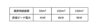
- FIG. 11 is a table showing an example of allowable peak power that varies depending on the floor area.
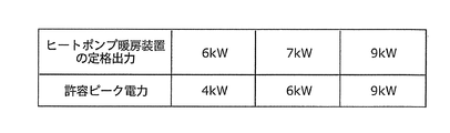
- FIG. 12 is a table showing an example of allowable peak power that varies according to the rated
- the heating system receives power supply from a power supply source and maintains the target temperature in a predetermined temperature range including a preset temperature.
- a heat pump unit that generates heat using electric power supplied from the power supply source
- a heat radiating unit that radiates heat generated by the heat pump unit
- a predetermined heat pump unit In order to stop the heat generation in the shut-off time zone and to maintain the target at the set temperature, the SOP heat amount, which is the heat amount to be radiated from the heat radiating section in the shut-off time zone, is set before and after the shut-off time zone.
- a heating system control unit that accumulates and heats the heat pump unit during the time period.
- the said heating system control part is the time before and behind the said shut-off time slot
- zone may be below an allowable peak electric power. Distribute it to the belt and heat it.
- the amount of SOP heat that should be radiated during the shut-off time zone is distributed to the time zones before and after it to generate heat, thereby suppressing power consumption peaks in the time zones before and after the shut-off time zone. You can get a heating system.
- the heating system control unit is distributed with the transition of the raw heat consumption consumed by the heat pump unit to maintain the target at the set temperature in each of the time zones before and after the shut-off time zone.
- the SOP is set so that the maximum value of the total power consumption, which is the sum of the general power consumption, the raw heat power consumption, and the product power consumption, is less than or equal to the allowable peak power.
- the upper power consumption in the time zone before the shut-off time zone is to increase the target temperature to a pre-heat storage target temperature higher than the set temperature at the start time of the shut-off time zone. It may be power consumption consumed by the heat pump unit. Similarly, the upper power consumption in the time zone after the shut-off time zone is consumed by the heat pump unit in order to raise the target temperature at the end time of the shut-off time zone to the set temperature. It may be power consumption. Furthermore, the said heating system control part may be provided with the detection part which detects object temperature and external temperature. And the said prediction part may predict the transition of the said upper-layer power consumption of each time slot
- the operation planning unit may include the shut-off among a plurality of the pre-heat storage target temperatures at which the maximum value of the total power consumption in each of the time zones before and after the shut-off time zone is less than or equal to the allowable peak power. You may select the said prior heat storage target temperature from which the maximum value of the said total power consumption through the time slot
- the operation planning unit may include the shut-off among a plurality of the pre-heat storage target temperatures at which the maximum value of the total power consumption in each of the time zones before and after the shut-off time zone is less than or equal to the allowable peak power.
- You may select the said prior heat storage target temperature from which the minimum temperature of the object in a time slot
- the prediction unit may predict a shut-off time, which is a time during which the target temperature decreases from the preliminary heat storage target temperature to the threshold temperature, for each of the plurality of preliminary heat storage target temperatures.
- the heating system control unit distributes to the time zone after the shut-off time zone at a timing when the shut-off time corresponding to the pre-heat storage target temperature selected from the start of the shut-off time zone has elapsed.
- heat amount which carried out may be piled up on the said heat pump part, and you may make it heat. Thereby, a user's comfort can be maintained further.
- the operation planning unit may select the pre-heat storage target temperature that can maximize the shut-off time among the plurality of pre-heat storage target temperatures.
- the operation planning unit creates the operation plan at a timing at which a signal including information specifying the shut-off time zone is received from the power supply source a predetermined time before the start of the shut-off time zone. May be executed.
- the signal may include information indicating the allowable peak power.
- the heating system control unit may accept an input of the allowable peak power from a user.
- the allowable peak power may be set based on the heat insulation performance of the building where the heating system is installed.
- the allowable peak power in the time zone before the shutdown time zone may be individually set so as to be larger than the allowable peak power in the time zone after the shutdown time zone.
- the predicted value of the total power consumption in the time zone before the shut-off time zone may have a higher prediction error than the predicted value of the total power consumption in the time zone before the shut-off time zone. Therefore, the power consumption peak can be more reliably suppressed by setting the allowable peak power in the time zone after the shut-off time zone to be relatively small.
- the heating system includes a heating device including the heat pump unit, the heat dissipation unit, and an HP control unit that controls the heat pump unit in accordance with an instruction from the heating system control unit, and the heating device is separate from the heating device.
- the heating system controller configured as described above may be provided.
- the heating device not only the heating device but also other devices can be controlled by the heating system control unit. Further, when used in an environment where control for shutoff is not required, it is sufficient to install only a heating device.
- a method for controlling a heating system is a method for controlling a heating system that receives supply of electric power from a power supply source and maintains a target temperature in a predetermined temperature range including a predetermined set temperature. It is.
- the heating system includes a heat pump unit that generates heat using electric power supplied from the power supply source, and a heat radiating unit that radiates heat generated by the heat pump unit.
- the heat pump unit stops heat generation in a predetermined shut-off time zone, and heat is radiated from the heat radiating unit in the shut-off time zone in order to maintain the target at the set temperature.
- the SOP heat amount is set to a time before and after the shut-off time zone so that the maximum power consumption in each time zone before and after the shut-off time zone is less than or equal to the allowable peak power. Distribute it to the belt and heat it.
- the heating system control step is distributed with the transition of the heat consumption power consumed by the heat pump unit in order to maintain the target at the set temperature in each of the time zones before and after the shut-off time zone.
- An operation plan step for creating an operation plan for distributing heat to generate heat may be included. In the heating system control step, the heat pump may be controlled based on the operation plan created in the operation plan step.
- the upper power consumption in the time zone before the shut-off time zone is to increase the target temperature to a pre-heat storage target temperature higher than the set temperature at the start time of the shut-off time zone. It may be power consumption consumed by the heat pump unit. Similarly, the upper power consumption in the time zone after the shut-off time zone is consumed by the heat pump unit in order to raise the target temperature at the end time of the shut-off time zone to the set temperature. It may be power consumption. Furthermore, the heating system control step may include a detection step of detecting a target temperature and an outside air temperature. In the prediction step, transition of the upper power consumption in each time zone before and after the shut-off time zone may be predicted based on the detection result in the detection step.
- a shut-off time that is a time during which the target temperature decreases from the preliminary heat storage target temperature to the threshold temperature may be predicted for each of the plurality of preliminary heat storage target temperatures.
- distribution is made to a time zone after the shut-off time zone at a timing when the shut-off time corresponding to the pre-heat storage target temperature selected from the start of the shut-off time zone has elapsed.
- heat amount which carried out may be piled up on the said heat pump part, and you may make it heat.
- the pre-heat storage target temperature that can maximize the shut-off time may be selected from the plurality of pre-heat storage target temperatures.
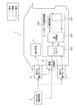
- FIG. 1 is a diagram showing a heat pump heating system 1 according to Embodiment 1 of the present invention.
- power is supplied from an energy supplier (power supply source) 4 to a house (building) through first and second power systems.
- the first power system is a power system to which power is stably supplied.
- the first power system is a power system having a relatively high power rate, and the power consumption is measured by the first power meter 6.
- the second electric power system is an electric power system that can be stopped by the energy supplier 4 at an arbitrary time zone.
- the second power system is a power system whose power rate is lower than that of the first power system, and the power consumption is measured by the second power meter 7.
- the heat pump heating device 100 includes at least a heat pump (raw heat unit) 101, a heat exchanger 102, and a heating device (heat radiating unit) 103.
- the heat pump heating device 100 dissipates the heat generated by the heat pump 101 from the heating device 103 through the heat exchanger 102, whereby the room temperature of the room in which the heating device 103 is installed includes a predetermined set temperature. It is the apparatus which maintains in the temperature range.
- the predetermined temperature range is, for example, a range in which the prior heat storage target room temperature (described later) is the upper limit and the threshold temperature (described later) is the lower limit.
- 1st electric power meter 6 measures the power consumption of apparatuses (namely, electric power load 5) other than the heating system control part 8 and the heat pump type heating apparatus 100.
- the heating system control unit 8 and the power load 5 operate by receiving power supply from the energy supplier 4 through the first power system.
- the 2nd electric power meter 7 measures the electric power consumption of the component of the heat pump type heating apparatus 100, such as a compressor, a pump, a fan (not shown). That is, each component of the heat pump heating device 100 operates by receiving power supply from the energy supplier 4 through the second power system.
- the heating system control unit 8 has a function of communicating with the energy supplier 4 and gives a control command to the heat pump heating device 100. For example, the heating system control unit 8 causes the heat pump heating device 100 to stop the raw heat during the shut-off time period. Further, the heating system control unit 8 causes the heat pump heating device 100 to operate based on an operation plan created in advance in a time zone before and after the shut-off time zone.
- the energy supplier 4 is a company that supplies electric power and gas to each household, and when it is desired to suppress the use of electric power in each household, through a shut-off signal in advance (hereinafter referred to as “pre-shut off signal”). Notify each home.
- the notification time of the prior shut-off signal is, for example, two hours before the time zone in which the use of power in each household is desired to be suppressed.
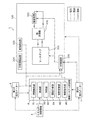
- FIG. 2 is a detailed configuration diagram of heat pump heating device 100 and heating system control unit 8 according to Embodiment 1 of the present invention.
- the heat pump 101 is an air heat source heat pump and compresses a refrigerant (for example, R410A) to a high temperature and high pressure state.
- the heat exchanger 102 includes a refrigerant that has been heated to a high temperature and a high pressure by the heat pump 101, and a secondary water cycle that is filled with water (that is, water that circulates between the heat exchanger 102 and the heating device 103). Heat exchange between them.
- the heating device 103 is a device for heating the home, and is, for example, a radiator or floor heating that releases thermal energy into the room through a heat dissipation panel.
- the specific example of the heating apparatus 103 is not limited to these, All apparatuses which have a thermal radiation part which discharge
- the outside air temperature detection unit 104 is installed outside the room and detects the outside air temperature with a thermostat or the like.
- the room temperature detector 105 is installed indoors and detects the temperature of the room with a thermostat or the like.
- the room temperature detection unit 105 is an example of a temperature detection unit that measures the temperature of an object (in this case, the room), and is not limited to this.
- a temperature detection unit that detects the temperature of the floor (target) may be used instead of the room temperature detection unit 105.
- the HP control unit 106 controls the amount of heat released from the heating device 103 and the amount of raw heat from the heat pump 101 so that the room temperature of the room in which the heating device 103 is installed is maintained within a predetermined range including the set temperature. To do. Note that the HP control unit 106 controls the operations of the heat pump 101 and the heating device 103 according to, for example, operating conditions set by the user in a normal state (a state in which the pre-shutoff signal is not received). On the other hand, the HP control unit 106 controls the operations of the heat pump 101 and the heating device 103 in accordance with instructions from the heating system control unit 8 in the time zones before and after the shut-off time zone.
- the heating system control unit 8 includes a state detection unit 81, a communication unit 82, a prediction unit 83, an operation planning unit 84, a control switching unit 85, a control command unit 86, and the like.
- the heating system control unit 8 is configured separately from the heat pump heating device 100.
- the heat pump heating device 100 and the heating system control unit 8 may be configured as an integral unit, for example, the heating system control unit 8 may be disposed at the position of the HP control unit 106.
- the state detection unit 81 includes an amount of heat released from the heating device 103 to each room from various signals detected by the outside air temperature detection unit 104 and the room temperature detection unit 105, and the first and second power meters 6 and 7. Various information such as the measured power consumption is detected (collected).
- the communication unit 82 receives the pre-shutoff signal and the on signal from the energy supplier 4 and informs the energy supplier 4 that the supply of power to the heat pump heating device 100 through the second power system is cut off or resumed. It has a function to notify The pre-shutoff signal received by the communication unit 82 is a signal indicating that the supply of power through the second power system is stopped after a predetermined time has elapsed.
- This pre-shutoff signal includes information for specifying a “shutoff time zone”, which is a time zone in which power supply through at least the second power system is stopped.
- a “shutoff time zone” is a time zone in which power supply through at least the second power system is stopped.
- the shut-off time zone in the example described below is one hour from 18:00 to 19:00.
- the prior shut-off signal may include information indicating an allowable peak power in a time zone before and after the shut-off time zone.
- the allowable peak power in the example described below is 4.5 kW.
- the prediction unit 83 calculates the amount of heat necessary for heating in the shut-off time zone, and the time zones before and after the shut-off time zone. And an algorithm for predicting the transition of the amount of room temperature decrease in the shut-off time zone. A specific prediction method will be described later.
- the operation planning unit 84 is, for example, a time zone before and after the shut-off time zone based on the predicted value predicted by the prediction unit 83 at the timing when the communication unit 82 receives the pre-shutoff signal from the energy supplier 4.
- the operation plan of the heat pump type heating device 100 is made.
- the control switching unit 85 gives priority to the independent control by the HP control unit 106 in the heat pump heating device 100 when the communication unit 82 has not received a pre-shutoff signal from the energy supplier 4.
- the operation plan unit 84 creates and makes the HP control unit 106 control each component described above according to the operation plan notified from the control command unit 86.
- the control command unit 86 transmits the operation plan set by the operation plan unit 84 to the HP control unit 106 of the heat pump heating device 100.
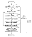
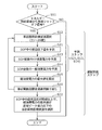
- FIG. 3 is a flowchart of a process for creating an operation plan of the heat pump heating device 100 performed by the operation planning unit 84 and the prediction unit 83 according to Embodiment 1 of the present invention.
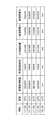
- FIG. 4A is a table showing an example of a prediction result of power consumption when the prior heat storage target room temperature is 24 ° C.
- FIG. 4B is a table showing a calculation result of the maximum value of the total power consumption for each prior heat storage target room temperature.
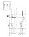
- FIG. 5A is a graph showing changes in HP output heat amount and room temperature for each prior heat storage target room temperature predicted by the prediction unit 83.
- FIG. 5B is a graph showing the transition of power consumption for each prior heat storage target room temperature predicted by the prediction unit 83.
- the amount of heat to be radiated from the heating device 103 in the shut-off time zone (hereinafter referred to as “SOP heat amount”) in order to maintain the room temperature at the set temperature is referred to as the shut-off time zone.
- SOP heat amount the amount of heat to be radiated from the heating device 103 in the shut-off time zone
- This is an operation plan for adding heat to the heat pump 101 and generating heat in the time zones before and after (hereinafter, referred to as “preliminary accumulation period” and “post-accumulation period”). More specifically, the operation planning unit 84 determines the SOP heat amount so that the maximum power consumption in each of the preliminary product period and the post product period is equal to or less than the allowable peak power. Create an operation plan to distribute and heat up the period.
- the operation plan unit 84 starts creating an operation plan at the timing when the communication unit 82 receives the pre-shutoff signal from the energy supplier 4 (YES in S11).
- the timing of the operation plan creation is not limited to this, and may be started at a predetermined time (for example, midnight), for example. However, in this case, it is necessary to know the shut-off time zone of the day.
- the operation planning unit 84 selects a pre-heat storage target room temperature (pre-heat storage target temperature) (S12).
- This pre-heat storage target room temperature is the room temperature at the start of the shut-off time zone.
- the example of FIG. 3 shows a case where the selection is made in increments of 1 degree from the range of 21 degrees to 24 degrees.
- the prediction unit 83 uses the power consumption consumed by the heat pump 101 (hereinafter referred to as “HP power consumption”) in each of the prior accumulation period and the subsequent accumulation period from the outside air temperature and room temperature information detected by the state detection unit 81. ”Is predicted (S13). This predicted value depends on the capacity of the heat pump (rated output, COP), the capacity of the heating device 103, and the house performance (such as heat dissipation loss).
- the HP power consumption predicted in step S13 is the heat consumption power consumed by the heat pump 101 in order to maintain the room at the set temperature in each of the pre-product period and the subsequent product period (in FIG. 4A). Power required to generate the amount of heat corresponding to the amount of heat maintained at room temperature) and the amount of power consumed for heating the distributed SOP heat amount by the heat pump 101 (the amount of heat corresponding to the amount of room temperature heating in FIG. 4A). And the time change of the total value).
- the prediction unit 83 predicts the transition of general power consumption (S14).
- the general power consumption estimated in step S14 is a time change of the power consumed by apparatuses (in the example of FIG. 1, electric power load 5) other than the heat pump heating device 100.
- the operation planning unit 84 calculates the maximum value of the total power consumption in each of the prior product period and the subsequent product period based on these predicted values (S15). Note that the total power consumption calculated in step S15 is a change over time in the total value of the raw heat power consumption, the accumulated power consumption, and the general power consumption predicted in steps S13 to S14.
- FIG. 4A shows numerical changes in time, room temperature (° C.), room temperature maintenance heat (W), room temperature heating heat (W), HP power consumption (W), general power consumption (W), and total power consumption (W).
- FIG. 4A shows numerical changes in time, room temperature (° C.), room temperature maintenance heat (W), room temperature heating heat (W), HP power consumption (W), general power consumption (W), and total power consumption (W).
- the room temperature at 17:00 is the set temperature of 20 ° C.
- the temperature of the heat pump heating device 100 is set so that the room temperature becomes this temperature (20 ° C.) except for the three periods of the advance accumulation period, the shut-off period, and the subsequent accumulation period. Then, the room temperature starts to rise gradually from 17:00, and the room temperature rises to 21 ° C. at 17:15, 15 minutes later. Similarly, the temperature reaches 22 ° C. at 17:30, 23 ° C. at 17:45, and reaches the target preliminary heat storage target temperature of 24 ° C. at 18:00. That is, FIG.
- 4A shows the room temperature from the set temperature (20 ° C.) to the pre-heat storage target room temperature (24 ° C.) at a rate of 1 ° C. every 15 minutes during 1 hour (preliminary overlay period) from 17:00 to 18:00. An example of raising is shown.
- the amount of heat required to raise the room temperature from 20 ° C. to 21 ° C. in 15 minutes from 17:00 to 17:15 is the “room temperature maintaining heat amount” necessary to maintain the room temperature at 20 ° C. This is the sum of the "heat amount at room temperature” required to increase the temperature.
- the room temperature maintenance calorie can be calculated by Equation 1
- Room temperature maintenance heat amount (room temperature-outside air temperature) x heat insulation performance x room surface area (1)
- Room temperature heating amount temperature change amount ⁇ specific air heat ⁇ room volume / heating time (Equation 2)
- the HP power consumption can be calculated by Equation 3 as the HP power consumption consumed by the heat pump 101 to regenerate the room temperature heating heat and the room temperature maintenance heat. That is, the HP power consumption for 15 minutes from 17:00 to 17:15 is 2249 W.
- HP power consumption (room temperature heating amount + room temperature maintaining amount) / COP (Equation 3)
- the general power consumption which is the power consumption of home appliances (power load 5), consumed from 17 o'clock to 15:15 at 17:15 is 1640W.
- the prediction method of general power consumption is not specifically limited, For example, what is necessary is just to predict based on the track record of the past power consumption.
- the power consumption measured by the first power meter 6 is periodically collected and accumulated by the state detection unit 81. Then, the average value of past power consumption results (for example, three results of one week ago, two weeks ago, and three weeks ago) on the same day of the week as the time zone to be predicted and the same time is used as the predicted value. That's fine.
- the total power consumption from 17:15 to 17:30 for 15 minutes is 3909 W
- the total power consumption from 17:30 to 17:45 is 3769 W
- the total power consumption from 17:45 to 18:15 is 15 minutes.
- the total power consumption is 4000W.
- the maximum value of the total power consumption in the prior product period from 17:00 to 18:00 is 4000 W (4 kW).
- the transition of total power consumption during the subsequent period can be calculated.
- it corresponds to the sum of “room temperature maintenance heat amount” required to maintain the room temperature at the end of the shut-off time period and “room temperature heating energy” required to raise the room temperature to the set temperature.
- the power consumed by the heat pump 101 in order to generate the amount of heat is defined as HP power consumption.
- the room temperature at the end of the shut-off period is 18 ° C. and the room temperature is increased over 30 minutes by 1 ° C. every 15 minutes to the set temperature of 20 ° C.
- the room temperature maintenance heat amount and the room temperature heating heat amount every 15 minutes are calculated using Equation 2, and the maximum value of the total power consumption can be calculated using these.
- the prior overlay period is 1 hour and the subsequent overlay period is 30 minutes, but this time can be arbitrarily changed.
- the longer the time the smaller the peak of power consumption, but the heat dissipation loss increases and the power consumption increases.
- the shorter the time the smaller the heat dissipation loss, but the higher the power consumption peak.
- the time is too short, a rapid temperature change occurs, which impairs user comfort.
- the length of the overlay period may be changed according to the temperature change amount. That is, the higher the pre-heat storage target room temperature, the longer the prior overlay period, and the greater the difference between the predicted value of the room temperature at the end of the shut-off time zone and the set temperature, the longer the subsequent overlay period. By doing so, it is possible to avoid increasing the peak of power consumption without impairing the comfort of the user.
- the operation planning unit 84 stores the maximum value of the total power consumption calculated in step S15 for each selected prior heat storage target room temperature, and repeats a series of operations (S12 to S15) (S16). As a result, as shown in FIG. 4B, for example, a list of maximum values of total power consumption for each prior heat storage target room temperature is obtained. Note that the “maximum value of total power consumption” in the rightmost column of FIG. 4B indicates the maximum value of total power consumption throughout the prior product period and the subsequent product period.
- the operation planning unit 84 selects a prior heat storage target room temperature at which the maximum value of the total power consumption is equal to or less than the allowable peak power (S17). For example, assuming that the allowable peak power is 4.5 kW, the maximum value of the total power consumption is 23 ° C. and 24 ° C. among the prior heat storage target room temperatures shown in FIG. 4B. And the operation plan part 84 in Embodiment 1 selects 24 degreeC with the smallest maximum value of total power consumption.
- control command unit 86 HP operates the operation plan for the prior product period and the subsequent product period created by the operation plan unit 84 (for example, the table in FIG. 4A corresponds to the operation plan for the prior product period). Notify the control unit 106. Then, the HP control unit 106 controls the operation of the heat pump 101 according to the acquired operation plan.
- the HP control unit 106 determines that the room temperature of the room in which the heating device 103 is installed is 1 hour from 15 o'clock to 18 o'clock, which is a prior product period, and 1 ° C. every 15 minutes for a total of 4 ° C.
- the operation of the heat pump 101 and the heating device 103 is controlled so as to rise. That is, in this one hour, the preset temperature is changed from 20 ° C. to 24 ° C., which is the pre-heat storage target room temperature.
- the HP controller 106 increases the room temperature of the room in which the heating device 103 is installed by 2 ° C. in 1 minute increments every 15 minutes from 19 o'clock 30 minutes, 19 o'clock, which is the subsequent product period.
- the operation of the heat pump 101 and the heating device 103 is controlled. That is, in this 30 minutes, the room temperature is restored from 18 ° C. at the end of the shut-off period to 20 ° C. which is the set temperature.
- the HP output heat amount, the room temperature, and the total power consumption change according to the prediction results shown in FIGS. 5A and 5B.
- the HP output heat amount, the room temperature, and the total power consumption monotonously increase so that the room temperature at the end of the prior overlay period reaches the prior heat storage target room temperature.
- the HP output heat amount becomes 0 (that is, the heat pump 101 is stopped), the room temperature monotonously decreases, and the power consumption is only the general power consumption.
- the HP output heat amount, the room temperature, and the total power consumption monotonically increase so that the room temperature at the end of the subsequent accumulation period reaches the set temperature.
- the transition of HP output heat quantity, room temperature, and total power consumption shows the same tendency regardless of which pre-heat storage target room temperature is selected, but as the pre-heat storage target room temperature becomes higher as shown in FIGS. 5A and 5B.
- the temperature that should be raised during the prior accumulation period is increased, the HP output heat amount is increased, and the HP power consumption is increased.
- the heat pump 101 stops in the shut-off time period, and the heat radiation from the heating device 103 is interrupted, so that the room temperature decreases.
- the room temperature at the end of the shut-off time zone becomes higher as the prior heat storage target room temperature is higher.
- the higher the pre-heat storage target room temperature the smaller the HP output heat amount and HP power consumption for returning the room temperature to the set temperature during the subsequent accumulation period.
- the maximum value of the total power consumption in the time zones before and after the shut-off time zone can be leveled below the allowable peak power.
- Embodiment 1 the transition of the total power consumption is predicted for each prior heat storage target room temperature, and the prior heat storage target room temperature that allows the maximum value of the total power consumption to be equal to or less than the allowable peak power is selected.
- the room temperature is greatly lowered due to heat radiation during the shut-off time period, and the comfort of the user of the heat pump heating device 100 is impaired.
- the transition of the room temperature decrease amount in the shut-off time zone is further predicted, and the maximum value of the total power consumption is set while maintaining the room temperature that does not impair the comfort of the user of the heat pump heating device 100. Take a method that falls within the allowable peak power.
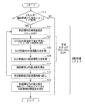
- FIG. 6 is a flowchart of a process for creating an operation plan of the heat pump heating device 100 performed by the operation planning unit 84 and the prediction unit 83 according to Embodiment 2 of the present invention.
- FIG. 7 is a table showing the calculation result of the maximum value of the total power consumption for each prior heat storage target room temperature.
- Steps S12, S13, S14, S15, and S16 in FIG. 6 perform the same functions as those in the first embodiment (FIG. 3).
- the operation planning unit 84 has a plurality of prior heat storage targets in which the maximum value of the total power consumption is equal to or less than the allowable peak power as shown in FIG. Of room temperature (23 ° C., 24 ° C., 25 ° C.), 25 ° C. at which the lowest room temperature in the shut-off time zone is not less than the allowable room temperature is selected.
- the prior heat storage target with the smallest total power consumption is the smallest. Room temperature may be selected.
- the maximum value of power consumption does not exceed the allowable peak power, and A pre-heat storage target room temperature that does not fall below an allowable room temperature can be selected.
- the maximum value of the power consumption in the time zone before and after the shut-off time zone can be leveled below the allowable peak power while maintaining a room temperature that does not impair the comfort of the user of the heat pump heating device 100.
- Embodiment 3 Since the configuration of the heat pump heating system 1 according to Embodiment 3 is the same as that of Embodiment 1, description thereof is omitted. Further, detailed description of points common to the first and second embodiments will be omitted, and the description will be focused on the differences.
- the pre-heat storage target room temperature that minimizes the maximum power consumption is selected within a range that does not fall below the allowable room temperature.
- the optimal control is not necessarily performed.
- Embodiment 3 the transition of the room temperature decrease amount in the shut-off time zone is predicted for each prior heat storage target room temperature, and the shut-off time that does not impair the comfort of the user of the heat pump heating device 100 is determined. Then, the maximum value of the total power consumption is compared.
- FIG. 8 is a flowchart of a process for creating an operation plan of the heat pump heating device 100 performed by the operation planning unit 84 and the prediction unit 83 according to Embodiment 3 of the present invention.
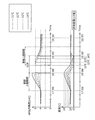
- FIG. 9A is a graph showing the HP output heat amount and room temperature transition predicted by the prediction unit 83 for each prior heat storage target room temperature.
- FIG. 9B is a graph showing the transition of power consumption for each prior heat storage target room temperature predicted by the prediction unit 83.
- FIG. 10 is a table showing the calculation result of the maximum value of the total power consumption for each prior heat storage target room temperature.
- steps S12, S13, S14, S15, and S16 in FIG. 8 perform the same functions as those in the first embodiment (FIG. 3).
- the heat pump heating system according to Embodiment 3 can restart the power supply to the heat pump 101 before the shut-off time period indicated by the prior shut-off signal ends.
- the heat pump 101 operates by receiving power supply from the energy supplier 4 through the first system until the original end time of the shut-off time zone.
- the prediction unit 83 predicts the transition of the room temperature decrease amount in the shut-off time zone, and determines the shut-off time.
- the shut-off time is a time during which the room temperature decreases from the pre-heat storage target temperature to the threshold temperature (allowable room temperature), and can be rephrased as the time during which the power supply to the heat pump 101 is actually stopped. .
- step S32 the operation planning unit 84 selects a pre-heat storage target temperature in consideration of the shut-off time from among a plurality of pre-heat storage target temperatures whose maximum total power consumption is equal to or less than the allowable peak power.
- the operation plan unit 84 may determine the prior heat storage target room temperature in consideration of the balance between the maximum value of the total power consumption and the reduction width of the shut-off time zone. For example, when the allowable room temperature is 18 ° C. and the allowable peak power is 4.5 kW, the operation planning unit 84 has a plurality of prior heat storage targets in which the maximum value of the total power consumption is equal to or lower than the allowable peak power as shown in FIG. Of room temperature (21 ° C., 22 ° C., 23 ° C., 24 ° C., 25 ° C., 26 ° C.), 23 ° C. having the smallest total power consumption may be selected.
- the selection method of the prior heat storage target room temperature is not limited to this, and the operation planning unit 84 selects 25 ° C. that can maximize the shut-off time among a plurality of prior heat storage target room temperatures that satisfy the allowable peak power condition. You may do it.
- the heating system control part 8 makes the heat pump 101 restart a raw heat before the original shut-off time slot
- the heating system control unit 8 uses the heat pump 101 to calculate the amount of SOP heat distributed in the subsequent product period at the timing when the shut-off time corresponding to the pre-heat storage target temperature selected from the start of the shut-off time zone has elapsed. Overheat and heat up. That is, as shown in FIG. 9A and FIG. 9B, the end time of the shut-off time zone and the start and end times of the subsequent overlay period in Embodiment 3 vary depending on the selected pre-heat storage target room temperature.
- the transition of the room temperature decrease amount and the total power consumption is predicted for each prior heat storage target room temperature, and the shut-off time that does not fall below the allowable room temperature is predicted.
- the maximum value of the total power consumption in the time zones before and after the shut-off time zone can be leveled below the allowable peak power while maintaining the room temperature that does not impair the comfort of the user of the device 100.
- Embodiments 1, 2, and 3 the description has been made on the assumption that the allowable peak power is notified from the energy supplier 4, but it may be set by the following method.
- the user may register / set allowable peak power in the heating system control unit 8 for each house.
- FIG. 11 is a diagram showing the correspondence between the heating supply area and the allowable peak power. If the room has a heating supply area of 50 m 2, the allowable peak power is set to 4 kW. In this way, the allowable peak power may be set according to the floor area to which heating is supplied.
- FIG. 12 is a diagram showing the correspondence between the rated output of the heat pump heater and the allowable peak power. If the rated output is 6 kW, the allowable peak power is set to 4 kW. As described above, a method of setting the allowable peak power according to the rated output of the heat pump heating device 100 may be taken.
- the energy supplier 4 may include the list of allowable peak power corresponding to the floor area as shown in FIG. 11 in the pre-shutoff signal and transmit it to the heating system control unit 8. Then, the heating system control unit 8 acquires the floor area of the room in which the heating device 103 is installed, and selects the allowable peak power corresponding to the acquired floor area from the list included in the pre-shutoff signal. May be.
- the energy supplier 4 may include the list of allowable peak power corresponding to the rated output as shown in FIG. 12 in the pre-shutoff signal and transmit it to the heating system control unit 8.
- the heating system control part 8 may acquire the rated output of the heat pump type heating apparatus 100, and may make it select the allowable peak electric power corresponding to the acquired rated output from the list
- the optimum allowable peak power is predicted from the outside air temperature and the current room temperature information, and is set in the heating system control unit 8. You may make it do. Accordingly, it is possible to set an appropriate allowable peak power based on environmental information such as the outside temperature and room temperature information at the start of the shut-off time period. Thereby, leveling of power consumption can be realized within the allowable room temperature range where comfort can be maintained.
- the allowable peak power is treated as a fixed value in time, that is, through the prior product period and the subsequent product period, but may be varied with time as follows.
- the permissible peak power during the posterior product period may be set individually so as to be smaller than the permissible peak power during the prior product period. This is because when the forecast error of household power demand and heating load is taken into consideration, the predicted value of total power consumption during the subsequent product period may be larger than the predicted value of total power consumption during the previous product period. Is expensive. Therefore, by estimating the allowable peak power during the subsequent product period to be smaller, it is possible to reduce the amount of increase in peak power due to the deviation between the predicted value of peak power and the actual value.
- Each of the above devices is specifically a computer system including a microprocessor, ROM, RAM, a hard disk unit, a display unit, a keyboard, a mouse, and the like.
- a computer program is stored in the RAM or the hard disk unit.
- Each device achieves its functions by the microprocessor operating according to the computer program.
- the computer program is configured by combining a plurality of instruction codes indicating instructions for the computer in order to achieve a predetermined function.
- the system LSI is a super multifunctional LSI manufactured by integrating a plurality of components on a single chip, and specifically, a computer system including a microprocessor, a ROM, a RAM, and the like. .
- a computer program is stored in the RAM.
- the system LSI achieves its functions by the microprocessor operating according to the computer program.
- the constituent elements constituting each of the above devices may be constituted by an IC card or a single module that can be attached to and detached from each device.
- the IC card or module is a computer system that includes a microprocessor, ROM, RAM, and the like.
- the IC card or the module may include the super multifunctional LSI described above.
- the IC card or the module achieves its functions by the microprocessor operating according to the computer program. This IC card or this module may have tamper resistance.
- the present invention may be the method described above. Further, the present invention may be a computer program that realizes these methods by a computer, or may be a digital signal composed of a computer program.
- the present invention also relates to a computer-readable recording medium capable of reading a computer program or a digital signal, such as a flexible disk, hard disk, CD-ROM, MO, DVD, DVD-ROM, DVD-RAM, BD (Blu-ray Disc), It may be recorded in a semiconductor memory or the like. Further, it may be a digital signal recorded on these recording media.
- a computer-readable recording medium capable of reading a computer program or a digital signal, such as a flexible disk, hard disk, CD-ROM, MO, DVD, DVD-ROM, DVD-RAM, BD (Blu-ray Disc), It may be recorded in a semiconductor memory or the like. Further, it may be a digital signal recorded on these recording media.
- the present invention may transmit a computer program or a digital signal via an electric communication line, a wireless or wired communication line, a network represented by the Internet, a data broadcast, or the like.
- the present invention may be a computer system including a microprocessor and a memory.
- the memory may store the computer program, and the microprocessor may operate according to the computer program.
- program or digital signal may be recorded on a recording medium and transferred, or the program or digital signal may be transferred via a network or the like, and may be implemented by another independent computer system.
- the heat pump heating system and the control method thereof according to the present invention are useful as a heating system that contributes to stabilization of system power.
Landscapes
- Engineering & Computer Science (AREA)
- Physics & Mathematics (AREA)
- General Engineering & Computer Science (AREA)
- Thermal Sciences (AREA)
- Chemical & Material Sciences (AREA)
- Combustion & Propulsion (AREA)
- Mechanical Engineering (AREA)
- Power Engineering (AREA)
- Computer Hardware Design (AREA)
- Automation & Control Theory (AREA)
- General Physics & Mathematics (AREA)
- Steam Or Hot-Water Central Heating Systems (AREA)
- Heat-Pump Type And Storage Water Heaters (AREA)
- Central Heating Systems (AREA)
Abstract
ヒートポンプ式暖房システム(1)は、エネルギー供給業者(4)から供給される電力を用いて熱を生成するヒートポンプ(101)と、ヒートポンプ(101)で生成された熱を対象に放熱する暖房装置(103)と、ヒートポンプ(101)にシャットオフ時間帯の生熱を停止させると共に、対象を設定温度に維持するためにシャットオフ時間帯に暖房装置(103)から放熱されるべき熱量であるSOP熱量を、シャットオフ時間帯の前後の時間帯にヒートポンプ(101)に上積みして生熱させる暖房システム制御部(8)とを備え、暖房システム制御部(8)は、シャットオフ時間帯の前後の時間帯それぞれにおける消費電力の最大値が共に許容ピーク電力以下となるように、SOP熱量をシャットオフ時間帯の前後の時間帯に分配して生熱させる。
Description
本発明は暖房システム、特にヒートポンプ式暖房システムに関するものである。
欧州の一部の国(ドイツなど)におけるエネルギー供給業者は、電力負荷の平準化を目的として、顧客との契約において1日に所定の期間(以降、「シャットオフ時間帯」と呼ぶ)、所定の回数だけヒートポンプ式暖房システムの電源を外部から強制的に遮断(以降、「シャットオフ」と呼ぶ)することを許容することの代替として、安価な電力料金を提供している。
このため、ヒートポンプ式暖房システムの製造業者においては、上記外部からの制御に対応するため、エネルギー供給業者からのリップル信号を受信すると電源がオンまたはオフとなるリレースイッチを備えている。
しかしながら、上記制御方式では、エネルギー供給業者からのシャットオフ信号を受信すると、ヒートポンプ式暖房システムは直ちに運転を停止する。このため、時間の経過と共に室温が低下して、使用者の快適性を損なう恐れがある。特に、蓄熱タンクや住宅の躯体に十分に蓄熱しない状態で電源がオフされると、室温の低下が著しく、使用者の快適性を損なう。このことは、特に断熱性能の低い住宅にヒートポンプ式暖房システムを導入する際に問題となる。
そこで、本発明は、上記の事情に鑑みてなされたものであり、シャットオフ信号によって電力の供給が一時的に停止する期間に必要となる熱を適切に蓄熱することができるヒートポンプ式暖房システム及びその制御方法を提供することを目的とする。
本発明の一形態に係る暖房システムは、電力供給元から電力の供給を受けて、対象の温度を予め定められた設定温度を含む所定の温度範囲に維持する。具体的には、前記電力供給元から供給される電力を用いて熱を生成するヒートポンプ部と、前記ヒートポンプ部で生成された熱を対象に放熱する放熱部と、前記ヒートポンプ部に予め定められたシャットオフ時間帯の生熱を停止させると共に、対象を前記設定温度に維持するために前記シャットオフ時間帯に前記放熱部から放熱されるべき熱量であるSOP熱量を、前記シャットオフ時間帯の前後の時間帯に前記ヒートポンプ部に上積みして生熱させる暖房システム制御部とを備える。そして、前記暖房システム制御部は、前記シャットオフ時間帯の前後の時間帯それぞれにおける消費電力の最大値が共に許容ピーク電力以下となるように、前記SOP熱量を前記シャットオフ時間帯の前後の時間帯に分配して生熱させる。
なお、これらの全般的または具体的な態様は、システム、方法、集積回路、コンピュータプログラムまたは記録媒体で実現されてもよく、システム、方法、集積回路、コンピュータプログラムおよび記録媒体の任意な組み合わせで実現されてもよい。
本発明によれば、シャットオフ時間帯の前後の時間帯の消費電力の最大値が共に許容ピーク電力以下となるように、SOP熱量を分配して生熱させるので、快適性だけでなく、シャットオフ時間帯の前後の時間帯における電力ピークをも平準化することができる。
本発明の一形態に係る暖房システムは、電力供給元から電力の供給を受けて、対象の温度を予め定められた設定温度を含む所定の温度範囲に維持する。具体的には、前記電力供給元から供給される電力を用いて熱を生成するヒートポンプ部と、前記ヒートポンプ部で生成された熱を対象に放熱する放熱部と、前記ヒートポンプ部に予め定められたシャットオフ時間帯の生熱を停止させると共に、対象を前記設定温度に維持するために前記シャットオフ時間帯に前記放熱部から放熱されるべき熱量であるSOP熱量を、前記シャットオフ時間帯の前後の時間帯に前記ヒートポンプ部に上積みして生熱させる暖房システム制御部とを備える。そして、前記暖房システム制御部は、前記シャットオフ時間帯の前後の時間帯それぞれにおける消費電力の最大値が共に許容ピーク電力以下となるように、前記SOP熱量を前記シャットオフ時間帯の前後の時間帯に分配して生熱させる。
上記構成のように、シャットオフ時間帯に放熱されるべきSOP熱量を、その前後の時間帯に分配して生熱することにより、シャットオフ時間帯の前後の時間帯における消費電力のピークを抑えた暖房システムを得ることができる。
さらに、前記暖房システム制御部は、前記シャットオフ時間帯の前後の時間帯それぞれにおいて、対象を前記設定温度に維持するために前記ヒートポンプ部で消費される生熱消費電力の推移と、分配された前記SOP熱量を前記ヒートポンプ部で生熱するのに必要な上積消費電力の推移と、該暖房システム以外の機器で消費される一般消費電力の推移とを予測する予測部と、前記シャットオフ時間帯の前後の時間帯それぞれにおいて、前記一般消費電力と前記生熱消費電力と前記上積消費電力との合計である総消費電力の最大値が共に前記許容ピーク電力以下となるように、前記SOP熱量を分配して生熱させるための運転計画を作成する運転計画部とを備えてもよい。そして、前記暖房システム制御部は、前記運転計画部で作成された運転計画に基づいて、前記ヒートポンプを制御する。
また、前記シャットオフ時間帯の前の時間帯における前記上積消費電力は、前記シャットオフ時間帯の開始時点において、前記対象の温度を前記設定温度より高い事前蓄熱目標温度まで上昇させるために、前記ヒートポンプ部で消費される消費電力であってもよい。同様に、前記シャットオフ時間帯の後の時間帯における前記上積消費電力は、前記シャットオフ時間帯の終了時点における対象の温度を前記設定温度まで上昇させるために、前記ヒートポンプ部で消費される消費電力であってもよい。さらに、前記暖房システム制御部は、対象の温度及び外気温を検出する検出部を備えてもよい。そして、前記予測部は、前記検出部の検出結果に基づいて、前記シャットオフ時間帯の前後の時間帯それぞれの前記上積消費電力の推移を予測してもよい。
また、前記運転計画部は、前記シャットオフ時間帯の前後の時間帯それぞれの前記総消費電力の最大値が共に前記許容ピーク電力以下となる複数の前記事前蓄熱目標温度のうち、前記シャットオフ時間帯の前後の時間帯を通しての前記総消費電力の最大値が最小となる前記事前蓄熱目標温度を選択してもよい。これにより、シャットオフ時間帯の前後の時間帯における消費電力のピークを、さらに抑制することができる。
また、前記運転計画部は、前記シャットオフ時間帯の前後の時間帯それぞれの前記総消費電力の最大値が共に前記許容ピーク電力以下となる複数の前記事前蓄熱目標温度のうち、前記シャットオフ時間帯における対象の最低温度が閾値温度以上となる前記事前蓄熱目標温度を選択してもよい。これにより、消費電力のピークを抑制することができると共に、シャットオフ時間帯の温度が閾値温度を下回ることがないので、ユーザの快適性を損なうことを防止できる。
また、前記予測部は、前記複数の事前蓄熱目標温度毎に、対象の温度が当該事前蓄熱目標温度から前記閾値温度まで低下する時間であるシャットオフ時間を予測してもよい。そして、前記暖房システム制御部は、前記シャットオフ時間帯の開始から選択した前記事前蓄熱目標温度に対応する前記シャットオフ時間が経過したタイミングで、前記シャットオフ時間帯の後の時間帯に分配された前記SOP熱量を前記ヒートポンプ部に上積みして生熱させてもよい。これにより、さらに、ユーザの快適性を保つことができる。
さらに、前記運転計画部は、前記複数の事前蓄熱目標温度のうち、前記シャットオフ時間を最大にできる前記事前蓄熱目標温度を選択してもよい。
また、前記運転計画部は、前記シャットオフ時間帯を特定する情報を含む信号を、前記シャットオフ時間帯開始の所定時間前に前記電力供給元から受信したタイミングで、前記運転計画を作成する処理を実行してもよい。
さらに、前記信号には、前記許容ピーク電力を示す情報が含まれてもよい。
また、前記暖房システム制御部は、ユーザから前記許容ピーク電力の入力を受け付けてもよい。
また、前記許容ピーク電力は、該暖房システムが設置される建物の断熱性能に基づいて設定されてもよい。
また、前記シャットダウン時間帯の前の時間帯の前記許容ピーク電力は、前記シャットダウン時間帯の後の時間帯の前記許容ピーク電力より大きくなるように、個別に設定されてもよい。シャットオフ時間帯の前の時間帯における総消費電力の予測値は、シャットオフ時間帯の前の時間帯における総消費電力の予測値よりも予測誤差が高い可能性がある。そこで、シャットオフ時間帯の後の時間帯の許容ピーク電力を相対的に小さく設定することにより、消費電力ピークをより確実に抑制することができる。
また、該暖房システムは、前記ヒートポンプ部と、前記放熱部と、前記暖房システム制御部からの指示に従って、前記ヒートポンプ部を制御するHP制御部とを備える暖房装置と、前記暖房装置とは別体として構成される前記暖房システム制御部とを備えてもよい。
上記構成によれば、暖房装置のみならず、他の機器の制御をも暖房システム制御部に行わせることができる。また、シャットオフに対する制御が必要ない環境で使用する場合には、暖房装置のみを設置すれば足りる。
本発明の一形態に係る暖房システムの制御方法は、電力供給元から電力の供給を受けて、対象の温度を予め定められた設定温度を含む所定の温度範囲に維持する暖房システムを制御する方法である。前記暖房システムは、前記電力供給元から供給される電力を用いて熱を生成するヒートポンプ部と、前記ヒートポンプ部で生成された熱を対象に放熱する放熱部とを備える。暖房システムの制御方法は、前記ヒートポンプ部に予め定められたシャットオフ時間帯の生熱を停止させると共に、対象を前記設定温度に維持するために前記シャットオフ時間帯に前記放熱部から放熱されるべき熱量であるSOP熱量を、前記シャットオフ時間帯の前後の時間帯に前記ヒートポンプ部に上積みして生熱させる暖房システム制御ステップを含む。そして、前記暖房システム制御ステップでは、前記シャットオフ時間帯の前後の時間帯それぞれにおける消費電力の最大値が共に許容ピーク電力以下となるように、前記SOP熱量を前記シャットオフ時間帯の前後の時間帯に分配して生熱させる。
さらに、前記暖房システム制御ステップは、前記シャットオフ時間帯の前後の時間帯それぞれにおいて、対象を前記設定温度に維持するために前記ヒートポンプ部で消費される生熱消費電力の推移と、分配された前記SOP熱量を前記ヒートポンプ部で生熱するのに必要な上積消費電力の推移と、該暖房システム以外の機器で消費される一般消費電力の推移とを予測する予測ステップと、前記シャットオフ時間帯の前後の時間帯それぞれにおいて、前記一般消費電力と前記生熱消費電力と前記上積消費電力との合計である総消費電力の最大値が共に前記許容ピーク電力以下となるように、前記SOP熱量を分配して生熱させるための運転計画を作成する運転計画ステップを含んでもよい。そして、前記暖房システム制御ステップでは、前記運転計画ステップで作成された運転計画に基づいて、前記ヒートポンプを制御してもよい。
また、前記シャットオフ時間帯の前の時間帯における前記上積消費電力は、前記シャットオフ時間帯の開始時点において、前記対象の温度を前記設定温度より高い事前蓄熱目標温度まで上昇させるために、前記ヒートポンプ部で消費される消費電力であってもよい。同様に、前記シャットオフ時間帯の後の時間帯における前記上積消費電力は、前記シャットオフ時間帯の終了時点における対象の温度を前記設定温度まで上昇させるために、前記ヒートポンプ部で消費される消費電力であってもよい。さらに、前記暖房システム制御ステップは、対象の温度及び外気温を検出する検出ステップを含んでもよい。そして、前記予測ステップでは、前記検出ステップでの検出結果に基づいて、前記シャットオフ時間帯の前後の時間帯それぞれの前記上積消費電力の推移を予測してもよい。
また、前記運転計画ステップでは、前記シャットオフ時間帯の前後の時間帯それぞれの前記総消費電力の最大値が共に前記許容ピーク電力以下となる複数の前記事前蓄熱目標温度のうち、前記シャットオフ時間帯の前後の時間帯を通しての前記総消費電力の最大値が最小となる前記事前蓄熱目標温度を選択してもよい。
また、前記運転計画ステップでは、前記シャットオフ時間帯の前後の時間帯それぞれの前記総消費電力の最大値が共に前記許容ピーク電力以下となる複数の前記事前蓄熱目標温度のうち、前記シャットオフ時間帯における対象の最低温度が閾値温度以上となる前記事前蓄熱目標温度を選択してもよい。
また、前記予測ステップでは、前記複数の事前蓄熱目標温度毎に、対象の温度が当該事前蓄熱目標温度から前記閾値温度まで低下する時間であるシャットオフ時間を予測してもよい。そして、前記暖房システム制御ステップでは、前記シャットオフ時間帯の開始から選択した前記事前蓄熱目標温度に対応する前記シャットオフ時間が経過したタイミングで、前記シャットオフ時間帯の後の時間帯に分配された前記SOP熱量を前記ヒートポンプ部に上積みして生熱させてもよい。
さらに、前記運転計画ステップでは、前記複数の事前蓄熱目標温度のうち、前記シャットオフ時間を最大にできる前記事前蓄熱目標温度を選択してもよい。
また、前記運転計画ステップでは、前記シャットオフ時間帯を特定する情報を含む信号を、前記シャットオフ時間帯開始の所定時間前に前記電力供給元から受信したタイミングで、前記運転計画を作成する処理を実行してもよい。
なお、これらの全般的または具体的な態様は、システム、方法、集積回路、コンピュータプログラムまたは記録媒体で実現されてもよく、システム、方法、集積回路、コンピュータプログラムまたは記録媒体の任意な組み合わせで実現されてもよい。
以下本発明の実施の形態について、図面を参照しながら説明する。
なお、以下で説明する実施の形態は、いずれも本発明の一具体例を示すものである。以下の実施の形態で示される数値、形状、材料、構成要素、構成要素の配置位置及び接続形態、ステップ、ステップの順序などは、一例であり、本発明を限定する主旨ではない。また、以下の実施の形態における構成要素のうち、最上位概念を示す独立請求項に記載されていない構成要素については、任意の構成要素として説明される。
(実施の形態1)
図1は、本発明の実施の形態1に係るヒートポンプ式暖房システム1を示す図である。図1に示される例では、エネルギー供給業者(電力供給元)4から住宅(建物)に対して、第1及び第2の電力系統を通じて電力が供給されている。第1の電力系統は、安定的に電力が供給される電力系統である。また、第1の電力系統は、電力料金が相対的に高い電力系統であり、第1の電力メーター6によって電力消費量が計測される。一方、第2の電力系統は、エネルギー供給業者4によって任意の時間帯に電力の供給を停止することができる電力系統である。また、第2の電力系統は、電力料金が第1の電力系統よりも廉価な電力系統であり、第2の電力メーター7によって電力消費量が計測される。
図1は、本発明の実施の形態1に係るヒートポンプ式暖房システム1を示す図である。図1に示される例では、エネルギー供給業者(電力供給元)4から住宅(建物)に対して、第1及び第2の電力系統を通じて電力が供給されている。第1の電力系統は、安定的に電力が供給される電力系統である。また、第1の電力系統は、電力料金が相対的に高い電力系統であり、第1の電力メーター6によって電力消費量が計測される。一方、第2の電力系統は、エネルギー供給業者4によって任意の時間帯に電力の供給を停止することができる電力系統である。また、第2の電力系統は、電力料金が第1の電力系統よりも廉価な電力系統であり、第2の電力メーター7によって電力消費量が計測される。
また、図1に示される住宅内には、電力負荷5と、暖房システム制御部8と、ヒートポンプ式暖房装置100とが設置されている。ヒートポンプ式暖房装置100は、ヒートポンプ(生熱部)101と、熱交換器102と、暖房装置(放熱部)103とを少なくとも備えている。
ヒートポンプ式暖房装置100は、ヒートポンプ101で生成した熱を、熱交換器102を通じて暖房装置103から放熱することにより、暖房装置103が設置されている部屋の室温を予め定められた設定温度を含む所定の温度範囲内に維持する装置である。なお、所定の温度範囲とは、例えば、事前蓄熱目標室温(後述)を上限、閾値温度(後述)を下限とする範囲である。
第1の電力メーター6は、暖房システム制御部8、及びヒートポンプ式暖房装置100以外の機器(すなわち、電力負荷5)の消費電力を計測するものである。すなわち、暖房システム制御部8及び電力負荷5は、第1の電力系統を通じてエネルギー供給業者4から電力の供給を受けて動作する。一方、第2の電力メーター7は、圧縮機、ポンプ、及びファン等(図示省略)のヒートポンプ式暖房装置100の構成要素の電力消費を計測するものである。すなわち、ヒートポンプ式暖房装置100の各構成要素は、第2の電力系統を通じてエネルギー供給業者4から電力の供給を受けて動作する。
暖房システム制御部8は、エネルギー供給業者4と通信を行う機能を有し、ヒートポンプ式暖房装置100に制御指令を与えるものである。例えば、暖房システム制御部8は、ヒートポンプ式暖房装置100にシャットオフ時間帯の生熱を停止させる。また、暖房システム制御部8は、シャットオフ時間帯の前後の時間帯において、ヒートポンプ式暖房装置100に予め作成された運転計画に基づいて動作させる。
エネルギー供給業者4は、各家庭に電力やガスを供給する会社であり、各家庭の電力の使用を抑制したい場合には、事前にシャットオフ信号(以降、「事前シャットオフ信号」と呼ぶ)を通じて各家庭に通知する。事前シャットオフ信号の通知の時間は、例えば、各家庭の電力の使用を抑制したい時間帯の2時間前などである。
図2は、本発明の実施の形態1に係るヒートポンプ式暖房装置100および暖房システム制御部8の詳細な構成図である。
ヒートポンプ101は、空気熱源のヒートポンプであり、冷媒(例えば、R410A)を圧縮して高温高圧の状態にする。熱交換器102は、ヒートポンプ101で高温高圧にされた冷媒と、水が充填されている二次側の水サイクル(すなわち、熱交換器102と暖房装置103との間で循環する水)との間で熱交換を行う。
暖房装置103は、家庭内を暖めるための装置であり、例えば、放熱パネルを介して室内に熱エネルギーを放出するラジエータや床暖房等である。なお、暖房装置103の具体例はこれらに限定されず、ヒートポンプ101で生成された熱を、対象に放出する放熱部を有するあらゆる装置が該当する。
外気温検出部104は、室外に設置され、外気温をサーモスタットなどで検出する。室温検出部105は、室内に設置され、部屋の温度をサーモスタットなどで検出する。なお、室温検出部105は、対象(この場合は室内)の温度を測定する温度検出部の一例であり、これに限定されない。暖房装置103が床暖房である場合は、室温検出部105に代えて、床面(対象)の温度を検出する温度検出部を用いればよい。
HP制御部106は、暖房装置103が設置されている部屋の室温が設定温度を含む所定の範囲内に維持されるように暖房装置103の放熱量を制御すると共に、ヒートポンプ101の生熱量を制御する。なお、HP制御部106は、通常時(事前シャットオフ信号を受信していない状態)においては、例えば、ユーザによって設定された運転条件等に従って、ヒートポンプ101及び暖房装置103の動作を制御する。一方、HP制御部106は、シャットオフ時間帯の前後の時間帯においては、暖房システム制御部8の指示に従って、ヒートポンプ101及び暖房装置103の動作を制御する。
暖房システム制御部8は、状態検出部81、通信部82、予測部83、運転計画部84、制御切替部85、及び制御指令部86などから構成されている。なお、実施の形態1において、暖房システム制御部8は、ヒートポンプ式暖房装置100とは別体として構成されている。但し、ヒートポンプ式暖房装置100と暖房システム制御部8とを一体として構成、例えば、HP制御部106の位置に暖房システム制御部8を配置してもよい。
状態検出部81は、外気温検出部104、室温検出部105が検出した各種の信号から暖房装置103が各部屋に放出している放熱量や、第1及び第2の電力メーター6、7で計測された消費電力量等の各種情報を検出(収集)するものである。
通信部82は、エネルギー供給業者4からの事前シャットオフ信号やオン信号を受信し、第2の電力系統を通じたヒートポンプ式暖房装置100への電力の供給を遮断または再開した旨をエネルギー供給業者4へと通知する機能を有する。通信部82で受信される事前シャットオフ信号は、第2の電力系統を通じた電力の供給を所定時間経過後に停止することを示す信号である。
この事前シャットオフ信号には、少なくとも第2の電力系統を通じた電力の供給が停止している時間帯である「シャットオフ時間帯」を特定する情報が含まれている。例えば、以下に説明する例におけるシャットオフ時間帯は、18時~19時の1時間である。さらに、事前シャットオフ信号には、シャットオフ時間帯の前後の時間帯における許容ピーク電力を示す情報が含まれていてもよい。例えば、以下に説明する例における許容ピーク電力は、4.5kWである。
予測部83は、状態検出部81により検出した外気温、室温、暖房温度、及び消費電力などの情報に基づいて、シャットオフ時間帯の暖房に必要な熱量、シャットオフ時間帯の前後の時間帯の消費電力、及びシャットオフ時間帯における室温低下量等の推移を予測するアルゴリズムを有する。具体的な予測方法等については、後述する。
運転計画部84は、例えば、通信部82がエネルギー供給業者4から事前シャットオフ信号を受信したタイミングで、予測部83によって予測された予測値をもとに、シャットオフ時間帯の前後の時間帯におけるヒートポンプ式暖房装置100の運転計画を立てるものである。
制御切替部85は、通信部82がエネルギー供給業者4から事前シャットオフ信号を受けていない場合には、ヒートポンプ式暖房装置100内のHP制御部106による自立制御を優先させる。一方、事前シャットオフ信号を受けた際には、運転計画部84が作成し、制御指令部86から通知される運転計画に従って、HP制御部106に前述の各構成要素を制御させる。
制御指令部86は、運転計画部84によって立てられた運転計画を、ヒートポンプ式暖房装置100のHP制御部106に送信する。
次に、図3~図5Bを参照して、実施の形態1に係る暖房システム制御部8の動作を説明する。図3は、本発明の実施の形態1に係る運転計画部84及び予測部83よって行われるヒートポンプ式暖房装置100の運転計画を作成する処理のフローチャートである。図4Aは、事前蓄熱目標室温が24℃の場合における消費電力の予測結果の例を示す表である。図4Bは、事前蓄熱目標室温毎の総消費電力の最大値の算出結果を示す表である。図5Aは、予測部83で予測された事前蓄熱目標室温毎のHP出力熱量及び室温の推移を示すグラフである。図5Bは、予測部83で予測された事前蓄熱目標室温毎の消費電力の推移を示すグラフである。
ここで作成される運転計画は、室温を設定温度に維持するためにシャットオフ時間帯に暖房装置103から放熱されるべき熱量(以下、「SOP熱量」と標記する。)を、シャットオフ時間帯の前後の時間帯(以下、「事前上積期間」及び「事後上積期間」と標記する。)にヒートポンプ101に上積みして生熱させるための運転計画である。より具体的には、運転計画部84は、事前上積期間及び事後上積期間それぞれの消費電力の最大値が共に許容ピーク電力以下となるように、SOP熱量を事前上積期間及び事後上積期間に分配して生熱させるための運転計画を作成する。
運転計画部84は、エネルギー供給業者4からの事前シャットオフ信号を通信部82で受信した(S11でYES)タイミングで、運転計画の作成を開始する。但し、運転計画作成のタイミングは、これに限定されず、例えば、予め定められた時間(例えば、午前0時)に開始してもよい。但し、この場合、当日のシャットオフ時間帯を把握している必要がある。
まず、運転計画部84は、事前蓄熱目標室温(事前蓄熱目標温度)を選択する(S12)。この事前蓄熱目標室温は、シャットオフ時間帯の開始時点における部屋の温度である。図3の例では、21度~24度の範囲から1度刻みで選択される場合を示している。
次に、予測部83は、状態検出部81で検出された外気温及び室温情報等から、事前上積期間及び事後上積期間それぞれにヒートポンプ101で消費される消費電力(以下、「HP消費電力」と標記する。)の推移を予測する(S13)。この予測値は、ヒートポンプの能力(定格出力、COP)および暖房装置103の能力、加えて住宅性能(放熱ロス等)等に依存する。
なお、ステップS13で予測されるHP消費電力とは、事前上積期間及び事後上積期間のそれぞれにおいて、室内を設定温度に維持するためにヒートポンプ101で消費される生熱消費電力(図4Aの室温維持熱量に相当する熱量を生成するのに必要な電力)と、分配されたSOP熱量をヒートポンプ101で生熱するのに必要な上積消費電力(図4Aの室温加熱熱量に相当する熱量を生成するのに必要な電力)との合計値の時間変化である。
さらに、予測部83は、一般消費電力の推移を予測する(S14)。なお、ステップS14で予測される一般消費電力とは、ヒートポンプ式暖房装置100以外の機器(図1の例では、電力負荷5)で消費される電力の時間変化である。
最後に、運転計画部84は、これらの予測値をもとに、事前上積期間及び事後上積期間それぞれの総消費電力の最大値を算出する(S15)。なお、ステップS15で算出される総消費電力とは、ステップS13~S14で予測された生熱消費電力と、上積消費電力と、一般消費電力との合計値の時間変化である。
例えば、図4Aを参照して、事前蓄熱目標室温が24℃の場合における事前上積期間における総消費電力の推移を予測する方法の具体例を説明する。図4Aは、時刻、室温(℃)、室温維持熱量(W)、室温加熱熱量(W)、HP消費電力(W)、一般消費電力(W)、総消費電力(W)の数値変化を示す図である。
ここで、図4Aに示される各予測値は、部屋の容積、部屋の表面積、部屋の空気の比熱、部屋の断熱性能、外気温、及びHPの性能(Coefficient Of Performance)の影響を受ける。そこで、図4Aの例は、部屋の容積を550(m3)、部屋の表面積を600(m2)、空気の比熱を0.34(Wh/℃m3)、部屋の断熱性能を0.5(W/℃m2)、外気温を0(℃)、HPの性能をCOP=3とした場合の予測結果である。
図4Aの例では、時刻17時での室温は設定温度の20℃である。事前上積期間、シャットオフ期間、及び事後上積期間の3つの期間以外は、室温がこの温度(20℃)になるようにヒートポンプ式暖房装置100の温度設定がされている。そして17時から室温が徐々に上昇し始め、15分後の17時15分に室温が21℃に上昇する。同様に、17時30分に22℃、17時45分に23℃となり、18時に目標事前蓄熱目標温度である24℃に達する。すなわち、図4Aは、17時~18時の1時間(事前上積期間)の間に、15分に1℃の割合で設定温度(20℃)から事前蓄熱目標室温(24℃)まで室温を上昇させる例を示している。
17時から17時15分までの15分間で、室温を20℃から21℃に上げるために必要な熱量は、室温を20℃に維持するのに必要な「室温維持熱量」と、室温を1度上昇させるのに必要な「室温加熱熱量」との和となる。
ここで、室温維持熱量は式1で、室温加熱熱量は式2で算出することができる。すなわち、17時から17時15までの15分間に暖房装置103から放熱される熱量は、6000(式1)+748(式2)=6748Wとなる。
室温維持熱量=(室温-外気温)×断熱性能×部屋の表面積・・(式1)
室温加熱熱量=温度変化量×空気の比熱×部屋の容積/加熱時間・・・(式2)
室温加熱熱量=温度変化量×空気の比熱×部屋の容積/加熱時間・・・(式2)
また、HP消費電力は、室温加熱熱量及び室温維持熱量を生熱するためにヒートポンプ101で消費されるHP消費電力は、式3で算出することができる。すなわち、17時から17時15分までの15分間のHP消費電力は、2249Wとなる。
HP消費電力=(室温加熱熱量+室温維持熱量)/COP・・・(式3)
さらに、17時から17時15分の15分間に消費される家電製品(電力負荷5)等の消費電力である一般消費電力は、1640Wである。これにより、17時から17時15の15分間の総消費電力は、2249+1640=3889Wとなる。
なお、一般消費電力の予測方法は特に限定されないが、例えば、過去の消費電力の実績に基づいて予測すればよい。例えば、第1の電力メーター6で計測される消費電力を状態検出部81で定期的に収集し、蓄積しておく。そして、予測しようとする時間帯と同じ曜日で、且つ同じ時刻における過去の消費電力の実績(例えば、1週間前、2週間前、3週間前の3実績)の平均値を、予測値とすればよい。
以下、同様に17時15分から17時30分の15分間の総消費電力は3909W、17時30分から17時45分の15分間の総消費電力は3769W、17時45分から18時の15分間の総消費電力は4000Wとなる。そして、図4Aを参照すれば明らかなように、17時から18時までの事前上積期間における総消費電力の最大値は、4000W(4kW)である。
同様に、事後上積期間における総消費電力の推移も計算することができる。なお、ここでは、シャットオフ時間帯の終了時点における室温を維持するのに必要な「室温維持熱量」と、室温を設定温度まで上昇させるのに必要な「室温加熱熱量」との和に相当する熱量を生成するためにヒートポンプ101で消費される電力をHP消費電力とする。
例えば、シャットオフ期間終了時点における室温が18℃であり、設定温度である20℃まで15分に1℃ずつ、30分かけて室温を上昇させるような場合、運転計画部84は、式1及び式2を用いて15分毎の室温維持熱量及び室温加熱熱量を算出し、これらを用いて総消費電力の最大値を算出することができる。
なお、上記の例では、事前上積期間を1時間、事後上積期間を30分として説明したが、この時間は任意に変更することができる。なお、時間が長くなるほど消費電力のピークは小さくなるが、放熱ロスが大きくなって消費電力量が増加する。一方、時間が短くなるほど放熱ロスは少なくなるが、消費電力のピークは大きくなる。さらに、時間が短すぎると急激な温度変化を生じるので、ユーザの快適性を損なうことになる。
そこで、例えば、温度変化量に応じて上積期間の長さを変えるようにしてもよい。すなわち、事前蓄熱目標室温が高いほど事前上積期間を長くし、シャットオフ時間帯の終了時点における室温の予測値と設定温度との差が大きいほど事後上積期間を長くすればよい。そうすることにより、ユーザの快適性を損なうことなく、また消費電力のピークを大きくなるのを避けることができる。
次に、運転計画部84は、選択した事前蓄熱目標室温毎に、ステップS15で算出した総消費電力の最大値を保存し、一連の動作(S12~S15)を繰り返す(S16)。その結果、例えば図4Bに示されるように、事前蓄熱目標室温毎の総消費電力の最大値の一覧表が得られる。なお、図4Bの右端列の「総消費電力の最大値」には、事前上積期間及び事後上積期間を通しての総消費電力の最大値を示している。
最後に、運転計画部84は、総消費電力の最大値が許容ピーク電力以下となる事前蓄熱目標室温を選択する(S17)。例えば、許容ピーク電力を4.5kWとすると、図4Bに示される事前蓄熱目標室温のうち、総消費電力の最大値が許容ピーク電力以下となるのは23℃及び24℃である。そして、実施の形態1における運転計画部84は、総消費電力の最大値が最も小さい24℃を選択する。
そして、制御指令部86は、運転計画部84で作成された事前上積期間及び事後上積期間の運転計画(例えば、図4Aの表が事前上積期間の運転計画に相当する。)をHP制御部106に通知する。そして、HP制御部106は、取得した運転計画に従ってヒートポンプ101の動作を制御する。
具体的には、すなわち、HP制御部106は、暖房装置103が設置された部屋の室温が、事前上積期間である17時から18時の1時間で、15分に1℃ずつ計4℃上昇するように、ヒートポンプ101及び暖房装置103の動作を制御する。つまりこの1時間で設定温度の20℃から、事前蓄熱目標室温の24℃にする。同様に、HP制御部106は、暖房装置103が設置された部屋の室温が、事後上積期間である19時から19時30分の30分間で、15分に1℃ずつ計2℃上昇するように、ヒートポンプ101及び暖房装置103の動作を制御する。つまりこの30分間で、室温をシャットオフ期間終了時の18℃から、設定温度である20℃に回復させる。
上記のような制御を行うことにより、HP出力熱量、室温、及び総消費電力は、図5A及び図5Bに示される予測結果に沿って推移する。但し、厳密には一致しない可能性がある。具体的には、まず事前上積期間の終了時点での室温が事前蓄熱目標室温に達するように、HP出力熱量、室温、及び総消費電力は単調増加する。次にシャットオフ時間帯(図中「SOP」と標記する。)において、HP出力熱量は0(すなわち、ヒートポンプ101が停止)となり、室温は単調減少し、消費電力は一般消費電力のみとなる。次に、事後上積期間の終了時点での室温が設定温度に達するように、HP出力熱量、室温、及び総消費電力は単調増加する。
HP出力熱量、室温、及び総消費電力の推移は、どの事前蓄熱目標室温を選択しても同様の傾向を示すが、図5A及び図5Bに示されるように、事前蓄熱目標室温が高くなるにつれ、事前上積期間に上昇させるべき温度が高くなり、HP出力熱量が増え、HP消費電力が増加する。一方、シャットオフ時間帯でヒートポンプ101が停止し、暖房装置103からの放熱が途絶えることで、室温は低下していく。そして、シャットオフ時間帯が終了した時点の室温は、事前蓄熱目標室温が高い程高くなる。その結果、事前蓄熱目標室温が高いほど、事後上積期間に室温を設定温度に復帰させるためのHP出力熱量及びHP消費電力は少なくなる。
そこで、本実施の形態1では、事前蓄熱目標室温毎に総消費電力の推移を予測することで、室内を設定温度に維持するためにシャットオフ時間帯に暖房装置103から放熱されるべきSOP熱量を、事前上積期間及び事後上積期間に適切に分配して生熱することができる。その結果、シャットオフ時間帯の前後の時間帯における総消費電力の最大値を、許容ピーク電力以下に平準化することができる。
(実施の形態2)
実施の形態2に係るヒートポンプ式暖房システム1の構成は、実施の形態1と共通するので、再度の説明は省略する。また、実施の形態1との共通点の詳しい説明は省略し、相違点を中心に説明する。
実施の形態2に係るヒートポンプ式暖房システム1の構成は、実施の形態1と共通するので、再度の説明は省略する。また、実施の形態1との共通点の詳しい説明は省略し、相違点を中心に説明する。
実施の形態1においては、事前蓄熱目標室温毎に総消費電力の推移を予測し、総消費電力の最大値を許容ピーク電力以下にすることができる事前蓄熱目標室温を選択した。しかしながら、住宅性能によっては、シャットオフ時間帯の放熱による室温低下が大きく、ヒートポンプ式暖房装置100の使用者の快適性を損なう懸念がある。
そこで、実施の形態2においては、シャットオフ時間帯の室温低下量の推移をさらに予測し、ヒートポンプ式暖房装置100の使用者の快適性を損なわない室温を保ちつつ、総消費電力の最大値を許容ピーク電力以内に収める方法を取る。
図6及び図7を参照して、実施の形態2に係る暖房システム制御部8の動作を説明する。図6は、本発明の実施の形態2に係る運転計画部84及び予測部83よって行われるヒートポンプ式暖房装置100の運転計画を作成する処理のフローチャートである。図7は、事前蓄熱目標室温毎の総消費電力の最大値の算出結果を示す表である。
図3の実施の形態1のフローチャートとの違いとしては、外気温及び室温情報に基づいて、シャットオフ時間帯の室温低下量の推移を予測し、最低室温が許容室温以上であり、かつ、総消費電力の最大値が許容ピーク電力以下となる事前蓄熱目標室温を選択するようにする点である。図6のステップS12、S13、S14、S15、S16は実施の形態1(図3)と同様の機能を果たす。
図6のステップS21において、予測部83は、シャットオフ時間帯における室温低下量の推移を予測し、図7に示すように、事前蓄熱目標室温毎の最低室温(通常は、シャットオフ時間帯の終了時点における室温)を保存する。そして、ステップS22において、運転計画部84は、総消費電力の最大値が許容ピーク電力以下の複数の事前蓄熱目標室温のうち、シャットオフ時間帯の最低室温が閾値温度(許容室温)以上の事前蓄熱目標室温を選択する。
例えば、許容室温を16℃、許容ピーク電力を4.5kWとすると、運転計画部84は、図7に示されるように、総消費電力の最大値が許容ピーク電力以下となる複数の事前蓄熱目標室温(23℃、24℃、25℃)のうち、シャットオフ時間帯における最低室温が許容室温以上となる25℃を選択する。
なお、許容ピーク電力の条件を満たし、且つシャットオフ時間帯における最低室温が許容室温以上となる事前蓄熱目標室温が複数存在する場合には、そのうちの総消費電力の最大値が最も小さい事前蓄熱目標室温を選択してもよい。
このようにして本実施の形態2では、事前蓄熱目標室温毎に室温低下量(最低室温)及び総消費電力の推移を予測することで、消費電力の最大値が許容ピーク電力を超えず、且つ許容される室温以下とならないような事前蓄熱目標室温を選択することができる。その結果、ヒートポンプ式暖房装置100の使用者の快適性を損なわない室温を保ちつつ、シャットオフ時間帯の前後の時間帯の消費電力の最大値を、許容ピーク電力以下に平準化することができる。
(実施の形態3)
実施の形態3に係るヒートポンプ式暖房システム1の構成は、実施の形態1と共通するので、再度の説明は省略する。また、実施の形態1、2との共通点の詳しい説明は省略し、相違点を中心に説明する。
実施の形態3に係るヒートポンプ式暖房システム1の構成は、実施の形態1と共通するので、再度の説明は省略する。また、実施の形態1、2との共通点の詳しい説明は省略し、相違点を中心に説明する。
実施の形態2においては、シャットオフ時間帯の室温低下量に着目し、許容室温を下回らない範囲で、消費電力の最大値が最も小さくなる事前蓄熱目標室温を選択した。しかしながら、総消費電力の平準化という観点からは、必ずしも最適な制御にならない場合もある。
そこで、実施の形態3においては、事前蓄熱目標室温毎にシャットオフ時間帯の室温低下量の推移を予測し、ヒートポンプ式暖房装置100の使用者の快適性を損なわないシャットオフ時間を決定した上で、総消費電力の最大値を比較するようにする。
図8~図10を参照して、実施の形態2に係る暖房システム制御部8の動作を説明する。図8は、本発明の実施の形態3に係る運転計画部84及び予測部83よって行われるヒートポンプ式暖房装置100の運転計画を作成する処理のフローチャートである。図9Aは、予測部83で予測された事前蓄熱目標室温毎のHP出力熱量及び室温の推移を示すグラフである。図9Bは、予測部83で予測された事前蓄熱目標室温毎の消費電力の推移を示すグラフである。図10は、事前蓄熱目標室温毎の総消費電力の最大値の算出結果を示す表である。
図3の実施の形態1のフローチャートとの違いとしては、外気温及び室温情報からシャットオフ時間帯の室温低下の推移を予測し、シャットオフ時間を決定する部分が加えられている点である。一方、図8のステップS12、S13、S14、S15、S16は実施の形態1(図3)と同様の機能を果たす。
実施の形態3に係るヒートポンプ式暖房システムは、事前シャットオフ信号で示されるシャットオフ時間帯が終わる前に、ヒートポンプ101への電力供給を再開することができる。但し、ヒートポンプ101は、シャットオフ時間帯の本来の終了時刻までの間、第1の系統を通じてエネルギー供給業者4から電力の供給を受けて動作する。
具体的には、ステップS31において、予測部83は、シャットオフ時間帯の室温低下量の推移を予測し、シャットオフ時間を決定する。ここで、シャットオフ時間とは、室温が事前蓄熱目標温度から閾値温度(許容室温)まで低下する時間であり、ヒートポンプ101への電力供給を実際に停止している間の時間と言い換えることもできる。
また、ステップS32において、運転計画部84は、総消費電力の最大値が許容ピーク電力以下の複数の事前蓄熱目標温度のうちから、シャットオフ時間を考慮して事前蓄熱目標温度を選択する。
図9A及び図9Bに示されるように、事前蓄熱目標室温が高くなるにつれて、事前上積期間の総消費電力は増加するが、室温が許容室温に達するまでの時間も長くなる。すなわち、シャットオフ時間帯の短縮幅が小さくなる。一方、事前蓄熱目標室温が低くなるにつれて、事前上積期間の総消費電力は減少するが、室温が許容室温に達するまでの時間も短くなる。すなわち、シャットオフ時間帯の短縮幅が大きくなる。
そこで、運転計画部84は、総消費電力の最大値と、シャットオフ時間帯の短縮幅とのバランスを考慮して、事前蓄熱目標室温を決定するようにすればよい。例えば、許容室温を18℃、許容ピーク電力を4.5kWとすると、運転計画部84は、図10に示されるように、総消費電力の最大値が許容ピーク電力以下となる複数の事前蓄熱目標室温(21℃、22℃、23℃、24℃、25℃、26℃)のうちから、総消費電力の最大値が最も小さい23℃を選択してもよい。但し、事前蓄熱目標室温の選択方法はこれに限定されず、運転計画部84は、許容ピーク電力の条件を満たす複数の事前蓄熱目標室温のうち、シャットオフ時間を最大にできる25℃を選択するようにしてもよい。
そして、運転計画部84が23℃を選択した場合、暖房システム制御部8は、エネルギー供給業者4から指定された本来のシャットオフ時間帯が終了する前に、ヒートポンプ101に生熱を再開させる。具体的には、暖房システム制御部8は、シャットオフ時間帯の開始から選択した事前蓄熱目標温度に対応するシャットオフ時間が経過したタイミングで、事後上積期間に分配されたSOP熱量をヒートポンプ101に上積みして生熱させる。すなわち、図9A及び図9Bに示されるように、実施の形態3におけるシャットオフ時間帯の終了時刻、事後上積期間の開始及び終了時刻は、選択した事前蓄熱目標室温によって変動することになる。
このようにして本実施の形態3では、事前蓄熱目標室温毎に室温低下量及び総消費電力の推移を予測し、さらに許容される室温以下とならないシャットオフ時間を予測することで、ヒートポンプ式暖房装置100の使用者の快適性を損なわない室温を保ちつつ、シャットオフ時間帯の前後の時間帯における総消費電力の最大値を、許容ピーク電力以下に平準化することができる。
実施の形態1、2、3においては、許容ピーク電力がエネルギー供給業者4から通知される前提で記載したが、下記の方法で設定してもよい。例えば、ユーザが住宅毎に許容ピーク電力を暖房システム制御部8に登録/設定してもよい。
図11は暖房供給面積と許容ピーク電力との対応を示す図である。暖房供給面積が50m2の部屋であれば許容ピーク電力を4kWに設定する。このように、暖房が供給される床面積に応じて許容ピーク電力を設定してもよい。
図12はヒートポンプ暖房装置の定格出力と許容ピーク電力との対応を示す図である。定格出力が6kWであれば許容ピーク電力を4kWに設定する。このように、ヒートポンプ式暖房装置100の定格出力に応じて許容ピーク電力を設定する方法をとってもよい。
また、エネルギー供給業者4が、事前シャットオフ信号に、図11に示されるような床面積に対応する許容ピーク電力の一覧を含めて、暖房システム制御部8に送信してもよい。そして、暖房システム制御部8は、暖房装置103が設置されている部屋の床面積を取得し、事前シャットオフ信号に含まれる一覧から、取得した床面積に対応する許容ピーク電力を選択するようにしてもよい。
同様に、エネルギー供給業者4が、事前シャットオフ信号に、図12に示されるような定格出力に対応する許容ピーク電力の一覧を含めて、暖房システム制御部8に送信してもよい。そして、暖房システム制御部8は、ヒートポンプ式暖房装置100の定格出力を取得し、事前シャットオフ信号に含まれる一覧から、取得した定格出力に対応する許容ピーク電力を選択するようにしてもよい。
また、ヒートポンプ式暖房装置100の使用者が、シャットオフ信号もしくは事前シャットオフ信号を受信した時点で、外気温及び現在の室温情報から最適な許容ピーク電力を予測し、暖房システム制御部8に設定するようにしてもよい。これにより、外気温やシャットオフ時間帯の開始時点の室温情報などの環境情報をもとに、適切な許容ピーク電力を設定することができる。これにより、快適性を保てる許容室温の範囲内で、消費電力の平準化を実現できる。
実施の形態1、2、3においては、許容ピーク電力を時間的に、すなわち、事前上積期間及び事後上積期間を通して固定の値として扱ったが、下記のように時間変動させてもよい。例えば、事後上積期間の許容ピーク電力が、事前上積期間の許容ピーク電力より小さくなるように、個別に設定してもよい。これは、家庭内電力需要や暖房負荷の予測誤差を考慮すると、事後上積期間における総消費電力の予測値は、事前上積期間における総消費電力の予測値よりも予測誤差が大きくなる可能性が高い。そこで、事後上積期間の許容ピーク電力を小さめに見積もることで、ピーク電力の予測値と実績値との間のずれによるピーク電力の増加量を低減することができる。
なお、本発明を上記実施の形態に基づいて説明してきたが、本発明は、上記の実施の形態に限定されないのはもちろんである。以下のような場合も本発明に含まれる。
上記の各装置は、具体的には、マイクロプロセッサ、ROM、RAM、ハードディスクユニット、ディスプレイユニット、キーボード、マウスなどから構成されるコンピュータシステムである。RAMまたはハードディスクユニットには、コンピュータプログラムが記憶されている。マイクロプロセッサが、コンピュータプログラムにしたがって動作することにより、各装置は、その機能を達成する。ここでコンピュータプログラムは、所定の機能を達成するために、コンピュータに対する指令を示す命令コードが複数個組み合わされて構成されたものである。
上記の各装置を構成する構成要素の一部または全部は、1個のシステムLSI(大規模集積回路)から構成されているとしてもよい。システムLSIは、複数の構成要素を1個のチップ上に集積して製造された超多機能LSIであり、具体的には、マイクロプロセッサ、ROM、RAMなどを含んで構成されるコンピュータシステムである。RAMには、コンピュータプログラムが記憶さている。マイクロプロセッサが、コンピュータプログラムにしたがって動作することにより、システムLSIは、その機能を達成する。
上記の各装置を構成する構成要素の一部または全部は、各装置に脱着可能なICカードまたは単体のモジュールから構成されているとしてもよい。ICカードまたはモジュールは、マイクロプロセッサ、ROM、RAMなどから構成されるコンピュータシステムである。ICカードまたはモジュールは、上記の超多機能LSIを含むとしてもよい。マイクロプロセッサが、コンピュータプログラムにしたがって動作することにより、ICカードまたはモジュールは、その機能を達成する。このICカードまたはこのモジュールは、耐タンパ性を有するとしてもよい。
本発明は、上記に示す方法であるとしてもよい。また、これらの方法をコンピュータにより実現するコンピュータプログラムであるとしてもよいし、コンピュータプログラムからなるデジタル信号であるとしてもよい。
また、本発明は、コンピュータプログラムまたはデジタル信号をコンピュータ読み取り可能な記録媒体、例えば、フレキシブルディスク、ハードディスク、CD-ROM、MO、DVD、DVD-ROM、DVD-RAM、BD(Blu-ray Disc)、半導体メモリなどに記録したものとしてもよい。また、これらの記録媒体に記録されているデジタル信号であるとしてもよい。
また、本発明は、コンピュータプログラムまたはデジタル信号を、電気通信回線、無線または有線通信回線、インターネットを代表とするネットワーク、データ放送等を経由して伝送するものとしてもよい。
また、本発明は、マイクロプロセッサとメモリを備えたコンピュータシステムであって、メモリは、上記コンピュータプログラムを記憶しており、マイクロプロセッサは、コンピュータプログラムにしたがって動作するとしてもよい。
また、プログラムまたはデジタル信号を記録媒体に記録して移送することにより、またはプログラムまたはデジタル信号をネットワーク等を経由して移送することにより、独立した他のコンピュータシステムにより実施するとしてもよい。
上記実施の形態及び上記変形例をそれぞれ組み合わせてもよい。
以上、図面を参照してこの発明の実施形態を説明したが、この発明は、図示した実施形態のものに限定されない。図示した実施形態に対して、この発明と同一の範囲内において、あるいは均等の範囲内において、種々の修正や変形を加えることが可能である。
本発明に係るヒートポンプ式暖房システム及びその制御方法は、系統電力の安定化に寄与する暖房システムとして有用である。
1 ヒートポンプ式暖房システム
4 エネルギー供給業者
5 電力負荷
6 第1の電力メーター
7 第2の電力メーター
8 暖房システム制御部
81 状態検出部
82 通信部
83 予測部
84 運転計画部
85 制御切替部
86 制御指令部
100 ヒートポンプ式暖房装置
101 ヒートポンプ
102 熱交換器
103 暖房装置
104 外気温検出部
105 室温検出部
106 HP制御部
4 エネルギー供給業者
5 電力負荷
6 第1の電力メーター
7 第2の電力メーター
8 暖房システム制御部
81 状態検出部
82 通信部
83 予測部
84 運転計画部
85 制御切替部
86 制御指令部
100 ヒートポンプ式暖房装置
101 ヒートポンプ
102 熱交換器
103 暖房装置
104 外気温検出部
105 室温検出部
106 HP制御部
Claims (21)
- 電力供給元から電力の供給を受けて、対象の温度を予め定められた設定温度を含む所定の温度範囲に維持する暖房システムであって、
前記電力供給元から供給される電力を用いて熱を生成するヒートポンプ部と、
前記ヒートポンプ部で生成された熱を対象に放熱する放熱部と、
前記ヒートポンプ部に予め定められたシャットオフ時間帯の生熱を停止させると共に、対象を前記設定温度に維持するために前記シャットオフ時間帯に前記放熱部から放熱されるべき熱量であるSOP熱量を、前記シャットオフ時間帯の前後の時間帯に前記ヒートポンプ部に上積みして生熱させる暖房システム制御部とを備え、
前記暖房システム制御部は、前記シャットオフ時間帯の前後の時間帯それぞれにおける消費電力の最大値が共に許容ピーク電力以下となるように、前記SOP熱量を前記シャットオフ時間帯の前後の時間帯に分配して生熱させる
暖房システム。 - 前記暖房システム制御部は、さらに、
前記シャットオフ時間帯の前後の時間帯それぞれにおいて、対象を前記設定温度に維持するために前記ヒートポンプ部で消費される生熱消費電力の推移と、分配された前記SOP熱量を前記ヒートポンプ部で生熱するのに必要な上積消費電力の推移と、該暖房システム以外の機器で消費される一般消費電力の推移とを予測する予測部と、
前記シャットオフ時間帯の前後の時間帯それぞれにおいて、前記一般消費電力と前記生熱消費電力と前記上積消費電力との合計である総消費電力の最大値が共に前記許容ピーク電力以下となるように、前記SOP熱量を分配して生熱させるための運転計画を作成する運転計画部とを備え、
前記暖房システム制御部は、前記運転計画部で作成された運転計画に基づいて、前記ヒートポンプを制御する
請求項1に記載の暖房システム。 - 前記シャットオフ時間帯の前の時間帯における前記上積消費電力は、前記シャットオフ時間帯の開始時点において、前記対象の温度を前記設定温度より高い事前蓄熱目標温度まで上昇させるために、前記ヒートポンプ部で消費される消費電力であり、
前記シャットオフ時間帯の後の時間帯における前記上積消費電力は、前記シャットオフ時間帯の終了時点における対象の温度を前記設定温度まで上昇させるために、前記ヒートポンプ部で消費される消費電力であり、
前記暖房システム制御部は、さらに、対象の温度及び外気温を検出する検出部を備え、
前記予測部は、前記検出部の検出結果に基づいて、前記シャットオフ時間帯の前後の時間帯それぞれの前記上積消費電力の推移を予測する
請求項2に記載の暖房システム。 - 前記運転計画部は、前記シャットオフ時間帯の前後の時間帯それぞれの前記総消費電力の最大値が共に前記許容ピーク電力以下となる複数の前記事前蓄熱目標温度のうち、前記シャットオフ時間帯の前後の時間帯を通しての前記総消費電力の最大値が最小となる前記事前蓄熱目標温度を選択する
請求項3に記載の暖房システム。 - 前記運転計画部は、前記シャットオフ時間帯の前後の時間帯それぞれの前記総消費電力の最大値が共に前記許容ピーク電力以下となる複数の前記事前蓄熱目標温度のうち、前記シャットオフ時間帯における対象の最低温度が閾値温度以上となる前記事前蓄熱目標温度を選択する
請求項3に記載の暖房システム。 - 前記予測部は、さらに、前記複数の事前蓄熱目標温度毎に、対象の温度が当該事前蓄熱目標温度から前記閾値温度まで低下する時間であるシャットオフ時間を予測し、
前記暖房システム制御部は、前記シャットオフ時間帯の開始から選択した前記事前蓄熱目標温度に対応する前記シャットオフ時間が経過したタイミングで、前記シャットオフ時間帯の後の時間帯に分配された前記SOP熱量を前記ヒートポンプ部に上積みして生熱させる
請求項5に記載の暖房システム。 - 前記運転計画部は、前記複数の事前蓄熱目標温度のうち、前記シャットオフ時間を最大にできる前記事前蓄熱目標温度を選択する
請求項6に記載の暖房システム。 - 前記運転計画部は、前記シャットオフ時間帯を特定する情報を含む信号を、前記シャットオフ時間帯開始の所定時間前に前記電力供給元から受信したタイミングで、前記運転計画を作成する処理を実行する
請求項2~7のいずれか1項に記載の暖房システム。 - 前記信号には、さらに、前記許容ピーク電力を示す情報が含まれる
請求項8に記載の暖房システム。 - 前記暖房システム制御部は、ユーザから前記許容ピーク電力の入力を受け付ける
請求項1~8のいずれか1項に記載の暖房システム。 - 前記許容ピーク電力は、該暖房システムが設置される建物の断熱性能に基づいて設定される
請求項10に記載の暖房システム。 - 前記シャットオフ時間帯の前の時間帯の前記許容ピーク電力は、前記シャットオフ時間帯の後の時間帯の前記許容ピーク電力より大きくなるように、個別に設定される
請求項9~11のいずれか1項に記載の暖房システム。 - 該暖房システムは、
前記ヒートポンプ部と、前記放熱部と、前記暖房システム制御部からの指示に従って、前記ヒートポンプ部を制御するHP制御部とを備える暖房装置と、
前記暖房装置とは別体として構成される前記暖房システム制御部とを備える
請求項1~12のいずれか1項に記載の暖房システム。 - 電力供給元から電力の供給を受けて、対象の温度を予め定められた設定温度を含む所定の温度範囲に維持する暖房システムの制御方法であって、
前記暖房システムは、前記電力供給元から供給される電力を用いて熱を生成するヒートポンプ部と、前記ヒートポンプ部で生成された熱を対象に放熱する放熱部とを備え、
前記ヒートポンプ部に予め定められたシャットオフ時間帯の生熱を停止させると共に、対象を前記設定温度に維持するために前記シャットオフ時間帯に前記放熱部から放熱されるべき熱量であるSOP熱量を、前記シャットオフ時間帯の前後の時間帯に前記ヒートポンプ部に上積みして生熱させる暖房システム制御ステップを含み、
前記暖房システム制御ステップでは、前記シャットオフ時間帯の前後の時間帯それぞれにおける消費電力の最大値が共に許容ピーク電力以下となるように、前記SOP熱量を前記シャットオフ時間帯の前後の時間帯に分配して生熱させる
暖房システムの制御方法。 - 前記暖房システム制御ステップは、さらに、
前記シャットオフ時間帯の前後の時間帯それぞれにおいて、対象を前記設定温度に維持するために前記ヒートポンプ部で消費される生熱消費電力の推移と、分配された前記SOP熱量を前記ヒートポンプ部で生熱するのに必要な上積消費電力の推移と、該暖房システム以外の機器で消費される一般消費電力の推移とを予測する予測ステップと、
前記シャットオフ時間帯の前後の時間帯それぞれにおいて、前記一般消費電力と前記生熱消費電力と前記上積消費電力との合計である総消費電力の最大値が共に前記許容ピーク電力以下となるように、前記SOP熱量を分配して生熱させるための運転計画を作成する運転計画ステップを含み、
前記暖房システム制御ステップでは、前記運転計画ステップで作成された運転計画に基づいて、前記ヒートポンプを制御する
請求項14に記載の暖房システムの制御方法。 - 前記シャットオフ時間帯の前の時間帯における前記上積消費電力は、前記シャットオフ時間帯の開始時点において、前記対象の温度を前記設定温度より高い事前蓄熱目標温度まで上昇させるために、前記ヒートポンプ部で消費される消費電力であり、
前記シャットオフ時間帯の後の時間帯における前記上積消費電力は、前記シャットオフ時間帯の終了時点における対象の温度を前記設定温度まで上昇させるために、前記ヒートポンプ部で消費される消費電力であり、
前記暖房システム制御ステップは、さらに、対象の温度及び外気温を検出する検出ステップを含み、
前記予測ステップでは、前記検出ステップでの検出結果に基づいて、前記シャットオフ時間帯の前後の時間帯それぞれの前記上積消費電力の推移を予測する
請求項15に記載の暖房システムの制御方法。 - 前記運転計画ステップでは、前記シャットオフ時間帯の前後の時間帯それぞれの前記総消費電力の最大値が共に前記許容ピーク電力以下となる複数の前記事前蓄熱目標温度のうち、前記シャットオフ時間帯の前後の時間帯を通しての前記総消費電力の最大値が最小となる前記事前蓄熱目標温度を選択する
請求項16に記載の暖房システムの制御方法。 - 前記運転計画ステップでは、前記シャットオフ時間帯の前後の時間帯それぞれの前記総消費電力の最大値が共に前記許容ピーク電力以下となる複数の前記事前蓄熱目標温度のうち、前記シャットオフ時間帯における対象の最低温度が閾値温度以上となる前記事前蓄熱目標温度を選択する
請求項16に記載の暖房システムの制御方法。 - 前記予測ステップでは、さらに、前記複数の事前蓄熱目標温度毎に、対象の温度が当該事前蓄熱目標温度から前記閾値温度まで低下する時間であるシャットオフ時間を予測し、
前記暖房システム制御ステップでは、前記シャットオフ時間帯の開始から選択した前記事前蓄熱目標温度に対応する前記シャットオフ時間が経過したタイミングで、前記シャットオフ時間帯の後の時間帯に分配された前記SOP熱量を前記ヒートポンプ部に上積みして生熱させる
請求項18に記載の暖房システムの制御方法。 - 前記運転計画ステップでは、前記複数の事前蓄熱目標温度のうち、前記シャットオフ時間を最大にできる前記事前蓄熱目標温度を選択する
請求項19に記載の暖房システムの制御方法。 - 前記運転計画ステップでは、前記シャットオフ時間帯を特定する情報を含む信号を、前記シャットオフ時間帯開始の所定時間前に前記電力供給元から受信したタイミングで、前記運転計画を作成する処理を実行する
請求項15~20のいずれか1項に記載の暖房システムの制御方法。
Priority Applications (2)
| Application Number | Priority Date | Filing Date | Title |
|---|---|---|---|
| JP2012530002A JP5090580B1 (ja) | 2011-04-26 | 2012-04-18 | 暖房システム及び暖房システム制御方法 |
| EP12748144.8A EP2541155B1 (en) | 2011-04-26 | 2012-04-18 | Heating system, and heating system control method |
Applications Claiming Priority (2)
| Application Number | Priority Date | Filing Date | Title |
|---|---|---|---|
| JP2011-098707 | 2011-04-26 | ||
| JP2011098707 | 2011-04-26 |
Publications (1)
| Publication Number | Publication Date |
|---|---|
| WO2012147311A1 true WO2012147311A1 (ja) | 2012-11-01 |
Family
ID=47071844
Family Applications (1)
| Application Number | Title | Priority Date | Filing Date |
|---|---|---|---|
| PCT/JP2012/002700 Ceased WO2012147311A1 (ja) | 2011-04-26 | 2012-04-18 | 暖房システム及び暖房システム制御方法 |
Country Status (3)
| Country | Link |
|---|---|
| EP (1) | EP2541155B1 (ja) |
| JP (1) | JP5090580B1 (ja) |
| WO (1) | WO2012147311A1 (ja) |
Cited By (3)
| Publication number | Priority date | Publication date | Assignee | Title |
|---|---|---|---|---|
| JP2014214978A (ja) * | 2013-04-25 | 2014-11-17 | パナソニック株式会社 | ヒートポンプシステム制御装置、ヒートポンプシステム、および、ヒートポンプシステム制御方法 |
| US9487481B2 (en) | 2013-02-21 | 2016-11-08 | Bristol-Myers Squibb Company | Bicyclic compounds |
| CN109340904A (zh) * | 2018-11-12 | 2019-02-15 | 华北电力大学 | 电采暖协同优化运行方法 |
Families Citing this family (3)
| Publication number | Priority date | Publication date | Assignee | Title |
|---|---|---|---|---|
| US11226124B2 (en) | 2015-10-09 | 2022-01-18 | The Procter & Gamble Company | Systems and methods for coupling the operations of an air handling device and a volatile composition dispenser |
| EP3360024B1 (en) * | 2015-10-09 | 2021-02-17 | The Procter and Gamble Company | Room temperature control by remotely controlling an air handling device and using the temperature sensor of a wirelessly connected volatile composition dispenser |
| CN115164272B (zh) * | 2022-07-19 | 2023-08-29 | 吉林建筑大学 | 智能供暖处理方法及装置 |
Citations (4)
| Publication number | Priority date | Publication date | Assignee | Title |
|---|---|---|---|---|
| JPH06197450A (ja) * | 1992-12-21 | 1994-07-15 | Mitsubishi Electric Corp | デマンド制御装置及びデマンド制御システム |
| JP2005030705A (ja) * | 2003-07-08 | 2005-02-03 | Sunpot Co Ltd | 暖房装置 |
| JP2009204299A (ja) | 2008-02-01 | 2009-09-10 | Daikin Ind Ltd | 貯湯式熱源装置 |
| JP2009204298A (ja) | 2008-02-01 | 2009-09-10 | Daikin Ind Ltd | 貯湯式熱源装置 |
Family Cites Families (4)
| Publication number | Priority date | Publication date | Assignee | Title |
|---|---|---|---|---|
| US5462225A (en) * | 1994-02-04 | 1995-10-31 | Scientific-Atlanta, Inc. | Apparatus and method for controlling distribution of electrical energy to a space conditioning load |
| EP0688085B1 (en) * | 1994-06-17 | 1998-07-15 | Schlumberger Industries S.A. | Method of controlling the temperature in a building using energy supply tariff change information to minimise costs |
| US6860431B2 (en) * | 2003-07-10 | 2005-03-01 | Tumkur S. Jayadev | Strategic-response control system for regulating air conditioners for economic operation |
| JP4631967B2 (ja) * | 2008-12-22 | 2011-02-16 | 株式会社デンソー | 蓄電蓄熱装置 |
-
2012
- 2012-04-18 EP EP12748144.8A patent/EP2541155B1/en not_active Not-in-force
- 2012-04-18 WO PCT/JP2012/002700 patent/WO2012147311A1/ja not_active Ceased
- 2012-04-18 JP JP2012530002A patent/JP5090580B1/ja not_active Expired - Fee Related
Patent Citations (4)
| Publication number | Priority date | Publication date | Assignee | Title |
|---|---|---|---|---|
| JPH06197450A (ja) * | 1992-12-21 | 1994-07-15 | Mitsubishi Electric Corp | デマンド制御装置及びデマンド制御システム |
| JP2005030705A (ja) * | 2003-07-08 | 2005-02-03 | Sunpot Co Ltd | 暖房装置 |
| JP2009204299A (ja) | 2008-02-01 | 2009-09-10 | Daikin Ind Ltd | 貯湯式熱源装置 |
| JP2009204298A (ja) | 2008-02-01 | 2009-09-10 | Daikin Ind Ltd | 貯湯式熱源装置 |
Non-Patent Citations (1)
| Title |
|---|
| See also references of EP2541155A4 |
Cited By (3)
| Publication number | Priority date | Publication date | Assignee | Title |
|---|---|---|---|---|
| US9487481B2 (en) | 2013-02-21 | 2016-11-08 | Bristol-Myers Squibb Company | Bicyclic compounds |
| JP2014214978A (ja) * | 2013-04-25 | 2014-11-17 | パナソニック株式会社 | ヒートポンプシステム制御装置、ヒートポンプシステム、および、ヒートポンプシステム制御方法 |
| CN109340904A (zh) * | 2018-11-12 | 2019-02-15 | 华北电力大学 | 电采暖协同优化运行方法 |
Also Published As
| Publication number | Publication date |
|---|---|
| JP5090580B1 (ja) | 2012-12-05 |
| EP2541155A1 (en) | 2013-01-02 |
| EP2541155A4 (en) | 2015-01-14 |
| JPWO2012147311A1 (ja) | 2014-07-28 |
| EP2541155B1 (en) | 2016-02-24 |
Similar Documents
| Publication | Publication Date | Title |
|---|---|---|
| JP5025834B2 (ja) | 運転計画方法、運転計画装置、ヒートポンプ式給湯システムの運転方法、及びヒートポンプ式給湯暖房システムの運転方法 | |
| JP5090580B1 (ja) | 暖房システム及び暖房システム制御方法 | |
| US9851110B2 (en) | Heating system control method and heating system | |
| JP5927569B2 (ja) | ヒートポンプの運転方法及びヒートポンプシステム | |
| JP5121024B2 (ja) | 配電網応答型制御装置 | |
| JP6052675B2 (ja) | ヒートポンプシステム制御装置、ヒートポンプシステム、および、ヒートポンプシステム制御方法 | |
| JP5942196B2 (ja) | ヒートポンプの運転方法及びヒートポンプシステム | |
| JP5909684B2 (ja) | 暖房システム及び暖房システムの制御方法 | |
| JP5820998B2 (ja) | 暖房システムの制御方法及び暖房システム | |
| JP6240900B2 (ja) | ヒートポンプ制御装置及びヒートポンプ制御装置の制御方法 | |
| EP2818801B1 (en) | Method and device for controlling heater devices | |
| JP5899484B2 (ja) | ヒートポンプ式暖房システムの制御方法及び暖房システム | |
| JP5938744B2 (ja) | ヒートポンプ式暖房システムの制御方法及び暖房システム | |
| JP5853162B2 (ja) | 暖房システム及び暖房システムの制御方法 | |
| JP2015183927A (ja) | 太陽蓄熱制御装置、太陽蓄熱システム、および制御プログラム |
Legal Events
| Date | Code | Title | Description |
|---|---|---|---|
| ENP | Entry into the national phase |
Ref document number: 2012530002 Country of ref document: JP Kind code of ref document: A |
|
| WWE | Wipo information: entry into national phase |
Ref document number: 2012748144 Country of ref document: EP |
|
| 121 | Ep: the epo has been informed by wipo that ep was designated in this application |
Ref document number: 12748144 Country of ref document: EP Kind code of ref document: A1 |
|
| NENP | Non-entry into the national phase |
Ref country code: DE |