WO2012147349A1 - 電子機器 - Google Patents
電子機器 Download PDFInfo
- Publication number
- WO2012147349A1 WO2012147349A1 PCT/JP2012/002852 JP2012002852W WO2012147349A1 WO 2012147349 A1 WO2012147349 A1 WO 2012147349A1 JP 2012002852 W JP2012002852 W JP 2012002852W WO 2012147349 A1 WO2012147349 A1 WO 2012147349A1
- Authority
- WO
- WIPO (PCT)
- Prior art keywords
- angular velocity
- acceleration
- axis
- electronic device
- negative
- Prior art date
- Legal status (The legal status is an assumption and is not a legal conclusion. Google has not performed a legal analysis and makes no representation as to the accuracy of the status listed.)
- Ceased
Links
Images





Classifications
-
- G—PHYSICS
- G06—COMPUTING OR CALCULATING; COUNTING
- G06F—ELECTRIC DIGITAL DATA PROCESSING
- G06F3/00—Input arrangements for transferring data to be processed into a form capable of being handled by the computer; Output arrangements for transferring data from processing unit to output unit, e.g. interface arrangements
- G06F3/01—Input arrangements or combined input and output arrangements for interaction between user and computer
- G06F3/017—Gesture based interaction, e.g. based on a set of recognized hand gestures
-
- G—PHYSICS
- G06—COMPUTING OR CALCULATING; COUNTING
- G06F—ELECTRIC DIGITAL DATA PROCESSING
- G06F1/00—Details not covered by groups G06F3/00 - G06F13/00 and G06F21/00
- G06F1/16—Constructional details or arrangements
- G06F1/1613—Constructional details or arrangements for portable computers
- G06F1/1633—Constructional details or arrangements of portable computers not specific to the type of enclosures covered by groups G06F1/1615 - G06F1/1626
- G06F1/1684—Constructional details or arrangements related to integrated I/O peripherals not covered by groups G06F1/1635 - G06F1/1675
- G06F1/1694—Constructional details or arrangements related to integrated I/O peripherals not covered by groups G06F1/1635 - G06F1/1675 the I/O peripheral being a single or a set of motion sensors for pointer control or gesture input obtained by sensing movements of the portable computer
-
- G—PHYSICS
- G06—COMPUTING OR CALCULATING; COUNTING
- G06F—ELECTRIC DIGITAL DATA PROCESSING
- G06F3/00—Input arrangements for transferring data to be processed into a form capable of being handled by the computer; Output arrangements for transferring data from processing unit to output unit, e.g. interface arrangements
- G06F3/01—Input arrangements or combined input and output arrangements for interaction between user and computer
- G06F3/03—Arrangements for converting the position or the displacement of a member into a coded form
- G06F3/033—Pointing devices displaced or positioned by the user, e.g. mice, trackballs, pens or joysticks; Accessories therefor
- G06F3/0346—Pointing devices displaced or positioned by the user, e.g. mice, trackballs, pens or joysticks; Accessories therefor with detection of the device orientation or free movement in a three-dimensional [3D] space, e.g. 3D mice, 6-DOF [six degrees of freedom] pointers using gyroscopes, accelerometers or tilt-sensors
-
- G—PHYSICS
- G06—COMPUTING OR CALCULATING; COUNTING
- G06F—ELECTRIC DIGITAL DATA PROCESSING
- G06F3/00—Input arrangements for transferring data to be processed into a form capable of being handled by the computer; Output arrangements for transferring data from processing unit to output unit, e.g. interface arrangements
- G06F3/01—Input arrangements or combined input and output arrangements for interaction between user and computer
- G06F3/03—Arrangements for converting the position or the displacement of a member into a coded form
- G06F3/033—Pointing devices displaced or positioned by the user, e.g. mice, trackballs, pens or joysticks; Accessories therefor
- G06F3/038—Control and interface arrangements therefor, e.g. drivers or device-embedded control circuitry
-
- G—PHYSICS
- G06—COMPUTING OR CALCULATING; COUNTING
- G06F—ELECTRIC DIGITAL DATA PROCESSING
- G06F3/00—Input arrangements for transferring data to be processed into a form capable of being handled by the computer; Output arrangements for transferring data from processing unit to output unit, e.g. interface arrangements
- G06F3/01—Input arrangements or combined input and output arrangements for interaction between user and computer
- G06F3/048—Interaction techniques based on graphical user interfaces [GUI]
- G06F3/0481—Interaction techniques based on graphical user interfaces [GUI] based on specific properties of the displayed interaction object or a metaphor-based environment, e.g. interaction with desktop elements like windows or icons, or assisted by a cursor's changing behaviour or appearance
- G06F3/0483—Interaction with page-structured environments, e.g. book metaphor
-
- H—ELECTRICITY
- H05—ELECTRIC TECHNIQUES NOT OTHERWISE PROVIDED FOR
- H05K—PRINTED CIRCUITS; CASINGS OR CONSTRUCTIONAL DETAILS OF ELECTRIC APPARATUS; MANUFACTURE OF ASSEMBLAGES OF ELECTRICAL COMPONENTS
- H05K7/00—Constructional details common to different types of electric apparatus
-
- G—PHYSICS
- G06—COMPUTING OR CALCULATING; COUNTING
- G06F—ELECTRIC DIGITAL DATA PROCESSING
- G06F2203/00—Indexing scheme relating to G06F3/00 - G06F3/048
- G06F2203/038—Indexing scheme relating to G06F3/038
- G06F2203/0381—Multimodal input, i.e. interface arrangements enabling the user to issue commands by simultaneous use of input devices of different nature, e.g. voice plus gesture on digitizer
Definitions
- the present invention relates to an electronic device that performs browsing of an electronic book, display of an image, reproduction of music or a movie, and the like using an angular velocity sensor.
- FIG. 9 is an external view of a conventional electronic device 1.
- the electronic device 1 includes a right main body portion 2, a left main body portion 3, an open / close shaft portion 4 that connects the right main body portion 2 and the left main body portion 3 so as to be openable and closable, and an acceleration / angular velocity sensor 7.
- the right LCD 5 provided in the right main body 2 and the left LCD 6 provided in the left main body 3 display books, images, and the like.
- a control unit (not shown) detects the opening / closing angles of the right main body 2 and the left main body 3. Further, the control unit determines a direction in which the acceleration during opening and closing is large, and performs page turning / page returning processing (for example, Patent Document 1).
- the electronic device of the present invention includes a housing having a display unit, an angular velocity sensor, an acceleration sensor, and a control unit.
- the angular velocity sensor detects an angular velocity around the X axis parallel to the display unit.
- the acceleration sensor is perpendicular to the display unit and detects acceleration in the Z-axis direction orthogonal to the X-axis.
- the control unit performs the first process when the angular velocity sensor detects a negative angular velocity after detecting a positive angular velocity and the acceleration sensor detects acceleration in the Z-axis direction.
- the angular velocity sensor detects a negative angular velocity and then detects a positive angular velocity
- the acceleration sensor detects acceleration in the Z-axis direction
- FIG. 1 is a perspective view showing an electronic apparatus according to Embodiment 1 of the present invention.
- FIG. 2 is a block diagram of the electronic device shown in FIG. 3A is an output waveform diagram of the angular velocity sensor of the electronic device shown in FIG. 3B is an output waveform diagram of the acceleration sensor of the electronic device shown in FIG.
- FIG. 4 is a processing flowchart in the electronic apparatus shown in FIG.
- FIG. 5 is another processing flowchart in the electronic apparatus shown in FIG.
- FIG. 6A is an output waveform diagram of the angular velocity sensor and acceleration sensor of the electronic device according to Embodiment 2 of the present invention.
- FIG. 6B is an output waveform diagram of the angular velocity sensor and acceleration sensor of the electronic device according to Embodiment 2 of the present invention.
- FIG. 6A is an output waveform diagram of the angular velocity sensor and acceleration sensor of the electronic device according to Embodiment 2 of the present invention.
- FIG. 6B is an output waveform diagram of the ang
- FIG. 7 is an output waveform diagram of the angular velocity sensor and the acceleration sensor of the electronic device according to the third embodiment of the present invention.
- FIG. 8A is a plan view of an electronic device according to Embodiment 4 of the present invention.
- FIG. 8B is a block diagram of the electronic device shown in FIG. 8A.
- FIG. 9 is a perspective view of a conventional electronic device.
- portable electronic devices such as mobile phones, electronic books, and tablet terminals for browsing books, displaying images, playing music or movies, and the like are increasing.
- portable electronic devices can be accurately operated with one hand in a usage environment where acceleration or angular velocity due to vibration exists, such as walking with a heel or holding on a train strap. Desired.
- the electronic device 1 shown in FIG. 9 performs page turning / page returning processing based on the opening / closing angle and acceleration. Therefore, it is impossible to operate with one hand with high accuracy in a use environment where acceleration or angular velocity due to vibration exists.
- FIG. 1 is an explanatory diagram of an electronic device 10 according to Embodiment 1 of the present invention.
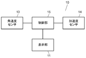
- FIG. 2 is a block diagram of the electronic device 10.
- the electronic device 10 includes a housing 12 having a display unit 11, an angular velocity sensor 13, and a control unit 15.
- the angular velocity sensor 13 detects an angular velocity around the X axis parallel to the display unit 11.
- the control unit 15 performs the first process or the second process based on the output of the angular velocity sensor 13. Specifically, when the angular velocity sensor 13 detects the positive angular velocity 16 and then detects the negative angular velocity 17, the control unit 15 performs the first process.
- the control unit 15 performs the second process.
- the positive angular velocity 16 is a clockwise direction as viewed from the user having the electronic device 10
- the negative angular velocity 17 is a counterclockwise direction as viewed from the user having the electronic device 10.
- control unit 15 performs different processing depending on the generation order of the positive angular velocity (positive angular velocity 16) and the negative angular velocity (negative angular velocity 17) generated when the casing 12 is rotated. It can be performed. Therefore, in a use environment where acceleration and angular velocity due to vibration exist, the user can operate with one hand with high accuracy.
- the electronic device 10 has an acceleration sensor 14 that detects acceleration in the Y-axis direction.
- the control unit 15 performs the first process when the acceleration sensor 14 detects the positive acceleration in the Y axis and the angular velocity sensor 13 detects the negative angular velocity after detecting the positive angular velocity, and performs the first process.
- the second process is performed when the positive angular velocity is detected after the angular velocity sensor 13 detects the negative angular velocity after 14 detects the negative acceleration of the Y axis.
- the electronic device 10 include a mobile phone, an electronic book, a tablet terminal, and the like, such as a portable electronic device that browses an electronic book (hereinafter referred to as a book), displays an image, plays music (music), or a movie. Is mentioned.
- the first process is a process of turning the page of the book
- the second process is a process of returning the page of the book.
- the first process may be a process of displaying the next book
- the second process may be a process of displaying the previous book.
- the first process is a process of displaying the next image after the image being displayed.
- the process 2 is a process for displaying an image before the currently displayed image.
- the first process is a process of displaying the image of the right part that is not displayed, and the second process is the process of the left part that is not displayed. It may be a process of displaying an image.
- the first process is a process of reproducing the next song or movie
- the second process is a previous song or movie. This is a process of playing a video.
- the first process may be a fast-forwarding process
- the second process may be a rewinding process.
- contents such as electronic books, images, and music are stored in a storage unit (not shown) connected to the control unit 15.
- the data may be stored in an external storage device connected to the storage unit 15 by wire or wireless, or via the Internet via these.
- both the angular velocity sensor 13 and the acceleration sensor 14 can output angular velocities and accelerations around the respective axes corresponding to the X axis, the Y axis, and the Z axis in FIG.
- Such sensors are disclosed in, for example, Japanese Patent Application Laid-Open Nos. 2010-230346 and 11-352143.
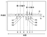
- 3A and 3B are diagrams showing measurement results using the angular velocity sensor 13 and the acceleration sensor 14.
- the output of the angular velocity sensor 13 and the output of the acceleration sensor 14 for each axis corresponding to the X axis, the Y axis, and the Z axis in FIG. 1 are shown.
- FIG. 3A the horizontal axis is time, and the vertical axis is angular velocity. Time is progressing from right to left.
- FIG. 3A shows changes in the angular velocity 18 around the X axis, the angular velocity 19 around the Y axis, and the angular velocity 20 around the Z axis.
- the user holds the casing 12 on the right hand so that the display unit 11 faces upward (the positive direction of the Z axis), and rotates it in the positive direction (clockwise) with respect to the X axis. Then, it is rotated in the negative direction (counterclockwise) to return to the original position.
- the “first operation” is performed three times at times t1, t2, and t3, and FIG. 3A shows waveforms 18A, 18B, and 18C, respectively.
- the “second operation” the user holds the casing 12 on the right hand so that the display unit 11 faces upward (the positive direction of the Z axis), and rotates it in the negative direction (counterclockwise) with respect to the X axis. Then, rotate it in the positive direction (clockwise) to return it to its original position.
- the “second operation” is performed three times at times t4, t5, and t6, and FIG. 3A shows waveforms 18D, 18E, and 18F, respectively.
- first operation first, a positive angular velocity is detected, and then a negative angular velocity is detected.
- second operation a negative angular velocity is detected first, and then a positive angular velocity is detected. This is because when the user operates the electronic device 10 having the display unit 11, the display unit 11 is always returned to the top again in order to view a book or the like.
- the first process can be performed when an angular velocity in the positive direction is detected
- the second process can be performed when an angular velocity in the negative direction is detected.
- the control unit 15 erroneously recognizes the angular velocity due to walking or vibration of the train, and the first There is a possibility that the process or the second process is executed.
- the control unit 15 determines that the “first operation” is intentionally performed by the user, and performs the first process. I do. Further, when the angular velocity sensor 13 detects a positive angular velocity after detecting a negative angular velocity, it is determined that the “second operation” has been intentionally performed by the user, and the second process is performed. By such determination, it is possible to prevent malfunction due to angular velocity due to walking or train vibration, and the user can operate the electronic device 10 with one hand with high accuracy.
- a predetermined threshold value for the angular velocity may be provided in the control unit 15.
- the control unit 15 determines that the angular velocity has been detected, so that the influence of the angular velocity due to walking or train vibration can be further reduced.
- FIG. 3B the horizontal axis is time, and the vertical axis is acceleration.
- the time progresses from right to left as in FIG. 3A.
- FIG. 3B shows changes in acceleration 21 in the X-axis direction, acceleration 22 in the Y-axis direction, and acceleration 23 in the Z-axis direction. Note that FIG. 3A and FIG. 3B have the same time on the horizontal axis.
- waveforms 22A, 22B, and 22C showing acceleration in the positive direction appear at times t1, t2, and t3 when the “first operation” is performed.
- waveforms 22D, 22E, and 22F showing acceleration in the negative direction appear at times t4, t5, and t6 at which the “second operation” is performed.
- the electronic device 10 can select an operation with higher accuracy by using such a feature of human operation. Specifically, when the acceleration sensor 14 detects the acceleration in the positive direction of the Y axis and the angular velocity sensor 13 detects the negative angular velocity after detecting the positive angular velocity, the control unit 15 detects the negative angular velocity. It is determined that the “first operation” is intentionally performed, and the first process is performed. Further, when the acceleration sensor 14 detects the negative acceleration in the Y-axis and the angular velocity sensor 13 detects the negative angular velocity and then detects the positive angular velocity, the user intentionally sets “second operation”. "Is performed, and the second process is performed.
- the electronic device 10 can further prevent malfunction and select an operation with high accuracy.
- FIG. 4 shows a process flow when the control unit 15 performs the first process or the second process based on the angular velocity sensor 13.
- control is started.
- the angular velocity sensor 13 detects a positive or negative angular velocity around the X axis. If a positive or negative angular velocity around the X axis is not detected, the process returns to the start point SP to detect the angular velocity again.
- step S2 If a positive angular velocity is detected in step S2, the process proceeds to step S3, and the control unit 15 determines whether a negative angular velocity around the X axis is detected within a predetermined time. If a negative angular velocity around the X axis is detected within a predetermined time, the process proceeds to step S4, the control unit 15 executes the first process, and the process returns to the start point SP. If a negative angular velocity around the X axis is not detected within a predetermined time, the process returns to the start point SP as it is.
- step S2 If a negative angular velocity is detected in step S2, the process proceeds to step S5, and the control unit 15 determines whether a positive angular velocity around the X axis is detected within a predetermined time. If a positive angular velocity around the X axis is detected within a predetermined time, the process proceeds to step S6, the control unit 15 executes a second process, and the process returns to the start point SP. If a positive angular velocity around the X axis is not detected within a predetermined time, the process returns to the start point SP as it is.
- FIG. 5 shows a processing flow when the control unit 15 performs the first process or the second process based on the angular velocity sensor 13 and the acceleration sensor 14.
- step S10 control is started.
- step S11 the acceleration sensor 14 detects positive or negative acceleration. If no acceleration is detected, the process returns to the start point SP in order to detect the acceleration again.
- step S11 If a positive acceleration is detected in step S11, the process proceeds to step S12, and the control unit 15 determines whether the angular velocity sensor 13 detects a positive angular velocity around the X axis. If a positive angular velocity around the X axis is not detected, the process returns to the start point SP, and if it is detected, the process proceeds to step S13.
- step S13 the control unit 15 determines whether or not a negative angular velocity around the X axis is detected within a predetermined time. If a negative angular velocity is detected within a predetermined time, the process proceeds to step S14, the first process is executed, and the process returns to the start point SP. If a negative angular velocity is not detected within a predetermined time, the process returns to the start point SP as it is.
- step S11 If a negative acceleration is detected in step S11, the process proceeds to step S15, and the control unit 15 determines whether a negative angular velocity around the X axis is detected. If a negative angular velocity around the X axis is not detected, the process returns to the start point SP, and if it is detected, the process proceeds to step S16.
- step S16 the control unit 15 determines whether or not a positive angular velocity around the X axis is detected within a predetermined time. If a positive angular velocity is detected within the predetermined time, the process proceeds to step S17, executes a second process, and returns to the start point SP. If a positive angular velocity is not detected within a predetermined time, the process returns to the start point SP as it is.
- the user completes a series of operations from rotating the electronic device 10 in the positive or negative direction to rotating it in the opposite direction and returning it to the original position.
- An appropriate time is set.
- the predetermined time is set to 0.1 seconds or more, it is possible to prevent malfunction due to disturbance such as an impact not intended by the user.
- the predetermined time within 2 seconds, the first “first operation” and the second “first operation” can be distinguished.
- the first “second operation” and the second “second operation” can be distinguished.
- predetermined time in step S3 in FIG. 4 may be different from the predetermined time in step S5.
- predetermined time in step S13 of FIG. 5 may be different from the predetermined time in step S16.
- the predetermined time in FIGS. 4 and 5 may be settable by the user. Thereby, each user can adjust individually the time interval by which "1st operation
- the operation in which the user rotates the electronic device 10 in the lateral direction is described as “first operation” or “second operation”. did.
- the operation of rotating the electronic device 10 in the vertical direction is referred to as “first operation” or “second operation”, and the first process or the second process is performed. You may control to do.
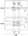
- FIG. 6A shows the angular velocity and acceleration when the “first operation” and the “second operation” are performed by holding the housing 12 with the right hand as in FIGS. 3A and 3B.
- FIG. 6B shows angular velocities and accelerations when the “first operation” and the “second operation” are performed with the housing 12 held with the left hand.
- the waveform of the acceleration 23 in the Z-axis direction differs depending on whether it is held with the right hand or the left hand.
- the acceleration 23 in the Z-axis direction in the “first motion” only slightly decreases, but in the “second motion”, the acceleration 23 in the Z-axis direction is It has greatly decreased.
- the acceleration 23 in the Z-axis direction in the “first motion” greatly decreases in the negative direction, but in the “second motion”, the acceleration 23 in the Z-axis direction. Only slightly decreases in the negative direction.
- the amount of rotation differs depending on whether the user holds the housing 12 and turns it outside the body or turns it inside. Therefore, it is considered that the waveform of the acceleration 23 in the Z-axis direction is as described above.
- the Z-axis direction of the electronic device 10 and the direction of gravity coincide. Therefore, the gravitational acceleration is maximized.
- the angle formed between the Z-axis direction of the electronic device 10 and the direction of gravity increases as it is rotated around the X-axis from this state. For this reason, the acceleration in the Z-axis direction detected by the acceleration sensor 14 decreases.
- the arm structure is used.
- the amount of rotation is reduced.
- the case of holding with the right hand corresponds to the “first operation”
- the case of holding with the left hand corresponds to the “second operation”. Therefore, the angle formed between the Z-axis direction and the gravity direction of the electronic device 10 becomes small, and the acceleration 23 in the Z-axis direction only decreases slightly.
- the amount of rotation is larger than when the user rotates the body 12 to the outside of the body.
- the control unit 15 determines whether the user has operated with the right hand or the left hand. It becomes possible.
- the control unit 15 can detect the “first operation” or the “second operation” using the angular velocity 18 around the X axis and the acceleration 22 around the X axis in the Y axis direction. Moreover, when the “first motion” is detected, the control unit 15 can determine that the operation is performed with the left hand when the change in the acceleration 23 in the Z-axis direction falls below a predetermined threshold. On the other hand, when it does not fall below the predetermined threshold value, that is, when it is equal to or higher than the predetermined threshold value, the control unit 15 can determine that the operation is with the right hand.
- the control unit 15 can determine that the operation is performed with the right hand when the acceleration 23 in the Z-axis direction falls below a predetermined threshold. On the other hand, when it does not fall below the predetermined threshold, that is, when it is equal to or higher than the predetermined threshold, the control unit 15 can determine that the operation is performed with the left hand.
- the operation of the game can be made different by determining whether the operation is performed with the right hand or the left hand. For example, in the case of a game of baseball or golf, it is possible to determine the user's dominant hand by an operation with the right hand or an operation with the left hand, and to perform a batting operation or a pitching operation according to the user's dominant hand.
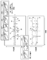
- FIG. 7 shows a comparison experiment result between the case where the casing 12 is held in the right hand and the case is returned too much in the “first operation” and the “second operation”. Note that the basic configuration of the electronic apparatus 10 in the present embodiment is the same as the configuration described in the first embodiment with reference to FIGS.
- the user rotates the electronic device 10 clockwise as shown in S25 from the start position shown in S24, and further performs an operation of returning to the original as shown in S26.
- operation which returns to the original again as shown to S28 is performed after that.
- the angular velocity 18 around the X axis shows waveforms 24 to 28, respectively.
- the user rotates the electronic device 10 in the counterclockwise direction as shown in S30 from the start position shown in S29, and further performs the returning operation as shown in S31.
- the angular velocity 18 around the X axis shows waveforms 29 to 31, respectively.
- the acceleration 23 in the Z-axis direction it is possible to discriminate between the case of returning too much in the “first operation” and the “second operation”.
- the waveform 32 of the acceleration 23 in the Z-axis direction due to the “first motion” shows only a slight decrease
- the waveform 33 due to the “second motion” shows a large decrease. ing. This is thought to be because the amount of rotation differs between when the user intentionally turns the housing 12 and when the user unintentionally turns it back.
- the control unit 15 determines that the “first-order” is not changed when the change in the acceleration 23 in the Z-axis direction does not fall below a predetermined threshold. It can be determined that the return is too much in “operation 1”, and the second process can be prevented from being performed.
- the control unit 15 does not detect the negative angular velocity after the angular velocity sensor 13 detects the positive angular velocity.
- the process immediately before detecting the negative angular velocity is prioritized.
- the process immediately before the positive angular velocity is detected is performed with priority over the second process.
- the control unit 15 detects the negative angular velocity 17 after the angular velocity sensor 13 detects the positive angular velocity 16, and the acceleration sensor 14 changes the acceleration 23 in the Z-axis direction.
- the first process is performed.
- the second process is performed when the angular velocity sensor 13 detects the negative angular velocity 17 and then detects the positive angular velocity 16 and when the acceleration sensor 14 detects a change in the acceleration 23 in the Z-axis direction.
- the “first operation” and the “second operation” can be reliably detected.
- a positive value is output in the case of a positive angular velocity
- a negative value is output in the case of a negative angular velocity.
- a positive value may be output in the case of a negative angular velocity.
- a negative value is output in the case of negative acceleration
- a negative value is output in the case of negative acceleration.
- a positive value may be output in the case of negative acceleration, and a positive value may be output in the case of negative acceleration.
- FIG. 8A is a plan view of an electronic device according to Embodiment 4 of the present invention.
- FIG. 8B is a block diagram of the electronic device shown in FIG. 8A.
- the electronic device 40 includes strain sensors 50R and 50L provided on the left and right side surfaces of the housing 12 in addition to the configuration of the electronic device 10 shown in FIGS.
- the outputs of the strain sensors 50R and 50L are also input to the control unit 15 in the same manner as the outputs of the angular velocity sensor 13 and the acceleration sensor 14.
- the other basic configuration is the same as that of the electronic device 10.
- the strain sensors 50 ⁇ / b> R and 50 ⁇ / b> L are provided at positions where the user receives pressure such as a finger when the user holds the electronic device 40.
- the control unit 15 detects the distortion and, for example, performs a plurality of pages in the page turning process as the first process. You can proceed at once.
- the control unit 15 detects the distortion and, for example, performs a plurality of page return processes in the second process. You can return pages at once.
- a plurality of contents can be sent or returned at once. Further, the feed amount and the return amount may be increased or decreased depending on the magnitude of distortion. If only this process is performed, the acceleration sensor 14 may be omitted.
- the control unit 15 can determine that the electronic device 40 is held in the user's hand. In this state, it is preferable that the control unit 15 performs the first process or the second process when receiving an output based on the angular velocity around the X axis from the angular velocity sensor 13. By such control, it is possible to prevent the first processing and the second processing from being performed wastefully even when the electronic device 40 is in a bag and the power is on.
- the strain in the strain sensors 50R and 50L changes. That is, since the effect of gravity acceleration due to the rotation is larger on the lower side than the side on which the effect of gravity acceleration is higher, the distortion becomes smaller on the upper side due to the rotation, and the distortion becomes larger on the lower side.
- the control unit 15 controls. By such control, it is possible to reliably detect the rotation operation by the user.
- control unit 15 may determine the rotation direction according to whether the difference value is positive or negative. In this case, the angular velocity sensor 13 may not be provided, but the control unit 15 can more reliably determine the rotation direction by using both.
- the strain sensors 50R and 50L can detect a relatively small strain that is caused by pressure from a finger.
- the pressure from the finger is several tens g / cm 2 .
- Such a strain sensor is disclosed in, for example, Japanese Patent Application Laid-Open No. 2007-085993.
- the strain sensors 50R and 50L are provided so as to protrude from the housing 12, but may be provided so as to be flush with the side surface of the housing 12. Furthermore, if the finger pressure is transmitted to the strain sensors 50R and 50L via the side surface of the housing 12, the housing 12 may cover the strain sensors 50R and 50L. For example, all or part of the housing 12 may be made of a deformable material.
- one strain sensor 50R, 50L is provided on each side of the housing 12, but a plurality of strain sensors may be provided on both sides of the housing 12.
- a plurality of strain sensors are used in this way, the strain distribution can be detected.
- the control unit 15 can determine which hand the user is holding the electronic device 40 with. For this reason, the same effect as Embodiment 2 can be produced.
- each of the strain sensors 50R and 50L may be one.
- the electronic device according to the present invention can be operated with high accuracy with one hand in an environment where acceleration or angular velocity due to vibration exists, so that the electronic device performs book browsing, image display, music or video playback, etc. Useful as.
- Display unit 12 Housing 13 Angular velocity sensor 14 Acceleration sensor 15 Control unit 16 Positive angular velocity 17 Negative angular velocity 18 Angular velocity 18A, 18B, 18C, 18D, 18E, 18F around X axis Waveform 19 Around Y axis Angular velocity 20 Z-axis angular velocity 21 X-axis direction acceleration 22 Y-axis direction acceleration 22A, 22B, 22C, 22D, 22E, 22F Waveform 23 Z-axis direction acceleration 24, 25, 26, 27, 28, 29, 30, 31, 32, 33 Waveform 50R, 50L Strain sensor
Landscapes
- Engineering & Computer Science (AREA)
- Theoretical Computer Science (AREA)
- General Engineering & Computer Science (AREA)
- Human Computer Interaction (AREA)
- Physics & Mathematics (AREA)
- General Physics & Mathematics (AREA)
- Computer Hardware Design (AREA)
- Microelectronics & Electronic Packaging (AREA)
- User Interface Of Digital Computer (AREA)
- Telephone Function (AREA)
Abstract
電子機器は表示部を有する筐体と、角速度センサと、加速度センサと、制御部とを有する。角速度センサは表示部と平行なX軸回りの角速度を検出する。加速度センサは表示部に垂直であって、X軸と直交するZ軸方向の加速度を検出する。制御部は、角速度センサが正の角速度を検出した後に負の角速度を検出し、かつ、加速度センサがZ軸方向の加速度の変化を検出した場合に前記第1の処理を行う。一方、角速度センサが負の角速度を検出した後に正の角速度を検出し、かつ、加速度センサがZ軸方向の加速度の変化を検出した場合に第2の処理を行う。
Description
本発明は、角速度センサを用いて電子書籍の閲覧、画像の表示、音楽又は動画の再生等を行う電子機器に関する。
図9は従来の電子機器1の外観図である。電子機器1は、右本体部2、左本体部3、右本体部2と左本体部3とを開閉可能に連結した開閉軸部4、および加速度・角速度センサ7を有する。右本体部2に設けられた右側LCD5及び左本体部3に設けられた左側LCD6は、書籍や画像等を表示する。加速度・角速度センサ7で検知された加速度又は角速度を用いて、図示しない制御部が右本体部2と左本体部3の開閉角度を検出する。また制御部は、開閉時の加速度が大きい方向を判定して、頁送り/頁戻しの処理を行う(例えば、特許文献1)。
本発明の電子機器は、表示部を有する筐体と、角速度センサと、加速度センサと、制御部とを有する。角速度センサは表示部と平行なX軸回りの角速度を検出する。加速度センサは表示部に垂直であって、X軸と直交するZ軸方向の加速度を検出する。制御部は、角速度センサが正の角速度を検出した後に負の角速度を検出し、かつ、加速度センサがZ軸方向の加速度を検出した場合に第1の処理を行う。一方、角速度センサが負の角速度を検出した後に正の角速度を検出し、かつ、加速度センサがZ軸方向の加速度を検出した場合に第2の処理を行う。
この構成により、筐体を回転させた時に発生する正の方向の角速度と負の方向の角速度の発生順序に応じて異なる処理を行うことができる。また筐体が回転したことを確実に検出して、その場合にのみ、第1の処理や第2の処理を実施することができる。そのため、振動に起因する加速度や角速度が存在する使用環境においても、片手で精度良く操作することができる。
近年、携帯電話や電子ブック、タブレット端末など、書籍の閲覧や画像の表示、音楽又は動画の再生等を行う携帯型の電子機器が増加している。このような携帯型の電子機器には、鞄を持って歩行した状態や電車の吊革につかまった状態など、振動に起因する加速度や角速度が存在する使用環境において、片手で精度良く操作ができることが求められる。
しかしながら図9に示す電子機器1は、開閉角度や加速度に基づいて頁送り/頁戻しの処理を行っている。そのため、振動に起因する加速度や角速度が存在する使用環境において、片手で精度良く操作することができない。
以下、図面を参照しながら上記課題を解決する電子機器について説明する。なお各実施の形態において、先行する実施の形態と同様の構成のものには同じ符号を付して説明し、詳細な説明を省略する場合がある。
(実施の形態1)
図1は、本発明の実施の形態1における電子機器10の説明図である。図2は電子機器10のブロック図である。電子機器10は、表示部11を有する筐体12と、角速度センサ13と、制御部15とを有する。角速度センサ13は表示部11と平行なX軸回りの角速度を検出する。制御部15は角速度センサ13の出力に基づいて第1の処理又は第2の処理を行う。具体的には、角速度センサ13が正の角速度16を検出した後に、負の角速度17を検出した場合に制御部15は第1の処理を行う。一方、角速度センサ13が負の角速度17を検出した後に、正の角速度16を検出した場合に制御部15は第2の処理を行う。正の角速度16は電子機器10を持った使用者から見て時計回りの方向、負の角速度17は電子機器10を持った使用者から見て反時計回りの方向である。
図1は、本発明の実施の形態1における電子機器10の説明図である。図2は電子機器10のブロック図である。電子機器10は、表示部11を有する筐体12と、角速度センサ13と、制御部15とを有する。角速度センサ13は表示部11と平行なX軸回りの角速度を検出する。制御部15は角速度センサ13の出力に基づいて第1の処理又は第2の処理を行う。具体的には、角速度センサ13が正の角速度16を検出した後に、負の角速度17を検出した場合に制御部15は第1の処理を行う。一方、角速度センサ13が負の角速度17を検出した後に、正の角速度16を検出した場合に制御部15は第2の処理を行う。正の角速度16は電子機器10を持った使用者から見て時計回りの方向、負の角速度17は電子機器10を持った使用者から見て反時計回りの方向である。
このように、制御部15は、筐体12を回転させた時に発生する正の方向の角速度(正の角速度16)と負の方向の角速度(負の角速度17)の発生順序に応じて異なる処理を行うことができる。そのため、振動に起因する加速度や角速度が存在する使用環境において、使用者は片手で精度良く操作することができる。
また、電子機器10は、Y軸方向の加速度を検出する加速度センサ14を有している。制御部15は、加速度センサ14がY軸の正方向の加速度を検出し、かつ、角速度センサ13が正の角速度を検出した後に負の角速度を検出した場合に第1の処理を行い、加速度センサ14がY軸の負方向の加速度を検出し、かつ、角速度センサ13が負の角速度を検出した後に正の角速度を検出した場合に第2の処理を行う。このように制御することにより、操作の精度をさらに向上させることができる。
電子機器10の具体例としては、携帯電話や電子ブック、タブレット端末など、電子書籍(以下、書籍)の閲覧や画像の表示、音楽(楽曲)又は動画の再生等を行う携帯型の電子機器などが挙げられる。
電子機器10が書籍を閲覧可能に表示する機能を有する場合には、例えば、第1の処理は書籍の頁送りを行う処理であり、第2の処理は書籍の頁戻しを行う処理である。その他、書籍の表紙を表示している場合には、第1の処理は次の書籍を表示する処理であり、第2の処理は前の書籍を表示する処理であってもよい。
電子機器10が順序の決められた複数の画像のうちの1つを表示する機能を有する場合には、例えば、第1の処理は表示中の画像の次の画像を表示する処理であり、第2の処理は表示中の画像の前の画像を表示する処理である。その他、例えば、画像の一部のみを表示している場合には、第1の処理は表示されていない右側部分の画像を表示する処理であり、第2の処理は表示されていない左側部分の画像を表示する処理であってもよい。
電子機器10が順序の決められた複数の楽曲又は動画を再生する機能を有する場合には、第1の処理は次の楽曲又は動画を再生する処理であり、第2の処理は前の楽曲又は動画を再生する処理である。その他、例えば、第1の処理は早送りを行う処理であり、第2の処理は巻き戻しを行う処理であってもよい。
なお電子書籍、画像、楽曲などのコンテンツは、制御部15に接続された図示しない記憶部に格納されている。あるいは有線または無線、またはこれらを介してインターネットで記憶部15に接続された外部記憶装置に保管されていてもよい。
以下、角速度センサ13及び加速度センサ14を用いた制御について、具体的に説明する。なおここでは角速度センサ13、加速度センサ14ともに図1のX軸、Y軸、Z軸に対応する各軸回りの角速度、加速度をそれぞれ出力可能である。このようなセンサは例えば特開2010―230346号公報や特開平11-352143号公報に開示されている。ただし、各実施の形態における用途に適合すればよいので必ずしも3軸対応型のセンサを使用する必要はない。
図3A、図3Bは角速度センサ13及び加速度センサ14を用いた測定結果を示す図である。図1のX軸、Y軸、Z軸に対応する各軸の角速度センサ13の出力及び加速度センサ14の出力が示されている。
図3Aでは横軸が時間であり、縦軸が角速度である。なお右から左に向けて時間が進行している。図3AはX軸回りの角速度18、Y軸回りの角速度19、Z軸回りの角速度20の変化を示している。
「第1の動作」で使用者は、表示部11が上(Z軸の正の方向)を向くように筐体12を右手に持ち、X軸に関して正の方向に(時計回り)に回転させ、その後に負の方向(反時計回り)に回転させて元の位置に戻す。図示するように時刻t1、t2、t3で計3回の「第1の動作」が行なわれ、図3Aはそれぞれ波形18A、18B、18Cを示している。
「第2の動作」で使用者は、表示部11が上(Z軸の正の方向)を向くように筐体12を右手に持ち、X軸に関して負の方向(反時計回り)に回転させ、その後に正の方向に(時計回り)に回転させて元の位置に戻す。図示するように時刻t4、t5、t6で計3回の「第2の動作」が行なわれ、図3Aはそれぞれ波形18D、18E、18Fを示している。
図3Aより、「第1の動作」においては、まず正の角速度が検出された後に、負の角速度が検出されている。また、「第2の動作」においては、まず負の角速度が検出された後に、正の角速度が検出されている。これは、表示部11を有する電子機器10を使用者が操作する場合、書籍等を見るために最後には必ず表示部11が再び上を向くように戻すためである。
なお、正又は負の一方向に回転させた際の角速度のみを用いて所定の処理を行うことも可能である。すなわち、正の方向の角速度を検出した場合に、第1の処理を行い、負の方向の角速度を検出した場合に第2の処理を行うことができる。しかし、鞄を持って歩行した状態や電車の吊革につかまった状態で電子機器10を使用する場合には、歩行や電車の振動に起因する角速度を制御部15が誤って認識し、第1の処理又は第2の処理を実行してしまう可能性がある。
しかし、図3Aに示すように、使用者が意図的に操作した場合には必ず表示部11を上に戻す動作を伴うため、この戻す動作を考慮して処理を実行することにより、歩行や電車に起因する誤作動を防止することができる。
すなわち、制御部15は、角速度センサ13が正の角速度を検出した後に負の角速度を検出した場合に、使用者により意図的に「第1の動作」が行われたと判断し、第1の処理を行う。また、角速度センサ13が負の角速度を検出した後に正の角速度を検出した場合に、使用者により意図的に「第2の動作」が行われたと判断し、第2の処理を行う。このような判断により、歩行や電車の振動に起因する角速度により誤作動が生じることを防止し、使用者は片手で精度良く電子機器10を操作することができる。
なお、制御部15において角速度における所定の閾値を設けてもよい。そして角速度の絶対値がこの閾値となった場合に、角速度が検出されたと制御部15が判断することにより、歩行や電車の振動に起因する角速度の影響をさらに低減することができる。
図3Bでは横軸が時間であり、縦軸が加速度である。図3Aと同容に右から左に向けて時間が進行している。図3BはX軸方向の加速度21は加速度、Y軸方向の加速度22、Z軸方向の加速度23の変化を示している。なお、図3Aと図3Bとは横軸の時間が一致している。
Y軸方向の加速度22に着目すると、「第1の動作」を行った時刻t1、t2、t3で正の方向の加速度を示す波形22A、22B、22Cが現れている。また、「第2の動作」を行った時刻t4、t5、t6で負の方向の加速度を示す波形22D、22E、22Fが現れている。
使用者が「第1の動作」を行う際には、筐体12を同一の位置に維持したまま回転動作のみを行うことは非常に困難である。そのため、使用者は筐体12をY軸の正方向に動かしてしまう。同様に、「第2の動作」を行う際には、使用者は筐体12をY軸の負方向に動かしてしまう。そのため図3Bに示すような波形が現れる。
このような人の動作の特徴を利用することにより、電子機器10はさらに精度良く動作を選択することができる。具体的には、制御部15は、加速度センサ14がY軸の正の方向の加速度を検出し、かつ、角速度センサ13が正の角速度検出した後に負の角速度を検出した場合に、使用者により意図的に「第1の動作」が行われたと判断し、第1の処理を行う。また、加速度センサ14がY軸の負方向の加速度を検出し、かつ、角速度センサ13が負の角速度を検出した後に正の角速度を検出した場合に、使用者により意図的に「第2の動作」が行われたと判断し、第2の処理を行う。このような制御により、加速度を用いて「第1の動作」と「第2の動作」とを区別するとともに、角速度による「第1の動作」と「第2の動作」とを区別することができる。そのため、電子機器10はさらに誤作動を防止し、精度良く動作を選択することができる。
図4は、制御部15が角速度センサ13に基づいて第1の処理又は第2の処理を行う場合の処理フローを示している。ステップS1では制御が開始される。ステップS2で角速度センサ13はX軸回りの正または負の角速度を検出する。X軸回りの正または負の角速度が検出されなかった場合は、再び角速度を検出するために処理はスタートポイントSPに戻る。
ステップS2で正の角速度が検出された場合には、処理はステップS3に進み、制御部15は所定時間以内にX軸回りの負の角速度が検出されるかどうかを判定する。所定時間以内にX軸回りの負の角速度が検出された場合には、処理はステップS4に進み、制御部15は第1の処理を実行し、処理はスタートポイントSPに戻る。所定時間以内にX軸回りの負の角速度が検出されない場合には処理はそのままスタートポイントSPに戻る。
ステップS2で負の角速度が検出された場合には、処理はステップS5に進み、制御部15は所定時間以内にX軸回りの正の角速度が検出されるかどうかを判定する。所定時間以内にX軸回りの正の角速度が検出された場合には、処理はステップS6に進み、制御部15は第2の処理を実行し、処理はスタートポイントSPに戻る。所定時間以内にX軸回りの正の角速度が検出されない場合には処理はそのままスタートポイントSPに戻る。
図5は、制御部15が角速度センサ13及び加速度センサ14に基づいて第1の処理又は第2の処理を行う場合の処理フローを示している。ステップS10では制御が開始される。ステップS11で加速度センサ14は正または負の加速度を検出する。加速度が検出されなかった場合は、再び加速度を検出するために処理はスタートポイントSPに戻る。
ステップS11で正の加速度が検出された場合には、処理はステップS12に進み、制御部15は角速度センサ13によってX軸回りの正の角速度が検出されるかどうかを判定する。X軸回りの正の角速度が検出されなかった場合には、処理はスタートポイントSPに戻り、検出された場合には処理はステップS13に進む。
ステップS13では、所定時間以内にX軸回りの負の角速度が検出されるかどうかを制御部15は判定する。所定時間以内に負の角速度が検出された場合には、処理はステップS14に進み、第1の処理を実行し、スタートポイントSPに戻る。所定時間以内に負の角速度が検出されない場合には処理はそのままスタートポイントSPに戻る。
ステップS11で負の加速度が検出された場合には、処理はステップS15に進み、X軸回りの負の角速度が検出されるかどうかを制御部15は判定する。X軸回りの負の角速度が検出されなかった場合には、処理はスタートポイントSPに戻り、検出された場合に処理はステップS16に進む。
ステップS16では、所定時間以内にX軸回りの正の角速度が検出されるかどうかを制御部15は判定する。所定時間以内に正の角速度が検出された場合には、処理はステップS17に進み、第2の処理を実行し、スタートポイントSPに戻る。所定時間以内に正の角速度が検出されない場合には処理はそのままスタートポイントSPに戻る。
図4、図5における所定時間には、使用者が電子機器10を正又は負の方向に回転させてから再び反対方向に回転させて元の位置に戻すまでの一連の動作を完了させるための適当な時間が設定される。好ましくは、所定時間を0.1秒以上とすることにより、使用者の意図しない衝撃等の外乱に起因する誤作動を防止することができる。また、好ましくは、所定時間を2秒以内とすることにより、1回目の「第1の動作」と2回目の「第1の動作」とを区別することができる。又は、1回目の「第2の動作」と2回目の「第2の動作」とを区別することができる。
なお、図4のステップS3における所定時間とステップS5における所定時間とを異ならせてもよい。同様に、図5のステップS13における所定時間とステップS16における所定時間とを異ならせてもよい。これにより、「第1の動作」の操作感と「第2の動作」の操作感とを異ならせることができる。
なお、図4、図5における所定時間は、使用者により設定可能であってもよい。これにより、「第1の動作」又は「第2の動作」が認識される時間間隔を各使用者が個別に調整することができる。そのため、各使用者にとって違和感のない操作を実現することができる。
なお、本実施の形態においては、使用者が電子機器10を横方向に回転させる動作(図1のX軸回りに回転させる動作)を「第1の動作」又は「第2の動作」として説明した。しかし、電子機器10を縦方向に回転させる動作(図1のY軸回りに回転させる動作)を「第1の動作」又は「第2の動作」とし、第1の処理又は第2の処理を行うように制御してもよい。
(実施の形態2)
本実施の形態において、Z軸方向の加速度を用いた制御について図1、図2および図6A、図6Bを参照しながら説明する。図6A、図6Bは、筐体12を右手で持った場合と左手で持った場合の比較実験結果である。なお本実施の形態における電子機器10の基本構成は実施の形態1で図1、図2を参照しながら説明した構成と同じである。
本実施の形態において、Z軸方向の加速度を用いた制御について図1、図2および図6A、図6Bを参照しながら説明する。図6A、図6Bは、筐体12を右手で持った場合と左手で持った場合の比較実験結果である。なお本実施の形態における電子機器10の基本構成は実施の形態1で図1、図2を参照しながら説明した構成と同じである。
図6Aは、図3A、図3Bと同様に、筐体12を右手で持って「第1の動作」及び「第2の動作」を行った場合の角速度及び加速度である。また図6Bは、筐体12を左手で持って「第1の動作」及び「第2の動作」を行った場合の角速度及び加速度である。
図6A、図6Bから分かるように、右手で持った場合であっても左手で持った場合であっても、X軸回りの角速度18の正負の発生順序や、Y軸方向の加速度22の発生方向は同じである。すなわち、X軸回りの角速度18については、持ち手にかかわらず、「第1の動作」の場合には正の角速度が検出された後に負の角速度が検出されている。「第2の動作」の場合には負の角速度が検出された後に正の角速度が検出されている。また、Y軸方向の加速度22については、持ち手にかかわらず、「第1の動作」の場合には正の方向の加速度が検出され、「第2の動作」の場合には負の方向の加速度が検出されている。
一方、Z軸方向の加速度23の波形は右手で持った場合と左手で持った場合で異なっている。右手で持った場合には、「第1の動作」の場合のZ軸方向の加速度23はわずかに減少するのみであるが、「第2の動作」の場合にはZ軸方向の加速度23は大きく減少している。一方、左手で持った場合には、「第1の動作」の場合のZ軸方向の加速度23は負方向に大きく減少するが、「第2の動作」の場合にはZ軸方向の加速度23は負方向にわずかに減少するのみである。使用者が筐体12を持って体の外側に回す場合と内側に回す場合とで回転量が異なる。そのためにZ軸方向の加速度23の波形は上述のようになると考えられる。
表示部11が上面を向いた初期状態においては、電子機器10のZ軸方向と重力方向とが一致する。そのため、重力加速度が最大となる。この状態からX軸回りに回転させるに従って、電子機器10のZ軸方向と重力方向との成す角度が大きくなる。そのため、加速度センサ14が検出するZ軸方向の加速度が減少する。
ここで、使用者が筐体12を体の外側(右手で持つ場合には「第1の動作」、左手で持つ場合には「第2の動作」)に回転させる場合には、腕の構造上、回転量が小さくなる。右手で持つ場合には「第1の動作」、左手で持つ場合には「第2の動作」に相当する。そのため、電子機器10のZ軸方向と重力方向との成す角度は小さくなり、Z軸方向の加速度23はわずかに減少するのみである。一方、使用者が筐体12を体の内側に回転させる場合には、体の外側に回転させる場合と比べて回転量が大きくなる。右手で持つ場合には「第2の動作」、左手で持つ場合には「第1の動作」に相当する。そのため、電子機器10のZ軸方向と重力方向との成す角度が大きくなり、Z軸方向の加速度23は大きく減少する。
以上のように、腕の構造に起因するZ軸方向の加速度23の変化の違いを利用し、制御部15は使用者が右手で操作を行ったのか、左手で操作を行ったのかを判別することが可能となる。
このように制御部15は、X軸回りの角速度18やX軸回りのY軸方向の加速度22を用いて「第1の動作」又は「第2の動作」を検出することができる。しかも、「第1の動作」を検出した場合、制御部15はZ軸方向の加速度23の変化が所定の閾値を下回った場合には左手による操作であると判断することができる。一方、所定の閾値を下回らない場合、すなわち所定の閾値以上の場合に制御部15は右手による操作であると判断することができる。
同様に、「第2の動作」を検出した場合、制御部15はZ軸方向の加速度23が所定の閾値を下回った場合に右手による操作であると判断することができる。一方、所定の閾値を下回らない場合、すなわち所定の閾値以上の場合に制御部15は左手による操作であると判断することができる。
特に、電子機器10がゲーム機能を有する場合には、右手による操作であるか左手による操作であるかを判別することにより、ゲームの動作を異ならせることができる。例えば、野球やゴルフのゲームである場合には、右手による操作か左手による操作かで使用者の利き手を判断し、使用者の利き手に応じたバッティング動作や投球動作とすることが可能となる。
(実施の形態3)
本実施の形態においては、Z軸方向の加速度23を用いた別の制御について図1、図2および図7を参照しながら説明する。図7は、筐体12を右手に持った状態で、「第1の動作」において戻しすぎた場合と、「第2の動作」との比較実験結果である。なお本実施の形態における電子機器10の基本構成は実施の形態1で図1、図2を参照しながら説明した構成と同じである。
本実施の形態においては、Z軸方向の加速度23を用いた別の制御について図1、図2および図7を参照しながら説明する。図7は、筐体12を右手に持った状態で、「第1の動作」において戻しすぎた場合と、「第2の動作」との比較実験結果である。なお本実施の形態における電子機器10の基本構成は実施の形態1で図1、図2を参照しながら説明した構成と同じである。
「第1の動作」で使用者は、S24に示す開始位置から、S25に示すように時計方向に電子機器10を回転し、さらにS26に示すように元に戻す操作を行う。S27に示すように戻しすぎた場合、その後にS28に示すように再度元に戻す操作を行っている。これらの動作S24~S28に対応して、X軸回りの角速度18はそれぞれ波形24~28を示す。
「第2の動作」で使用者は、S29に示す開始位置から、S30に示すように反時計方向に電子機器10を回転し、さらにS31に示すように元に戻す操作を行う。これらの動作S29~S31に対応して、X軸回りの角速度18はそれぞれ波形29~31を示す。
「第1の動作」における元に戻す操作(S26)から再度元に戻す操作(S28)までの波形と、「第2の動作」における開始位置(S29)から元に戻す操作(S31)までの波形はほぼ同一である。そのため、両者を区別することが非常に困難である。したがって、使用者が「第1の動作」を行っているにもかかわらず、制御部15は「第2の動作」であると誤認識して、第2の処理を行う可能性がある。
しかし、Z軸方向の加速度23を用いることにより、「第1の動作」において戻しすぎた場合と、「第2の動作」とを判別することが可能となる。図7から分かるように、「第1の動作」によるZ軸方向の加速度23の波形32はわずかな減少を示しているのみであるが、「第2の動作」による波形33は大きな減少を示している。これは、使用者が筐体12を意図的に回す場合と、意図せずに戻しすぎてしまう場合とで回転量が異なることが原因と考えられる。
従って、制御部15は、負の角速度が検出された後に、正の角速度が検出された場合であっても、Z軸方向の加速度23の変化が所定の閾値を下回らない場合には、「第1の動作」における戻し過ぎであると判断し、第2の処理を行わないようにすることができる。
このように、Z軸方向の加速度23の変化が所定の閾値を下回った場合に、制御部15は角速度センサ13が正の角速度を検出した後に負の角速度を検出しても、第1の処理よりも負の角速度を検出する直前の処理を優先して行う。同様に、角速度センサ13が負の角速度を検出した後に正の角速度を検出しても、第2の処理よりも正の角速度を検出する直前の処理を優先して行う。この制御により、戻し過ぎによる誤作動を防止し、さらに片手での操作を精度よく検出することが可能となる。
なお、実施の形態2、3において、制御部15は、角速度センサ13が正の角速度16を検出した後に負の角速度17を検出し、かつ、加速度センサ14がZ軸方向の加速度23の変化を検出した場合に第1の処理を行う。また角速度センサ13が負の角速度17を検出した後に正の角速度16を検出し、かつ、加速度センサ14がZ軸方向の加速度23の変化を検出した場合に第2の処理を行う。このように角速度センサ13の出力に加え、加速度センサ14の出力を制御に用いることにより、「第1の動作」および「第2の動作」を確実に検出することができる。
なお、実施の形態1~3で説明した図3A、図6A、図6B、図7において、正の角速度の場合に正の値が出力され、負の角速度の場合に負の値が出力されている。しかし、角速度センサ13の出力信号の極性は適宜設定されるものであるため、正の角速度の場合に負の値が出力され、負の角速度の場合に正の値が出力されてもよい。同様に、図3B、図6A、図6B、図7において正の加速度の場合に正の値が出力され、負の加速度の場合に負の値が出力されている。しかしながら、加速度センサ14の出力信号の極性は適宜設定されるものであるため、正の加速度の場合に負の値が出力され、負の加速度の場合に正の値が出力されてもよい。
(実施の形態4)
図8Aは本発明の実施の形態4における電子機器の平面図である。図8Bは図8Aに示す電子機器のブロック図である。
図8Aは本発明の実施の形態4における電子機器の平面図である。図8Bは図8Aに示す電子機器のブロック図である。
電子機器40は図1、図2に示す電子機器10の構成に加え、筐体12の左右側面に設けられた歪センサ50R、50Lを有する。歪センサ50R、50Lの出力も、角速度センサ13、加速度センサ14の出力と同様に制御部15に入力される。これ以外の基本的な構成は電子機器10と同様である。
歪センサ50R、50Lは使用者が電子機器40を持つときに指等の圧力を受ける位置に設けられている。使用者が「第1の動作」をする際に歪センサ50Rを押して歪を与えると、制御部15はこの歪を検出して、例えば第1の処理である頁送りの処理において複数の頁を一度に進めることができる。一方、使用者が「第2の動作」をする際に歪センサ50Lを押して歪を与えると、制御部15はこの歪を検出して、例えば第2の処理である頁戻しの処理において複数の頁を一度に戻すことができる。あるいは画像、楽曲、動画などのコンテンツの選択の際に、複数のコンテンツを一度に送ったり、戻したりすることができる。また歪の大きさによってその送り量、戻し量を増減させてもよい。なおこの処理だけであれば、加速度センサ14はなくても実施可能である。
また、電子機器10が、電源が入っている状態で鞄等に入っていて加速度または角速度が加わった場合に、誤って第1の処理または第2の処理が行われてしまう虞がある。これに対し、使用者が手で電子機器40を保持している場合、歪センサ50R、50Lにはそれぞれ圧力が印加されて基準となる値の歪が発生している。したがって歪センサ50R、50Lからの上記基準値に相当する以上の出力がある場合に、制御部15は電子機器40が使用者の手に保持されていると判断することができる。この状態で角速度センサ13からX軸回りの角速度に基づく出力を受けた時に制御部15は第1の処理または第2の処理を実施することが好ましい。このような制御により、鞄などに電子機器40が入っていて電源が入っていても無駄に第1の処理や第2の処理を実施することを防止することができる。
さらに、使用者が電子機器40をX軸の回りに回転させると、歪センサ50R、50Lにおける歪が変化する。すなわち、回転によって重力加速度による影響が上になる側に比べて下になる側で大きくなるので、回転によって上になる側では歪が小さくなり、下になる側では歪が大きくなる。たとえば、反時計周りに回転させると歪センサ50Lの出力が大きくなり歪センサ50Rの出力が小さくなる。そこで、それぞれの歪センサの基準値からの変化の差(差分値)を計算し、その差分値の差の絶対値が所定の閾値以上の場合に第1の処理、第2の処理を実施するように制御部15が制御することが好ましい。このような制御により、使用者による回転動作を確実に検出することができる。
また、上記差分値の差が正か負かによって制御部15が回転方向を判断してもよい。この場合、角速度センサ13がなくともよいが、両者を併用することによって制御部15は回転方向をより確実に判断することができる。
なお歪センサ50R、50Lは指からの圧力によって生じる程度の比較的小さい歪を検出することができる。指からの圧力は数10g/cm2である。このような歪センサは例えば特開2007-085993号公報に開示されている。
また図8Aにおいて歪センサ50R、50Lは筐体12から突出するように設けられているが、筐体12の側面と同一平面になるように設けられていてもよい。さらに筐体12の側面を介して指の圧力が歪センサ50R、50Lに伝わるのであれば、歪センサ50R、50Lを筐体12が覆っていてもよい。例えば筐体12の全部または一部が変形可能な材料で構成されていればよい。
また図8Aにおいて歪センサ50R、50Lは筐体12の両側面にそれぞれ1つ設けられているが、複数個の歪センサを筐体12の両側面に設けてもよい。このように複数の歪センサを用いると、歪の分布を検出することができる。使用者が電子機器40を手で保持する場合、筐体12の幅が掌に対しある程度の大きさがあれば、筐体12の側面の一方には親指が当たり、他方には人差し指、中指、薬指、小指のうち2本以上が当たる。その結果、親指の当たった側面では歪が集中し、他方の側面では歪が二箇所以上に分布する。このようなそれぞれの側面での歪の分布を検出することによって、使用者がどちらの手で電子機器40を保持しているのか、制御部15が判断することができる。このため、実施の形態2と同様の効果を奏することができる。なお歪の分布を検出することができる歪センサを用いる場合には、歪センサ50R、50Lはそれぞれ1つでもよい。
本発明の電子機器は、振動に起因する加速度や角速度が存在する使用環境において、片手で精度良く操作することができるので、書籍の閲覧、画像の表示、音楽又は動画の再生等を行う電子機器として有用である。
10,40 電子機器
11 表示部
12 筐体
13 角速度センサ
14 加速度センサ
15 制御部
16 正の角速度
17 負の角速度
18 X軸回りの角速度
18A,18B,18C,18D,18E,18F 波形
19 Y軸回りの角速度
20 Z軸回りの角速度
21 X軸方向の加速度
22 Y軸方向の加速度
22A,22B,22C,22D,22E,22F 波形
23 Z軸方向の加速度
24,25,26,27,28,29,30,31,32,33 波形
50R,50L 歪センサ
11 表示部
12 筐体
13 角速度センサ
14 加速度センサ
15 制御部
16 正の角速度
17 負の角速度
18 X軸回りの角速度
18A,18B,18C,18D,18E,18F 波形
19 Y軸回りの角速度
20 Z軸回りの角速度
21 X軸方向の加速度
22 Y軸方向の加速度
22A,22B,22C,22D,22E,22F 波形
23 Z軸方向の加速度
24,25,26,27,28,29,30,31,32,33 波形
50R,50L 歪センサ
Claims (8)
- 表示部を有する筐体と、
前記表示部と平行なX軸回りの角速度を検出する角速度センサと、
前記表示部に垂直であって、X軸と直交するZ軸方向の加速度を検出する加速度センサと、
前記角速度センサと前記加速度センサとの出力に基づいて第1の処理又は第2の処理を行う制御部と、
を備え、
前記制御部は、
前記角速度センサが正の角速度を検出した後に負の角速度を検出し、かつ、前記加速度センサがZ軸方向の加速度の変化を検出した場合に前記第1の処理を行い、
前記角速度センサが負の角速度を検出した後に正の角速度を検出し、かつ、前記加速度センサがZ軸方向の加速度の変化を検出した場合に前記第2の処理を行う、
電子機器。 - 前記加速度センサはさらに、前記表示部と平行であって、X軸と直交するY軸方向の加速度を検出し、
前記制御部は、
前記加速度センサがY軸の正方向の加速度を検出し、かつ、前記角速度センサが正の角速度を検出した後に負の角速度を検出し、かつ、前記加速度センサがZ軸方向の加速度の変化を検出した場合に前記第1の処理を行い、
前記加速度センサがY軸の負方向の加速度を検出し、かつ、前記角速度センサが負の角速度を検出した後に正の角速度を検出し、かつ、前記加速度センサがZ軸方向の加速度の変化を検出した場合に前記第2の処理を行う、
請求項1記載の電子機器。 - 前記制御部は、
前記加速度センサが検出したZ軸方向の加速度の変化が所定の閾値を下回った場合に、
前記角速度センサが正の角速度を検出した後に負の角速度を検出しても前記第1の処理よりも、前記負の角速度を検出する直前の処理を優先して行い、
前記角速度センサが負の角速度を検出した後に正の角速度を検出しても前記第2の処理よりも、前記正の角速度を検出する直前の処理を優先して行う、
請求項1記載の電子機器。 - 前記制御部は、
前記筐体をX軸に関して正の方向に回転させ、その後に負の方向に回転させる動作における、前記加速度センサが検出したZ軸方向の加速度の変化が、所定の閾値以上の場合に左手による操作であると判定し、前記所定の閾値を下回る場合に右手による操作であると判定する、
請求項1記載の電子機器。 - 前記制御部は、
前記筐体をX軸に関して負の方向に回転させ、その後に正の方向に回転させる動作における、前記加速度センサが検出したZ軸方向の加速度の変化が、所定の閾値以上の場合に右手による操作であると判定し、前記所定の閾値を下回る場合に左手による操作であると判定する、
請求項1記載の電子機器。 - 前記電子機器は電子書籍を閲覧可能に表示する機能を有し、前記第1の処理は前記電子書籍の頁送りを行う処理であり、前記第2の処理は前記電子書籍の頁戻しを行う処理である、
請求項1記載の電子機器。 - 前記電子機器は順序の決められた複数の画像のうちの1つを表示する機能を有し、前記第1の処理は表示中の画像の次の画像を表示する処理であり、前記第2の処理は表示中の画像の前の画像を表示する処理である、
請求項1記載の電子機器。 - 前記電子機器は順序の決められた複数の楽曲又は動画を再生する機能を有し、前記第1の処理は次の楽曲又は動画を再生する処理であり、前記第2の処理は前の楽曲又は動画を再生する処理である、
請求項1記載の電子機器。
Priority Applications (3)
| Application Number | Priority Date | Filing Date | Title |
|---|---|---|---|
| EP12776224.3A EP2703948A4 (en) | 2011-04-27 | 2012-04-26 | ELECTRONIC DEVICE |
| US14/005,535 US20140009392A1 (en) | 2011-04-27 | 2012-04-26 | Electronic device |
| CN201280020054.3A CN103502909A (zh) | 2011-04-27 | 2012-04-26 | 电子设备 |
Applications Claiming Priority (4)
| Application Number | Priority Date | Filing Date | Title |
|---|---|---|---|
| JP2011099186A JP5045835B1 (ja) | 2011-04-27 | 2011-04-27 | 電子機器 |
| JP2011-099186 | 2011-04-27 | ||
| JP2012-098438 | 2012-04-24 | ||
| JP2012098438A JP2013228771A (ja) | 2012-04-24 | 2012-04-24 | 電子機器 |
Publications (1)
| Publication Number | Publication Date |
|---|---|
| WO2012147349A1 true WO2012147349A1 (ja) | 2012-11-01 |
Family
ID=47071879
Family Applications (1)
| Application Number | Title | Priority Date | Filing Date |
|---|---|---|---|
| PCT/JP2012/002852 Ceased WO2012147349A1 (ja) | 2011-04-27 | 2012-04-26 | 電子機器 |
Country Status (4)
| Country | Link |
|---|---|
| US (1) | US20140009392A1 (ja) |
| EP (1) | EP2703948A4 (ja) |
| CN (1) | CN103502909A (ja) |
| WO (1) | WO2012147349A1 (ja) |
Cited By (5)
| Publication number | Priority date | Publication date | Assignee | Title |
|---|---|---|---|---|
| CN104252243A (zh) * | 2013-06-27 | 2014-12-31 | 南京迈瑞生物医疗电子有限公司 | 一种手势操控医疗设备及其手势操控方法 |
| JP2016180616A (ja) * | 2015-03-23 | 2016-10-13 | ラピスセミコンダクタ株式会社 | 半導体装置、携帯端末装置および運動検出方法 |
| JP2017506392A (ja) * | 2014-02-21 | 2017-03-02 | クアルコム,インコーポレイテッド | 空中超音波ペンジェスチャー |
| JP2017507413A (ja) * | 2014-01-31 | 2017-03-16 | クアルコム,インコーポレイテッド | デバイス上のローリングジェスチャーを特定するための技法 |
| JP2017199309A (ja) * | 2016-04-28 | 2017-11-02 | シャープ株式会社 | 情報処理装置、携帯端末、機能実行方法および機能実行制御プログラム |
Families Citing this family (7)
| Publication number | Priority date | Publication date | Assignee | Title |
|---|---|---|---|---|
| CN104375752A (zh) * | 2014-11-06 | 2015-02-25 | 惠州Tcl移动通信有限公司 | 基于移动终端的电子书翻页控制方法、系统及移动终端 |
| CN104318909B (zh) * | 2014-11-12 | 2017-02-22 | 京东方科技集团股份有限公司 | 移位寄存器单元、栅极驱动电路及其驱动方法、显示面板 |
| CN104407705B (zh) * | 2014-11-27 | 2017-10-20 | 上海斐讯数据通信技术有限公司 | 隔空手势操作图片的方法及电子终端 |
| CN105652825A (zh) * | 2015-04-29 | 2016-06-08 | 宇龙计算机通信科技(深圳)有限公司 | 一种控制指令获取方法及装置 |
| JP2017102429A (ja) * | 2015-11-19 | 2017-06-08 | パナソニック インテレクチュアル プロパティ コーポレーション オブ アメリカPanasonic Intellectual Property Corporation of America | ウェアラブル端末および制御方法 |
| CN107037965A (zh) * | 2016-02-04 | 2017-08-11 | 北京搜狗科技发展有限公司 | 一种基于输入的信息展示方法、装置和移动终端 |
| CN107544686B (zh) * | 2016-06-28 | 2021-01-05 | 北京小米移动软件有限公司 | 操作执行方法及装置 |
Citations (8)
| Publication number | Priority date | Publication date | Assignee | Title |
|---|---|---|---|---|
| JPH064208A (ja) * | 1992-06-19 | 1994-01-14 | Sharp Corp | 情報処理装置 |
| JPH11352143A (ja) | 1998-04-06 | 1999-12-24 | Matsushita Electric Ind Co Ltd | 加速度センサ |
| JP2003216300A (ja) * | 2002-01-17 | 2003-07-31 | Seiko Epson Corp | 表示装置、表示装置の制御方法、プログラムおよび記録媒体 |
| JP2006323859A (ja) * | 1995-06-19 | 2006-11-30 | Matsushita Electric Ind Co Ltd | 書類表示装置 |
| JP2007085993A (ja) | 2005-09-26 | 2007-04-05 | Matsushita Electric Ind Co Ltd | 歪センサとその製造方法 |
| JP2007304988A (ja) * | 2006-05-12 | 2007-11-22 | Seiko Epson Corp | モーションコマンド処理システム |
| JP2009217415A (ja) | 2008-03-10 | 2009-09-24 | Sanyo Electric Co Ltd | 表示装置 |
| JP2010230346A (ja) | 2009-03-26 | 2010-10-14 | Panasonic Corp | 角速度センサ |
Family Cites Families (8)
| Publication number | Priority date | Publication date | Assignee | Title |
|---|---|---|---|---|
| US20050212760A1 (en) * | 2004-03-23 | 2005-09-29 | Marvit David L | Gesture based user interface supporting preexisting symbols |
| US7880737B2 (en) * | 2005-03-22 | 2011-02-01 | Vijayvardhan Elchuri | Graphical method and system for making drawings directly in three-dimensions on a computer monitor or other display device |
| JP4582116B2 (ja) * | 2007-06-06 | 2010-11-17 | ソニー株式会社 | 入力装置、制御装置、制御システム、制御方法及びそのプログラム |
| US20090307633A1 (en) * | 2008-06-06 | 2009-12-10 | Apple Inc. | Acceleration navigation of media device displays |
| US8587515B2 (en) * | 2008-08-05 | 2013-11-19 | Apple Inc. | Systems and methods for processing motion sensor generated data |
| US8881204B2 (en) * | 2008-09-04 | 2014-11-04 | Core Wireless Licensing, S.a.r.l. | Method for providing access to media content through a server |
| US8368658B2 (en) * | 2008-12-02 | 2013-02-05 | At&T Mobility Ii Llc | Automatic soft key adaptation with left-right hand edge sensing |
| US8542186B2 (en) * | 2009-05-22 | 2013-09-24 | Motorola Mobility Llc | Mobile device with user interaction capability and method of operating same |
-
2012
- 2012-04-26 CN CN201280020054.3A patent/CN103502909A/zh active Pending
- 2012-04-26 EP EP12776224.3A patent/EP2703948A4/en not_active Withdrawn
- 2012-04-26 US US14/005,535 patent/US20140009392A1/en not_active Abandoned
- 2012-04-26 WO PCT/JP2012/002852 patent/WO2012147349A1/ja not_active Ceased
Patent Citations (8)
| Publication number | Priority date | Publication date | Assignee | Title |
|---|---|---|---|---|
| JPH064208A (ja) * | 1992-06-19 | 1994-01-14 | Sharp Corp | 情報処理装置 |
| JP2006323859A (ja) * | 1995-06-19 | 2006-11-30 | Matsushita Electric Ind Co Ltd | 書類表示装置 |
| JPH11352143A (ja) | 1998-04-06 | 1999-12-24 | Matsushita Electric Ind Co Ltd | 加速度センサ |
| JP2003216300A (ja) * | 2002-01-17 | 2003-07-31 | Seiko Epson Corp | 表示装置、表示装置の制御方法、プログラムおよび記録媒体 |
| JP2007085993A (ja) | 2005-09-26 | 2007-04-05 | Matsushita Electric Ind Co Ltd | 歪センサとその製造方法 |
| JP2007304988A (ja) * | 2006-05-12 | 2007-11-22 | Seiko Epson Corp | モーションコマンド処理システム |
| JP2009217415A (ja) | 2008-03-10 | 2009-09-24 | Sanyo Electric Co Ltd | 表示装置 |
| JP2010230346A (ja) | 2009-03-26 | 2010-10-14 | Panasonic Corp | 角速度センサ |
Non-Patent Citations (1)
| Title |
|---|
| See also references of EP2703948A4 |
Cited By (8)
| Publication number | Priority date | Publication date | Assignee | Title |
|---|---|---|---|---|
| CN104252243A (zh) * | 2013-06-27 | 2014-12-31 | 南京迈瑞生物医疗电子有限公司 | 一种手势操控医疗设备及其手势操控方法 |
| JP2017507413A (ja) * | 2014-01-31 | 2017-03-16 | クアルコム,インコーポレイテッド | デバイス上のローリングジェスチャーを特定するための技法 |
| JP2017507412A (ja) * | 2014-01-31 | 2017-03-16 | クアルコム,インコーポレイテッド | デバイスにユーザ入力を供給するための技法 |
| US10423245B2 (en) | 2014-01-31 | 2019-09-24 | Qualcomm Incorporated | Techniques for providing user input to a device |
| US10775901B2 (en) | 2014-01-31 | 2020-09-15 | Qualcomm Incorporated | Techniques for identifying rolling gestures on a device |
| JP2017506392A (ja) * | 2014-02-21 | 2017-03-02 | クアルコム,インコーポレイテッド | 空中超音波ペンジェスチャー |
| JP2016180616A (ja) * | 2015-03-23 | 2016-10-13 | ラピスセミコンダクタ株式会社 | 半導体装置、携帯端末装置および運動検出方法 |
| JP2017199309A (ja) * | 2016-04-28 | 2017-11-02 | シャープ株式会社 | 情報処理装置、携帯端末、機能実行方法および機能実行制御プログラム |
Also Published As
| Publication number | Publication date |
|---|---|
| EP2703948A4 (en) | 2014-12-17 |
| CN103502909A (zh) | 2014-01-08 |
| US20140009392A1 (en) | 2014-01-09 |
| EP2703948A1 (en) | 2014-03-05 |
Similar Documents
| Publication | Publication Date | Title |
|---|---|---|
| EP2703948A1 (en) | Electronic device | |
| US9823736B2 (en) | Systems and methods for processing motion sensor generated data | |
| CN102265242B (zh) | 在移动设备上使用运动处理来控制和访问内容 | |
| US9207781B2 (en) | Input apparatus, control system, handheld apparatus, and calibration method | |
| US20090262074A1 (en) | Controlling and accessing content using motion processing on mobile devices | |
| US20170329419A1 (en) | Combining gyromouse input and touch input for navigation in an augmented and/or virtual reality environment | |
| US20140043277A1 (en) | Apparatus and associated methods | |
| JP2004246875A (ja) | 電気器具および電気器具のユーザインターフェースに入力を供給するための方法 | |
| US20080147217A1 (en) | Motion responsive portable media player | |
| WO2011028325A2 (en) | Processing motion sensor data using accessible templates | |
| KR101340794B1 (ko) | 휴대용 단말기 및 그의 구동 방법 | |
| CN101840277B (zh) | 输入装置、控制装置、控制系统和控制方法 | |
| EP1818768A2 (en) | Display controller with a motion sensor on a portable electronic device | |
| JP2013228771A (ja) | 電子機器 | |
| US8294676B2 (en) | Touch control electronic device and operating method thereof | |
| JP2010152587A (ja) | 入力装置、制御システム、ハンドヘルド装置及び校正方法 | |
| JP5045835B1 (ja) | 電子機器 | |
| CN102667937B (zh) | 多媒体装置及控制多媒体装置的操作的方法 | |
| US20170351346A1 (en) | Controlling an item on a screen | |
| TWI700615B (zh) | 藉由敲擊控制電子裝置的方法和敲擊控制組 | |
| JP5187780B2 (ja) | 可搬型電子機器、可搬型電子機器の重心制御方法および重心制御プログラム | |
| CN102135548B (zh) | 可侦测运动方向的可携式电子装置及其使用的侦测方法 | |
| KR101514018B1 (ko) | 센서를 이용한 재생 제어 장치 및 그 보조장치 | |
| CN106371598A (zh) | 一种基于可穿戴设备的启动搜题方法和系统 | |
| JP2014052845A (ja) | ポータブルメディアプレーヤー |
Legal Events
| Date | Code | Title | Description |
|---|---|---|---|
| 121 | Ep: the epo has been informed by wipo that ep was designated in this application |
Ref document number: 12776224 Country of ref document: EP Kind code of ref document: A1 |
|
| WWE | Wipo information: entry into national phase |
Ref document number: 14005535 Country of ref document: US |
|
| NENP | Non-entry into the national phase |
Ref country code: DE |