WO2012147488A1 - マルチアングル測色計 - Google Patents
マルチアングル測色計 Download PDFInfo
- Publication number
- WO2012147488A1 WO2012147488A1 PCT/JP2012/059364 JP2012059364W WO2012147488A1 WO 2012147488 A1 WO2012147488 A1 WO 2012147488A1 JP 2012059364 W JP2012059364 W JP 2012059364W WO 2012147488 A1 WO2012147488 A1 WO 2012147488A1
- Authority
- WO
- WIPO (PCT)
- Prior art keywords
- light
- unit
- photoelectric conversion
- illumination
- detection unit
- Prior art date
- Legal status (The legal status is an assumption and is not a legal conclusion. Google has not performed a legal analysis and makes no representation as to the accuracy of the status listed.)
- Ceased
Links
Images








Classifications
-
- G—PHYSICS
- G01—MEASURING; TESTING
- G01J—MEASUREMENT OF INTENSITY, VELOCITY, SPECTRAL CONTENT, POLARISATION, PHASE OR PULSE CHARACTERISTICS OF INFRARED, VISIBLE OR ULTRAVIOLET LIGHT; COLORIMETRY; RADIATION PYROMETRY
- G01J3/00—Spectrometry; Spectrophotometry; Monochromators; Measuring colours
- G01J3/46—Measurement of colour; Colour measuring devices, e.g. colorimeters
- G01J3/50—Measurement of colour; Colour measuring devices, e.g. colorimeters using electric radiation detectors
-
- G—PHYSICS
- G01—MEASURING; TESTING
- G01J—MEASUREMENT OF INTENSITY, VELOCITY, SPECTRAL CONTENT, POLARISATION, PHASE OR PULSE CHARACTERISTICS OF INFRARED, VISIBLE OR ULTRAVIOLET LIGHT; COLORIMETRY; RADIATION PYROMETRY
- G01J3/00—Spectrometry; Spectrophotometry; Monochromators; Measuring colours
- G01J3/02—Details
- G01J3/0205—Optical elements not provided otherwise, e.g. optical manifolds, diffusers, windows
- G01J3/0218—Optical elements not provided otherwise, e.g. optical manifolds, diffusers, windows using optical fibers
-
- G—PHYSICS
- G01—MEASURING; TESTING
- G01J—MEASUREMENT OF INTENSITY, VELOCITY, SPECTRAL CONTENT, POLARISATION, PHASE OR PULSE CHARACTERISTICS OF INFRARED, VISIBLE OR ULTRAVIOLET LIGHT; COLORIMETRY; RADIATION PYROMETRY
- G01J3/00—Spectrometry; Spectrophotometry; Monochromators; Measuring colours
- G01J3/02—Details
- G01J3/0272—Handheld
-
- G—PHYSICS
- G01—MEASURING; TESTING
- G01J—MEASUREMENT OF INTENSITY, VELOCITY, SPECTRAL CONTENT, POLARISATION, PHASE OR PULSE CHARACTERISTICS OF INFRARED, VISIBLE OR ULTRAVIOLET LIGHT; COLORIMETRY; RADIATION PYROMETRY
- G01J3/00—Spectrometry; Spectrophotometry; Monochromators; Measuring colours
- G01J3/02—Details
- G01J3/08—Beam switching arrangements
-
- G—PHYSICS
- G01—MEASURING; TESTING
- G01J—MEASUREMENT OF INTENSITY, VELOCITY, SPECTRAL CONTENT, POLARISATION, PHASE OR PULSE CHARACTERISTICS OF INFRARED, VISIBLE OR ULTRAVIOLET LIGHT; COLORIMETRY; RADIATION PYROMETRY
- G01J3/00—Spectrometry; Spectrophotometry; Monochromators; Measuring colours
- G01J3/02—Details
- G01J3/10—Arrangements of light sources specially adapted for spectrometry or colorimetry
-
- G—PHYSICS
- G01—MEASURING; TESTING
- G01J—MEASUREMENT OF INTENSITY, VELOCITY, SPECTRAL CONTENT, POLARISATION, PHASE OR PULSE CHARACTERISTICS OF INFRARED, VISIBLE OR ULTRAVIOLET LIGHT; COLORIMETRY; RADIATION PYROMETRY
- G01J3/00—Spectrometry; Spectrophotometry; Monochromators; Measuring colours
- G01J3/12—Generating the spectrum; Monochromators
- G01J3/18—Generating the spectrum; Monochromators using diffraction elements, e.g. grating
-
- G—PHYSICS
- G01—MEASURING; TESTING
- G01J—MEASUREMENT OF INTENSITY, VELOCITY, SPECTRAL CONTENT, POLARISATION, PHASE OR PULSE CHARACTERISTICS OF INFRARED, VISIBLE OR ULTRAVIOLET LIGHT; COLORIMETRY; RADIATION PYROMETRY
- G01J3/00—Spectrometry; Spectrophotometry; Monochromators; Measuring colours
- G01J3/28—Investigating the spectrum
-
- G—PHYSICS
- G01—MEASURING; TESTING
- G01J—MEASUREMENT OF INTENSITY, VELOCITY, SPECTRAL CONTENT, POLARISATION, PHASE OR PULSE CHARACTERISTICS OF INFRARED, VISIBLE OR ULTRAVIOLET LIGHT; COLORIMETRY; RADIATION PYROMETRY
- G01J3/00—Spectrometry; Spectrophotometry; Monochromators; Measuring colours
- G01J3/28—Investigating the spectrum
- G01J3/30—Measuring the intensity of spectral lines directly on the spectrum itself
- G01J3/36—Investigating two or more bands of a spectrum by separate detectors
-
- G—PHYSICS
- G01—MEASURING; TESTING
- G01J—MEASUREMENT OF INTENSITY, VELOCITY, SPECTRAL CONTENT, POLARISATION, PHASE OR PULSE CHARACTERISTICS OF INFRARED, VISIBLE OR ULTRAVIOLET LIGHT; COLORIMETRY; RADIATION PYROMETRY
- G01J3/00—Spectrometry; Spectrophotometry; Monochromators; Measuring colours
- G01J3/46—Measurement of colour; Colour measuring devices, e.g. colorimeters
- G01J3/50—Measurement of colour; Colour measuring devices, e.g. colorimeters using electric radiation detectors
- G01J3/502—Measurement of colour; Colour measuring devices, e.g. colorimeters using electric radiation detectors using a dispersive element, e.g. grating, prism
-
- G—PHYSICS
- G01—MEASURING; TESTING
- G01J—MEASUREMENT OF INTENSITY, VELOCITY, SPECTRAL CONTENT, POLARISATION, PHASE OR PULSE CHARACTERISTICS OF INFRARED, VISIBLE OR ULTRAVIOLET LIGHT; COLORIMETRY; RADIATION PYROMETRY
- G01J3/00—Spectrometry; Spectrophotometry; Monochromators; Measuring colours
- G01J3/46—Measurement of colour; Colour measuring devices, e.g. colorimeters
- G01J3/50—Measurement of colour; Colour measuring devices, e.g. colorimeters using electric radiation detectors
- G01J3/504—Goniometric colour measurements, for example measurements of metallic or flake based paints
-
- G—PHYSICS
- G01—MEASURING; TESTING
- G01N—INVESTIGATING OR ANALYSING MATERIALS BY DETERMINING THEIR CHEMICAL OR PHYSICAL PROPERTIES
- G01N21/00—Investigating or analysing materials by the use of optical means, i.e. using sub-millimetre waves, infrared, visible or ultraviolet light
- G01N21/17—Systems in which incident light is modified in accordance with the properties of the material investigated
- G01N21/25—Colour; Spectral properties, i.e. comparison of effect of material on the light at two or more different wavelengths or wavelength bands
- G01N21/251—Colorimeters; Construction thereof
-
- G—PHYSICS
- G01—MEASURING; TESTING
- G01N—INVESTIGATING OR ANALYSING MATERIALS BY DETERMINING THEIR CHEMICAL OR PHYSICAL PROPERTIES
- G01N21/00—Investigating or analysing materials by the use of optical means, i.e. using sub-millimetre waves, infrared, visible or ultraviolet light
- G01N21/17—Systems in which incident light is modified in accordance with the properties of the material investigated
- G01N21/25—Colour; Spectral properties, i.e. comparison of effect of material on the light at two or more different wavelengths or wavelength bands
- G01N21/255—Details, e.g. use of specially adapted sources, lighting or optical systems
-
- G—PHYSICS
- G01—MEASURING; TESTING
- G01N—INVESTIGATING OR ANALYSING MATERIALS BY DETERMINING THEIR CHEMICAL OR PHYSICAL PROPERTIES
- G01N21/00—Investigating or analysing materials by the use of optical means, i.e. using sub-millimetre waves, infrared, visible or ultraviolet light
- G01N21/17—Systems in which incident light is modified in accordance with the properties of the material investigated
- G01N21/47—Scattering, i.e. diffuse reflection
- G01N2021/4704—Angular selective
- G01N2021/4711—Multiangle measurement
-
- G—PHYSICS
- G01—MEASURING; TESTING
- G01N—INVESTIGATING OR ANALYSING MATERIALS BY DETERMINING THEIR CHEMICAL OR PHYSICAL PROPERTIES
- G01N21/00—Investigating or analysing materials by the use of optical means, i.e. using sub-millimetre waves, infrared, visible or ultraviolet light
- G01N21/17—Systems in which incident light is modified in accordance with the properties of the material investigated
- G01N21/47—Scattering, i.e. diffuse reflection
- G01N2021/4735—Solid samples, e.g. paper, glass
-
- G—PHYSICS
- G01—MEASURING; TESTING
- G01N—INVESTIGATING OR ANALYSING MATERIALS BY DETERMINING THEIR CHEMICAL OR PHYSICAL PROPERTIES
- G01N21/00—Investigating or analysing materials by the use of optical means, i.e. using sub-millimetre waves, infrared, visible or ultraviolet light
- G01N21/17—Systems in which incident light is modified in accordance with the properties of the material investigated
- G01N21/55—Specular reflectivity
- G01N21/57—Measuring gloss
- G01N2021/575—Photogoniometering
-
- G—PHYSICS
- G01—MEASURING; TESTING
- G01N—INVESTIGATING OR ANALYSING MATERIALS BY DETERMINING THEIR CHEMICAL OR PHYSICAL PROPERTIES
- G01N2201/00—Features of devices classified in G01N21/00
- G01N2201/02—Mechanical
- G01N2201/022—Casings
- G01N2201/0221—Portable; cableless; compact; hand-held
-
- G—PHYSICS
- G01—MEASURING; TESTING
- G01N—INVESTIGATING OR ANALYSING MATERIALS BY DETERMINING THEIR CHEMICAL OR PHYSICAL PROPERTIES
- G01N2201/00—Features of devices classified in G01N21/00
- G01N2201/06—Illumination; Optics
- G01N2201/061—Sources
-
- G—PHYSICS
- G01—MEASURING; TESTING
- G01N—INVESTIGATING OR ANALYSING MATERIALS BY DETERMINING THEIR CHEMICAL OR PHYSICAL PROPERTIES
- G01N2201/00—Features of devices classified in G01N21/00
- G01N2201/08—Optical fibres; light guides
Definitions
- the present invention relates to a multi-angle colorimeter, and more particularly, to an optical arrangement improving technique for correcting an attitude error of the colorimeter with respect to a measurement surface.
- Metallic paint and pearl color paint used for automobile paintings, etc. may appear to vary in color depending on the direction of the observer due to the effect of the internal glittering material, so the paint evaluation (evaluation of paint color) A multi-angle colorimeter that illuminates or receives light at multiple angles is used.
- metallic coating and pearl color coating used for automobile coating and the like include flake-like aluminum pieces and mica pieces called luster materials in the coating film, exhibiting so-called metallic effect and pearl effect. This is because the contribution of the glitter material to the reflection characteristics varies depending on the illumination and observation direction.
- the sample surface of the object to be measured is illuminated from a plurality of directions and received from one direction (multidirectional illumination one-way light reception), or A multi-angle colorimeter having a multi-angle geometry (optical arrangement) that illuminates the sample surface of the object to be measured from one direction and receives light from a plurality of directions (one-way illumination multi-directional light reception) is used.
- the object to be measured is a sample having a curvature such as a bumper of an automobile
- a posture error in which the sample normal does not coincide with the reference axis of the colorimeter during measurement.
- the angle direction close to the specularly reflected light has a large angle dependency of the reflection characteristics, so the influence of this error cannot be ignored.
- the optical base unit incorporating the measurement optical system is held by an elastic body such as a spring with respect to the housing, and the sample and the housing
- a technique has been proposed for reducing measurement errors by keeping the illumination / light-receiving geometry constant regardless of the contact angle.
- Patent Document 1 aims to reduce the posture error by devising the mechanism, but requires a complicated mechanical structure in terms of structure in which the internal mechanism is held by an elastic body. Becomes large. Moreover, since the internal mechanism is a structure that moves, there is a concern that reliability and durability are poor when used under severe conditions such as when a measurement target is moving in an automobile production line.
- the above-mentioned known technique has a drawback that it is necessary for the measurer to manually adjust the posture, and it takes time and effort to start the measurement.
- Patent Document 2 eliminates the disadvantages of the technique of Patent Document 1 and the above-described known technique, two sets of components of the light receiving system such as the sensor and the peripheral circuit system are required purely. There are concerns about the complexity and cost increase of the equipment.
- the present invention has been made in view of such circumstances, and prevents an increase in the number of constituent elements by simply arranging a plurality of optical systems having the same configuration with respect to the occurrence of errors due to posture errors.
- An object of the present invention is to provide a multi-angle colorimeter capable of correcting an attitude error while achieving downsizing and cost reduction of the apparatus.
- a multi-angle colorimeter is (a) arranged on a virtual reference plane including a predetermined reference line, and emits light at different angles toward a predetermined measurement point defined on the reference line.
- a plurality of first illumination units that perform irradiation; and (b) on the reference plane, arranged symmetrically with each of the plurality of first illumination units with respect to the reference line, and irradiated with light toward the predetermined measurement point.
- a plurality of second illuminating units and (c) a light detecting unit, arranged on the reference plane, each facing the measurement point and symmetrically arranged with respect to the reference line And a second light receiving window, and a single photodetecting unit provided with a photoelectric conversion element that receives the first and second lights received by the first and second light receiving windows, respectively, and converts them into electrical signals And (d) based on the signal, A calculation unit that obtains detection values of the first and second lights and obtains color information of the measurement surface existing at the measurement point based on the detection values;
- a multi-angle colorimeter is (a) arranged on a virtual reference plane including a predetermined reference line, and at different angles toward a predetermined measurement point defined on the reference line.
- a first photodetecting unit including first and second light receiving windows, a first photoelectric conversion element that receives the first light received by the first light receiving window and converts the first light into an electrical signal; Receives the second light received by the second light receiving window and converts it into an electrical signal
- a second light detection unit including a second photoelectric conversion element, and (d) a detection value of the first light and the second light based on the signal, and the detection
- a light detection unit having a wavelength resolution lower than that of the first light detection unit as the second light detection unit. Unit is used.
- a multi-angle colorimeter is (a) arranged on a virtual reference plane including a predetermined reference line, and has a predetermined distance toward a predetermined measurement point defined on the reference line.
- a first illumination unit that irradiates light at an angle; and
- a second illumination that is arranged symmetrically with the first illumination unit with respect to the reference line on the reference plane and that irradiates light toward the measurement point.
- a photodetecting unit that is arranged symmetrically with respect to the reference line on the reference plane, and each pair includes a plurality of pairs of photoelectric conversion elements facing the measurement point, and (d) the plurality An arithmetic unit that obtains color information of a measurement surface existing at the measurement point based on a detection value obtained from a photoelectric conversion signal from each of a pair of photoelectric conversion elements, the first illumination unit and the second The illumination unit shares a light source.
- the appropriate color measurement is performed even if the reference line is inclined in the reference plane from the normal line of the sample surface. be able to.
- a configuration in which the first and second light received by the first and second light receiving windows are detected by a single light detection unit a configuration in which the light sources of the first illumination unit and the second illumination unit are shared, By adopting, for example, a configuration using a light detection unit having a wavelength resolution lower than that of the first light detection unit as the second light detection unit, downsizing and cost reduction can be achieved.
- the internal components can be shared by using a single light detection unit in common, it is not necessary to consider individual differences between detection units that occur when using a plurality of light detection units. Further, by sharing the light source, it is not necessary to consider individual differences between the light sources that occur when a plurality of light sources are used.
- FIG. 1A is a perspective view showing an appearance of a multi-angle colorimeter according to an embodiment of the present invention
- FIG. 1B is a schematic diagram for explaining an angular relationship between a central axis of a measuring instrument main body and a measurement surface of a measurement sample.
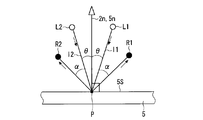
- FIG. 2 is a diagram showing the positional relationship between the optical system and the measurement surface.
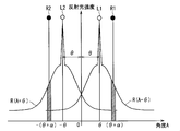
- FIG. 3 is a graph showing the reflected light intensity.
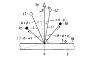
- FIG. 4 is a diagram showing the positional relationship between the optical system and the measurement surface.
- FIG. 5 is a graph showing the reflected light intensity.
- FIG. 6 is a diagram illustrating a functional configuration example of the multi-angle colorimeter according to the first embodiment.
- FIG. 7 is a diagram illustrating the light detection unit.
- FIG. 1A is a perspective view showing an appearance of a multi-angle colorimeter according to an embodiment of the present invention
- FIG. 1B is a schematic diagram for explaining an angular relationship between a central axis of
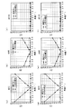
- FIG. 8 is a graph showing actually measured values based on experiments in which posture error correction processing using symmetrical arrangement is performed.
- FIG. 9 is a diagram illustrating a functional configuration example of a multi-angle colorimeter according to a first modification of the first embodiment.
- FIG. 10 is a diagram illustrating a functional configuration example of a multi-angle colorimeter according to a second modification of the first embodiment.
- FIG. 11 is a flowchart showing an operation flow of the multi-angle colorimeter according to the first embodiment.
- FIG. 12 is a flowchart showing an operation flow of the multi-angle colorimeter according to the first embodiment.
- FIG. 13 is a diagram illustrating a functional configuration example of the multi-angle colorimeter according to the second embodiment.
- FIG. 14 is a graph showing actual measurement values based on experiments in which posture error correction processing using symmetrical arrangement is performed.
- FIG. 15 is a flowchart showing an operation flow of the multi-angle colorimeter according to the second embodiment.
- FIG. 16 is a diagram illustrating a functional configuration example of a multi-angle colorimeter according to the third embodiment.
- FIG. 17 is a flowchart showing an operation flow of the multi-angle colorimeter according to the third embodiment.
- FIG. 18 is a diagram illustrating a functional configuration example of a multi-angle colorimeter according to the fourth embodiment.
- FIG. 19 is a flowchart showing an operation flow of the multi-angle colorimeter according to the fourth embodiment.
- FIG. 1 is a perspective view showing an external appearance common to the multi-angle colorimeter according to each embodiment of the present invention, and a schematic diagram for explaining the positional relationship between the measuring instrument main body and the measurement surface of the object to be measured.
- FIG. 1A is a perspective view showing the appearance of a multi-angle colorimeter.
- the multi-angle colorimeter 100 (100A to 100E) has a box shape in which components described later (see FIGS. 7, 9, 10, 13, 16, and 18) are accommodated.
- the measuring instrument main body 2 includes a measurement opening 3 drilled in the bottom wall and an operation display panel 4 which is disposed at a suitable surface and includes a display showing the measurement results, an operation switch, and the like, and is portable. Configures a portable colorimeter.
- FIG. 1B is a schematic diagram for explaining the angle between the central axis of the measuring instrument main body of the multi-angle colorimeter and the measurement surface of the measurement sample.
- the measurement opening 3 of the multi-angle colorimeter 100 (100A to 100E) is measured toward the object to be measured 5, and the object to be measured 5 facing the measurement opening 3 is measured.
- the area becomes the measurement area 5a.
- the measuring instrument main body 2 is placed on the surface of the object to be measured 5 so that the central axis 2n of the measuring instrument main body 2 (normal line of the measurement opening 3) and the normal line 5n of the measuring area 5a coincide. Arrange to face each other.
- the object to be measured 5 is a curved surface such as a bumper of an automobile, it is difficult to accurately match the center axis 2n of the measuring device body 2 with the normal 5n of the measurement surface. 2n often does not coincide with the normal of the measurement surface, and is inclined with respect to the normal of the measurement surface.
- an inclined environment such a measurement environment is referred to as an “inclined environment”.
- Each embodiment to be described later is a multi-angle colorimeter in which a plurality of light receiving elements are arranged corresponding to one illumination element, and a symmetrical arrangement method in which those sets are combined in an axial symmetry.
- the advantage of the multi-angle colorimeter is that the reflected light detection function is achieved by receiving the reflected light obtained by reflecting light from one illumination element at different angles. Is to increase.
- the advantages of the symmetrical arrangement method are as follows. However, for the purpose of paying attention to the symmetrical arrangement method, a simple model in which one illumination and one light receiving method is paired symmetrically is used. The following situation is the same in the multi-angle system.
- FIG. 2 to FIG. 5 are diagrams for explaining a situation caused by a deviation in angle between the central axis of the measuring instrument main body and the measurement surface of the measurement object.
- the angle is defined as positive from the normal line 5n to the right side of the drawing sheet, and the angle from the normal line 5n to the left side of the drawing sheet is defined as minus.
- FIG. 2 is a diagram showing the positional relationship between the optical system and the measurement surface when the central axis 2n of the measuring instrument main body 2 and the normal line 5n of the measurement surface 5s coincide with each other.
- the illumination light l1 is irradiated from the illumination system L1 in the direction inclined by the angle + ⁇ from the normal line 5n
- the illumination light l1 is reflected at the measurement point P on the measurement surface 5s
- Light is received by the light receiving system R1 in the direction inclined by the angle + ( ⁇ + ⁇ ) from the line 5n or the light receiving system R2 in the direction inclined by the angle ⁇ ( ⁇ + ⁇ ) from the normal line 5n.
- the illumination light l2 when the illumination light l2 is irradiated from the illumination system L2 in the direction inclined by the angle ⁇ from the normal 5n, the illumination light l2 is also reflected at the measurement point P on the measurement surface 5s and is received by the light receiving system. Light is received by R1 or light receiving system R2.
- FIG. 3 is a graph showing the reflected light intensity when the optical system and the measurement surface are in the positional relationship of FIG.
- the vertical axis represents the reflected light intensity
- the horizontal axis represents the angle A with respect to the normal 5n.
- the specularly reflected light with respect to the illumination lights 11 and 12 from the illumination systems L1 and L2 is emitted in a direction that is axially symmetric with respect to the illumination light with respect to the normal 5n.
- the specularly reflected light with respect to the illumination light 11 is emitted in the direction of ⁇ where the illumination system L2 is positioned
- the regular reflected light with respect to the illumination light 12 is emitted in the direction of + ⁇ where the illumination system L1 is positioned.
- the reflected light is generated not only at the center peak position of the regular reflected light but also at other angles.
- (I) has a sharp peak in the angle of specular reflection light
- (Ii) It can be approximated by a Gaussian function having attenuation characteristics symmetrically at the angles on both sides that are in a symmetrical positional relationship with respect to the peak angle of the regular reflection light
- (Iii) The diffused light can be approximated by a cosine function with the normal 5n of the measurement surface 5s as a peak. Note that the ratio of the component (ii) is large at an angle relatively close to the regular reflection light, and the ratio of the component (iii) is large at an angle relatively far from the regular reflection light.
- the reflected light intensity with respect to the illumination light l1 from the illumination system L1 can be approximated to the reflection characteristic R (A + ⁇ ), and the reflected light intensity with respect to the illumination light l2 from the illumination system L2 is the reflection characteristic.
- FIG. 4 is a diagram showing the positional relationship between the optical system and the measurement surface when the central axis 2n of the measuring instrument body 2 is inclined in the angle ⁇ direction with respect to the normal 5n of the measurement surface 5s. is there.
- the position of the illumination system L1 is changed from the angle + ( ⁇ ) to the angle + with respect to the normal 5n.
- the position of the illumination system L2 is tilted from the angle ⁇ ( ⁇ ) to the angle ⁇ ( ⁇ + ⁇ ) with respect to the normal 5n, and the position of the light receiving system R1 is tilted with respect to the normal 5n.
- the angle of ( ⁇ + ⁇ ) is inclined to angle + ( ⁇ + ⁇ )
- the position of the light receiving system R2 is inclined from angle ⁇ ( ⁇ + ⁇ ) to angle ⁇ ( ⁇ + ⁇ + ⁇ ) with respect to the normal 5n.
- FIG. 5 is a graph showing the reflected light intensity when the optical system and the measurement surface are irradiated with light in the positional relationship of FIG.
- the reflected light intensity with respect to the illumination light l1 from the illumination system L1 can be approximated to the reflection characteristic R (A + ( ⁇ )), and the illumination light l2 from the illumination system L2 Can be approximated to the reflection characteristic R (A ⁇ ( ⁇ + ⁇ )).
- the reflected light intensity at the angle + ( ⁇ + ⁇ ) of the light receiving system R1 is R ( ⁇ 2 ⁇ )
- the reflected light intensity at the angle ⁇ ( ⁇ + ⁇ + ⁇ ) of the light receiving system R2 is R ( ⁇ 2 ⁇ ). Therefore, the area indicated by the oblique lines indicating these light amounts has a relationship of R ( ⁇ 2 ⁇ ) ⁇ R ( ⁇ 2 ⁇ ).
- the measurement information of only the light receiving system R1 (or the light receiving system R2) is used as the measurement point P.
- the color information of the existing measurement surface cannot be obtained correctly.
- the central axis 2n and the normal line 5n do not coincide with each other, if the information of the reflected light is acquired independently with the symmetrical optical arrangement as in the light receiving systems R1 and R2, all the information is obtained as described above. Since the amount of received light can be regarded as substantially equal if the inclination of the measuring instrument is relatively small, this attitude error can be reduced by a correction process that performs averaging.
- a multi-angle illumination unidirectional light-receiving type multi-angle colorimeter requires two sets of components of the light receiving system such as sensors and peripheral circuit systems.
- the unidirectional illumination multidirectional light receiving type multi-angle colorimeter there arises a problem that two sets of each component of the illumination system are required.
- a multi-angle colorimeter of a multi-directional illumination unidirectional light receiving type uses a common light receiving system.
- the multi-angle colorimeter of the directional illumination multi-directional light receiving type by making the illumination system common, the number of parts is reduced and the size is reduced, and the influence of variation in the characteristics of each part is also reduced. Accurately measure the color of the measuring surface.
- FIG. 6 is a diagram showing a basic functional configuration of the multi-angle illumination unidirectional light-receiving type multi-angle colorimeter 100 according to the first embodiment of the present invention, in which only optical fibers are arranged in an axial symmetry, This is an example in which a light detection unit (polychromator) is shared, and FIG. 7 is a diagram schematically illustrating the internal configuration of the light detection unit.
- the multi-angle colorimeter 100 includes a light detection unit 40 and a control unit 70.
- the light detection unit 40 is arranged on a virtual reference plane including a predetermined reference line (the central axis 2n of the measuring device main body 2), and emits light at different angles toward a predetermined measurement point P defined on the reference line.
- the light detection unit 40 includes a single light detection unit 41 and an element group for introducing light into the light detection unit 41.
- the optical fiber 42 is bifurcated, and the lower end surfaces of these branches are first and second light receiving windows 5A and 5B arranged symmetrically with respect to the central axis 2n.
- a minute lens for efficiently condensing the reflected light from the measurement surface onto the light receiving windows 5A and 5B is arranged.
- the first and second light receiving windows 5A and 5B are arranged on the reference plane, and each face the measurement point P.
- the expression “light receiving window” does not specify a particular structure by itself, but may include all configurations that allow incident light reflected from the measurement surface.
- Each branch of the optical fiber 42 is close and parallel in the upper part, and the upper end thereof is arranged toward the entrance slit 50 of the light detection unit 41. However, the light from each branch of the optical fiber 42 is not mixed. Therefore, the light passing through each branch of the optical fiber 42 enters the light detection unit 41 in a state of being spatially distinguished from each other.
- the light detection unit 41 receives the first and second light beams g1 and g2 received by the first and second light receiving windows 5A and 5B, respectively, through the optical fiber 42 and optical path components such as an optical diffraction element described later.
- the photoelectric conversion element 52 that converts the spectral components of these lights g1 and g2 into electrical signals is provided.
- control unit 70 detection values of the first and second lights g1 and g2 are obtained based on the electric signal, and color information of the measurement surface existing at the measurement point P is obtained based on the detection values.
- a calculation unit 72 is provided.
- an operation display panel 4 a measurement switch 65, a display unit 66, a memory unit 60, and a measurement control unit 71 are provided.
- the reference plane When the central axis 2n is perpendicular to the measurement plane, the reference plane includes the central axis 2n and is a plane perpendicular to the measurement plane.
- this surface is referred to as a “main geometry surface”.
- a virtual plane perpendicular to the reference plane (main geometry plane) is called a “sub-geometry plane”.
- the multi-angle colorimeter of the present invention employs a symmetrical arrangement for illumination and light reception, which is the inclination of the measurement surface in a direction parallel to the main geometry surface.
- Each of the first illuminating units 1A to 4A and the second illuminating units 1B to 4B includes, for example, a light source composed of a xenon flash lamp, a restricting plate that restricts light from the light source, and a collimator lens (not shown). ).
- Light emitting circuits 11A to 14A and 11B to 14B that emit light from the light source are provided in the vicinity of the first illumination units 1A to 4A and the second illumination units 1B to 4B, respectively.
- the first illuminating units 1A to 4A and the second illuminating units 1B to 4B are arranged in axisymmetric positions with respect to the central axis 2n, and are based on two main standards in the evaluation methods of metallic coating and pearl color coating.
- each combination of the first illumination unit 2A and the second illumination unit 2B, the first illumination unit 3A and the second illumination unit 3B, and the first illumination unit 4A and the second illumination unit 4B is a central axis. It is arranged at a position symmetrical to 2n.
- the illumination unit 4A (4B) arranged on the central axis 2n serves as both the first illumination unit 4A and the second illumination unit 4B.
- the light emitting circuits 11A to 14A and 11B to 14B are, for example, a main capacitor for applying a DC high voltage of several hundred volts to the electrode of the light source, a charging circuit for charging the main capacitor, and being wound in close contact with the light source.
- a trigger generating circuit for applying an AC high voltage of several tens of thousands of volts to a trigger electrode made of a metal wire, and further, for example, a semiconductor switch element made of IGBT, and a drive voltage applied to the semiconductor switch element Drive circuit.
- a high DC voltage is applied to both electrodes of the light source by the main capacitor, and an alternating high voltage is instantaneously applied to the trigger electrode via the trigger transformer by the trigger capacitor of the trigger generation circuit.
- the light source is triggered and a direct current flows from the main capacitor to emit light. Thereafter, the light emission can be stopped by turning off the semiconductor switch at a desired timing.
- the restricting plate is arranged so that the opening of the restricting plate coincides with the focal point of the collimating lens, and the light beam from the light source that has passed through the opening of the restricting plate is collimated by the collimating lens to become a parallel beam.
- the measurement point P of the object 5 is illuminated.
- the light detection unit 40 includes first and second light receiving windows 5A and 5B for converging parallel rays from the measurement point P of the object to be measured 5, and imaging positions of the first and second light receiving windows 5A and 5B.
- first and second light receiving windows 5A and 5B for converging parallel rays from the measurement point P of the object to be measured 5, and imaging positions of the first and second light receiving windows 5A and 5B.
- optical fibers 42-1 and 42-2 are provided with optical fibers 42-1 and 42-2, and the incident light is guided to the single light detection unit 41 through the optical fibers 42-1 and 42-2. Then, the light detection unit 41 separates the incident light beam for each wavelength and outputs spectral data corresponding to the light intensity.
- the single light detection unit 41 includes a concave diffraction grating 51 and two line sensors (one-dimensional photoelectric conversion elements) 52-1 and 52-2. As shown in FIG.
- the incident slits 50-1 and 50-2 are arranged in a direction perpendicular to the dispersion direction of the concave diffraction grating 51.
- Light emitted from the fibers 42-1 and 42-2 is incident on different regions of the concave diffraction grating 51 and is diffracted and reflected independently of each other.
- the diffracted lights are received by two lines of line sensors 52-1 and 52-2 that extend along the dispersion direction of the concave diffraction grating 51 and are aligned in a direction perpendicular to the dispersion direction.
- the first and second lights g1 and g2 are converted into electrical signals by the two line sensors 52-1 and 52-2, respectively. That is, the concave diffraction grating 51 is shared by the first and second lights g1 and g2.
- the dispersion direction of the concave diffraction grating 51 is the direction along the surface of the drawing, and the direction perpendicular to the dispersion direction is the depth direction with respect to the surface of the drawing.
- the optical fiber 42 parallels the photoelectric conversion elements 52-1 and 52 from the light receiving windows 5A and 5B in parallel while spatially separating the first and second lights incident from the light receiving windows 5A and 5B.
- -2 functions as a light guide. That is, the light guide method of this embodiment is a method of spatially dividing light.
- the operation display panel 4 includes a measurement switch 65 for instructing the start of measurement, a display unit 66 including a liquid crystal display panel for displaying the measurement result, and the like.
- the memory unit 60 includes a RAM, an EEPROM, and the like, temporarily stores measurement results and the like, and stores a control program for causing the control unit 70 to perform the operations described later.
- the control unit 70 includes an electronic circuit such as a CPU and an A / D converter, and includes a measurement control unit 71 and a calculation unit 72 as functional blocks, and a multi-angle according to a control program stored in the memory unit 60. The operation of each part of the colorimeter 100 is controlled.
- the measurement control unit 71 when the measurement switch 65 is operated, the light sources of the first illumination units 1A to 4A and the second illumination units 1B to 4B are caused to emit light sequentially in time to perform color measurement. In addition, the measurement control unit 71 displays the calculation result by the calculation unit 72 on the display unit 66 as the measurement result.
- the computing unit 72 obtains detection values (spectral reflection characteristics) of the first and second lights based on the electrical signals converted by the light detection unit 40, and based on the detection values, the measurement points Color information (for example, tristimulus values) of the measurement surface existing in P is obtained.
- each of the illumination units 1A to 4A and 1B to 4B emits light sequentially in time, and the reflected light on the measurement surface is received through the light receiving windows 5A and 5B.
- the single light detection unit 41 can perform spectroscopy and light detection for color evaluation, although it is a multi-angle method and a symmetrical arrangement method.
- spectroscopy can be performed by a single concave diffraction grating 51. Since the single light detection unit 41 is shared (shared) in two symmetrical measurement systems, the two light detection units can be compared with the case where the light detection units are individually provided in the two measurement systems. Detection errors due to individual differences in characteristics can also be prevented.
- FIG. 8 is a graph showing experimental results for an apparatus corresponding to the multi-angle colorimeter 100 of the first embodiment and a conventional apparatus that is not symmetrically arranged.
- the reflection angle of the optical arrangement (geometry) recommended by ASTM E2194, which is the main standard in the evaluation method for metallic coating and pearl color coating is 15 degrees (FIG. 8).
- (A)), 45 degrees (see FIG. 8 (b)), 110 degrees (see FIG. 8 (c)) arrangement results are shown respectively.
- the vertical axis indicates the color difference ⁇ E as a measurement error in the L * a * b * color system
- the horizontal axis indicates the angle at which the central axis 2n and the normal 5n are displaced.
- the device can also be reduced in size by sharing the light detection unit 41.
- FIG. 9 shows a basic functional configuration of a multi-angle colorimeter 100a configured as a first modification of the multi-angle colorimeter 100 in FIG. FIG. 6 is different from the multi-angle colorimeter 100 in FIG. 6 in that a single line sensor (photoelectric conversion element) 52a is used in the light detection unit 40a, and shutters SA, 5A, 5B are disposed in the vicinity of the first and second light receiving windows 5A, 5B. SB is provided. 6 is two independent fibers spatially separated by the entrance slit 50, whereas the bundle fiber 42a in FIG. 9 is a bundle fiber that combines light at the entrance slit 50. It is different in that. The remaining configuration is the same as that of the multi-angle colorimeter 100 of FIG. 6 (see FIG. 9).
- the incident side bifurcated to guide the light to the light receiving system.
- mechanical or optical shutters SA and SB are provided on the front side of the first and second light receiving windows 5A and 5B, respectively, at the entrance of the bundle fiber 42a on the output side. ON / OFF control corresponding to transparent transmission or blocking is enabled.
- the shutters SA and SB that can be opened and closed at the entrance of the fiber 42, while one of the shutters is opened, the other is closed so that it does not contribute to the measured value.
- the line sensor 52a In the light detection unit 41a, a configuration in which the line sensor 52a is single can be realized.
- the shutters SA and SB and a driving unit (for example, a small motor) that selectively drives the shutters SA and SB selectively apply light from the first and second light receiving windows 5A and 5B to the photoelectric conversion elements in a time-division manner. It functions as a light guide.
- a driving unit for example, a small motor
- FIG. 10 shows a basic functional configuration of a multi-angle colorimeter 100b configured as a second modification of the multi-angle colorimeter 100 in FIG. FIG. 6 differs from the multi-angle colorimeter 100 in FIG. 6 in that the light detection unit 40b has a single line sensor 52b in the light detection unit 41b and the diffusion plate BD faces the outside of the light detection unit 41b and enters.
- the movable mirrors MA and MB are provided near the first and second light receiving windows 5A and 5B, respectively, and the optical traps TA and TB are provided near the light detection unit 41.
- the remaining configuration is the same as that of the multi-angle colorimeter 100 of FIG. 6 (see FIG. 10).
- the movable mirrors MA and MB are selectively rotated by a drive unit such as a motor, for example, so that the movable mirrors MA and MB are selectively transmitted to the light detection unit 41b.
- a drive unit such as a motor
- the optical path of the measurement light received by the first and second light receiving windows 5A and 5B, respectively can be controlled in a time-sequential manner for spectral separation. That is, while the first light g1 through the first light receiving window 5A is reflected by the movable mirror MA and blocked by the optical trap TA, the second light g2 through the second light receiving window 5B is movable.
- the mirror MB It is reflected by the mirror MB and enters the entrance slit 50 via the diffusion plate BD (see FIG. 10). Conversely, while the first light g2 that has passed through the second light receiving window 5B is reflected by the movable mirror MB and blocked by the optical trap TB, the first light g1 that has passed through the first light receiving window 5A is reflected. The light is reflected by the movable mirror MA and enters the entrance slit 50 via the diffusion plate BD.
- the movable mirrors MA and MB respectively disposed on the optical paths of the light incident from the first and second light receiving windows 5A and 5B, and the reflection of the respective lights reflected by these movable mirrors MA and MB.
- the reflected light from the measurement point P is guided to the light detection unit 41b using the movable mirrors MA and MB and the diffusion plate BD, that is, the angles of the movable mirrors MA and MB are adjusted, and one of them is light. While the light is being guided to the detection unit 41b, the other is made incident on the optical traps TA, TB and the like so as not to contribute to the measurement value, so that the light detection unit 41b has a single line sensor 52b. realizable.
- 11 and 12 are flowcharts illustrating the flow of operations realized in the multi-angle colorimeter 100a. Since the individual functions of each unit have already been described, only the overall flow will be described here. First, in a measurement start state, after all the lights are turned off, the process proceeds to step S1.
- step S1 the measurement controller 71 opens the shutter SA corresponding to the first light receiving window 5A and closes the shutter SB corresponding to the second light receiving window 5B.
- step S2 the measurement control unit 71 turns on the first illumination unit 1A, the light detection unit 40a detects the first light g1 through the first light receiving window 5A, and the calculation unit 72 detects the first light g1. Is detected and stored in the memory unit 60.
- step S3 the measurement control unit 71 turns off the first illumination unit 1A, turns on the first illumination unit 2A, and the light detection unit 40a detects the first light g1 through the first light receiving window 5A. Then, the first light detection value D2A is acquired by the calculation unit 72 and stored in the memory unit 60.
- step S4 the measurement control unit 71 turns off the first illumination unit 2A, turns on the first illumination unit 3A, and the light detection unit 40a detects the first light g1 through the first light receiving window 5A. Then, the first light detection value D3A is acquired by the calculation unit 72 and stored in the memory unit 60.
- step S5 the measurement controller 71 turns off the first illuminator 3A, turns on the first illuminator 4A, and the light detector 40a detects the first light g1 through the first light receiving window 5A. Then, the first light detection value D4A is acquired by the calculation unit 72 and stored in the memory unit 60.
- step S6 the measurement control unit 71 turns off the first illumination unit 4A, turns on the second illumination unit 4B, and the light detection unit 40a detects the first light g1 through the first light receiving window 5A. Then, the first light detection value D4B is acquired by the calculation unit 72 and stored in the memory unit 60.
- step S7 the measurement control unit 71 turns off the second illumination unit 4B, turns on the second illumination unit 3B, and detects the first light g1 through the first light receiving window 5A by the light detection unit 40a. Then, the first light detection value D3B is acquired by the calculation unit 72 and stored in the memory unit 60.
- step S8 the measurement control unit 71 turns off the second illumination unit 3B, turns on the second illumination unit 2B, and the light detection unit 40a detects the first light g1 through the first light receiving window 5A. Then, the first light detection value D ⁇ b> 2 ⁇ / b> B is acquired by the calculation unit 72 and stored in the memory unit 60.
- step S9 the measurement control unit 71 turns off the second illumination unit 2B, turns on the second illumination unit 1B, and the light detection unit 40a detects the first light g1 through the first light receiving window 5A. Then, the first light detection value D ⁇ b> 1 ⁇ / b> B is acquired by the calculation unit 72 and stored in the memory unit 60. Thereafter, the second illumination unit 1B is turned off.
- step S10 the measurement controller 71 closes the shutter SA corresponding to the first light receiving window 5A and opens the shutter SB corresponding to the second light receiving window 5B.
- step S11 the measurement control unit 71 turns off the second illumination unit 1B, turns on the first illumination unit 1A, and the light detection unit 40a detects the second light g2 through the second light receiving window 5B. Then, the second light detection value V1A is acquired by the calculation unit 72 and stored in the memory unit 60.
- step S12 the measurement control unit 71 turns off the first illumination unit 1A, turns on the first illumination unit 2A, and the light detection unit 40a detects the second light g2 through the second light receiving window 5B. Then, the second light detection value V2A is acquired by the calculation unit 72 and stored in the memory unit 60.
- step S13 the measurement control unit 71 turns off the first illumination unit 2A, turns on the first illumination unit 3A, and the light detection unit 40a detects the second light g2 through the second light receiving window 5B. Then, the second light detection value V3A is acquired by the calculation unit 72 and stored in the memory unit 60.
- step S14 the measurement control unit 71 turns off the first illumination unit 3A, turns on the first illumination unit 4A, and the light detection unit 40a detects the second light g2 through the second light receiving window 5B. Then, the second light detection value V4A is acquired by the calculation unit 72 and stored in the memory unit 60.
- step S15 the measurement control unit 71 turns off the first illumination unit 4A, turns on the second illumination unit 4B, and the light detection unit 40a detects the second light g2 through the second light receiving window 5B. Then, the second light detection value V4B is acquired by the calculation unit 72 and stored in the memory unit 60.
- step S16 the measurement control unit 71 turns off the second illumination unit 4B, turns on the second illumination unit 3B, and detects the second light g2 through the second light receiving window 5B by the light detection unit 40a. Then, the second light detection value V3B is acquired by the calculation unit 72 and stored in the memory unit 60.
- step S17 the measurement control unit 71 turns off the second illumination unit 3B, turns on the second illumination unit 2B, and the light detection unit 40a detects the second light g2 via the second light receiving window 5B. Then, the second light detection value V2B is acquired by the calculation unit 72 and stored in the memory unit 60.
- step S18 the measurement control unit 71 turns off the second illumination unit 2B, turns on the second illumination unit 1B, and the light detection unit 40a detects the second light g2 through the second light receiving window 5B. Then, the second light detection value V ⁇ b> 1 ⁇ / b> B is acquired by the calculation unit 72 and stored in the memory unit 60. Thereafter, the second illumination unit 1B is turned off and the shutter SB is closed.
- step S19 the calculation unit 72 uses the first photodetection values D1A to D4A, D1B to D4B and the second photodetection values V1A to V4A, V1B to V4B stored in the memory unit 60 to measure points.
- the color information of the measurement surface existing in P is calculated.
- step S19 the seven illuminations of the first and second illumination units (because the first illumination unit 4A and the second illumination unit 4B indicate the same elements) and the two light receptions of the first and second light receiving windows.
- the color information of the measurement point P is obtained based on a total of 14 measurement values multiplied by.
- step S20 the measurement control unit 71 displays the color information of the measurement surface existing at the measurement point P calculated by the calculation unit 72 on the display unit 66 as the measurement result, and the operation flow is completed.
- the multi-angle illumination unidirectional light-receiving type multi-angle colorimeter can be used in common with the light detection unit shown in FIG. 6, or with the light detection unit shown in FIG. 9 and FIG.
- color measurement can be performed based on information of reflected light obtained by a symmetrical optical arrangement, and the central axis 2n of the measuring instrument body 2 is a reference from the normal 5n of the sample surface. Appropriate colorimetry can be performed even if tilted in the plane.
- the first and second light beams g1 and g2 received by the first and second light receiving windows 5A and 5B are detected by the single light detection unit 41 (41a and 41b), the colorimeter is small.
- FIG. 13 is a diagram showing a basic functional configuration of a multi-angle illumination unidirectional light-receiving type multi-angle colorimeter 100c according to the second embodiment of the present invention.
- the difference from the first embodiment is that the photodetecting unit is not shared, but two photodetecting units are provided, and one photodetecting unit is simplified. Since the remaining configuration is the same as that of the apparatus of the first embodiment, only different points will be described here (see FIG. 13).
- the first light g1 received by the first light receiving window 5A is received and converted into an electrical signal in the light detection unit 40c.
- the first photoelectric detection unit 41c having the photoelectric conversion element (linear sensor) 52A and the second photoelectric conversion that receives the second light g2 received by the second light receiving window 5B and converts it into an electrical signal.
- a second light detection unit 41p including an element 52B. Based on the signal, detection values of the first and second lights g1 and g2 are obtained, and the detection point P is present at the measurement point P based on the detection value.
- a calculation unit 72 for obtaining color information of the measurement surface Here, a light detection unit having a wavelength resolution lower than that of the first light detection unit 41c is used as the second light detection unit 41p.
- a sensor configuration having a spectral sensitivity with a wide bandwidth compared to the spectral sensitivity characteristics of each cell of the first light detection unit, ⁇ A sensor configuration with a peak at a single wavelength that can monitor only a specific wavelength.
- a three-sensor configuration having sensitivity equivalent to the color matching functions x ( ⁇ ), y ( ⁇ ), and z ( ⁇ ) Etc. are possible.
- a linear sensor 52 similar to that used in the light detection unit 41 of FIG. 7 is used as the first light detection unit 41c including the first photoelectric conversion element 52A, for example.
- an SPD Silicon Photodiode
- the second light detection unit 41p including the second photoelectric conversion element 52B is used as the second light detection unit 41p including the second photoelectric conversion element 52B.
- the brightness of each of the first photoelectric conversion element 52A and the second photoelectric conversion element 52B is set.
- the value of the parameter L * can be acquired, and the attitude error can be reduced by calculating the average value of both to obtain the correction coefficient.
- FIG. 14 shows the L * a * b * color system as an example, as in FIG. 8, and the brightness with the highest error sensitivity with respect to the attitude difference as in the second embodiment, together with the experimental results of FIG. Is a graph including experimental results when correction is performed by symmetrical arrangement using only the value of the lightness parameter L * representing.
- L * the degree of the optical arrangement (geometry) recommended by ASTM E2194 as in FIG.
- the results in the case of the arrangement of 45 degrees (see FIGS. 14B and 14E) and 110 degrees see FIGS. 14C and 14F) are respectively shown.
- FIGS. 14 (d) to 14 (f) even when L * alone is corrected, all of lightness L * and chromaticity a * and b * are corrected (FIGS. 14 (a) to 14). An effect almost equivalent to that of (c) was obtained.
- FIG. 15 is a flowchart illustrating an operation flow realized in the multi-angle colorimeter 100c. Since the individual functions of each unit have already been described, only the overall flow will be described here. First, in a measurement start state, after all the lights are turned off, the process proceeds to step ST1.
- step ST1 the measurement control unit 71 turns on the first illumination unit 1A, and the light detection unit 40c detects the first light g1 with the first photoelectric conversion element 52A through the first light receiving window 5A.
- the calculation unit 72 acquires the first light detection value D1A, and the second photoelectric conversion element 52B detects the second light g2 through the second light receiving window 5B.
- 1 light detection value V1A is acquired and stored in the memory unit 60.
- step ST2 the measurement controller 71 turns off the first illumination unit 1A, turns on the first illumination unit 2A, and the light detection unit 40c causes the first photoelectric conversion element 52A to pass through the first light receiving window 5A.
- the first light g1 is detected
- the first light detection value D2A is acquired by the calculation unit 72
- the second light g2 is detected by the second photoelectric conversion element 52B through the second light receiving window 5B.
- the first photodetection value V2A is acquired by the calculation unit 72 and stored in the memory unit 60.
- step ST3 the measurement controller 71 turns off the first illumination unit 2A, turns on the first illumination unit 3A, and the light detection unit 40c causes the first photoelectric conversion element 52A to pass through the first light receiving window 5A.
- the first light g1 is detected, and the calculation unit 72 acquires the first light detection value D3A, and the second photoelectric conversion element 52B receives the second light g2 via the second light receiving window 5B.
- the first photodetection value V3A is acquired by the calculation unit 72 and stored in the memory unit 60.
- step ST4 the measurement control unit 71 turns off the first illumination unit 3A, turns on the first illumination unit 4A, and the light detection unit 40c causes the first photoelectric conversion element 52A to pass through the first light receiving window 5A.
- the first light g1 is detected
- the first light detection value D4A is acquired by the calculation unit 72
- the second light g2 is detected by the second photoelectric conversion element 52B through the second light receiving window 5B.
- the first photodetection value V4A is acquired by the calculation unit 72 and stored in the memory unit 60.
- step ST5 the measurement control unit 71 turns off the first illumination unit 4A, turns on the second illumination unit 4B, and the light detection unit 40c causes the first photoelectric conversion element 52A to pass through the first light receiving window 5A.
- the first light g1 is detected
- the second light detection value D4B is acquired by the calculation unit 72
- the second light g2 is detected by the second photoelectric conversion element 52B through the second light receiving window 5B.
- the second photodetection value V4B is acquired by the calculation unit 72 and stored in the memory unit 60.
- step ST6 the measurement control unit 71 turns off the second illumination unit 4B, turns on the second illumination unit 3B, and the light detection unit 40c causes the first photoelectric conversion element 52A to pass through the first light receiving window 5A.
- the first light g1 is detected by the calculation unit 72
- the second light detection value D3B is acquired by the calculation unit 72
- the second light g2 is received by the second photoelectric conversion element 52B through the second light receiving window 5B.
- the second light detection value V3B is acquired by the calculation unit 72 and stored in the memory unit 60.
- step ST7 the measurement control unit 71 turns off the second illumination unit 3B, turns on the second illumination unit 2B, and the light detection unit 40c causes the first photoelectric conversion element 52A to pass through the first light receiving window 5A.
- the first light g1 is detected
- the second light detection value D2B is acquired by the calculation unit 72
- the second light g2 is detected by the second photoelectric conversion element 52B through the second light receiving window 5B.
- the second photodetection value V2B is acquired by the calculation unit 72 and stored in the memory unit 60.
- step ST8 the measurement control unit 71 turns off the second illumination unit 2B, turns on the second illumination unit 1B, and the light detection unit 40c causes the first photoelectric conversion element 52A to pass through the first light receiving window 5A.
- the first light g1 is detected, the second light detection value D1B is obtained by the computing unit 72, and the second light g2 is obtained by the second photoelectric conversion element 52B through the second light receiving window 5B.
- the second light detection value V1B is acquired by the calculation unit 72 and stored in the memory unit 60. Thereafter, the second illumination unit 1B is turned off.
- step ST9 the calculation unit 72 uses the first photodetection values D1A to D4A and D1B to D4B and the second photodetection values V1A to V4A and V1B to V4B stored in the memory unit 60 to measure points. The color information of the measurement surface existing in P is calculated.
- step ST9 seven illuminations of the first and second illumination units (because the first illumination unit 4A and the second illumination unit 4B indicate the same object) and two light receptions of the first and second light receiving windows.
- the color information of the measurement point P is obtained based on a total of 14 measurement values multiplied by.
- the first photodetection value D1A in step ST1 and the second photodetection value V1B in step ST8 The first photodetection value D2A in step ST2 and the second photodetection value V2B in step ST7, The first photodetection value D3A in step ST3 and the second photodetection value V3B in step ST6; The first photodetection value D4A in step ST4 and the second photodetection value V4B in step ST5, The first photodetection value D4B in step ST5 and the second photodetection value V4A in step ST4; The first photodetection value D3B in step ST6 and the second photodetection value V3A in step ST3, The first photodetection value D2B in step ST7 and the second photodetection value V2A in step ST2; The first photodetection value D1B in step ST8 and the second photodetection value V1A in step ST1
- step ST10 the measurement control unit 71 displays the color information of the sample surface present at the measurement point P calculated by the calculation unit 72 on the display unit 66 as a measurement result, and the operation flow is completed.
- the multi-angle illumination unidirectional light-receiving type multi-angle colorimeter 100c As described above, in the multi-angle illumination unidirectional light-receiving type multi-angle colorimeter 100c according to the second embodiment, light having a wavelength resolution lower than that of the first light detection unit 41c is used as the second light detection unit 41p. By using the detection unit, unnecessary spectral data can be output without cost, and a colorimeter having a compact configuration can be realized.
- FIG. 16 is a diagram showing a basic functional configuration of a unidirectional illumination multidirectional light receiving type multi-angle colorimeter 100d according to the third embodiment of the present invention. The difference from the first embodiment is that the arrangement position of the light detection unit and the illumination unit is reversed. Since the remaining configuration is the same as that of the apparatus of the first embodiment, only different points will be described here (see FIG. 16).
- a unidirectional illumination multi-directional light receiving type multi-angle colorimeter 100d has the following main components: A first illuminating unit 25A which is arranged on a virtual reference plane including the central axis 2n of the measuring device body 2 and emits light at a predetermined angle toward a predetermined measurement point P defined on the central axis 2n; ; On the reference plane, the second illumination unit 25B is arranged symmetrically with the first illumination unit 25A with respect to the central axis 2n, and irradiates light toward the measurement point P, and is arranged symmetrically with respect to the central axis 2n on the reference plane.
- a light detection unit 40d including a plurality of pairs of light receivers (photoelectric conversion elements 21A to 24A, 21B to 24B) each pair facing the measurement point P; A calculation unit 72 for obtaining color information of the measurement surface existing at the measurement point P based on detection values obtained from photoelectric conversion signals from the respective pairs of photoelectric conversion elements 21A to 24A, 21B to 24B; Is provided.
- the first illumination unit 25A and the second illumination unit 25B share the light source 25 and the light emitting circuit 250.
- an optical fiber 42 is provided as a bundle fiber having two forks on the incident side (lower end side) and one fork on the exit side (upper end side).
- the two branches of the optical fiber 42 receive the first part of the light from the light source 25 and guide the first part toward the measurement point, and the first branch of the light from the same light source 25.
- Each of the two portions functions as a second light guide unit that guides the second portion toward the measurement point.
- the shutters SA and SB are provided as opening / closing sections that selectively open and close the emission of the first and second light beams guided by the first light guide section and the second light guide section, respectively. It is arranged opposite to the lower end side of the fiber branch, and a motor (not shown) for driving the shutters SA and SB is also provided.
- the photoelectric conversion elements 21A to 24A and the photoelectric conversion elements 21B to 24B are arranged symmetrically with respect to the central axis 2n, and are based on two main standards in the evaluation methods of metallic coating and pearl color coating. Included are certain ASTM E2194 and specular reflection angles of 15 °, 45 °, and 110 °, and 25 °, 45 °, and 75 °, which are optical arrangements (geometry) recommended by DIN6175-2, 2001 Has been.
- the respective combinations of the photoelectric conversion elements 21A and 21B, the photoelectric conversion elements 22A and 22B, the photoelectric conversion elements 23A and 23B, and the photoelectric conversion elements 24A and 24B are at the target positions with respect to the central axis 2n. Has been placed. For this reason, the photoelectric conversion elements 24A and 24B are shared by the same element.
- the photoelectric conversion elements 21A to 24A, 21B to 24B cause the reflected light beam from the measurement point P of the object to be measured 5 to enter the light receiver RV via the diffusion plate BD.
- X sensor SX, Y sensor SY and Z sensor SZ having spectral sensitivities corresponding to color matching functions x ( ⁇ ), y ( ⁇ ), and z ( ⁇ ), respectively.
- the incident light beam EL here, the first and second lights g1 and g2
- the incident light beam EL is an electrical signal corresponding to the XYZ component value in the XYZ color system. Respectively.
- FIG. 17 is a flowchart illustrating an operation flow realized in the multi-angle colorimeter 100d. Since the individual functions of each unit have already been described, only the overall flow will be described here.
- the photoelectric conversion element positioned in the direction coinciding with the central axis 2n of the measuring instrument main body 2 is referred to as a photoelectric conversion element 24A.
- the light source 25 is turned off, and the process proceeds to step SP1.
- step SP1 the measurement controller 71 opens the shutter SA and closes the shutter SB.
- step SP2 the measurement controller 71 causes the light source 25 to emit light via the light emission circuit 250, so that the first illumination unit 25A is turned on, and the photoelectric conversion elements 21A to 24A and 21B to 23B are detected by the light detection unit 40d.
- the first light g1 is detected via the first and second light detection values D1A to D4A and D1B to D3B are acquired by the calculation unit 72 and stored in the memory unit 60.
- step SP3 the measurement control unit 71 turns off the light source 25 via the light emitting circuit 25, closes the shutter SA, and opens the shutter SB.
- step SP4 the measurement control unit 71 causes the light source 25 to emit light via the light emitting circuit 25, whereby the second illumination unit 25B is turned on, and the photoelectric conversion elements 21A to 24A and 21B to 23B are detected by the light detection unit 40d.
- the second light g2 is detected via the first and second light detection values V1A to V4A and V1B to V3B are acquired by the calculation unit 72 and stored in the memory unit 60. Thereafter, the shutter SB is closed.
- step SP5 the calculation unit 72 uses the first photodetection values D1A to D4A, D1B to D4B and the second photodetection values V1A to V4A and V1B to V4B stored in the memory unit 60 to measure points.
- the color information of the measurement surface existing in P is calculated.
- step SP5 the color information of the measurement point P is obtained based on a total of 14 measurement values obtained by multiplying the two illuminations of the first and second illumination units 25A and 25B and 7 light reception by the photoelectric conversion element.
- the first photodetection value D1A of step SP2 and the second photodetection value V1B of step SP4 The first photodetection value D2A of step SP2 and the second photodetection value V2B of step SP4, The first light detection value D3A in step SP2 and the second light detection value V3B in step SP4; The first light detection value D4A in step SP2 and the second light detection value V4A in step SP4; The first light detection value D3B in step SP2 and the second light detection value V3A in step SP4; The first light detection value D2B in step SP2 and the second light detection value V3A in step SP4; The first light detection value D2B in step SP2 and the second light detection value V2A in step SP4; The first photodete
- step SP6 the measurement control unit 71 displays the color information of the measurement surface existing at the measurement point P calculated by the calculation unit 72 on the display unit 66 as a measurement result, and the operation flow is completed.
- the multi-angle colorimeter 100d of the unidirectional illumination multi-directional light receiving type in the third embodiment performs color measurement based on the information of the reflected light obtained by the symmetric optical arrangement. Even if the central axis 2n of 2 is inclined in the reference plane from the normal 5n of the sample surface, appropriate colorimetry can be performed. Further, since the light source 25 is shared by the first illumination unit 25A and the second illumination unit 25B, the colorimeter can be reduced in size and cost. In addition, since the light source 25 is shared, it is not necessary to consider individual differences between the light sources that occur when a plurality of light sources are used.
- FIG. 18 is a diagram showing a basic functional configuration of a unidirectional illumination multidirectional light receiving type multi-angle colorimeter 100e according to the fourth embodiment of the present invention.
- a difference from the third embodiment is that, in the multi-angle colorimeter 100d of FIG. 16, one photoelectric conversion element 21A to 24A (a pair of photoelectric conversion elements 21A to 24A, 21B to 24B) constituting each of the pairs.
- 21B to 24B are configured using the first photoelectric conversion element, and the other photoelectric conversion element 21B to 23B (or 21A to 23A) of the pair constituting each of the plurality of pairs of photoelectric conversion elements is the first photoelectric conversion element. 2 photoelectric conversion elements are used.
- the light detection unit including the second photoelectric conversion element has a lower wavelength resolution than the light detection unit including the first photoelectric conversion element. Since the remaining configuration is the same as that of the apparatus of the third embodiment, only different points will be described here (see FIG. 18).
- the light detection unit (polychromator) 41 in FIG. 6 is used as the light detection unit including the first photoelectric conversion element, and the light detection unit including the second photoelectric conversion element is illustrated in FIG. 13 SPDs are used.
- FIG. 19 is a flowchart illustrating an operation flow realized in the multi-angle colorimeter 100e. Since the individual functions of each unit have already been described, only the overall flow will be described here. First, in the measurement start state, after all the lights are turned off, the process proceeds to step SE1.
- step SE1 the measurement controller 71 opens the shutter SA and closes the shutter SB.
- step SE2 the measurement control unit 71 causes the light source 25 to emit light via the light emission circuit 25, so that the first illumination unit 25A is turned on, and the light detection unit 40e causes the first photoelectric conversion elements 21A to 24A to be turned on.
- the first light g1 is detected, the first light detection values D1A to D4A are acquired by the calculation unit 72, and the first light g1 is detected via the second photoelectric conversion elements 21B to 23B.
- the first light detection values D1B to D3B are acquired by the arithmetic unit 72 and stored in the memory unit 60.
- step SE3 the measurement control unit 71 turns off the light source 25 via the light emitting circuit 25, closes the shutter SA, and opens the shutter SB.
- step SE4 the measurement control unit 71 causes the light source 25 to emit light via the light emitting circuit 25, whereby the second illumination unit 25B is turned on, and the first photoelectric conversion elements 21A to 24A are turned on by the light detection unit 40e.
- the second light g2 is detected, and the calculation unit 72 acquires the second light detection values V1A to V4A, and detects the second light g2 via the second photoelectric conversion elements 21B to 23B.
- the second photodetection values V1B to V3B are acquired by the calculation unit 72 and stored in the memory unit 60. Thereafter, the light source 25 is turned off and the shutter SB is closed.
- step SE5 the calculation unit 72 uses the first photodetection values D1A to D4A, D1B to D4B and the second photodetection values V1A to V4A, V1B to V4B stored in the memory unit 60 to measure points.
- the color information of the measurement surface existing in P is calculated.
- step SE5 based on a total of 14 measurement values obtained by multiplying the two illuminations of the first and second illumination units 25A and 25B and 7 light receptions by the first photoelectric conversion element and the second photoelectric conversion element. Thus, the color information of the measurement point P is obtained.
- the first photodetection value D2A of step SE2 and the second photodetection value V2B of step SE4 The first photodetection value D3A in step SE2 and the second photodetection value V3B in step SE4;
- the first photodetection value D2B of step SE2 and the second photodetection value V2A of step SE4 The first photodetection value D1B in step SE2 and the second photodetection value V1A in step SE4;
- the calculation unit 72 Based on the detected values of the first and second lights of each pair, the calculation unit 72 averages
- step SE6 the measurement control unit 71 displays the color information of the measurement surface existing at the measurement point P calculated by the calculation unit 72 on the display unit 66 as the measurement result, and the operation flow is completed.
- the multi-angle colorimeter 100e a wavelength detection resolution lower than that of the light detection unit including the first photoelectric conversion elements 21A to 24A as the light detection unit including the second photoelectric conversion elements 21B to 23B.
- a photodetection unit having a it is not necessary to output unnecessary spectral data, the cost can be reduced, and a colorimeter with a compact configuration can be realized.
- the case of specific luminous sensitivity V ( ⁇ ) is described as the light sensitivity characteristic, but other sensitivity characteristics may be used.
- a bandpass filter having a sharp peak at a specific wavelength only the output of a certain single wavelength may be monitored by the second photoelectric conversion element 52B, and the measurement value may be corrected using the output.
- the light detection unit positioned in the direction coinciding with the central axis 2n of the measuring device body 2 is the light detection unit including the first photoelectric conversion element 34A.
- the first photoelectric conversion element You may use as a photon detection unit provided with the 2nd photoelectric conversion element which has lower wavelength resolution than the photon detection unit provided with.
- One configuration of the multi-angle colorimeter described above is (a) arranged on a virtual reference plane including a predetermined reference line, and irradiated with light at different angles toward a predetermined measurement point defined on the reference line.
- a plurality of first illuminating units for performing light irradiation and (b) a plurality of first illuminating units arranged symmetrically with each of the plurality of first illuminating units with respect to a reference line on a reference plane, A second illumination unit; and (c) a light detection unit, which is arranged on a reference plane, each facing a measurement point, and symmetrically arranged with respect to the reference line.
- a single light detection unit including a photoelectric conversion element that receives the first and second light received by the first and second light receiving windows, respectively, and converts the light into an electrical signal; and (D) Based on the signal, detection values of the first and second lights are obtained, and the detection is performed. And an arithmetic unit that obtains color information of the measurement surface existing at the measurement point based on the output value.
- the light detection unit includes a single spectroscopic element and first and second photoelectric conversion elements, and the multi-angle colorimeter spatially separates the first and second lights.
- a light guide unit that supplies the first and second photoelectric conversion elements from the first and second light receiving windows through the spectroscopic element.
- another configuration of the multi-angle colorimeter includes a light guide unit that time-divides and supplies the first and second lights to the photoelectric conversion element.
- the light guide unit includes first and second light guide elements whose first and second light receiving windows are defined at one ends thereof, and first and second light paths to the first and second light receiving windows. And an opening / closing part that selectively opens and closes.
- the light guide includes an optical path switching unit that selectively supplies the first and second light incident from the first and second light receiving windows to the light detection unit.
- the optical path switching unit includes first and second mirrors disposed on the respective optical paths from the first and second light receiving windows, and the first and second lights from the first and second mirrors.
- a drive unit that selectively directs the reflection direction of the light toward the light detection unit.
- a plurality of first illumination units for performing light irradiation and (b) arranged symmetrically with each of the plurality of first illumination units with respect to a reference line on the reference plane, and performing light irradiation toward the predetermined measurement point
- a plurality of second illumination units and (c) a light detection unit, which are arranged on a reference plane, each facing a measurement point and symmetrically arranged with respect to a reference line
- a first photodetecting unit including a window, a first photoelectric conversion element that receives first light received by the first light receiving window and converts the first light into an electrical signal, and receives light by the second light receiving window
- a light detection unit comprising: (d) a detection value of the first and
- Still another configuration of the multi-angle colorimeter described above is (a) arranged on a virtual reference plane including a predetermined reference line, and is predetermined toward a predetermined measurement point defined on the reference line.
- a first illumination unit that performs light irradiation at an angle of (b)
- a second illumination unit that is disposed symmetrically with the first illumination unit with respect to a reference line on a reference plane and that performs light irradiation toward a measurement point.
- a photodetection unit including a plurality of pairs of photoelectric conversion elements arranged symmetrically with respect to a reference line on a reference plane, each pair facing a measurement point, and (d) a plurality of pairs of photoelectric conversion elements
- a calculation unit that obtains color information of a measurement surface existing at a measurement point based on a detection value obtained from a photoelectric conversion signal from each, and the first illumination unit and the second illumination unit share a light source. is doing.
- the first illumination unit receives the first part of the light from the light source, guides the first part toward the measurement point, and the light source from the light source.
- a second light guide part that receives the second part of light and guides the second part toward the measurement point, and the first part guided by the first light guide part and the second light guide part.
- an opening / closing part for selectively opening and closing the light emission of the second part.
- One photoelectric conversion element in the pair constituting each of the plurality of pairs of photoelectric conversion elements is configured using the first photoelectric conversion element, and the other photoelectric element in the pair constituting each of the plurality of pairs of photoelectric conversion elements.
- the conversion element is configured using the second photoelectric conversion element, and the light detection unit including the second photoelectric conversion element has a lower wavelength resolution than the light detection unit including the first photoelectric conversion element. It is what you have.
- the multi-angle colorimeter described above performs color measurement based on the reflected light information obtained with a symmetrical optical arrangement, even if the reference line is tilted within the reference plane from the normal of the sample surface, an appropriate Colorimetry can be performed.
- the internal components can be shared by commonly using a single light detection unit, it is not necessary to consider individual differences between the light detection units that occur when a plurality of light detection units are used.
- the cost can be reduced and a colorimeter having a compact configuration can be realized.
- the colorimeter can be reduced in size and cost. In addition, by sharing the light source, it is not necessary to consider individual differences between the light sources that occur when using a plurality of light sources.
- the cost can be reduced and the light detection unit is compact. Can be realized.
Landscapes
- Physics & Mathematics (AREA)
- Spectroscopy & Molecular Physics (AREA)
- General Physics & Mathematics (AREA)
- Health & Medical Sciences (AREA)
- Life Sciences & Earth Sciences (AREA)
- Chemical & Material Sciences (AREA)
- Analytical Chemistry (AREA)
- Biochemistry (AREA)
- General Health & Medical Sciences (AREA)
- Immunology (AREA)
- Pathology (AREA)
- Spectrometry And Color Measurement (AREA)
Abstract
Description
<1-1.外観と使用態様>
図1は、本発明の各実施形態に係るマルチアングル測色計に共通する外観を示す斜視図および測定器本体と被測定物の測定面との位置関係を説明する模式図である。
後述する各実施形態は、1つの照明要素に対応して受光要素を複数配置したマルチアングル測色計であるとともに、それらの組を軸対称に組み合わせた対称配置方式とされている。
(ii)正反射光のピーク角度を中心として対称的な位置関係にある両側の角度で対称的に減衰特性をもつ、ガウス関数で近似でき、
(iii)拡散光として、測定面5sの法線5nをピークとし、コサイン関数で近似できる。なお、正反射光に比較的近い角度では(ii)の成分の割合が大きく、正反射光から比較的遠い角度では(iii)の成分の割合が大きい。
しかしながら、このような対称配置方式をマルチアングル方式と組み合わせる際に、多方向照明一方向受光タイプのマルチアングル測色計では、センサや周辺の回路系統など受光系の各構成要素が2組必要になり、一方向照明多方向受光タイプのマルチアングル測色計では、照明系の各構成要素が2組必要になるという課題が生じる。
<2-1.多方向照明一方向受光タイプのマルチアングル測色計の機能構成>
<2-1-1.光学部品(光検出ユニット)の共通化>
図6は、この発明の第1実施形態に係る多方向照明一方向受光タイプのマルチアングル測色計100の基本的な機能構成を示す図であり、光ファイバのみを軸対称に配置して、光検出ユニット(ポリクロメータ)を共有した例であり、図7はその光検出ユニットの内部構成について模式的に説明する図である。
図9は、図6におけるマルチアングル測色計100の第1の変形例として、受光側の2系統の光路を時間的に切替えるように構成したマルチアングル測色計100aの基本的な機能構成を示す図である。図6におけるマルチアングル測色計100と異なる点は、光検出部40aにおいて、ラインセンサ(光電変換素子)52aを単一にし、第1と第2の受光窓5A,5Bの近傍にシャッタSA,SBをそれぞれ設けていることである。また、図6の光ファイバ42は、入射スリット50で空間的に分離された2つの独立したファイバであるのに対し、図9のバンドルファイバ42aは、入射スリット50で光の合成を行うバンドルファイバである点で異なる。なお、残余の構成は図6のマルチアングル測色計100と同様である(図9参照)。
図10は、図6におけるマルチアングル測色計100の第2の変形例として、受光側の2系統の光路を時間的に切替えるように構成したマルチアングル測色計100bの基本的な機能構成を示す図である。図6におけるマルチアングル測色計100と異なる点は、光検出部40bにおいて、光検出ユニット41b内のラインセンサ52bを単一にし、拡散板BDを光検出ユニット41bの外部側に面して入射スリット50の位置に設け、さらに、可動ミラーMA,MBを第1と第2の受光窓5A,5Bの近傍にそれぞれ設けるとともに、光検出ユニット41の近傍に光トラップTA,TBを設ける。なお、残余の構成は図6のマルチアングル測色計100と同様である(図10参照)。
続いて、マルチアングル測色計の制御例を、上記3つのマルチアングル測色計100,100a,100bのうち、時間切替を行う方式として、図9で示されるマルチアングル測色計100aを例にして測定動作を説明する。これらの動作は、制御部70が、メモリ部60内に記憶されているプログラムに従って自動的に実行する。
・ステップS2の第1の光検出値D1AとステップS18の第2の光検出値V1B、
・ステップS3の第1の光検出値D2AとステップS17の第2の光検出値V2B、
・ステップS4の第1の光検出値D3AとステップS16の第2の光検出値V3B、
・ステップS5の第1の光検出値D4AとステップS15の第2の光検出値V4B、
・ステップS6の第1の光検出値D4BとステップS14の第2の光検出値V4A、
・ステップS7の第1の光検出値D3BとステップS13の第2の光検出値V3A、
・ステップS8の第1の光検出値D2BとステップS12の第2の光検出値V2A、
・ステップS9の第1の光検出値D1BとステップS11の第2の光検出値V1A、
の各ペアの第1と第2の光の検出値に基づいて、演算部72がそれぞれ平均化し、補正後の各角度の測定値として出力することで、測定点Pに存在する測定面の色情報を得る。ただし、ステップS6およびステップS15に関しては、ステップS5およびステップS14でそれぞれ第1の光検出値D4Aおよび第2の光検出値V4Aが取得されているので、行わなくてもよい。
<3-1.多方向照明一方向受光タイプのマルチアングル測色計の機能構成>
製造ラインにおける品質管理用途では、分光データは不要で色彩値のみの評価で十分である場合も多い。そこで、以下に述べるマルチアングル測色計100cでは、色彩値のみ出力可能とする構成を採る。図13は、本発明の第2実施形態における多方向照明一方向受光タイプのマルチアングル測色計100cの基本的な機能構成を示す図である。第1実施形態と異なる点は、光検出ユニットを共通化するのではなく、2つの光検出ユニットを備え、一方の光検出ユニットを簡素化する構成を採る。なお、残余の構成は第1実施形態の装置と同様であるため、ここでは異なる点のみ説明する(図13参照)。
・第1の光検出ユニットの各セルの分光感度特性に比べて、バンド幅が広い分光感度を持つセンサ構成、
・特定波長のみをモニタリングできるような単一の波長にピークを持つセンサ構成、
・例えば、等色関数x(λ),y(λ),z(λ)に相当する感度を持つような3センサ構成、
などが可能である。
続いて、図13で示されるマルチアングル測色計100cについての測定動作を説明する。図15は、マルチアングル測色計100cにおいて実現される動作のフローを例示するフローチャートである。既に各部の個別機能の説明は行ったため、ここでは全体の流れのみ説明する。まず、測定開始状態では、全照明を消灯した上で、ステップST1に移行する。
・ステップST1の第1の光検出値D1AとステップST8の第2の光検出値V1B、
・ステップST2の第1の光検出値D2AとステップST7の第2の光検出値V2B、
・ステップST3の第1の光検出値D3AとステップST6の第2の光検出値V3B、
・ステップST4の第1の光検出値D4AとステップST5の第2の光検出値V4B、
・ステップST5の第1の光検出値D4BとステップST4の第2の光検出値V4A、
・ステップST6の第1の光検出値D3BとステップST3の第2の光検出値V3A、
・ステップST7の第1の光検出値D2BとステップST2の第2の光検出値V2A、
・ステップST8の第1の光検出値D1BとステップST1の第2の光検出値V1A、
の各ペアの第1と第2の光の検出値に基づいて、演算部72がそれぞれ平均化し、補正後の各角度の測定値として出力することで、測定点Pに存在する測定面の色情報を得る。ただし、ステップST5に関しては、ステップST4が取得されているので、行わなくてもよい。
<4-1.一方向照明多方向受光タイプのマルチアングル測色計の機能構成>
図16は、本発明の第3実施形態における一方向照明多方向受光タイプのマルチアングル測色計100dの基本的な機能構成を示す図である。第1実施形態と異なる点は、光検出ユニットと照明部との配置位置を逆にした構成を採る。なお、残余の構成は第1実施形態の装置と同様であるため、ここでは異なる点のみ説明する(図16参照)。
測定器本体2の中心軸2nを含む仮想的な基準平面上に配置され、中心軸2n上に規定された所定の測定点Pに向かって所定の角度で光照射を行う第1照明部25Aと;
基準平面上において、中心軸2nに関して第1照明部25Aと対称的に配置され、測定点Pに向かって光照射を行う第2照明部25Bと、基準平面上において中心軸2nに関して対称的に配置され、それぞれの対が測定点Pに対向する複数対の受光器(光電変換素子21A~24A,21B~24B)を備えた光検出部40dと;
複数対の光電変換素子21A~24A,21B~24Bのそれぞれからの光電変換信号から得られる検出値に基づいて、測定点Pに存在する測定面の色情報を得る演算部72と;
を備える。ここで、第1照明部25Aと第2照明部25Bとは、光源25および発光回路250を共用している。また、入射側(下端側)2股、出射側(上端側)1股のバンドルファイバとしての光ファイバ42が設けられている。光ファイバ42の2つの分岐は、光源25からの光の第1部分を受けて、当該第1部分を測定点に向けて導光する第1導光部と、同じ光源25からの光の第2部分を受けて、当該第2部分を測定点に向けて導光する第2導光部としてそれぞれ機能する。さらに、第1導光部と第2導光部で導光される上記の光の第1部分と第2部分の光の出射を選択的に開閉する開閉部としてシャッタSA,SBが、それぞれのファイバ分岐の下端側に対向して配置されており、それらのシャッタSA,SBを駆動するモータなど(図示せず)も設けられている。
続いて、図16で示されるマルチアングル測色計100dについての測定動作を説明する。図17は、マルチアングル測色計100dにおいて実現される動作のフローを例示するフローチャートである。既に各部の個別機能の説明は行ったため、ここでは全体の流れのみ説明する。以下では、測定器本体2の中心軸2nと一致する方向に位置づけられた光電変換素子を、光電変換素子24Aと称して用いる。まず、測定開始状態では、光源25を消灯した上で、ステップSP1に移行する。
・ステップSP2の第1の光検出値D1AとステップSP4の第2の光検出値V1B、
・ステップSP2の第1の光検出値D2AとステップSP4の第2の光検出値V2B、
・ステップSP2の第1の光検出値D3AとステップSP4の第2の光検出値V3B、
・ステップSP2の第1の光検出値D4AとステップSP4の第2の光検出値V4A、
・ステップSP2の第1の光検出値D3BとステップSP4の第2の光検出値V3A、
・ステップSP2の第1の光検出値D2BとステップSP4の第2の光検出値V2A、
・ステップSP2の第1の光検出値D1BとステップSP4の第2の光検出値V1A、
の各ペアの第1と第2の光の検出値に基づいて、演算部72がそれぞれ平均化し、補正後の各角度の測定値として出力することで、測定点Pに存在する測定面の色情報を得る。
<5-1.一方向照明多方向受光タイプのマルチアングル測色計の機能構成>
図18は、本発明の第4実施形態における一方向照明多方向受光タイプのマルチアングル測色計100eの基本的な機能構成を示す図である。第3実施形態と異なる点は、図16のマルチアングル測色計100dにおいて、複数対の光電変換素子21A~24A,21B~24Bのそれぞれを構成する対のうち一方の光電変換素子21A~24A(あるいは21B~24B)は、第1の光電変換素子を用いて構成され、複数対の光電変換素子のそれぞれを構成する対のうち他方の光電変換素子21B~23B(あるいは21A~23A)は、第2の光電変換素子を用いて構成されている。ここで、第2の光電変換素子を備えた光検出ユニットは、第1の光電変換素子を備えた光検出ユニットよりも低い波長分解能を持つ。なお、残余の構成は第3実施形態の装置と同様であるため、ここでは異なる点のみ説明する(図18参照)。
続いて、マルチアングル測色計100eについての測定動作を説明する。図19は、マルチアングル測色計100eにおいて実現される動作のフローを例示するフローチャートである。既に各部の個別機能の説明は行ったため、ここでは全体の流れのみ説明する。まず、測定開始状態では、全照明を消灯した上で、ステップSE1に移行する。
・ステップSE2の第1の光検出値D1AとステップSE4の第2の光検出値V1B、
・ステップSE2の第1の光検出値D2AとステップSE4の第2の光検出値V2B、
・ステップSE2の第1の光検出値D3AとステップSE4の第2の光検出値V3B、
・ステップSE2の第1の光検出値D4AとステップSE4の第2の光検出値V4A、
・ステップSE2の第1の光検出値D3BとステップSE4の第2の光検出値V3A、
・ステップSE2の第1の光検出値D2BとステップSE4の第2の光検出値V2A、
・ステップSE2の第1の光検出値D1BとステップSE4の第2の光検出値V1A、
の各ペアの第1と第2の光の検出値に基づいて、演算部72がそれぞれ平均化し、補正後の各角度の測定値として出力することで、測定点Pに存在する測定面の色情報を得る。
以上、本発明の実施形態について説明してきたが、本発明は、上記実施形態に限定されるものではなく、様々な変形が可能である。
2 測定器本体
2n 中心軸
3 測定用開口
5 被測定物
5n 法線
1A~4A,25A 第1照明部
1B~4B,25B 第2照明部
40,40A~40E 光検出部
60 メモリ部
70 制御部
71 測定制御部
72 演算部
Claims (10)
- (a) 所定の基準線を含む仮想的な基準平面上に配置され、前記基準線上に規定された所定の測定点に向かって異なる角度で光照射を行う複数の第1照明部と、
(b) 前記基準平面上において、前記基準線に関して前記複数の第1照明部のそれぞれと対称的に配置され、前記所定の測定点に向かって光照射を行う複数の第2照明部と、
(c) 光検出部であって、
前記基準平面上に配置され、それぞれが前記測定点に対向するとともに、前記基準線に関して対称的に配置された第1と第2の受光窓と、
前記第1と第2の受光窓でそれぞれ受光した第1と第2の光を受けて電気的な信号に変換する光電変換素子を備えた単一の光検出ユニットと、
を備える光検出部と、
(d) 前記信号に基づいて、前記第1と第2の光の検出値を求め、前記検出値に基づいて、前記測定点に存在する測定面の色情報を得る演算部と、
を備えることを特徴とするマルチアングル測色計。 - 請求項1に記載のマルチアングル測色計であって、
前記光検出ユニットは、単一の分光素子と、第1と第2の光電変換素子とを備え、
前記第1と第2の光を、空間的に分離して前記第1と第2の受光窓から前記分光素子を介して前記第1と第2の光電変換素子にそれぞれ与える導光部、
をさらに備えることを特徴とするマルチアングル測色計。 - 請求項1に記載のマルチアングル測色計であって、
前記第1と第2の光を、時分割して前記光電変換素子に与える導光部、
をさらに備えることを特徴とするマルチアングル測色計。 - 請求項3に記載のマルチアングル測色計であって、
前記導光部は、
前記第1と第2の受光窓がそれぞれの一端に規定される第1と第2の導光要素と
前記第1と第2の受光窓への前記第1と第2の光の光路の開閉を選択的に行う開閉部と、
を備えることを特徴とするマルチアングル測色計。 - 請求項3に記載のマルチアングル測色計であって、
前記導光部が、
前記第1と第2の受光窓から入射した前記第1と第2の光を選択的に前記光検出ユニットに与える光路切替部、
を備えることを特徴とするマルチアングル測色計。 - 請求項5に記載のマルチアングル測色計であって、
前記光路切替部が、
前記第1と第2の受光窓からのそれぞれの光路上にそれぞれ配置された第1と第2のミラーと、
前記第1と第2のミラーからの前記第1と第2の光の反射方向を選択的に前記光検出ユニットへと向ける駆動部と、
を備えることを特徴とするマルチアングル測色計。 - (a) 所定の基準線を含む仮想的な基準平面上に配置され、前記基準線上に規定された所定の測定点に向かって異なる角度で光照射を行う複数の第1照明部と、
(b) 前記基準平面上において、前記基準線に関して前記複数の第1照明部のそれぞれと対称的に配置され、前記所定の測定点に向かって光照射を行う複数の第2照明部と、
(c) 光検出部であって、
前記基準平面上に配置され、それぞれが前記測定点に対向するとともに、前記基準線に関して対称的に配置された第1と第2の受光窓と、
前記第1の受光窓で受光した第1の光を受けて電気的な信号に変換する第1の光電変換素子を備えた第1の光検出ユニットと、
前記第2の受光窓で受光した第2の光を受けて電気的な信号に変換する第2の光電変換素子を備えた第2の光検出ユニットと、
を備える光検出部と、
(d) 前記信号に基づいて、前記第1と第2の光の検出値を求め、前記検出値に基づいて、前記測定点に存在する測定面の色情報を得る演算部と、
を備え、
前記第2の光検出ユニットとして、前記第1の光検出ユニットよりも低い波長分解能を持つ光検出ユニットが用いられていることを特徴とするマルチアングル測色計。 - (a) 所定の基準線を含む仮想的な基準平面上に配置され、前記基準線上に規定された所定の測定点に向かって所定の角度で光照射を行う第1照明部と、
(b) 前記基準平面上において、前記基準線に関して前記第1照明部と対称的に配置され、前記測定点に向かって光照射を行う第2照明部と、
(c) 前記基準平面上において前記基準線に関して対称的に配置され、それぞれの対が前記測定点に対向する複数対の光電変換素子を備えた光検出部と、
(d) 前記複数対の光電変換素子のそれぞれからの光電変換信号から得られる検出値に基づいて、前記測定点に存在する測定面の色情報を得る演算部と、
を備え、
前記第1照明部と前記第2照明部とは、光源を共用していることを特徴とするマルチアングル測色計。 - 請求項8に記載のマルチアングル測色計であって、
前記第1照明部が、
前記光源からの光の第1部分を受けて、当該第1部分を前記測定点に向けて導光する第1導光部と、
前記光源からの光の第2部分を受けて、当該第2部分を前記測定点に向けて導光する第2導光部と、
前記第1導光部と前記第2導光部によって導光される前記第1部分と前記第2部分の光の出射を選択的に開閉する開閉部と、
を備えることを特徴とするマルチアングル測色計。 - 請求項9に記載のマルチアングル測色計において、
前記複数対の光電変換素子のそれぞれを構成する対のうち一方の光電変換素子は、第1の光電変換素子を用いて構成され、
前記複数対の光電変換素子のそれぞれを構成する対のうち他方の光電変換素子は、第2の光電変換素子を用いて構成されており、
前記第2の光電変換素子を備えた光検出ユニットは、前記第1の光電変換素子を備えた光検出ユニットよりも低い波長分解能を持つことを特徴とするマルチアングル測色計。
Priority Applications (5)
| Application Number | Priority Date | Filing Date | Title |
|---|---|---|---|
| CN201280020536.9A CN103492845B (zh) | 2011-04-28 | 2012-04-05 | 多角度测色计 |
| EP12776102.1A EP2703794B1 (en) | 2011-04-28 | 2012-04-05 | Multi-angle colorimeter |
| JP2013511989A JP5737390B2 (ja) | 2011-04-28 | 2012-04-05 | マルチアングル測色計 |
| US14/114,464 US9001329B2 (en) | 2011-04-28 | 2012-04-05 | Multi-angle colorimeter |
| US14/660,543 US9222835B2 (en) | 2011-04-28 | 2015-03-17 | Multi-angle colorimeter |
Applications Claiming Priority (2)
| Application Number | Priority Date | Filing Date | Title |
|---|---|---|---|
| JP2011101742 | 2011-04-28 | ||
| JP2011-101742 | 2011-04-28 |
Related Child Applications (2)
| Application Number | Title | Priority Date | Filing Date |
|---|---|---|---|
| US14/114,464 A-371-Of-International US9001329B2 (en) | 2011-04-28 | 2012-04-05 | Multi-angle colorimeter |
| US14/660,543 Continuation US9222835B2 (en) | 2011-04-28 | 2015-03-17 | Multi-angle colorimeter |
Publications (1)
| Publication Number | Publication Date |
|---|---|
| WO2012147488A1 true WO2012147488A1 (ja) | 2012-11-01 |
Family
ID=47072012
Family Applications (1)
| Application Number | Title | Priority Date | Filing Date |
|---|---|---|---|
| PCT/JP2012/059364 Ceased WO2012147488A1 (ja) | 2011-04-28 | 2012-04-05 | マルチアングル測色計 |
Country Status (5)
| Country | Link |
|---|---|
| US (2) | US9001329B2 (ja) |
| EP (1) | EP2703794B1 (ja) |
| JP (1) | JP5737390B2 (ja) |
| CN (1) | CN103492845B (ja) |
| WO (1) | WO2012147488A1 (ja) |
Cited By (10)
| Publication number | Priority date | Publication date | Assignee | Title |
|---|---|---|---|---|
| JP2015001421A (ja) * | 2013-06-14 | 2015-01-05 | コニカミノルタ株式会社 | マルチアングル測色計 |
| WO2015182380A1 (ja) * | 2014-05-29 | 2015-12-03 | コニカミノルタ株式会社 | 分光ユニット、およびマルチアングル測色計 |
| CN105190292A (zh) * | 2013-03-14 | 2015-12-23 | Ppg工业俄亥俄公司 | 使用多维几何结构的用于涂敷表面的纹理分析的系统和方法 |
| WO2016093079A1 (ja) * | 2014-12-11 | 2016-06-16 | コニカミノルタ株式会社 | マルチアングル測色計 |
| WO2016117530A1 (ja) * | 2015-01-22 | 2016-07-28 | 株式会社トプコン | 光学分析装置 |
| WO2016208456A1 (ja) * | 2015-06-26 | 2016-12-29 | コニカミノルタ株式会社 | マルチアングル測色計 |
| JP2017090060A (ja) * | 2015-11-02 | 2017-05-25 | ダイハツ工業株式会社 | 色差測定方法 |
| WO2017188085A1 (ja) * | 2016-04-27 | 2017-11-02 | コニカミノルタ株式会社 | 光分析装置及び光分析方法 |
| WO2018012358A1 (ja) * | 2016-07-14 | 2018-01-18 | コニカミノルタ株式会社 | 測色計 |
| JPWO2019177153A1 (ja) * | 2018-03-16 | 2021-03-11 | コニカミノルタ株式会社 | 光沢色の色調定量化装置、光沢色の色調測定装置および光沢色の色調定量化方法 |
Families Citing this family (5)
| Publication number | Priority date | Publication date | Assignee | Title |
|---|---|---|---|---|
| WO2015178142A1 (ja) * | 2014-05-23 | 2015-11-26 | コニカミノルタ株式会社 | 表面特性測定装置 |
| KR20190085181A (ko) * | 2015-05-12 | 2019-07-17 | 코니카 미놀타 가부시키가이샤 | 식물 생육 지표 측정 장치 및 그의 방법 그리고 식물 생육 지표 측정 시스템 |
| US11022494B2 (en) | 2016-07-14 | 2021-06-01 | Commonwealth Scientific and Indsutrial Research Organisation | Apparatus for measuring spectra |
| EP3372966B1 (en) * | 2017-03-10 | 2021-09-01 | Hitachi High-Tech Analytical Science Limited | A portable analyzer using optical emission spectoscopy |
| CN114295211B (zh) * | 2021-11-23 | 2023-12-15 | 东风柳州汽车有限公司 | 色差测量方法、装置、设备及存储介质 |
Citations (6)
| Publication number | Priority date | Publication date | Assignee | Title |
|---|---|---|---|---|
| JPH0968462A (ja) * | 1995-08-30 | 1997-03-11 | Canon Inc | 反射率測定装置 |
| JP2001050817A (ja) * | 1999-08-10 | 2001-02-23 | Minolta Co Ltd | マルチアングル測色計 |
| JP2002005830A (ja) | 2000-04-17 | 2002-01-09 | Byk Gardner Gmbh | 物体及び表面の反射及び透過特性測定装置及びその方法 |
| JP2007315761A (ja) | 2006-05-23 | 2007-12-06 | Konica Minolta Sensing Inc | 反射特性測定装置 |
| JP2008523392A (ja) * | 2004-12-09 | 2008-07-03 | ケーエルエー−テンカー テクノロジィース コーポレイション | 複数入射角分光散乱計システム |
| JP2009264924A (ja) * | 2008-04-25 | 2009-11-12 | Toyota Motor Corp | メタリック色の評価方法及び評価装置 |
Family Cites Families (10)
| Publication number | Priority date | Publication date | Assignee | Title |
|---|---|---|---|---|
| JPS5892904A (ja) * | 1981-11-30 | 1983-06-02 | Hitachi Ltd | 面方向の検出方法及び同装置 |
| JPH07270238A (ja) * | 1994-03-30 | 1995-10-20 | Minolta Co Ltd | 測色装置 |
| JPH10253457A (ja) * | 1997-03-07 | 1998-09-25 | Minolta Co Ltd | 測色装置 |
| US6473165B1 (en) | 2000-01-21 | 2002-10-29 | Flex Products, Inc. | Automated verification systems and methods for use with optical interference devices |
| US7853481B1 (en) | 2000-01-24 | 2010-12-14 | Oracle International Corporation | eDropship: methods and systems for anonymous eCommerce shipment |
| JP4672972B2 (ja) | 2003-05-20 | 2011-04-20 | 株式会社アマダ | ダイ工具 |
| JP2005009987A (ja) | 2003-06-18 | 2005-01-13 | Minolta Co Ltd | マルチアングル測色計 |
| JP2006010508A (ja) * | 2004-06-25 | 2006-01-12 | Konica Minolta Sensing Inc | マルチアングル測色計 |
| US7474402B2 (en) * | 2005-03-23 | 2009-01-06 | Datacolor Holding Ag | Reflectance sensor for integral illuminant-weighted CIE color matching filters |
| JP5466377B2 (ja) * | 2008-05-16 | 2014-04-09 | 株式会社日立ハイテクノロジーズ | 欠陥検査装置 |
-
2012
- 2012-04-05 WO PCT/JP2012/059364 patent/WO2012147488A1/ja not_active Ceased
- 2012-04-05 US US14/114,464 patent/US9001329B2/en active Active
- 2012-04-05 JP JP2013511989A patent/JP5737390B2/ja active Active
- 2012-04-05 EP EP12776102.1A patent/EP2703794B1/en active Active
- 2012-04-05 CN CN201280020536.9A patent/CN103492845B/zh active Active
-
2015
- 2015-03-17 US US14/660,543 patent/US9222835B2/en active Active
Patent Citations (6)
| Publication number | Priority date | Publication date | Assignee | Title |
|---|---|---|---|---|
| JPH0968462A (ja) * | 1995-08-30 | 1997-03-11 | Canon Inc | 反射率測定装置 |
| JP2001050817A (ja) * | 1999-08-10 | 2001-02-23 | Minolta Co Ltd | マルチアングル測色計 |
| JP2002005830A (ja) | 2000-04-17 | 2002-01-09 | Byk Gardner Gmbh | 物体及び表面の反射及び透過特性測定装置及びその方法 |
| JP2008523392A (ja) * | 2004-12-09 | 2008-07-03 | ケーエルエー−テンカー テクノロジィース コーポレイション | 複数入射角分光散乱計システム |
| JP2007315761A (ja) | 2006-05-23 | 2007-12-06 | Konica Minolta Sensing Inc | 反射特性測定装置 |
| JP2009264924A (ja) * | 2008-04-25 | 2009-11-12 | Toyota Motor Corp | メタリック色の評価方法及び評価装置 |
Cited By (19)
| Publication number | Priority date | Publication date | Assignee | Title |
|---|---|---|---|---|
| CN105190292B (zh) * | 2013-03-14 | 2018-05-18 | Ppg工业俄亥俄公司 | 使用多维几何结构的用于涂敷表面的纹理分析的系统和方法 |
| CN105190292A (zh) * | 2013-03-14 | 2015-12-23 | Ppg工业俄亥俄公司 | 使用多维几何结构的用于涂敷表面的纹理分析的系统和方法 |
| JP2015001421A (ja) * | 2013-06-14 | 2015-01-05 | コニカミノルタ株式会社 | マルチアングル測色計 |
| WO2015182380A1 (ja) * | 2014-05-29 | 2015-12-03 | コニカミノルタ株式会社 | 分光ユニット、およびマルチアングル測色計 |
| WO2016093079A1 (ja) * | 2014-12-11 | 2016-06-16 | コニカミノルタ株式会社 | マルチアングル測色計 |
| JPWO2016093079A1 (ja) * | 2014-12-11 | 2017-09-21 | コニカミノルタ株式会社 | マルチアングル測色計 |
| WO2016117530A1 (ja) * | 2015-01-22 | 2016-07-28 | 株式会社トプコン | 光学分析装置 |
| WO2016208456A1 (ja) * | 2015-06-26 | 2016-12-29 | コニカミノルタ株式会社 | マルチアングル測色計 |
| US10989593B2 (en) | 2015-06-26 | 2021-04-27 | Konica Minolta, Inc. | Multi-angle colorimeter that suppresses the influence of an inclination of a reference angle on a colorimetric result |
| JPWO2016208456A1 (ja) * | 2015-06-26 | 2018-04-12 | コニカミノルタ株式会社 | マルチアングル測色計 |
| JP2017090060A (ja) * | 2015-11-02 | 2017-05-25 | ダイハツ工業株式会社 | 色差測定方法 |
| WO2017188085A1 (ja) * | 2016-04-27 | 2017-11-02 | コニカミノルタ株式会社 | 光分析装置及び光分析方法 |
| JPWO2017188085A1 (ja) * | 2016-04-27 | 2019-02-28 | コニカミノルタ株式会社 | 光分析装置及び光分析方法 |
| US10648910B2 (en) | 2016-04-27 | 2020-05-12 | Konica Minolta, Inc. | Optical analysis device and optical analysis method |
| JPWO2018012358A1 (ja) * | 2016-07-14 | 2019-05-09 | コニカミノルタ株式会社 | 測色計 |
| WO2018012358A1 (ja) * | 2016-07-14 | 2018-01-18 | コニカミノルタ株式会社 | 測色計 |
| US11280677B2 (en) | 2016-07-14 | 2022-03-22 | Konica Minolta, Inc. | Colorimeter capable of taking a fixed posture with respect to a measurement object |
| JPWO2019177153A1 (ja) * | 2018-03-16 | 2021-03-11 | コニカミノルタ株式会社 | 光沢色の色調定量化装置、光沢色の色調測定装置および光沢色の色調定量化方法 |
| JP7235039B2 (ja) | 2018-03-16 | 2023-03-08 | コニカミノルタ株式会社 | 光沢色の色調定量化装置、光沢色の色調測定装置および光沢色の色調定量化方法 |
Also Published As
| Publication number | Publication date |
|---|---|
| CN103492845A (zh) | 2014-01-01 |
| EP2703794B1 (en) | 2019-10-02 |
| EP2703794A1 (en) | 2014-03-05 |
| CN103492845B (zh) | 2015-09-16 |
| EP2703794A4 (en) | 2014-10-08 |
| JPWO2012147488A1 (ja) | 2014-07-28 |
| JP5737390B2 (ja) | 2015-06-17 |
| US9222835B2 (en) | 2015-12-29 |
| US20150192469A1 (en) | 2015-07-09 |
| US20140055787A1 (en) | 2014-02-27 |
| US9001329B2 (en) | 2015-04-07 |
Similar Documents
| Publication | Publication Date | Title |
|---|---|---|
| JP5737390B2 (ja) | マルチアングル測色計 | |
| US5764352A (en) | Process and apparatus for spectral reflectance and transmission measurements | |
| JP2006010508A (ja) | マルチアングル測色計 | |
| JP6658517B2 (ja) | 光学特性測定装置および光学特性測定方法 | |
| JP5614367B2 (ja) | マルチアングル測色計 | |
| JPWO2018037973A1 (ja) | マルチアングル光学特性測定装置用光学ユニットおよびマルチアングル光学特性測定装置 | |
| WO2012147504A1 (ja) | マルチアングル測色計 | |
| JP2009080044A (ja) | 光学特性測定装置 | |
| US11231359B2 (en) | Multi-angle colorimeter | |
| EP3187860B1 (en) | Surface inspection device, surface inspection method and program | |
| JP2009085600A (ja) | 光学特性測定装置及び光学特性測定方法 | |
| US11009451B2 (en) | Multi-angle colorimeter | |
| JP6717199B2 (ja) | マルチアングル測色計 | |
| JP5938911B2 (ja) | 分光計測方法、分光計測器、および変換行列の生成方法 | |
| US9612112B2 (en) | Optical system and optical quality measuring apparatus | |
| JP5938910B2 (ja) | 分光計測方法、分光計測器、および変換行列の生成方法 | |
| WO2014199885A1 (ja) | マルチアングル測色計 | |
| US11525734B2 (en) | Optical device allowing the angular and spectral emission of an object to be measured simultaneously | |
| RU85228U1 (ru) | Нейроколориметр | |
| JP6331986B2 (ja) | 光学特性測定装置 | |
| JP2015001389A (ja) | 分光器、マルチアングル測色計 | |
| WO2015182572A1 (ja) | 光学特性測定装置および光学特性測定方法 | |
| JP2017150980A (ja) | ガスセンサ | |
| JP2002090220A (ja) | マルチチャンネル分光器 | |
| JPH10300583A (ja) | 分光測色計および分光測色方法 |
Legal Events
| Date | Code | Title | Description |
|---|---|---|---|
| 121 | Ep: the epo has been informed by wipo that ep was designated in this application |
Ref document number: 12776102 Country of ref document: EP Kind code of ref document: A1 |
|
| ENP | Entry into the national phase |
Ref document number: 2013511989 Country of ref document: JP Kind code of ref document: A |
|
| NENP | Non-entry into the national phase |
Ref country code: DE |
|
| WWE | Wipo information: entry into national phase |
Ref document number: 14114464 Country of ref document: US Ref document number: 2012776102 Country of ref document: EP |