WO2012147542A1 - スラスト軸受構造及び当該スラスト軸受構造を備える過給機 - Google Patents
スラスト軸受構造及び当該スラスト軸受構造を備える過給機 Download PDFInfo
- Publication number
- WO2012147542A1 WO2012147542A1 PCT/JP2012/060209 JP2012060209W WO2012147542A1 WO 2012147542 A1 WO2012147542 A1 WO 2012147542A1 JP 2012060209 W JP2012060209 W JP 2012060209W WO 2012147542 A1 WO2012147542 A1 WO 2012147542A1
- Authority
- WO
- WIPO (PCT)
- Prior art keywords
- rotor shaft
- pad
- thrust
- thrust bearing
- collar
- Prior art date
- Legal status (The legal status is an assumption and is not a legal conclusion. Google has not performed a legal analysis and makes no representation as to the accuracy of the status listed.)
- Ceased
Links
Images



Classifications
-
- F—MECHANICAL ENGINEERING; LIGHTING; HEATING; WEAPONS; BLASTING
- F04—POSITIVE - DISPLACEMENT MACHINES FOR LIQUIDS; PUMPS FOR LIQUIDS OR ELASTIC FLUIDS
- F04D—NON-POSITIVE-DISPLACEMENT PUMPS
- F04D29/00—Details, component parts, or accessories
- F04D29/05—Shafts or bearings, or assemblies thereof, specially adapted for elastic fluid pumps
- F04D29/056—Bearings
- F04D29/057—Bearings hydrostatic; hydrodynamic
-
- F—MECHANICAL ENGINEERING; LIGHTING; HEATING; WEAPONS; BLASTING
- F16—ENGINEERING ELEMENTS AND UNITS; GENERAL MEASURES FOR PRODUCING AND MAINTAINING EFFECTIVE FUNCTIONING OF MACHINES OR INSTALLATIONS; THERMAL INSULATION IN GENERAL
- F16C—SHAFTS; FLEXIBLE SHAFTS; ELEMENTS OR CRANKSHAFT MECHANISMS; ROTARY BODIES OTHER THAN GEARING ELEMENTS; BEARINGS
- F16C17/00—Sliding-contact bearings for exclusively rotary movement
- F16C17/04—Sliding-contact bearings for exclusively rotary movement for axial load only
-
- F—MECHANICAL ENGINEERING; LIGHTING; HEATING; WEAPONS; BLASTING
- F01—MACHINES OR ENGINES IN GENERAL; ENGINE PLANTS IN GENERAL; STEAM ENGINES
- F01D—NON-POSITIVE DISPLACEMENT MACHINES OR ENGINES, e.g. STEAM TURBINES
- F01D25/00—Component parts, details, or accessories, not provided for in, or of interest apart from, other groups
- F01D25/16—Arrangement of bearings; Supporting or mounting bearings in casings
-
- F—MECHANICAL ENGINEERING; LIGHTING; HEATING; WEAPONS; BLASTING
- F02—COMBUSTION ENGINES; HOT-GAS OR COMBUSTION-PRODUCT ENGINE PLANTS
- F02B—INTERNAL-COMBUSTION PISTON ENGINES; COMBUSTION ENGINES IN GENERAL
- F02B39/00—Component parts, details, or accessories relating to, driven charging or scavenging pumps, not provided for in groups F02B33/00 - F02B37/00
-
- F—MECHANICAL ENGINEERING; LIGHTING; HEATING; WEAPONS; BLASTING
- F16—ENGINEERING ELEMENTS AND UNITS; GENERAL MEASURES FOR PRODUCING AND MAINTAINING EFFECTIVE FUNCTIONING OF MACHINES OR INSTALLATIONS; THERMAL INSULATION IN GENERAL
- F16C—SHAFTS; FLEXIBLE SHAFTS; ELEMENTS OR CRANKSHAFT MECHANISMS; ROTARY BODIES OTHER THAN GEARING ELEMENTS; BEARINGS
- F16C17/00—Sliding-contact bearings for exclusively rotary movement
- F16C17/04—Sliding-contact bearings for exclusively rotary movement for axial load only
- F16C17/047—Sliding-contact bearings for exclusively rotary movement for axial load only with fixed wedges to generate hydrodynamic pressure
-
- F—MECHANICAL ENGINEERING; LIGHTING; HEATING; WEAPONS; BLASTING
- F16—ENGINEERING ELEMENTS AND UNITS; GENERAL MEASURES FOR PRODUCING AND MAINTAINING EFFECTIVE FUNCTIONING OF MACHINES OR INSTALLATIONS; THERMAL INSULATION IN GENERAL
- F16C—SHAFTS; FLEXIBLE SHAFTS; ELEMENTS OR CRANKSHAFT MECHANISMS; ROTARY BODIES OTHER THAN GEARING ELEMENTS; BEARINGS
- F16C17/00—Sliding-contact bearings for exclusively rotary movement
- F16C17/12—Sliding-contact bearings for exclusively rotary movement characterised by features not related to the direction of the load
- F16C17/18—Sliding-contact bearings for exclusively rotary movement characterised by features not related to the direction of the load with floating brasses or brushing, rotatable at a reduced speed
-
- F—MECHANICAL ENGINEERING; LIGHTING; HEATING; WEAPONS; BLASTING
- F16—ENGINEERING ELEMENTS AND UNITS; GENERAL MEASURES FOR PRODUCING AND MAINTAINING EFFECTIVE FUNCTIONING OF MACHINES OR INSTALLATIONS; THERMAL INSULATION IN GENERAL
- F16C—SHAFTS; FLEXIBLE SHAFTS; ELEMENTS OR CRANKSHAFT MECHANISMS; ROTARY BODIES OTHER THAN GEARING ELEMENTS; BEARINGS
- F16C32/00—Bearings not otherwise provided for
- F16C32/06—Bearings not otherwise provided for with moving member supported by a fluid cushion formed, at least to a large extent, otherwise than by movement of the shaft, e.g. hydrostatic air-cushion bearings
- F16C32/0629—Bearings not otherwise provided for with moving member supported by a fluid cushion formed, at least to a large extent, otherwise than by movement of the shaft, e.g. hydrostatic air-cushion bearings supported by a liquid cushion, e.g. oil cushion
-
- F—MECHANICAL ENGINEERING; LIGHTING; HEATING; WEAPONS; BLASTING
- F16—ENGINEERING ELEMENTS AND UNITS; GENERAL MEASURES FOR PRODUCING AND MAINTAINING EFFECTIVE FUNCTIONING OF MACHINES OR INSTALLATIONS; THERMAL INSULATION IN GENERAL
- F16C—SHAFTS; FLEXIBLE SHAFTS; ELEMENTS OR CRANKSHAFT MECHANISMS; ROTARY BODIES OTHER THAN GEARING ELEMENTS; BEARINGS
- F16C33/00—Parts of bearings; Special methods for making bearings or parts thereof
- F16C33/02—Parts of sliding-contact bearings
- F16C33/04—Brasses; Bushes; Linings
- F16C33/06—Sliding surface mainly made of metal
- F16C33/10—Construction relative to lubrication
-
- F—MECHANICAL ENGINEERING; LIGHTING; HEATING; WEAPONS; BLASTING
- F16—ENGINEERING ELEMENTS AND UNITS; GENERAL MEASURES FOR PRODUCING AND MAINTAINING EFFECTIVE FUNCTIONING OF MACHINES OR INSTALLATIONS; THERMAL INSULATION IN GENERAL
- F16C—SHAFTS; FLEXIBLE SHAFTS; ELEMENTS OR CRANKSHAFT MECHANISMS; ROTARY BODIES OTHER THAN GEARING ELEMENTS; BEARINGS
- F16C33/00—Parts of bearings; Special methods for making bearings or parts thereof
- F16C33/02—Parts of sliding-contact bearings
- F16C33/04—Brasses; Bushes; Linings
- F16C33/06—Sliding surface mainly made of metal
- F16C33/10—Construction relative to lubrication
- F16C33/1025—Construction relative to lubrication with liquid, e.g. oil, as lubricant
- F16C33/106—Details of distribution or circulation inside the bearings, e.g. details of the bearing surfaces to affect flow or pressure of the liquid
- F16C33/1075—Wedges, e.g. ramps or lobes, for generating pressure
-
- F—MECHANICAL ENGINEERING; LIGHTING; HEATING; WEAPONS; BLASTING
- F02—COMBUSTION ENGINES; HOT-GAS OR COMBUSTION-PRODUCT ENGINE PLANTS
- F02B—INTERNAL-COMBUSTION PISTON ENGINES; COMBUSTION ENGINES IN GENERAL
- F02B39/00—Component parts, details, or accessories relating to, driven charging or scavenging pumps, not provided for in groups F02B33/00 - F02B37/00
- F02B39/14—Lubrication of pumps; Safety measures therefor
-
- F—MECHANICAL ENGINEERING; LIGHTING; HEATING; WEAPONS; BLASTING
- F16—ENGINEERING ELEMENTS AND UNITS; GENERAL MEASURES FOR PRODUCING AND MAINTAINING EFFECTIVE FUNCTIONING OF MACHINES OR INSTALLATIONS; THERMAL INSULATION IN GENERAL
- F16C—SHAFTS; FLEXIBLE SHAFTS; ELEMENTS OR CRANKSHAFT MECHANISMS; ROTARY BODIES OTHER THAN GEARING ELEMENTS; BEARINGS
- F16C17/00—Sliding-contact bearings for exclusively rotary movement
- F16C17/02—Sliding-contact bearings for exclusively rotary movement for radial load only
-
- F—MECHANICAL ENGINEERING; LIGHTING; HEATING; WEAPONS; BLASTING
- F16—ENGINEERING ELEMENTS AND UNITS; GENERAL MEASURES FOR PRODUCING AND MAINTAINING EFFECTIVE FUNCTIONING OF MACHINES OR INSTALLATIONS; THERMAL INSULATION IN GENERAL
- F16C—SHAFTS; FLEXIBLE SHAFTS; ELEMENTS OR CRANKSHAFT MECHANISMS; ROTARY BODIES OTHER THAN GEARING ELEMENTS; BEARINGS
- F16C17/00—Sliding-contact bearings for exclusively rotary movement
- F16C17/26—Systems consisting of a plurality of sliding-contact bearings
-
- F—MECHANICAL ENGINEERING; LIGHTING; HEATING; WEAPONS; BLASTING
- F16—ENGINEERING ELEMENTS AND UNITS; GENERAL MEASURES FOR PRODUCING AND MAINTAINING EFFECTIVE FUNCTIONING OF MACHINES OR INSTALLATIONS; THERMAL INSULATION IN GENERAL
- F16C—SHAFTS; FLEXIBLE SHAFTS; ELEMENTS OR CRANKSHAFT MECHANISMS; ROTARY BODIES OTHER THAN GEARING ELEMENTS; BEARINGS
- F16C2360/00—Engines or pumps
- F16C2360/23—Gas turbine engines
- F16C2360/24—Turbochargers
-
- F—MECHANICAL ENGINEERING; LIGHTING; HEATING; WEAPONS; BLASTING
- F16—ENGINEERING ELEMENTS AND UNITS; GENERAL MEASURES FOR PRODUCING AND MAINTAINING EFFECTIVE FUNCTIONING OF MACHINES OR INSTALLATIONS; THERMAL INSULATION IN GENERAL
- F16C—SHAFTS; FLEXIBLE SHAFTS; ELEMENTS OR CRANKSHAFT MECHANISMS; ROTARY BODIES OTHER THAN GEARING ELEMENTS; BEARINGS
- F16C27/00—Elastic or yielding bearings or bearing supports, for exclusively rotary movement
- F16C27/02—Sliding-contact bearings
Definitions
- the present invention relates to a thrust bearing structure that supports a thrust load generated in the axial direction, and a turbocharger including the thrust bearing structure.
- a supercharger known as an example of a rotating machine includes a housing, a rotor shaft rotatably provided in the housing, a compressor impeller attached to one end of the rotor shaft, and a rotor shaft attached to the other end of the rotor shaft.
- Turbine impeller The compressor impeller compresses air using centrifugal force, and the turbine impeller generates rotational force using pressure energy of exhaust gas. Since the compressor impeller and the turbine impeller are connected to each other via the rotor shaft, they rotate integrally. During this rotation, the rotor shaft receives a load not only in the rotational direction but also in the axial direction. Accordingly, the supercharger has a thrust bearing structure that supports an axial load (so-called thrust load).
- Patent Document 1 discloses a structure utilizing the wedge effect of lubricating oil.
- the thrust bearing structure of Patent Document 1 includes a thrust collar and a thrust bearing.
- the thrust collar and the thrust bearing are both formed in an annular shape and are arranged so as to face each other along the axial direction of the rotor shaft.
- the thrust collar is fixed to the rotor shaft and rotates integrally with the rotor shaft.
- the thrust collar has a color pad on one side. The surface of the color pad is orthogonal to the axis of the rotor shaft.
- the thrust bearing has a plurality of bearing pads on a surface facing the color pad. Each bearing pad has a taper portion and a land portion.
- the surface of the tapered portion is inclined so as to gradually approach the color pad along the rotation direction of the rotor shaft.
- the taper portion is formed so that its thickness gradually increases along the rotation direction of the rotor shaft.
- the surface of the land portion is orthogonal to the axis of the rotor shaft and is continuous with the rotation direction side of the taper portion. That is, when the collar pad of the thrust collar and the bearing pad of the thrust bearing are opposed to each other, the distance between them is the narrowest in the land portion.
- the space between the color pad and the thrust bearing is filled with lubricating oil.
- the lubricating oil flows in the rotational direction due to the rotation and the viscosity of the lubricating oil.
- the distance between the color pad and the bearing pad is the narrowest in the land portion. That is, since the flow of the lubricating oil is concentrated between the land portion and the color pad, the pressure in the lubricating oil rises on the land portion side of the land portion and the taper portion, thereby separating the color pad and the thrust bearing from each other.
- Such an effect is generally called a wedge effect. During the operation of the supercharger, this wedge effect can support the thrust load acting on the rotor shaft.
- An object of the present invention is to provide a thrust bearing structure having a novel configuration capable of securing a load capacity to a high level and a supercharger including the thrust bearing structure.
- a thrust bearing structure for supporting an axial thrust load acting on a rotor shaft, a thrust collar fixed to a rotatable rotor shaft, and a thrust bearing facing the thrust collar.
- the thrust collar has a color pad on a surface facing the thrust bearing
- the thrust bearing has a bearing pad at a position corresponding to the color pad on the surface facing the thrust collar
- the color pad and any one of the bearing pads has a taper portion and a land portion formed continuously on an outer edge of the taper portion, and drops oil between the bearing pad and the color pad.
- the taper portion is downstream along the trajectory of the oil droplet determined based on the centrifugal force applied to the oil droplet generated by the rotation of the rotor shaft. Only has a formed slant to the wall thickness gradually thicker, the land portion is summarized in that with a plane perpendicular to the axis of the rotor shaft.
- a second aspect of the present invention is a supercharger that supercharges air supplied to the engine side using the energy of exhaust gas from the engine, and is provided rotatably with the housing.
- the rotor shaft a compressor impeller that is attached to one end of the rotor shaft and compresses gas using centrifugal force, and is attached to the other end of the rotor shaft and uses the pressure energy of the gas to generate rotational force.
- a turbine impeller to be generated; and a thrust bearing structure for supporting an axial thrust load acting on the rotor shaft.
- the thrust bearing structure includes a thrust collar fixed to the rotor shaft, and a thrust facing the thrust collar.
- the thrust collar has a color pad on a surface facing the thrust bearing, and the thrust bearing has the thrust bearing.
- a bearing pad is provided at a position corresponding to the color pad on the surface facing the scalar, and any one of the collar pad and the bearing pad is continuous with a tapered portion and an outer edge of the tapered portion.
- the taper portion is based on the centrifugal force applied to the oil droplet generated by the rotation of the rotor shaft. It has a slope formed so that the wall thickness gradually increases toward the downstream side along the determined trajectory of the oil droplet, and the land portion has a plane perpendicular to the axis of the rotor shaft This is the gist.
- any of the pads may be formed in an annular shape.
- a plurality of the pads may be provided along the circumferential direction.
- the oil droplet trajectory may be a trajectory assuming that the rotation speed of the rotor shaft is constant.
- a thrust bearing structure having a novel configuration and a supercharger including the thrust bearing structure, which can ensure a load capacity up to a high level.
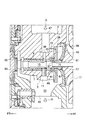
- FIG. 1 is a side sectional view of a supercharger for a vehicle according to an embodiment of the present invention.
- FIG. 2 is an enlarged view of the arrow II in FIG.
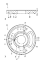
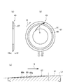
- FIG. 3A is a view showing a rear side surface (back surface) of the first thrust bearing according to the embodiment of the present invention
- FIG. 3B is a side sectional view of the first thrust bearing.
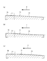
- FIG. 4A is a cross-sectional view of the first bearing pad along a predetermined oil droplet trajectory
- FIG. 4B and FIG. 4C are modified examples thereof.
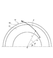
- FIG. 5 is a diagram for explaining a radial component and an angular component (circumferential component) of an oil droplet trajectory.
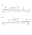
- FIG. 6A is a side sectional view of a second thrust bearing according to an embodiment of the present invention
- FIG. 6B is a diagram showing a front side surface (front) of the second thrust bearing
- FIG. These are sectional drawings of the 2nd bearing pad of Drawing 6 (b) along the track of a predetermined oil drop.
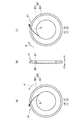
- FIG. 7A is a view showing a rear side (rear surface) of a thrust collar according to an embodiment of the present invention
- FIG. 7B is a side sectional view of the thrust collar according to an embodiment of the present invention.
- FIG. 7C is a view showing the front side surface of the thrust collar according to the embodiment of the present invention.
- FIG. 8A is a cross-sectional view of the first color pad along a predetermined oil droplet trajectory
- FIG. 8B is a cross-sectional view of the second color pad along the predetermined oil droplet trajectory.
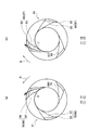
- FIG. 9 is a view illustrating a rear side surface of the first thrust bearing according to the embodiment of the present invention.
- FIG. 10 is a view showing a front side surface of the second thrust bearing according to the embodiment of the present invention.
- FIG. 11A is a diagram showing a rear side (back) of a thrust collar according to an embodiment of the present invention
- FIG. 11B is a diagram showing a front side of the thrust collar according to an embodiment of the present invention. It is.
- FIG. 1 and FIG. 2 show a supercharger 1 according to this embodiment.
- the supercharger 1 is used, for example, in a vehicle, and supercharges (compresses) air supplied to the engine using energy of exhaust gas from an engine (not shown).
- the supercharger 1 includes a housing (bearing housing) 3.
- the housing 3 has a support block 5 that constitutes a part of the housing 3 inside thereof.
- An installation hole 7 extending in the front-rear direction is formed through the support block 5.
- a semi-floating metal 9 as an example of a radial bearing is installed.
- a rotation stop pin 11 is inserted into the side surface of the semi-floating metal 9 via the support block 5 to prevent the semi-floating metal 9 from rotating.
- a through hole 13 is formed through the intermediate portion of the semi-floating metal 9.
- the semi-floating metal 9 rotatably supports a rotor shaft 15 extending in the front-rear direction.
- the rotor shaft 15 is rotatably provided on the support block 5 via the semi-floating metal 9.
- a compressor impeller 17 and a turbine impeller 27 are respectively attached to the front end and the rear end of the rotor shaft 15. Therefore, the compressor impeller 17, the turbine impeller 27, and the rotor shaft 15 rotate integrally.
- the compressor impeller 17 compresses gas (for example, air) using centrifugal force.
- the turbine impeller 27 generates a rotational force using the pressure energy of the exhaust gas.
- the compressor housing 19 is provided on the front side of the housing 3 and accommodates the compressor impeller 17.
- the compressor housing 19 has an intake port 21, a diffuser 22, a spiral scroll channel (compressor scroll channel) 23, and a discharge port 25.
- the intake port 21 opens toward the front of the supercharger 1 so as to communicate with the inlet side of the compressor impeller 17.
- the diffuser 22 is formed on the outlet side of the compressor impeller 17 and decelerates and compresses the gas discharged from the compressor impeller 17.
- the scroll channel 23 is provided so as to communicate with the outlet side of the diffuser 22, and the discharge port 25 is formed so as to communicate with the outlet side of the scroll channel 23. Accordingly, the compressed gas decelerated by the diffuser 22 passes through the scroll flow path 23 and is discharged from the discharge port 25.
- the turbine housing 29 is provided on the rear side of the housing 3 and accommodates the turbine impeller 27.
- the turbine housing 29 includes an intake port 31, a spiral scroll channel (turbine scroll channel) 33, and a discharge port 35.
- the intake port 31 is formed so as to communicate with the inlet side of the scroll channel 33, and the scroll channel 33 is provided so that the outlet side thereof communicates with the inlet side of the turbine impeller 27.
- the discharge port 35 opens toward the rear of the supercharger 1 so as to communicate with the outlet side of the turbine impeller 27. Therefore, the exhaust gas flowing in from the intake port 31 passes through the scroll flow path 33 and flows into the turbine impeller 27.
- the exhaust gas flowing into the turbine impeller 27 drives and rotates the turbine impeller 27 by its pressure. Thereafter, the exhaust gas is discharged from the discharge port 35.
- variable nozzle mechanism 37 that varies the flow area (flow rate) of the exhaust gas supplied to the turbine impeller 27 side may be disposed.
- the variable nozzle mechanism 37 has a known configuration. Accordingly, the detailed description of the variable nozzle mechanism 37 is omitted, and the contents of, for example, Japanese Patent Application Laid-Open Nos. 2009-243300 and 2009-243431 are incorporated as part of the present specification.
- the supercharger 1 is provided with a thrust bearing structure 39.
- the thrust bearing structure 39 supports the axial thrust load acting on the rotor shaft 15 by utilizing the wedge effect of the lubricating oil G.
- the thrust bearing structure 39 includes a thrust collar 41 fixed to the rotor shaft 15, a thrust bearing (first thrust bearing) 43 provided on the front side of the thrust collar 41, and a thrust bearing (first bearing) provided on the rear side of the thrust collar 41. 2 thrust bearings) 45.
- the thrust bearing 43 supports a forward thrust load
- the thrust bearing 45 supports a backward thrust load. The details of the thrust bearing structure 39 will be described later.
- the housing 3 has an oil supply port 47 formed in an upper portion thereof (an upper portion of the housing 3 shown in FIG. 2), and an oil supply passage (first oil supply passage) 49 formed in the support block 5. And an oil supply passage (second oil supply passage) 51 formed in the support block 5.
- the oil supply port 47 takes in the lubricating oil G.
- the oil supply passage 49 communicates the oil supply port 47 with the installation hole 7 and supplies the lubricating oil G between the semi-floating metal 9 and the rotor shaft 15.
- the oil supply passage 51 connects the oil supply port 47 to the installation location of the thrust bearing structure 39 to supply the lubricating oil G between the thrust bearing 43 and the thrust collar 41 and between the thrust bearing 45 and the thrust collar 41. .
- the housing 3 has a receiving chamber 53 for receiving the lubricating oil G below the support block 5 (downward in FIG. 2).
- an oil drain port 55 is formed in the lower portion of the receiving chamber 53. The lubricating oil G flowing into the receiving chamber 53 is discharged to the outside of the housing 3 through the oil discharge port 55.
- an oil drain 57 is fixed to the rotor shaft 15.
- the oil drain 57 is located between the compressor impeller 17 and the thrust collar 41.
- An annular seal plate 59 is provided so as to surround the outer peripheral surface of the oil drain 57.
- a seal ring 61 is provided between the outer peripheral surface of the oil drainer 57 and the inner peripheral surface of the seal plate 59. The seal ring 61 suppresses leakage of the lubricating oil G from the inside of the housing 3 to the installation space of the compressor impeller 17 and leakage of gas (air) from the installation space of the compressor impeller 17 to the inside of the housing 3.
- an insertion hole 63 for allowing the rotor shaft 15 to be inserted is formed in the rear side portion of the housing 3.
- a seal ring 65 is provided between the insertion hole 63 and the outer peripheral surface of the rotor shaft 15. The seal ring 65 suppresses leakage of the lubricating oil G from the inside of the housing 3 to the installation space of the turbine impeller 27 and leakage of exhaust gas from the installation space of the turbine impeller 27 to the inside of the housing 3.
- the thrust bearing structure 39 includes a thrust collar 41.
- the thrust collar 41 is formed in a flat annular shape, and is fixed to the rotor shaft 15 penetrating the center.
- the thrust collar 41 has a color pad (first color pad) 67 on the front surface.
- the color pad 67 is formed as an annular plane orthogonal to the rotor shaft 15.
- the thrust collar 41 has a color pad (second color pad) 69 on the back surface. Similar to the color pad 67, the color pad 69 is formed as an annular plane orthogonal to the rotor shaft 15.
- the thrust bearing structure 39 includes a thrust bearing (first thrust bearing) 43 provided on the front side of the thrust collar 41.
- the thrust bearing 43 supports a forward thrust load transmitted through the thrust collar 41.
- the thrust bearing 43 has a bearing pad (first bearing pad) 71 on the surface of the thrust collar 41 facing the color pad 67.
- Lubricating oil G is interposed between the bearing pad 71 and the color pad 67. Therefore, due to the wedge effect (described later) of the lubricating oil G, the thrust collar 41 can rotate smoothly on the thrust bearing 43 while the above-described thrust load is generated.
- the bearing pad 71 has a tapered portion 73 and a land portion 75 formed continuously on the outer edge of the tapered portion 73. Both the taper portion 73 and the land portion 75 are formed in an annular shape when viewed from the rotation axis direction (front-rear direction).
- the tapered portion 73 has a slope formed so that the thickness gradually increases toward the downstream side along a predetermined oil droplet trajectory (trajectory direction) T. .
- a predetermined oil droplet trajectory T is simply referred to as a trajectory T.
- this slope may have a certain inclination so as to include the straight line L1, and as shown in FIG. 4 (b), it protrudes downward with respect to the straight line L1.
- FIG. 4C it may be formed so as to protrude upward with respect to the straight line L1.
- the land portion 75 has a flat surface formed so as to be continuous to the downstream side of the tapered portion 73 in the track T. This plane is orthogonal to the axis of the rotor shaft 15. Accordingly, the thickness of the land portion 75 is constant along the circumferential direction.
- the track T assumes oil droplets of the lubricating oil G supplied between the bearing pad 71 and the color pad 67, and the rotational speed of the rotor shaft 15 during operation of the supercharger 1 is constant. This is the trajectory of the oil droplet when it is assumed.
- the moving direction of the oil droplet is determined based on the centrifugal force applied to the oil droplet generated by the rotation of the rotor shaft 15. That is, the trajectory T shows the trajectory of the oil droplet that moves under the influence of the centrifugal force.
- FIG. 5 shows the pad 12 including the tapered portion 14 having the above-described slope and the land portion 16 having the above-described plane.
- a polar coordinate system centering on the center O of the pad 12 is adopted, and the oil droplets are rotated counterclockwise around the center O at a constant speed.
- the radial direction component r and angle component are the centrifugal force during rotation.
- P corresponds to trajectory T in FIG. 3 and trajectory S in FIG.
- the thrust bearing 43 has an arcuate recess 77 and a storage pocket 85 on the back surface thereof.
- the recess 77 and the storage pocket 85 are both located on the outer periphery of the bearing pad 71.
- the storage pocket 85 communicates with the recess 77. That is, the storage pocket 85 is formed in the lower part of the back surface of the thrust bearing 43 so that a part of the storage pocket 85 is sandwiched between both ends of the recess 77.
- the recess 77 receives the lubricating oil G discharged from the land portion 75 of the bearing pad 71.
- the storage pocket 85 since the storage pocket 85 is adjacent to the land portion 75, the same function as the concave portion 77 is achieved.
- the storage pocket 85 also has a concave portion 77 that is wide in the radial direction, the lubricating oil G that has flowed into the concave portion 77 can also be temporarily stored.
- the thrust bearing 43 has a plurality of oil supply pockets 79 and grooves 81 on the back surface thereof.
- the oil supply pocket 79 is formed on the outer side of the concave portion 77 in the radial direction with an interval in the circumferential direction.
- three oil supply pockets 79 are formed, and among these, the central oil supply pocket 79 is positioned so as to face the opening of the oil supply passage 51.
- the groove 81 is formed in an arc shape at the peripheral edge of the back surface of the thrust bearing 43, and communicates the plurality of oil supply pockets 79. Therefore, in the form of FIG. 3A, each oil supply pocket 79 communicates with the oil supply passage 51 via the groove 81 except for the central oil supply pocket 79.
- the thrust bearing 43 has a communication passage 83 communicating with the oil supply pocket 79.
- the communication passage 83 is a through hole, one end of which opens to the corresponding oil supply pocket 79, and the other end opens at the tapered portion 73 of the bearing pad 71. Accordingly, the lubricating oil G supplied from the oil supply passage 51 passes through the oil supply pocket 79, and in some cases also passes through the groove 81, and reaches the tapered portion 73 via the communication passage 83.
- the thrust bearing structure 39 includes a thrust bearing (second thrust bearing) 45 provided on the rear side of the thrust collar 41.
- the thrust bearing 45 supports a backward thrust load transmitted through the thrust collar 41.
- the thrust bearing 45 has a bearing pad (second bearing pad) 87 on the surface of the thrust collar 41 facing the color pad 69.
- Lubricating oil G is interposed between the bearing pad 87 and the color pad 69. Therefore, due to the wedge effect (described later) of the lubricating oil G, the thrust collar 41 can rotate smoothly on the thrust bearing 45 while the above-described thrust load is generated.
- the bearing pad 87 has a tapered portion 89 and a land portion 91 formed continuously on the outer edge of the tapered portion 89. Both the taper portion 89 and the land portion 91 are formed in an annular shape when viewed from the rotation axis direction (front-rear direction).
- the tapered portion 89 has a slope formed so that the thickness gradually increases toward the downstream side along a predetermined oil droplet trajectory (orbit direction) S. .
- the taper portion 89 approaches a surface (for example, the color pad 69 of the thrust collar 41) that is in front of the bearing pad 87 and orthogonal to the axis of the rotor shaft 15 as the taper portion 89 moves away from the axis of the rotor shaft 15. It has a slope formed as follows. When a circle with an arbitrary radius centered on the axis of the rotor shaft 15 is assumed, the thickness of the tapered portion 89 on the circle is constant.
- the change of the inclination is arbitrary. That is, as shown in FIG. 6C, the slope may have a certain slope so as to include the straight line L2, and the slope is lowered with respect to the straight line L2, as in a tapered portion 89a indicated by a one-dot chain line. You may form so that it may become convex. Furthermore, the inclined surface may be formed so as to protrude upward with respect to the straight line L2, as in a tapered portion 89b indicated by a one-dot chain line.
- the land portion 91 has a flat surface formed so as to be continuous to the downstream side of the tapered portion 89 in the track S. This plane is orthogonal to the axis of the rotor shaft 15. Accordingly, the thickness of the land portion 91 is constant along the circumferential direction.
- the track S assumes oil droplets of the lubricating oil G supplied between the bearing pad 87 and the color pad 69, and the rotational speed of the rotor shaft 15 during operation of the supercharger 1 is constant. This is the trajectory of the oil droplet when it is assumed.
- the moving direction of the oil droplet is determined based on the centrifugal force applied to the oil droplet generated by the rotation of the rotor shaft 15. That is, the trajectory S indicates the trajectory of the oil droplet that moves under the influence of the centrifugal force.
- the direction of the trajectory S is the same as the direction of the trajectory T.
- the thrust bearing structure 39 is not limited to the above-described configuration, and can be changed as follows, for example.
- the collar pad 67 of the thrust collar 41 may have the same structure as the bearing pad 87 of the thrust bearing 45. That is, the color pad 67 may include a taper portion 93 and a land portion 95 formed continuously on the outer edge of the taper portion 93. In this case, both the taper portion 93 and the land portion 95 are formed in an annular shape centering on the axis of the rotor shaft 15 when viewed from the rotation axis direction (front-rear direction).
- the bearing pad 71 of the thrust bearing 43 is formed as a plane orthogonal to the rotor shaft 15.
- the taper portion 93 has a slope formed so that the thickness gradually increases along the track T toward the downstream side thereof.
- the taper portion 93 moves away from the axis of the rotor shaft 15, the taper portion 93 approaches a surface (for example, the bearing pad 71 of the thrust bearing 43) that is in front of the thrust collar 41 and orthogonal to the axis of the rotor shaft 15. It has a slope formed in.
- the thickness of the tapered portion 93 on the circle is constant.
- the land portion 95 has a flat surface formed so as to continue to the downstream side of the tapered portion 93 in the track T. This plane is orthogonal to the axis of the rotor shaft 15. Accordingly, the thickness of the land portion 95 is constant along the circumferential direction.
- the change of the inclination is arbitrary. That is, the slope may have a certain inclination so as to include the straight line L3, may be formed to be convex downward with respect to the straight line L3, and may be convex upward with respect to the straight line L3. (See FIGS. 4 (a) to 4 (c) for similar examples).
- the collar pad 69 of the thrust collar 41 may have the same structure as the bearing pad 71 of the thrust bearing 43. That is, the color pad 69 may include a tapered portion 97 and a land portion 99 formed continuously on the outer edge of the tapered portion 97. In this case, both the taper portion 97 and the land portion 99 are formed in an annular shape centering on the axis of the rotor shaft 15 when viewed from the rotation axis direction (front-rear direction).
- the bearing pad 87 of the thrust bearing 45 is formed as a plane orthogonal to the rotor shaft 15.
- the tapered portion 97 has a slope formed so that the thickness gradually increases along the track S toward the downstream side thereof.
- the taper portion 97 moves away from the axis of the rotor shaft 15, the taper portion 97 approaches the surface (for example, the bearing pad 87 of the thrust bearing 45) behind the thrust collar 41 and orthogonal to the axis of the rotor shaft 15. It has a slope formed in.
- the thickness of the tapered portion 93 on the circle is constant.
- the land portion 99 has a flat surface formed so as to be continuous to the downstream side of the tapered portion 93 in the track S. This plane is orthogonal to the axis of the rotor shaft 15. Accordingly, the thickness of the land portion 99 is constant along the circumferential direction.
- the change of the inclination is arbitrary. That is, the slope may have a certain inclination so as to include the straight line L4, may be formed to be convex downward with respect to the straight line L4, and may be convex upward with respect to the straight line L4. (See FIGS. 4 (a) to 4 (c) for similar examples).
- the bearing pad 71 of the thrust bearing 43 is composed of a plurality of pads 72 having a tapered portion 73 and a land portion 75 and arranged at predetermined angles along the circumferential direction. Also good.
- each pad 72 has a pair of edge portions 72a and 72b formed along the track T, and a pair of arc-shaped edge portions 72c and 72d made of arcs having different radii.
- the initial position of each oil droplet assumed in the shape determination of the edge part 72a and the edge part 72b exists on the same circle including the circular arc-shaped edge part 72c, it is mutually spaced apart in the circumferential direction.
- the arc-shaped edge 72c defines the inner edge of the tapered portion 73 in the radial direction
- the arc-shaped edge 72d defines the outer edge of the land portion 75 in the radial direction.
- each pad 72 is formed in a substantially sector shape when viewed from the axial direction (front-rear direction).
- the edges 72a and 72b extend in the direction in which the track T travels. That is, the lubricating oil G (oil droplet) in the space sandwiched between the edge portion 72a and the edge portion 72b can reach the land portion 75 along the track P shown in FIG.
- the bearing pad 87 of the thrust bearing 45 may have the same configuration as the bearing pad 71 shown in FIG. That is, as shown in FIG. 10, the bearing pad 87 may be composed of a plurality of pads 88 having a tapered portion 89 and a land portion 91 and arranged at predetermined angles along the circumferential direction. .
- each pad 88 has a pair of edge portions 88a and 88b formed along the track S, and a pair of arc-shaped edge portions 88c and 88d made of arcs having different radii.
- each pad 88 is formed in a substantially sector shape when viewed from the axial direction (front-rear direction).
- edges 88a and 88b extend in the direction in which the track S travels. That is, the lubricating oil G (oil droplet) in the space sandwiched between the edge portion 88a and the edge portion 88b can reach the land portion 91 along the track P shown in FIG.
- the color pad 67 and the color pad 69 of the thrust collar 41 may have the same configuration as the bearing pad 71 shown in FIG. 9 and the bearing pad 87 shown in FIG. That is, as shown in FIG. 11B, the color pad 67 is composed of a plurality of pads 68 each having a tapered portion 93 and a land portion 95 and arranged at predetermined angles along the circumferential direction. May be.
- the color pad 69 may include a plurality of pads 70 each having a tapered portion 97 and a land portion 99 and arranged at predetermined angles. These pads 68 and 70 have the same shape as the pad 72 of FIG. 9 and the pad 88 of FIG. Therefore, the detailed description here is omitted.
- Exhaust gas taken in from the gas inlet 31 flows from the inlet side to the outlet side of the turbine impeller 27 via the turbine scroll flow path 33. At this time, the pressure energy of the exhaust gas rotates the turbine impeller 27.
- the compressor impeller 17 is connected to the turbine impeller 27 via the rotor shaft 15. Therefore, the rotor shaft 15 and the compressor impeller 17 rotate integrally with the turbine impeller 27. Therefore, the gas (for example, air) can be taken in from the inlet 21 by rotation of the compressor impeller 17, and further, the taken-in gas can be compressed. The compressed gas is discharged from the discharge port 25 via the scroll flow path 23. Therefore, gas can be supercharged to the engine or the like.
- the lubricating oil G is supplied between the semi-floating metal 9 and the rotor shaft 15 via the oil supply port 47 and the oil supply passage 49. Therefore, the lubricating oil G functions as a lubricant between the semi-floating metal 9 and the rotor shaft 15 and prevents seizure or the like between them. Note that the lubricating oil G supplied between the semi-floating metal 9 and the rotor shaft 15 is discharged from the oil discharge port 55 to the outside of the housing 3 through the receiving chamber 53.
- the lubricating oil G flows between the thrust bearing 43 and the thrust collar 41 and between the thrust bearing 45 and the thrust collar 41 via the oil supply passage 51, the oil supply pocket 79, the communication passage 83, and the like. Supplied between. At this time, the space between the bearing pad 71 and the color pad 67 and the space between the bearing pad 87 and the color pad 69 are also filled with the lubricating oil G. As a result, the wedge effect of the lubricating oil G is generated by the cooperation of the bearing pad 71 and the collar pad 67, and the forward thrust load acting on the rotor shaft 15 can be supported by this wedge effect. Further, the wedge effect of the lubricating oil G is generated by the cooperation of the bearing pad 87 and the color pad 69, and the backward thrust load acting on the rotor shaft 15 can be supported.
- either one of the bearing pad and the color pad facing each other is provided with a tapered portion.
- the tapered portion is a slope that is inclined so as to gradually increase in thickness toward the downstream side along a predetermined oil droplet trajectory (see FIG. 5), and the outer edge (downstream end portion) of the slope. Land portions are continuously formed. Therefore, compared with the case where it inclines along the rotation direction R of a rotor axis
- the ratio (contribution rate) of the lubricating oil G that contributes to the wedge effect in the lubricating oil G supplied between the bearing pad and the color pad can be increased, and the wedge effect by the lubricating oil G is sufficiently and efficiently used. Can be demonstrated well.
- the thrust bearing structure of the present embodiment can obtain a high support capability against the thrust load.
- this invention is not restricted to description of the above-mentioned embodiment, For example, it can implement in various aspects, such as using the above-mentioned thrust bearing structure for rotating machines other than a supercharger. Further, the scope of rights encompassed by the present invention is not limited to these embodiments.
- the ratio of the lubricating oil supplied between the bearing pad and the collar pad in the thrust bearing structure that contributes to the wedge effect can be increased, and the wedge effect can be exhibited sufficiently and efficiently. Therefore, it is possible to provide a thrust bearing structure having a high support capability against a thrust load and a supercharger including the thrust bearing structure.
Landscapes
- Engineering & Computer Science (AREA)
- General Engineering & Computer Science (AREA)
- Mechanical Engineering (AREA)
- Physics & Mathematics (AREA)
- Fluid Mechanics (AREA)
- Chemical & Material Sciences (AREA)
- Oil, Petroleum & Natural Gas (AREA)
- Combustion & Propulsion (AREA)
- Supercharger (AREA)
- Sliding-Contact Bearings (AREA)
Abstract
スラスト軸受構造(39)は、カラーパッド(67)を有するスラストカラー(41)と、スラストカラーに対向する面のカラーパッド(67)に対応する位置に軸受パッド(71)を有するスラスト軸受(43)とを備える。軸受パッド(71)は、テーパ部(73)と、テーパ部(73)の外縁に連続して形成されるランド部(75)とを有する。軸受パッド(71)とカラーパッド(67)との間に供給された油滴を仮定し、且つ、ロータ軸(15)の回転速度が一定であると仮定した場合、テーパ部(73)は、ロータ軸(15)の回転により油滴に働く遠心力に基づいて所定の油滴の軌道Tに沿ってその下流側に向けて肉厚を徐々に厚くするように形成された斜面を有する。
Description
本発明は、軸方向に発生するスラスト荷重を支持するスラスト軸受構造及び当該スラスト軸受構造を備える過給機に関する。
回転機械の一例として知られる過給機は、ハウジングと、このハウジングに回転可能に設けられたロータ軸と、このロータ軸の一端に取り付けられたコンプレッサインペラと、このロータ軸の他端に取り付けられたタービンインペラとを備えている。コンプレッサインペラは、遠心力を利用して空気を圧縮し、タービンインペラは、排気ガスの圧力エネルギーを利用して回転力を発生させる。コンプレッサインペラとタービンインペラはロータ軸を介して互いに連結されているので、これらは一体的に回転する。この回転時、ロータ軸は回転方向だけでなく、軸方向にも荷重を受ける。従って、過給機は、軸方向の荷重(所謂スラスト荷重)を支持するスラスト軸受構造を有する。
このスラスト軸受構造に関して、特許文献1は、潤滑油の楔効果を利用したものを開示している。特許文献1のスラスト軸受構造は、スラストカラーとスラスト軸受とを有する。スラストカラーとスラスト軸受は何れも環状に形成され、ロータ軸の軸方向に沿って互いが対向するように配列している。スラストカラーはロータ軸に固定され、当該ロータ軸と共に一体的に回転する。
また、スラストカラーは、その一面にカラーパッドを有している。カラーパッドの表面は、ロータ軸の軸心に直交している。一方、スラスト軸受は、カラーパッドと対向する面に複数の軸受パッドを有する。各軸受パッドは、テーパ部と、ランド部とを有する。テーパ部の表面は、ロータ軸の回転方向に沿って徐々にカラーパッドに接近するように傾斜している。換言すれば、テーパ部は、その肉厚がロータ軸の回転方向に沿って徐々に厚くなるように形成されている。ランド部の表面はロータ軸の軸心に直交しており、テーパ部の回転方向側に連続している。つまり、スラストカラーのカラーパッドとスラスト軸受の軸受パッドとが互いに対向したとき、両者の間隔は、ランド部において最も狭くなる。
また、スラストカラーは、その一面にカラーパッドを有している。カラーパッドの表面は、ロータ軸の軸心に直交している。一方、スラスト軸受は、カラーパッドと対向する面に複数の軸受パッドを有する。各軸受パッドは、テーパ部と、ランド部とを有する。テーパ部の表面は、ロータ軸の回転方向に沿って徐々にカラーパッドに接近するように傾斜している。換言すれば、テーパ部は、その肉厚がロータ軸の回転方向に沿って徐々に厚くなるように形成されている。ランド部の表面はロータ軸の軸心に直交しており、テーパ部の回転方向側に連続している。つまり、スラストカラーのカラーパッドとスラスト軸受の軸受パッドとが互いに対向したとき、両者の間隔は、ランド部において最も狭くなる。
カラーパッドとスラスト軸受の間は潤滑油で満たされている。ロータ軸がカラーパッドと共に回転するとき、この回転と潤滑油の粘性によって潤滑油は回転方向に流動する。一方、上述の通り、カラーパッド‐軸受パッドの間隔はランド部において最も狭くなる。つまり、潤滑油の流動はランド部とカラーパッドとの間に集中するため、ランド部及びテーパ部におけるランド部側では潤滑油内の圧力が上昇し、カラーパッドとスラスト軸受を互いに離間させる。このような効果を一般的に楔効果と呼んでいる。過給機の運転中は、この楔効果により、ロータ軸に働くスラスト荷重を支持することができる。
回転機械において、スラスト荷重に対する高い支持能力の確保が急務になっている。これは、過給機の場合は、圧力比又は膨張比等の向上が強く要請されており、これに伴い、ロータ軸に働くスラスト荷重が増大するからである。
本発明は、負荷能力を高いレベルまで確保することができる、新規な構成のスラスト軸受構造及び当該スラスト軸受構造を備える過給機を提供することを目的とする。
本発明の第1の態様は、ロータ軸に働く軸方向のスラスト荷重を支持するスラスト軸受構造であって、回転可能なロータ軸に固定されるスラストカラーと、前記スラストカラーに対向するスラスト軸受とを備え、前記スラストカラーは前記スラスト軸受に対向する面にカラーパッドを有し、前記スラスト軸受は前記スラストカラーに対向する面の前記カラーパッドに対応する位置に軸受パッドを有し、前記カラーパッド及び前記軸受パッドのうちの何れかのパッドは、テーパ部と、前記テーパ部の外縁に連続して形成されるランド部とを有し、前記軸受パッドと前記カラーパッドとの間の油滴を仮定した場合、テーパ部は、前記ロータ軸の回転によって発生する前記油滴への遠心力に基づいて決定される前記油滴の軌道に沿ってその下流側に向けて肉厚が徐々に厚くなるように形成された斜面を有し、前記ランド部は前記ロータ軸の軸心に直交する平面を有することを要旨とする。
本発明の第2の態様は、エンジンからの排気ガスのエネルギーを利用して、前記エンジン側に供給される空気を過給する過給機であって、ハウジングと、前記ハウジングに回転可能に設けられる前記ロータ軸と、前記ロータ軸の一端に取り付けられ、遠心力を利用してガスを圧縮するコンプレッサインペラと、前記ロータ軸の他端に取り付けられ、ガスの圧力エネルギーを利用して回転力を発生させるタービンインペラと、前記ロータ軸に働く軸方向のスラスト荷重を支持するスラスト軸受構造とを備え、前記スラスト軸受構造は、前記ロータ軸に固定されるスラストカラーと、前記スラストカラーに対向するスラスト軸受とを有し、前記スラストカラーは前記スラスト軸受に対向する面にカラーパッドを有し、前記スラスト軸受は前記スラストカラーに対向する面の前記カラーパッドに対応する位置に軸受パッドを有し、前記カラーパッド及び前記軸受パッドのうちの何れかのパッドは、テーパ部と、前記テーパ部の外縁に連続して形成されるランド部とを有し、前記軸受パッドと前記カラーパッドとの間の油滴を仮定した場合、テーパ部は、前記ロータ軸の回転によって発生する前記油滴への遠心力に基づいて決定される前記油滴の軌道に沿ってその下流側に向けて肉厚が徐々に厚くなるように形成された斜面を有し、前記ランド部は前記ロータ軸の軸心に直交する平面を有することを要旨とする。
前記何れかのパッドは、環状に形成されてもよい。
前記何れかのパッドは、円周方向に沿って複数設けられてもよい。
前記油滴の軌道は、前記ロータ軸の回転速度が一定であることを仮定した場合の軌道であってもよい。
本発明によれば、負荷能力を高いレベルまで確保することができる、新規な構成のスラスト軸受構造及び当該スラスト軸受構造を備える過給機を提供することができる。
本発明の一実施形態について図1から図10を参照して説明する。図面中、「FF」は前方向を指し、「FR」は後方向を指してある。なお、これらの方向は本発明を限定するものではない。
本実施形態に係る過給機1を図1及び図2に示す。過給機1は、例えば車両に使用され、エンジン(図示省略)からの排気ガスのエネルギーを利用して、エンジンに供給される空気を過給(圧縮)するものである。
過給機1は、ハウジング(軸受ハウジング)3を備える。ハウジング3は、その内側にハウジング3の一部分を構成する支持ブロック5を有する。支持ブロック5には、前後方向に延びた設置穴7が貫通形成されている。
設置穴7内には、ラジアル軸受の一例としてのセミフローティングメタル9が設置されている。セミフローティングメタル9の側面には、支持ブロック5を介して回止めピン11が挿入され、セミフローティングメタル9の回転を阻止している。なお、セミフローティングメタル9の中間部には、通孔13が貫通形成されている。
セミフローティングメタル9は、前後方向へ延びるロータ軸15を回転可能に支持する。換言すれば、支持ブロック5には、ロータ軸15がセミフローティングメタル9を介して回転可能に設けられている。ロータ軸15の前端及び後端には、コンプレッサインペラ17及びタービンインペラ27がそれぞれ取り付けられている。従って、コンプレッサインペラ17、タービンインペラ27、及びロータ軸15は一体的に回転する。コンプレッサインペラ17は、遠心力を利用してガス(例えば空気)を圧縮する。タービンインペラ27は、排気ガスの圧力エネルギーを利用して回転力を発生させる。
コンプレッサハウジング19はハウジング3の前側に設けられており、コンプレッサインペラ17を収容する。また、コンプレッサハウジング19は、取入口21と、ディフューザ22と、渦巻き状のスクロール流路(コンプレッサスクロール流路)23と、排出口25とを有する。取入口21は、コンプレッサインペラ17の入口側と連通するように、過給機1の前方に向かって開口している。ディフューザ22は、コンプレッサインペラ17の出口側に形成され、コンプレッサインペラ17から排出されたガスの減速及び圧縮を行う。スクロール流路23はディフューザ22の出口側に連通するように設けられ、排出口25はスクロール流路23の出口側と連通するように形成される。従って、ディフューザ22によって減速した圧縮ガスは、スクロール流路23を通過し、排出口25から排出される。
タービンハウジング29はハウジング3の後側に設けられ、タービンインペラ27を収容する。タービンハウジング29は、取入口31と、渦巻き状のスクロール流路(タービンスクロール流路)33と、排出口35とを有する。取入口31は、スクロール流路33の入口側と連通するように形成され、スクロール流路33は、その出口側がタービンインペラ27の入口側に連通するように設けられる。排出口35はタービンインペラ27の出口側と連通するように、過給機1の後方に向かって開口している。従って、取入口31から流入した排気ガスは、スクロール流路33を通過し、タービンインペラ27に流入する。タービンインペラ27に流入した排気ガスは、その圧力によってタービンインペラ27を駆動し、回転させる。その後、排気ガスは排出口35から排出される。
タービンハウジング29内におけるスクロール流路33とタービンインペラ27との間には、タービンインペラ27側へ供給される排気ガスの流路面積(流量)を可変する可変ノズル機構37を配設してもよい。なお、可変ノズル機構37は、公知の構成からなるものである。従って、可変ノズル機構37の詳細についての説明は省略し、本明細書の一部を構成するものとして、例えば特開2009-243300号公報、特開2009-243431号公報の内容を援用する
図2に示すように、過給機1はスラスト軸受構造39を備えている。スラスト軸受構造39は、潤滑油Gの楔効果を利用してロータ軸15に働く軸方向のスラスト荷重を支持する。スラスト軸受構造39は、ロータ軸15に固定されたスラストカラー41と、スラストカラー41の前側に設けられるスラスト軸受(第1スラスト軸受)43と、スラストカラー41の後側に設けられるスラスト軸受(第2スラスト軸受)45とを備えている。スラスト軸受43は前方向のスラスト荷重を支持し、スラスト軸受45は後方向のスラスト荷重を支持する。なお、スラスト軸受構造39の詳細は後述する。
図2に示すように、ハウジング3は、その上部(図2に示すハウジング3の上部分)に形成された給油口47と、支持ブロック5に形成された給油通路(第1給油通路)49と、支持ブロック5に形成された給油通路(第2給油通路)51とを有する。給油口47は潤滑油Gを取入れる。給油通路49は給油口47を設置穴7に連通させ、セミフローティングメタル9とロータ軸15との間に潤滑油Gを供給する。更に、給油通路51は、給油口47をスラスト軸受構造39の設置箇所に連通させ、スラスト軸受43とスラストカラー41との間及びスラスト軸受45とスラストカラー41との間に潤滑油Gを供給する。
図2に示すように、ハウジング3は、支持ブロック5の下方(図2における下方)に潤滑油Gを受容する受容室53を有する。また、受容室53の下部には排油口55が形成されている。受容室53に流入した潤滑油Gは、排油口55を介してハウジング3の外側に排出される。
図2に示すように、ロータ軸15には油切り57が固定されている。油切り57は、コンプレッサインペラ17とスラストカラー41の間に位置する。また、環状のシールプレート59が油切り57の外周面を囲むように設けられている。油切り57の外周面とシールプレート59の内周面との間には、シールリング61が設けられている。シールリング61は、ハウジング3の内側からコンプレッサインペラ17の設置空間への潤滑油Gの漏れ及びコンプレッサインペラ17の設置空間からハウジング3の内側へのガス(空気)の漏れを抑制する。
図2に示すように、ハウジング3の後側部には、ロータ軸15の挿入を可能にするための挿入穴63が形成されている。この挿入穴63とロータ軸15の外周面との間には、シールリング65が設けられている。シールリング65は、ハウジング3の内側からタービンインペラ27の設置空間への潤滑油Gの漏れ及びタービンインペラ27の設置空間からハウジング3の内側への排気ガスの漏れを抑制する。
続いて、本実施形態に係るスラスト軸受構造39の構成について詳細に説明する。
図2に示すように、スラスト軸受構造39はスラストカラー41を備える。スラストカラー41は扁平な環状に形成され、その中心を貫くロータ軸15に固定されている。スラストカラー41は、前面にカラーパッド(第1カラーパット)67を有する。カラーパッド67は、ロータ軸15に直交する環状の平面として形成されている。また、スラストカラー41は、背面に、カラーパッド(第2カラーパッド)69を有する。カラーパッド69は、カラーパッド67と同様に、ロータ軸15に直交する環状の平面として形成されている。
スラスト軸受構造39は、スラストカラー41の前側に設けられたスラスト軸受(第1スラスト軸受)43を備える。スラスト軸受43は、スラストカラー41を介して伝わる前方向のスラスト荷重を支持する。スラスト軸受43は、スラストカラー41のカラーパッド67と対向する面に軸受パッド(第1軸受パッド)71を有する。軸受パッド71とカラーパッド67の間には潤滑油Gが介在する。従って、潤滑油Gの楔効果(後述)によって、上述のスラスト荷重が発生している間も、スラストカラー41はスラスト軸受43上で滑らかに回転することができる。
図3(a)に示すように、軸受パッド71はテーパ部73と、テーパ部73の外縁に連続して形成されたランド部75とを有する。テーパ部73及びランド部75は何れも、回転軸方向(前後方向)から見て、環状に形成されている。
図4(a)に示すように、テーパ部73は、所定の油滴の軌道(軌道方向)Tに沿ってその下流側に向けて肉厚が徐々に厚くなるように形成された斜面を有する。換言すると、テーパ部73は、ロータ軸15の軸心から離れるに連れて、軸受パッド71後方の、ロータ軸15の軸心に直交する面(例えば、スラストカラー41のカラーパッド67)に近づくように形成された斜面を有する。ロータ軸15の軸心を中心とした任意の半径の円を想定した場合、この円上にあるテーパ部73の肉厚は一定である。以下、説明の便宜上、所定の油滴の軌道Tを単に軌道Tと称する。
なお、テーパ部73の斜面は、軌道Tの下流側に向けて当該テーパ部73の肉厚が徐々に厚くなるように形成される限り、その傾きの変化は任意である。即ち、図4(a)に示す如く、この斜面は直線L1を含むように一定の傾きを有してもよく、図4(b)に示すように、直線L1に対して下に凸となるように形成してもよく、更には、図4(c)に示すように、直線L1に対して上に凸となるように形成してもよい。
一方、ランド部75は、軌道Tにおけるテーパ部73の下流側に連続するように形成された平面を有する。この平面は、ロータ軸15の軸心に直交している。従って、ランド部75の肉厚は円周方向に沿って一定である。
ここで、軌道Tとは、軸受パッド71とカラーパッド67との間に供給された潤滑油Gの油滴を想定し、過給機1の運転中におけるロータ軸15の回転速度が一定であると仮定した場合の当該油滴の軌道である。この油滴の移動方向はロータ軸15の回転によって発生する油滴への遠心力に基づいて決定される。即ち、軌道Tはこの遠心力の影響を受けて移動する油滴の軌道を示している。
油滴の軌道について図5を用いて説明する。図5は、上述の斜面を有するテーパ部14と、上述の平面を有するランド部16とを備えるパッド12を示している。パッド12上の位置に関して、ここではパッド12の中心Oを中心とする極座標系を採用し、油滴は中心Oの周りを等速度で反時計回りに回転しているものとする。以上の仮定の下、パッド12上の油滴の初期位置について、その径方向成分r、角度成分を、それぞれr0(但し0を除く)、θ0とすると、油滴は回転時の遠心力を受けるため、Pで示す軌道上を移動する。この軌道Pは図3の軌道Tや後述する図6の軌道Sに対応している。なお、軌道P上の任意の点の径方向成分rは、同位置の角度成分をθで表すと下記の式で算出できる。
r = r0 exp[ ( θ - θ0 )2 / 2 ]
r = r0 exp[ ( θ - θ0 )2 / 2 ]
図3(a)及び図3(b)に示すように、スラスト軸受43は、その背面に円弧状の凹部77と、貯留ポケット85とを有する。凹部77と貯留ポケット85は、何れも軸受パッド71の外周に位置する。貯留ポケット85は凹部77に連通している。即ち、貯留ポケット85は、その一部が凹部77の両端部の間に挟まれるように、スラスト軸受43の背面の下部に形成されている。凹部77は、軸受パッド71のランド部75から排出された潤滑油Gを受け止める。また、貯留ポケット85もランド部75に隣接しているため、凹部77と同様の機能を奏する。さらに、貯留ポケット85は凹部77も径方向に幅を広く形成しているため、凹部77に流入した潤滑油Gも一時的に貯留することができる。
スラスト軸受43は、その背面に複数の給油ポケット79と、溝81とを有する。給油ポケット79は径方向において凹部77の外側に、円周方向に間隔を置いて形成されている。図3(a)の形態では、3つの給油ポケット79が形成され、これらのうち、中央の給油ポケット79は給油通路51の開口部と対向するように位置している。溝81は、スラスト軸受43の背面の周縁で円弧状に形成され、これら複数の給油ポケット79を連通させている。従って、図3(a)の形態では、各給油ポケット79は、中央の給油ポケット79を除いて、給油通路51に溝81を介して連通している。
スラスト軸受43は給油ポケット79に連通する連絡通路83を有する。連絡通路83は貫通孔であり、その一端は対応する給油ポケット79に開口し、その他端は軸受パッド71のテーパ部73で開口している。従って、給油通路51から供給された潤滑油Gは、給油ポケット79を通過し、場合によっては溝81も通過し、連絡通路83を経て、テーパ部73に到達する。
図2に示すように、スラスト軸受構造39は、スラストカラー41の後側に設けられたスラスト軸受(第2スラスト軸受)45を備える。スラスト軸受45は、スラストカラー41を介して伝わる後方向のスラスト荷重を支持する。スラスト軸受45は、スラストカラー41のカラーパッド69と対向する面に軸受パッド(第2軸受パッド)87を有する。軸受パッド87とカラーパッド69の間には潤滑油Gが介在する。従って、潤滑油Gの楔効果(後述)によって、上述のスラスト荷重が発生している間も、スラストカラー41はスラスト軸受45上で滑らかに回転することができる。
図6(a)に示すように、軸受パッド87はテーパ部89と、テーパ部89の外縁に連続して形成されたランド部91とを有する。テーパ部89及びランド部91は何れも、回転軸方向(前後方向)から見て、環状に形成されている。
図6(c)に示すように、テーパ部89は、所定の油滴の軌道(軌道方向)Sに沿ってその下流側に向けて肉厚が徐々に厚くなるように形成された斜面を有する。換言すると、テーパ部89は、ロータ軸15の軸心から離れるに連れて、軸受パッド87の前方の、ロータ軸15の軸心に直交する面(例えば、スラストカラー41のカラーパッド69)に近づくように形成された斜面を有する。ロータ軸15の軸心を中心とした任意の半径の円を想定した場合、この円上にあるテーパ部89の肉厚は一定である。
なお、テーパ部89の斜面は、軌道Sの下流側に向けて当該テーパ部89の肉厚が徐々に厚くなるように形成される限り、その傾きの変化は任意である。即ち、図6(c)に示す如く、この斜面は直線L2を含むように一定の傾きを有してもよく、一点鎖線で示したテーパ部89aのように、斜面を直線L2に対して下に凸となるように形成してもよい。更には、一点鎖線で示したテーパ部89bのように、斜面を直線L2に対して上に凸となるように形成してもよい。
一方、ランド部91は、軌道Sにおけるテーパ部89の下流側に連続するように形成された平面を有する。この平面は、ロータ軸15の軸心に直交している。従って、ランド部91の肉厚は円周方向に沿って一定である。
ここで、軌道Sとは、軸受パッド87とカラーパッド69との間に供給された潤滑油Gの油滴を想定し、過給機1の運転中におけるロータ軸15の回転速度が一定であると仮定した場合の当該油滴の軌道である。この油滴の移動方向はロータ軸15の回転によって発生する油滴への遠心力に基づいて決定される。即ち、軌道Sはこの遠心力の影響を受けて移動する油滴の軌道を示している。なお、軌道Sの方向は、軌道Tの方向と同一である。
スラスト軸受構造39は、前述の構成に限るものでなく、例えば、次のように変更が可能である。
図7(c)及び図8(a)に示すように、スラストカラー41のカラーパッド67は、スラスト軸受45の軸受パッド87と同様の構造を有してもよい。即ち、カラーパッド67は、テーパ部93と、テーパ部93の外縁に連続して形成されたランド部95とを有してもよい。この場合、テーパ部93及びランド部95は何れも、回転軸方向(前後方向)から見てロータ軸15の軸心を中心とした環状に形成される。一方、スラスト軸受43の軸受パッド71は、ロータ軸15に直交する平面として形成される。
図8(a)に示すように、テーパ部93は、軌道Tに沿ってその下流側に向けて肉厚が徐々に厚くなるように形成された斜面を有する。換言すると、テーパ部93は、ロータ軸15の軸心から離れるに連れて、スラストカラー41前方の、ロータ軸15の軸心に直交する面(例えば、スラスト軸受43の軸受パッド71)に近づくように形成された斜面を有する。ロータ軸15の軸心を中心とした任意の半径の円を想定した場合、この円上にあるテーパ部93の肉厚は一定である。一方、ランド部95は、軌道Tにおけるテーパ部93の下流側に連続するように形成された平面を有する。この平面は、ロータ軸15の軸心に直交している。従って、ランド部95の肉厚は円周方向に沿って一定である。
なお、テーパ部93の斜面は、軌道Tの下流側に向けて当該テーパ部93の肉厚が徐々に厚くなるように形成される限り、その傾きの変化は任意である。即ち、この斜面は直線L3を含むように一定の傾きを有してもよく、直線L3に対して下に凸となるように形成してもよく、直線L3に対して上に凸となるように形成してもよい(類似の例として図4(a)~図4(c)を参照)。
図7(a)及び図8(b)に示すように、スラストカラー41のカラーパッド69は、スラスト軸受43の軸受パッド71と同様の構造を有してもよい。即ち、カラーパッド69は、テーパ部97と、テーパ部97の外縁に連続して形成されたランド部99とを有してもよい。この場合、テーパ部97及びランド部99は何れも、回転軸方向(前後方向)から見てロータ軸15の軸心を中心とした環状に形成される。一方、スラスト軸受45の軸受パッド87は、ロータ軸15に直交する平面として形成される。
図8(b)に示すように、テーパ部97は、軌道Sに沿ってその下流側に向けて肉厚が徐々に厚くなるように形成された斜面を有する。換言すると、テーパ部97は、ロータ軸15の軸心から離れるに連れて、スラストカラー41後方の、ロータ軸15の軸心に直交する面(例えば、スラスト軸受45の軸受パッド87)に近づくように形成された斜面を有する。ロータ軸15の軸心を中心とした任意の半径の円を想定した場合、この円上にあるテーパ部93の肉厚は一定である。一方、ランド部99は、軌道Sにおけるテーパ部93の下流側に連続するように形成された平面を有する。この平面は、ロータ軸15の軸心に直交している。従って、ランド部99の肉厚は円周方向に沿って一定である。
なお、テーパ部97の斜面は、軌道Sの下流側に向けて当該テーパ部97の肉厚が徐々に厚くなるように形成される限り、その傾きの変化は任意である。即ち、この斜面は直線L4を含むように一定の傾きを有してもよく、直線L4に対して下に凸となるように形成してもよく、直線L4に対して上に凸となるように形成してもよい(類似の例として図4(a)~図4(c)を参照)。
図9に示すように、スラスト軸受43の軸受パッド71を、テーパ部73とランド部75を有し、且つ円周方向に沿って所定の角度毎に配置される複数のパッド72で構成してもよい。この場合、各パッド72は、軌道Tに沿って形成される一対の縁部72a、72bと、半径の異なる円弧からなる一対の円弧状縁部72c、72dと、を有する。なお、縁部72a及び縁部72bの形状決定において想定される各油滴の初期位置は、円弧状縁部72cを含む同一円上にはあるものの、互いに円周方向に離間している。また、円弧状縁部72cは径方向におけるテーパ部73の内縁を画成し、円弧状縁部72dは径方向におけるランド部75の外縁を画成する。円弧状縁部72cの長さが短い場合は、例えば図9に示すように、各パッド72は軸方向(前後方向)から見て略扇形に形成されることになる。上述の通り、縁部72a、72bは軌道Tが進行する方向に延伸している。つまり、縁部72aと縁部72bによって挟まれた空間内の潤滑油G(油滴)は、図5に示す軌道Pに沿ってランド部75に到達することができる。
スラスト軸受45の軸受パッド87も、図9に示す軸受パッド71と同様の構成を有してもよい。即ち、図10に示すように、軸受パッド87を、テーパ部89とランド部91を有し、且つ円周方向に沿って所定の角度毎に配置される複数のパッド88で構成してもよい。この場合、各パッド88は、軌道Sに沿って形成される一対の縁部88a、88bと、半径の異なる円弧からなる一対の円弧状縁部88c、88d、を有する。なお、縁部88a及び縁部88bの形状決定において想定される各油滴の初期位置は、円弧状縁部88cを含む同一円上にはあるものの、互いに円周方向に離間している。また、円弧状縁部88cは径方向におけるテーパ部89の内縁を画成し、円弧状縁部88dは径方向におけるランド部91の外縁を画成する。円弧状縁部88cの距離が短い場合は、例えば図10に示すように、各パッド88は軸方向(前後方向)から見て略扇形に形成されることになる。上述の通り、縁部88a、88bは軌道Sが進行する方向に延伸している。つまり、縁部88aと縁部88bによって挟まれた空間内の潤滑油G(油滴)は、図5に示す軌道Pに沿ってランド部91に到達することができる。
スラストカラー41のカラーパッド67及びカラーパッド69も、図9に示す軸受パッド71及び図10に示す軸受パッド87と同様の構成を有してもよい。即ち、図11(b)に示すように、カラーパッド67は、テーパ部93とランド部95を有し、且つ円周方向に沿って所定の角度毎に配置される複数のパッド68で構成してもよい。一方、カラーパッド69は、テーパ部97とランド部99を有し、且つ所定の角度毎に配置される複数のパッド70で構成してもよい。これらパッド68、70は図9のパッド72及び図10のパッド88と同様の形状をもつ。従って、ここでの詳細な説明は割愛する。
続いて、本実施形態の作用及び効果について説明する。
ガス取入口31から取入れた排気ガスは、タービンスクロール流路33を経由してタービンインペラ27の入口側から出口側に流通する。このとき、排気ガスの圧力エネルギーは、タービンインペラ27を回転させる。一方、コンプレッサインペラ17は、ロータ軸15を介してタービンインペラ27に連結している。従って、ロータ軸15及びコンプレッサインペラ17は、タービンインペラ27と共に一体的に回転する。従って、コンプレッサインペラ17の回転によって取入口21からガス(例えば空気)を取入れることができ、更には、取入れたガスを圧縮することができる。この圧縮ガスは、スクロール流路23を経由して排出口25から排出される。従って、エンジン等にガスを過給することができる。
過給機1の運転中に、潤滑油Gは、給油口47及び給油通路49を経由して、セミフローティングメタル9とロータ軸15との間に供給される。従って、潤滑油Gは、セミフローティングメタル9とロータ軸15との間で潤滑剤として機能し、これらの間の焼き付け等を防止する。なお、セミフローティングメタル9とロータ軸15との間に供給された潤滑油Gは、受容室53を経由して排油口55からハウジング3の外側へ排出される。
また、過給機1の運転中に、潤滑油Gは、給油通路51、給油ポケット79、連絡通路83等を介してスラスト軸受43とスラストカラー41との間、及びスラスト軸受45とスラストカラー41との間に供給される。このとき、軸受パッド71とカラーパッド67との間、及び軸受パッド87とカラーパッド69との間も潤滑油Gによって満たされる。その結果、軸受パッド71とカラーパッド67の協働より潤滑油Gの楔効果が発生し、この楔効果によって、ロータ軸15に働く前方向のスラスト荷重を支持することができる。また、軸受パッド87とカラーパッド69の協働より潤滑油Gの楔効果が発生し、ロータ軸15に働く後方向のスラスト荷重を支持することができる。
本実施形態において、互いに対向する軸受パッド及びカラーパッドの何れか一方には、テーパ部が設けられている。このテーパ部は、所定の油滴の軌道(図5参照)に沿ってその下流側に向けて肉厚が徐々に厚くなるように傾斜する斜面であり、この斜面の外縁(下流側端部)にランド部が連続して形成されている。従って、ロータ軸の回転方向Rに沿って傾斜している場合に比べて、ランド部に進行する又は到達する潤滑油Gの割合を高めることができる。即ち、軸受パッドとカラーパッドとの間に供給された潤滑油Gのうち、楔効果に寄与する潤滑油Gの割合(寄与率)を高めることができ、潤滑油Gによる楔効果を十分かつ効率良く発揮させることができる。その結果、本実施形態のスラスト軸受構造は、スラスト荷重に対する高い支持能力を得ることができる。
なお、本発明は、前述の実施形態の説明に限るものでなく、例えば、上述のスラスト軸受構造を過給機以外の回転機械に用いる等、その他、種々の態様で実施可能である。また、本発明に包含される権利範囲は、これらの実施形態に限定されないものである。
本発明によれば、スラスト軸受構造における軸受パッドとカラーパッドとの間に給油された潤滑油のうち、楔効果に寄与する割合を高めて、楔効果を十分かつ効率良く発揮させることができる。従って、スラスト荷重に対する高い支持能力をもつスラスト軸受構造及び当該スラスト軸受構造を備える過給機を提供できる。
Claims (9)
- ロータ軸に働く軸方向のスラスト荷重を支持するスラスト軸受構造であって、
回転可能なロータ軸に固定されるスラストカラーと、
前記スラストカラーに対向するスラスト軸受と
を備え、
前記スラストカラーは前記スラスト軸受に対向する面にカラーパッドを有し、
前記スラスト軸受は前記スラストカラーに対向する面の前記カラーパッドに対応する位置に軸受パッドを有し、
前記カラーパッド及び前記軸受パッドのうちの何れかのパッドは、テーパ部と、前記テーパ部の外縁に連続して形成されるランド部とを有し、
前記軸受パッドと前記カラーパッドとの間の油滴を仮定した場合、テーパ部は、前記ロータ軸の回転によって発生する前記油滴への遠心力に基づいて決定される前記油滴の軌道に沿ってその下流側に向けて肉厚が徐々に厚くなるように形成された斜面を有し、
前記ランド部は前記ロータ軸の軸心に直交する平面を有する
ことを特徴とするスラスト軸受構造。 - 前記何れかのパッドは、環状に形成されていることを特徴とする請求項1に記載のスラスト軸受構造。
- 前記何れかのパッドは、円周方向に沿って複数設けられていることを特徴とする請求項1に記載のスラスト軸受構造。
- 前記油滴の軌道は、前記ロータ軸の回転速度が一定であることを仮定した場合の軌道であることを特徴とする請求項1乃至請求項3のうちの何れか一項に記載のスラスト軸受構造。
- ハウジングと、前記ハウジングに回転可能に設けられる前記ロータ軸と、前記ロータ軸の一端に取り付けられ、遠心力を利用してガスを圧縮するコンプレッサインペラと、前記ロータ軸の他端に取り付けられ、ガスの圧力エネルギーを利用して回転力を発生させるタービンインペラとを備えた過給機に用いられることを特徴とする請求項1乃至請求項4のうちの何れか一項に記載のスラスト軸受構造。
- エンジンからの排気ガスのエネルギーを利用して、前記エンジン側に供給される空気を過給する過給機であって、
ハウジングと、
前記ハウジングに回転可能に設けられる前記ロータ軸と、
前記ロータ軸の一端に取り付けられ、遠心力を利用してガスを圧縮するコンプレッサインペラと、
前記ロータ軸の他端に取り付けられ、ガスの圧力エネルギーを利用して回転力を発生させるタービンインペラと、
前記ロータ軸に働く軸方向のスラスト荷重を支持するスラスト軸受構造と
を備え、
前記スラスト軸受構造は、
前記ロータ軸に固定されるスラストカラーと、
前記スラストカラーに対向するスラスト軸受と
を有し、
前記スラストカラーは前記スラスト軸受に対向する面にカラーパッドを有し、
前記スラスト軸受は前記スラストカラーに対向する面の前記カラーパッドに対応する位置に軸受パッドを有し、
前記カラーパッド及び前記軸受パッドのうちの何れかのパッドは、テーパ部と、前記テーパ部の外縁に連続して形成されるランド部とを有し、
前記軸受パッドと前記カラーパッドとの間の油滴を仮定した場合、テーパ部は、前記ロータ軸の回転によって発生する前記油滴への遠心力に基づいて決定される前記油滴の軌道に沿ってその下流側に向けて肉厚が徐々に厚くなるように形成された斜面を有し、
前記ランド部は前記ロータ軸の軸心に直交する平面を有する
ことを特徴とする過給機。 - 前記何れかのパッドは、環状に形成されていることを特徴とする請求項6に記載の過給機。
- 前記何れかのパッドは、円周方向に沿って複数設けられていることを特徴とする請求項6に記載の過給機。
- 前記油滴の軌道は、前記ロータ軸の回転速度が一定であることを仮定した場合の軌道であることを特徴とする請求項6乃至請求項8のうちの何れか一項に記載の過給機。
Priority Applications (5)
| Application Number | Priority Date | Filing Date | Title |
|---|---|---|---|
| KR1020137028415A KR101519868B1 (ko) | 2011-04-27 | 2012-04-16 | 스러스트 베어링 구조 및 상기 스러스트 베어링 구조를 구비하는 과급기 |
| JP2013512010A JP5637305B2 (ja) | 2011-04-27 | 2012-04-16 | スラスト軸受構造及び当該スラスト軸受構造を備える過給機 |
| EP12776878.6A EP2703664B1 (en) | 2011-04-27 | 2012-04-16 | Thrust bearing structure and supercharger equipped with said thrust bearing structure |
| CN201280020086.3A CN103492733B (zh) | 2011-04-27 | 2012-04-16 | 推力轴承构造以及具备该推力轴承构造的增压器 |
| US14/058,848 US9470240B2 (en) | 2011-04-27 | 2013-10-21 | Thrust bearing structure and supercharger equipped with said thrust bearing structure |
Applications Claiming Priority (2)
| Application Number | Priority Date | Filing Date | Title |
|---|---|---|---|
| JP2011099232 | 2011-04-27 | ||
| JP2011-099232 | 2011-04-27 |
Related Child Applications (1)
| Application Number | Title | Priority Date | Filing Date |
|---|---|---|---|
| US14/058,848 Continuation US9470240B2 (en) | 2011-04-27 | 2013-10-21 | Thrust bearing structure and supercharger equipped with said thrust bearing structure |
Publications (1)
| Publication Number | Publication Date |
|---|---|
| WO2012147542A1 true WO2012147542A1 (ja) | 2012-11-01 |
Family
ID=47072064
Family Applications (1)
| Application Number | Title | Priority Date | Filing Date |
|---|---|---|---|
| PCT/JP2012/060209 Ceased WO2012147542A1 (ja) | 2011-04-27 | 2012-04-16 | スラスト軸受構造及び当該スラスト軸受構造を備える過給機 |
Country Status (6)
| Country | Link |
|---|---|
| US (1) | US9470240B2 (ja) |
| EP (1) | EP2703664B1 (ja) |
| JP (1) | JP5637305B2 (ja) |
| KR (1) | KR101519868B1 (ja) |
| CN (1) | CN103492733B (ja) |
| WO (1) | WO2012147542A1 (ja) |
Cited By (3)
| Publication number | Priority date | Publication date | Assignee | Title |
|---|---|---|---|---|
| JP2014101826A (ja) * | 2012-11-21 | 2014-06-05 | Ihi Corp | 過給機 |
| JP2014101825A (ja) * | 2012-11-21 | 2014-06-05 | Ihi Corp | 過給機 |
| WO2016063340A1 (ja) * | 2014-10-21 | 2016-04-28 | 三菱重工業株式会社 | スラスト軸受及び回転機械 |
Families Citing this family (32)
| Publication number | Priority date | Publication date | Assignee | Title |
|---|---|---|---|---|
| IN2014DN09908A (ja) * | 2012-05-08 | 2015-08-07 | Borgwarner Inc | |
| WO2015002774A1 (en) * | 2013-07-01 | 2015-01-08 | Borgwarner Inc. | Turbine-end bearing support and cooling system |
| GB201401704D0 (en) * | 2014-01-31 | 2014-03-19 | Cummins Ltd | Turbocharger system |
| US9869190B2 (en) | 2014-05-30 | 2018-01-16 | General Electric Company | Variable-pitch rotor with remote counterweights |
| US10072510B2 (en) | 2014-11-21 | 2018-09-11 | General Electric Company | Variable pitch fan for gas turbine engine and method of assembling the same |
| CN106715936B (zh) * | 2014-12-18 | 2019-09-27 | 三菱重工发动机和增压器株式会社 | 推力轴承的排油装置及包括其的涡轮增压器 |
| EP3344883B1 (en) * | 2015-09-02 | 2020-05-06 | Wärtsilä Finland Oy | Bearing element |
| US10100653B2 (en) | 2015-10-08 | 2018-10-16 | General Electric Company | Variable pitch fan blade retention system |
| DE112016004855B4 (de) * | 2015-10-21 | 2020-11-05 | Ihi Corporation | Lagerstruktur und Turbolader |
| US9574458B1 (en) * | 2016-04-04 | 2017-02-21 | Borgwarner Inc. | Bi-rotational thrust bearing for a turbocharger |
| US10036279B2 (en) * | 2016-04-18 | 2018-07-31 | General Electric Company | Thrust bearing |
| US20180087518A1 (en) * | 2016-09-24 | 2018-03-29 | Borgwarner Inc. | Turbocharger thrust bearing and manufacturing method |
| US20180156067A1 (en) * | 2016-12-02 | 2018-06-07 | Borgwarner Inc. | Turbocharger Having Thrust Bearing Oil Retainer |
| US11085457B2 (en) | 2017-05-23 | 2021-08-10 | Fluid Equipment Development Company, Llc | Thrust bearing system and method for operating the same |
| DE112019000727T5 (de) | 2018-02-08 | 2020-10-22 | Ihi Corporation | Lageraufbau |
| US11053077B2 (en) | 2018-06-08 | 2021-07-06 | Maria Gaudio | Pelvic braces and methods for using same |
| CN109296650A (zh) * | 2018-11-20 | 2019-02-01 | 奕森科技(上海)有限公司 | 一种涡轮增压器用的推力轴承结构及其使用方法 |
| JP7341218B2 (ja) * | 2019-02-27 | 2023-09-08 | 三菱重工エンジン&ターボチャージャ株式会社 | 浮動ブッシュ軸受および過給機 |
| GB201910815D0 (en) * | 2019-07-29 | 2019-09-11 | Cummins Ltd | Bearing housing and method of manufacture |
| US10954998B1 (en) | 2019-09-30 | 2021-03-23 | Borgwarner Inc. | Thrust bearing assembly and a turbocharger including the same |
| CN114829813B (zh) * | 2019-12-17 | 2025-09-30 | 伊格尔工业股份有限公司 | 滑动部件 |
| WO2022107524A1 (ja) * | 2020-11-17 | 2022-05-27 | 株式会社Ihi | 軸受および過給機 |
| JP7460018B2 (ja) * | 2021-04-23 | 2024-04-02 | 株式会社Ihi | 過給機 |
| US11674435B2 (en) | 2021-06-29 | 2023-06-13 | General Electric Company | Levered counterweight feathering system |
| US11795964B2 (en) | 2021-07-16 | 2023-10-24 | General Electric Company | Levered counterweight feathering system |
| US11781489B2 (en) | 2021-11-11 | 2023-10-10 | Progress Rail Locomotive Inc. | Gear train joint |
| US11719129B2 (en) | 2021-11-11 | 2023-08-08 | Progress Rail Locomotive Inc. | Compressor housing |
| US11614001B1 (en) | 2021-11-11 | 2023-03-28 | Progress Rail Locomotive Inc. | Turbine containment |
| US11879348B2 (en) | 2021-11-11 | 2024-01-23 | Progress Rail Locomotive Inc. | Bearing carrier |
| US11519423B1 (en) | 2021-11-11 | 2022-12-06 | Progress Rail Locomotive Inc. | Compressor joint |
| US11739763B2 (en) | 2021-11-11 | 2023-08-29 | Progress Rail Locomotive Inc. | Impeller attach mechanism |
| US12601271B2 (en) | 2022-10-21 | 2026-04-14 | General Electric Company | Variable pitch fan of a gas turbine engine |
Citations (6)
| Publication number | Priority date | Publication date | Assignee | Title |
|---|---|---|---|---|
| JPH02410U (ja) * | 1988-06-13 | 1990-01-05 | ||
| JP2000046041A (ja) * | 1998-07-30 | 2000-02-15 | Mitsubishi Heavy Ind Ltd | スラスト軸受装置 |
| JP2002364635A (ja) | 2001-06-08 | 2002-12-18 | Mitsubishi Heavy Ind Ltd | スラスト軸受、およびこれを備える回転機械 |
| JP2008101750A (ja) * | 2006-10-20 | 2008-05-01 | Mitsubishi Heavy Ind Ltd | 滑り軸受用オイルスクレーパ |
| JP2009243431A (ja) | 2008-03-31 | 2009-10-22 | Ihi Corp | 可変ノズルユニット及び可変容量型ターボチャージャ |
| JP2009243300A (ja) | 2008-03-28 | 2009-10-22 | Ihi Corp | 可変ノズルユニット及び可変容量型ターボチャージャ |
Family Cites Families (6)
| Publication number | Priority date | Publication date | Assignee | Title |
|---|---|---|---|---|
| DE3775401D1 (de) | 1987-10-09 | 1992-01-30 | Governor Of Gunma Ken Maebashi | Behandelte fleischprodukte, die ein konjac mannan-gel enthalten und verfahren zu deren herstellung. |
| DE29624507U1 (de) * | 1996-10-11 | 2004-11-25 | Abb Turbo Systems Ag | Axialgleitlager |
| JP3924844B2 (ja) | 1997-05-30 | 2007-06-06 | 石川島播磨重工業株式会社 | ターボチャージャのスラスト軸受構造 |
| JP2007506906A (ja) * | 2003-07-05 | 2007-03-22 | エムアーエヌ・ディーゼル・エスエー | スラスト滑り軸受 |
| US8317400B2 (en) * | 2008-09-11 | 2012-11-27 | Honeywell International Inc. | High performance thrust bearing pad |
| CN101705963A (zh) * | 2009-11-27 | 2010-05-12 | 中国北车集团大连机车研究所有限公司 | 东风系列内燃机车增压器推力轴承 |
-
2012
- 2012-04-16 CN CN201280020086.3A patent/CN103492733B/zh active Active
- 2012-04-16 KR KR1020137028415A patent/KR101519868B1/ko not_active Expired - Fee Related
- 2012-04-16 WO PCT/JP2012/060209 patent/WO2012147542A1/ja not_active Ceased
- 2012-04-16 EP EP12776878.6A patent/EP2703664B1/en active Active
- 2012-04-16 JP JP2013512010A patent/JP5637305B2/ja active Active
-
2013
- 2013-10-21 US US14/058,848 patent/US9470240B2/en active Active
Patent Citations (6)
| Publication number | Priority date | Publication date | Assignee | Title |
|---|---|---|---|---|
| JPH02410U (ja) * | 1988-06-13 | 1990-01-05 | ||
| JP2000046041A (ja) * | 1998-07-30 | 2000-02-15 | Mitsubishi Heavy Ind Ltd | スラスト軸受装置 |
| JP2002364635A (ja) | 2001-06-08 | 2002-12-18 | Mitsubishi Heavy Ind Ltd | スラスト軸受、およびこれを備える回転機械 |
| JP2008101750A (ja) * | 2006-10-20 | 2008-05-01 | Mitsubishi Heavy Ind Ltd | 滑り軸受用オイルスクレーパ |
| JP2009243300A (ja) | 2008-03-28 | 2009-10-22 | Ihi Corp | 可変ノズルユニット及び可変容量型ターボチャージャ |
| JP2009243431A (ja) | 2008-03-31 | 2009-10-22 | Ihi Corp | 可変ノズルユニット及び可変容量型ターボチャージャ |
Non-Patent Citations (1)
| Title |
|---|
| See also references of EP2703664A4 * |
Cited By (5)
| Publication number | Priority date | Publication date | Assignee | Title |
|---|---|---|---|---|
| JP2014101826A (ja) * | 2012-11-21 | 2014-06-05 | Ihi Corp | 過給機 |
| JP2014101825A (ja) * | 2012-11-21 | 2014-06-05 | Ihi Corp | 過給機 |
| WO2016063340A1 (ja) * | 2014-10-21 | 2016-04-28 | 三菱重工業株式会社 | スラスト軸受及び回転機械 |
| JPWO2016063340A1 (ja) * | 2014-10-21 | 2017-04-27 | 三菱重工業株式会社 | スラスト軸受及び回転機械 |
| US10060470B2 (en) | 2014-10-21 | 2018-08-28 | Mitsubishi Heavy Industries Engine & Turbocharger, Ltd. | Thrust bearing and rotary machine |
Also Published As
| Publication number | Publication date |
|---|---|
| CN103492733B (zh) | 2016-08-31 |
| KR20130133301A (ko) | 2013-12-06 |
| EP2703664A4 (en) | 2015-08-19 |
| KR101519868B1 (ko) | 2015-05-13 |
| JPWO2012147542A1 (ja) | 2014-07-28 |
| US20140044540A1 (en) | 2014-02-13 |
| CN103492733A (zh) | 2014-01-01 |
| JP5637305B2 (ja) | 2014-12-10 |
| EP2703664A1 (en) | 2014-03-05 |
| EP2703664B1 (en) | 2019-08-28 |
| US9470240B2 (en) | 2016-10-18 |
Similar Documents
| Publication | Publication Date | Title |
|---|---|---|
| JP5637305B2 (ja) | スラスト軸受構造及び当該スラスト軸受構造を備える過給機 | |
| EP1972759B1 (en) | Stepped outer diameter semi-floating bearing | |
| US9194256B2 (en) | Rotating machine with shaft sealing arrangement | |
| CN107208542A (zh) | 涡轮增压机的轴承装置及涡轮增压机 | |
| US8317400B2 (en) | High performance thrust bearing pad | |
| CN104154042B (zh) | 用于轴流式涡轮机的抽气系统 | |
| WO2013169505A1 (en) | Axial bearing arrangement | |
| US20170292405A1 (en) | Bearing structure of turbocharger | |
| KR20170131492A (ko) | 오일 가이드를 구비한 오일 디플렉터 | |
| US20190203635A1 (en) | Lubricating device for bearing, and exhaust turbosupercharger | |
| CN104508277B (zh) | 可变喷嘴单元以及可变容量型增压器 | |
| JP7259397B2 (ja) | タービン | |
| JP2012237254A (ja) | 潤滑油路構造及び過給機 | |
| CN209818381U (zh) | 具有压缩机插件或背板中的再循环失速的涡轮增压器 | |
| CN106662150A (zh) | 轴承的排油结构 | |
| KR101532439B1 (ko) | 배기 가스 터보 과급기용 스러스트 베어링 시일 | |
| JP2014125935A (ja) | ターボチャージャの軸受構造及びそれを具備するターボチャージャ | |
| CN111608952B (zh) | 叶轮以及旋转机械 | |
| JP5716556B2 (ja) | 軸受取付構造及び車両用過給機 | |
| JP2011012570A (ja) | スラスト軸受構造及びターボチャージャ | |
| JP2011196248A (ja) | 過給機 | |
| JP6512296B2 (ja) | 軸受構造および過給機 | |
| WO2021111543A1 (ja) | スラスト軸受装置及びターボチャージャ | |
| JP6503586B1 (ja) | 過給機 | |
| EP4726185A1 (en) | Seal structure for supercharger |
Legal Events
| Date | Code | Title | Description |
|---|---|---|---|
| 121 | Ep: the epo has been informed by wipo that ep was designated in this application |
Ref document number: 12776878 Country of ref document: EP Kind code of ref document: A1 |
|
| ENP | Entry into the national phase |
Ref document number: 2013512010 Country of ref document: JP Kind code of ref document: A |
|
| ENP | Entry into the national phase |
Ref document number: 20137028415 Country of ref document: KR Kind code of ref document: A |
|
| NENP | Non-entry into the national phase |
Ref country code: DE |