WO2012147843A1 - 電池容器用表面処理鋼板、電池容器および電池 - Google Patents
電池容器用表面処理鋼板、電池容器および電池 Download PDFInfo
- Publication number
- WO2012147843A1 WO2012147843A1 PCT/JP2012/061192 JP2012061192W WO2012147843A1 WO 2012147843 A1 WO2012147843 A1 WO 2012147843A1 JP 2012061192 W JP2012061192 W JP 2012061192W WO 2012147843 A1 WO2012147843 A1 WO 2012147843A1
- Authority
- WO
- WIPO (PCT)
- Prior art keywords
- nickel
- battery
- steel sheet
- cobalt
- cobalt alloy
- Prior art date
- Legal status (The legal status is an assumption and is not a legal conclusion. Google has not performed a legal analysis and makes no representation as to the accuracy of the status listed.)
- Ceased
Links
Classifications
-
- H—ELECTRICITY
- H01—ELECTRIC ELEMENTS
- H01M—PROCESSES OR MEANS, e.g. BATTERIES, FOR THE DIRECT CONVERSION OF CHEMICAL ENERGY INTO ELECTRICAL ENERGY
- H01M10/00—Secondary cells; Manufacture thereof
- H01M10/24—Alkaline accumulators
- H01M10/28—Construction or manufacture
-
- C—CHEMISTRY; METALLURGY
- C25—ELECTROLYTIC OR ELECTROPHORETIC PROCESSES; APPARATUS THEREFOR
- C25D—PROCESSES FOR THE ELECTROLYTIC OR ELECTROPHORETIC PRODUCTION OF COATINGS; ELECTROFORMING; APPARATUS THEREFOR
- C25D5/00—Electroplating characterised by the process; Pretreatment or after-treatment of workpieces
- C25D5/10—Electroplating with more than one layer of the same or of different metals
- C25D5/12—Electroplating with more than one layer of the same or of different metals at least one layer being of nickel or chromium
- C25D5/14—Electroplating with more than one layer of the same or of different metals at least one layer being of nickel or chromium two or more layers being of nickel or chromium, e.g. duplex or triplex layers
-
- C—CHEMISTRY; METALLURGY
- C25—ELECTROLYTIC OR ELECTROPHORETIC PROCESSES; APPARATUS THEREFOR
- C25D—PROCESSES FOR THE ELECTROLYTIC OR ELECTROPHORETIC PRODUCTION OF COATINGS; ELECTROFORMING; APPARATUS THEREFOR
- C25D5/00—Electroplating characterised by the process; Pretreatment or after-treatment of workpieces
- C25D5/48—After-treatment of electroplated surfaces
- C25D5/50—After-treatment of electroplated surfaces by heat-treatment
-
- H—ELECTRICITY
- H01—ELECTRIC ELEMENTS
- H01M—PROCESSES OR MEANS, e.g. BATTERIES, FOR THE DIRECT CONVERSION OF CHEMICAL ENERGY INTO ELECTRICAL ENERGY
- H01M50/00—Constructional details or processes of manufacture of the non-active parts of electrochemical cells other than fuel cells, e.g. hybrid cells
- H01M50/10—Primary casings; Jackets or wrappings
- H01M50/116—Primary casings; Jackets or wrappings characterised by the material
- H01M50/117—Inorganic material
- H01M50/119—Metals
-
- H—ELECTRICITY
- H01—ELECTRIC ELEMENTS
- H01M—PROCESSES OR MEANS, e.g. BATTERIES, FOR THE DIRECT CONVERSION OF CHEMICAL ENERGY INTO ELECTRICAL ENERGY
- H01M50/00—Constructional details or processes of manufacture of the non-active parts of electrochemical cells other than fuel cells, e.g. hybrid cells
- H01M50/10—Primary casings; Jackets or wrappings
- H01M50/116—Primary casings; Jackets or wrappings characterised by the material
- H01M50/124—Primary casings; Jackets or wrappings characterised by the material having a layered structure
-
- C—CHEMISTRY; METALLURGY
- C25—ELECTROLYTIC OR ELECTROPHORETIC PROCESSES; APPARATUS THEREFOR
- C25D—PROCESSES FOR THE ELECTROLYTIC OR ELECTROPHORETIC PRODUCTION OF COATINGS; ELECTROFORMING; APPARATUS THEREFOR
- C25D3/00—Electroplating: Baths therefor
- C25D3/02—Electroplating: Baths therefor from solutions
- C25D3/12—Electroplating: Baths therefor from solutions of nickel or cobalt
-
- C—CHEMISTRY; METALLURGY
- C25—ELECTROLYTIC OR ELECTROPHORETIC PROCESSES; APPARATUS THEREFOR
- C25D—PROCESSES FOR THE ELECTROLYTIC OR ELECTROPHORETIC PRODUCTION OF COATINGS; ELECTROFORMING; APPARATUS THEREFOR
- C25D3/00—Electroplating: Baths therefor
- C25D3/02—Electroplating: Baths therefor from solutions
- C25D3/56—Electroplating: Baths therefor from solutions of alloys
- C25D3/562—Electroplating: Baths therefor from solutions of alloys containing more than 50% by weight of iron or nickel or cobalt
-
- H—ELECTRICITY
- H01—ELECTRIC ELEMENTS
- H01M—PROCESSES OR MEANS, e.g. BATTERIES, FOR THE DIRECT CONVERSION OF CHEMICAL ENERGY INTO ELECTRICAL ENERGY
- H01M10/00—Secondary cells; Manufacture thereof
- H01M10/05—Accumulators with non-aqueous electrolyte
- H01M10/052—Li-accumulators
- H01M10/0525—Rocking-chair batteries, i.e. batteries with lithium insertion or intercalation in both electrodes; Lithium-ion batteries
-
- H—ELECTRICITY
- H01—ELECTRIC ELEMENTS
- H01M—PROCESSES OR MEANS, e.g. BATTERIES, FOR THE DIRECT CONVERSION OF CHEMICAL ENERGY INTO ELECTRICAL ENERGY
- H01M10/00—Secondary cells; Manufacture thereof
- H01M10/24—Alkaline accumulators
- H01M10/30—Nickel accumulators
-
- H—ELECTRICITY
- H01—ELECTRIC ELEMENTS
- H01M—PROCESSES OR MEANS, e.g. BATTERIES, FOR THE DIRECT CONVERSION OF CHEMICAL ENERGY INTO ELECTRICAL ENERGY
- H01M2300/00—Electrolytes
- H01M2300/0002—Aqueous electrolytes
- H01M2300/0014—Alkaline electrolytes
-
- H—ELECTRICITY
- H01—ELECTRIC ELEMENTS
- H01M—PROCESSES OR MEANS, e.g. BATTERIES, FOR THE DIRECT CONVERSION OF CHEMICAL ENERGY INTO ELECTRICAL ENERGY
- H01M50/00—Constructional details or processes of manufacture of the non-active parts of electrochemical cells other than fuel cells, e.g. hybrid cells
- H01M50/10—Primary casings; Jackets or wrappings
- H01M50/116—Primary casings; Jackets or wrappings characterised by the material
- H01M50/124—Primary casings; Jackets or wrappings characterised by the material having a layered structure
- H01M50/1245—Primary casings; Jackets or wrappings characterised by the material having a layered structure characterised by the external coating on the casing
-
- Y—GENERAL TAGGING OF NEW TECHNOLOGICAL DEVELOPMENTS; GENERAL TAGGING OF CROSS-SECTIONAL TECHNOLOGIES SPANNING OVER SEVERAL SECTIONS OF THE IPC; TECHNICAL SUBJECTS COVERED BY FORMER USPC CROSS-REFERENCE ART COLLECTIONS [XRACs] AND DIGESTS
- Y02—TECHNOLOGIES OR APPLICATIONS FOR MITIGATION OR ADAPTATION AGAINST CLIMATE CHANGE
- Y02E—REDUCTION OF GREENHOUSE GAS [GHG] EMISSIONS, RELATED TO ENERGY GENERATION, TRANSMISSION OR DISTRIBUTION
- Y02E60/00—Enabling technologies; Technologies with a potential or indirect contribution to GHG emissions mitigation
- Y02E60/10—Energy storage using batteries
-
- Y—GENERAL TAGGING OF NEW TECHNOLOGICAL DEVELOPMENTS; GENERAL TAGGING OF CROSS-SECTIONAL TECHNOLOGIES SPANNING OVER SEVERAL SECTIONS OF THE IPC; TECHNICAL SUBJECTS COVERED BY FORMER USPC CROSS-REFERENCE ART COLLECTIONS [XRACs] AND DIGESTS
- Y02—TECHNOLOGIES OR APPLICATIONS FOR MITIGATION OR ADAPTATION AGAINST CLIMATE CHANGE
- Y02P—CLIMATE CHANGE MITIGATION TECHNOLOGIES IN THE PRODUCTION OR PROCESSING OF GOODS
- Y02P70/00—Climate change mitigation technologies in the production process for final industrial or consumer products
- Y02P70/50—Manufacturing or production processes characterised by the final manufactured product
Definitions
- the present invention relates to a surface-treated steel sheet for battery containers, a battery container using the surface-treated steel sheet for battery containers, and a battery using the battery container.
- alkaline batteries that are primary batteries, nickel-hydrogen batteries that are secondary batteries, lithium ion batteries, and the like are frequently used as operating power sources.
- These batteries are required to have high performance such as high output and long life, and battery containers filled with power generation elements composed of a positive electrode active material, a negative electrode active material, and the like are also important battery components.
- a battery container material a material that is excellent in resistance to dissolution in a strong alkaline electrolyte and that can realize high battery performance is desired.
- Patent Document 1 proposes a plated steel sheet in which a nickel plating layer and a cobalt plating layer are formed in order from the bottom on the surface of the steel sheet.
- Patent Document 1 by forming a cobalt plating layer as the outermost layer, the conductivity in the surface of the plated steel sheet is improved, thereby improving the battery characteristics even when the conductive film is not formed. Yes.
- Patent Document 1 when the present inventors have examined, when the plated steel sheet disclosed in Patent Document 1 is used as a battery container of a battery using a strong alkaline electrolyte such as an alkaline battery or a nickel metal hydride battery, It was recognized that cobalt was eluted over time, and that this cobalt elution caused gas generation inside the battery and could lead to liquid leakage.
- a strong alkaline electrolyte such as an alkaline battery or a nickel metal hydride battery
- the present inventors have found that the outermost surface of the battery container inner surface has a Co / Ni value of 0.1 to 1.5 by Auger electron spectroscopy analysis on the surface.
- the inventors have found that the above object can be achieved by forming a nickel-cobalt alloy layer in the range, and have completed the present invention.
- a surface-treated steel sheet for a battery container having a nickel-cobalt alloy layer formed on the outermost surface of the battery container, the Auger electrons on the surface of the nickel-cobalt alloy layer.
- a surface-treated steel sheet for battery containers characterized in that the Co / Ni value by spectroscopic analysis is in the range of 0.1 to 1.5.
- the immersion potential of the nickel-cobalt alloy layer in a potassium hydroxide aqueous solution at 60 ° C. is 60 ° C. in a nickel hydroxide aqueous solution of potassium hydroxide.
- the range is ⁇ 0.4 to ⁇ 0.02 V with respect to the immersion potential.
- a nickel layer is provided as a lower layer of the nickel-cobalt alloy layer.
- an iron-nickel diffusion layer and / or an iron-nickel-cobalt diffusion layer is provided between the nickel-cobalt alloy layer and the steel plate.
- molding one of the said surface-treated steel sheets for battery containers is provided.
- the battery which uses the said battery container is provided.
- a nickel-cobalt alloy layer having a Co / Ni value in the range of 0.1 to 1.5 by Auger electron spectroscopic analysis is formed on the outermost surface of the battery container inner surface.
- the surface-treated steel sheet for battery containers of the present invention is a surface-treated steel sheet for battery containers in which a nickel-cobalt alloy layer is formed on the outermost surface of the battery container, and the surface of the nickel-cobalt alloy layer.
- the Co / Ni value measured by Auger electron spectroscopy is in the range of 0.1 to 1.5.
- any steel sheet may be used as long as it is excellent in drawing workability, drawing ironing workability, workability by drawing and bending back work (DTR).
- DTR drawing and bending back work
- low carbon aluminum killed steel carbon content 0.01 to 0.15 wt%
- ultra low carbon steel having a carbon content of 0.003 wt% or less
- ultra low carbon steel and Ti or Nb It is possible to use a non-aging ultra-low carbon steel made by adding
- these steel hot-rolled plates are pickled to remove the surface scale (oxide film), then cold-rolled, then electrolytically washed with rolling oil, and then annealed and temper-rolled.
- a thing is used as a substrate.
- the annealing may be either continuous annealing or box annealing, and is not particularly limited.
- the surface-treated steel sheet for battery containers of the present invention is formed by forming a nickel-cobalt alloy layer on the outermost surface that is the inner surface of the battery container.
- the nickel-cobalt alloy layer has a Co / Ni value (Co / Ni molar ratio) of 0.1 to 1.5, preferably 0.1 to 1.2, on the surface by Auger electron spectroscopy. The range is more preferably 0.2 to 0.8.
- the present invention by controlling the Co / Ni value of the surface of the nickel-cobalt alloy layer by Auger electron spectroscopic analysis within the above range, the resistance to dissolution in an alkaline solution such as a potassium hydroxide solution as a strong alkaline electrolyte is obtained. As a result, it is possible to ensure high battery characteristics even after elapse of time while suppressing gas generation after elapse of time.
- an alkaline solution such as a potassium hydroxide solution as a strong alkaline electrolyte
- the present inventors controlled the Co / Ni value by Auger electron spectroscopy analysis of the surface of the nickel-cobalt alloy layer to the above range, while suppressing the elution of cobalt when immersed in an alkaline solution, It has been found that the conductivity of the nickel-cobalt alloy layer can be made sufficiently high, and as a result, it is possible to improve the resistance to dissolution in an alkaline solution and to suppress gas generation after time. It has been completed.
- the Co / Ni value obtained by Auger electron spectroscopy can be measured, for example, by the following method. That is, first, the surface of the nickel-cobalt alloy layer is measured using a scanning Auger electron spectrometer (AES), and the atomic% of Ni and Co on the surface of the nickel-cobalt alloy layer is calculated. Then, measurement was performed with a scanning Auger electron spectroscopy analyzer at five locations on the surface of the nickel-cobalt alloy layer, and the obtained results were averaged to obtain a Co / Ni value (Co atomic% / Ni Atomic%) can be calculated.
- AES scanning Auger electron spectrometer
- the peak at 820 to 850 eV is the Ni peak
- the peak at 570 to 600 eV is the Fe peak
- the peak is 620 to The atomic% of Ni and Co is measured by setting the peak of 650 eV as the peak of Co and the total of these Ni, Fe and Co as 100 atomic%.
- the nickel-cobalt alloy layer has a Co / Ni value by the Auger electron spectroscopic analysis in the above range, and in addition, in a potassium hydroxide aqueous solution at 60 ° C.
- the immersion potential at is preferably in the range of ⁇ 0.4 to ⁇ 0.02 V with respect to the immersion potential at 60 ° C. in a potassium hydroxide aqueous solution of nickel alone. That is, the difference from the immersion potential of nickel alone in the potassium hydroxide aqueous solution is preferably in the above range.
- the alkaline solution such as a potassium hydroxide solution as a strong alkaline electrolyte can be used.
- the effect of improving dissolution resistance can be made even more remarkable. If the immersion potential is too low (if the difference from the immersion potential of nickel alone is too large), the dissolution resistance to the alkaline solution will decrease, and cobalt will be eluted when it comes into contact with the alkaline solution. The gas generation after the passage of time increases. On the other hand, if the immersion potential is too high (if the difference from the immersion potential of nickel alone is too small), the conductivity of the nickel-cobalt alloy layer is lowered, and the battery characteristics are deteriorated.
- the immersion potential of the nickel-cobalt alloy layer in the potassium hydroxide aqueous solution is measured, for example, by measuring the natural potential of the nickel-cobalt alloy layer in a 10 mol / L potassium hydroxide aqueous solution.
- the immersion potential can be set.
- an electrolytic solution is a 10 mol / L potassium hydroxide aqueous solution, and measurement is performed under the conditions of a reference electrode: Ag / AgCl, a counter electrode: Pt, and a measurement temperature of 60 ° C. It can be measured by measuring the natural potential and determining the difference between the obtained natural potential and the natural potential of Ni alone with respect to Ag / AgCl.
- the method for forming the nickel-cobalt alloy layer is not particularly limited, and examples thereof include the following methods. That is, as a first method, a method of forming a nickel-cobalt alloy plating layer on the surface of a steel sheet using a nickel-cobalt alloy plating bath having a cobalt / nickel ratio within a predetermined range can be mentioned. Alternatively, as a second method, a nickel-cobalt alloy plating bath is used to form a nickel-cobalt alloy plating layer on the surface of the steel sheet, and then heat diffusion is performed on the nickel-cobalt alloy plating layer.
- a third method there is a method in which a nickel plating layer and a cobalt plating layer are formed in this order on the surface of a steel plate, and then thermally diffused by applying heat treatment thereto.
- the method for forming the nickel-cobalt alloy layer is not particularly limited to the first to third methods.
- the nickel-cobalt alloy layer is formed by the first method
- plating based on a Watt bath containing nickel sulfate, nickel chloride, cobalt sulfate and boric acid is used as the nickel-cobalt alloy plating bath. It is preferable to use a bath.
- the cobalt / nickel ratio in the plating bath is preferably in the range of 0.1 to 3.0, more preferably in the range of 0.4 to 2.4, as the molar ratio of cobalt / nickel. preferable.
- nickel sulfate 10 to 300 g / L
- nickel chloride 20 to 60 g / L
- boric acid 10 to 40 g / L
- the nickel-cobalt alloy plating is preferably performed under conditions of a bath temperature of 40 to 80 ° C., a pH of 1.5 to 5.0, and a current density of 1 to 40 A / dm 2 , and the plating thickness is preferably 0.01 to The thickness is 3.0 ⁇ m, more preferably 0.05 to 2.0 ⁇ m, still more preferably 0.1 to 1.0 ⁇ m.
- the base nickel plating layer may be formed by performing base nickel plating before forming the nickel-cobalt alloy layer.
- the underlying nickel plating layer can be formed using a Watt bath that is usually used, and the thickness thereof is preferably 0.05 to 3.0 ⁇ m, more preferably 0.1 to 2.0 ⁇ m.
- the surface-treated steel sheet for battery containers of the present invention has a nickel layer and a nickel-cobalt alloy layer in order from the bottom on the steel sheet (Ni—Co / Ni / Fe).
- the nickel-cobalt alloy layer is formed by the second method, first, a Watt bath containing nickel sulfate, nickel chloride, cobalt sulfate and boric acid is used as the nickel-cobalt alloy plating bath. A nickel-cobalt alloy layer before heat treatment is formed using a base plating bath.
- the cobalt / nickel ratio in the plating bath is preferably in the range of 0.1 to 3.0, more preferably in the range of 0.4 to 2.4, as the molar ratio of cobalt / nickel.
- the steel sheet on which the nickel-cobalt alloy layer before heat treatment is formed as described above is subjected to a heat diffusion treatment by heat treatment.
- the heat treatment may be performed by either a continuous annealing method or a box-type annealing method, and the heat treatment conditions include the cobalt / nickel ratio of the nickel-cobalt alloy plating bath used and the nickel-cobalt before the heat treatment.
- the thickness of the alloy layer and the presence or absence of the underlying nickel plating layer it may be selected as appropriate.
- heat treatment temperature 600 to 900 ° C.
- heat treatment time 3 seconds to 120 seconds
- heat treatment temperature 400 to 700 ° C.
- heat treatment time 30 minutes to 12 hours
- heat treatment atmosphere non-oxidizing atmosphere or reducing protective gas atmosphere
- the heat treatment atmosphere is a reducing protective gas atmosphere
- a protective gas composed of 75% hydrogen-25% nitrogen generated by an ammonia cracking method called hydrogen enriched annealing with good heat transfer is used as the protective gas. It is preferable to use it.
- the surface-treated steel sheet for battery containers of the present invention has a structure in which an iron-nickel diffusion layer and / or an iron-nickel-cobalt diffusion layer and a nickel-cobalt alloy layer are provided on the steel plate in order from the bottom. (Ni—Co / Fe—Ni and / or Ni—Co—Fe / Fe).
- the surface-treated steel sheet for battery containers of the present invention is ironed on the steel sheet in order from the bottom.
- a structure having a nickel diffusion layer and a nickel-cobalt alloy layer (Ni-Co / Fe-Ni / Fe), or an iron-nickel diffusion layer, a nickel layer, and a nickel-cobalt alloy on a steel plate in order from the bottom A structure having a layer (Ni—Co / Ni / Fe—Ni / Fe) can be employed.
- a nickel plating layer is formed on the surface of the steel sheet using a nickel plating bath.
- a plating bath usually used in nickel plating that is, a watt bath, a sulfamic acid bath, a borofluoride bath, a chloride bath, or the like can be used.
- the nickel plating layer uses a bath composition of nickel sulfate 200 to 350 g / L, nickel chloride 20 to 60 g / L, boric acid 10 to 50 g / L as a watt bath, pH 1.5 to 5.0, bath It can be formed at a temperature of 40 to 80 ° C. and a current density of 1 to 40 A / dm 2 .
- the thickness of the nickel plating layer is preferably 0.05 to 3.0 ⁇ m, more preferably 0.1 to 2.0 ⁇ m.
- the cobalt plating layer is formed on the nickel plating layer by performing cobalt plating on the steel plate on which the nickel plating layer is formed.
- the cobalt plating layer is formed by using, for example, a cobalt plating bath having a bath composition of cobalt sulfate: 200 to 300 g / L, cobalt chloride: 50 to 150 g / L, sodium chloride: 10 to 50 g / L, pH: 2 to 5, It can be formed under conditions of bath temperature: 40 to 80 ° C. and current density: 1 to 40 A / dm 2 .
- the thickness of the cobalt plating layer is preferably 0.01 to 2.0 ⁇ m, more preferably 0.05 to 1.0 ⁇ m.
- the steel plate on which the nickel plating layer and the cobalt plating layer are formed is subjected to a heat treatment so that the nickel plating layer and the cobalt plating layer are thermally diffused to form a nickel-cobalt alloy layer.
- the heat treatment may be performed by either a continuous annealing method or a box-type annealing method, and the heat treatment conditions are appropriately determined according to the thickness of the nickel plating layer before the heat treatment or the thickness of the cobalt plating layer.
- the heat treatment temperature is preferably 600 to 900 ° C. and the heat treatment time is preferably 3 seconds to 120 seconds.
- Heat treatment temperature 400 to 700 ° C.
- heat treatment time 30 minutes to 12 hours
- heat treatment atmosphere non-oxidizing atmosphere or reducing protective gas atmosphere
- the steel plate can be configured to have an iron-nickel diffusion layer, a nickel layer, and a nickel-cobalt alloy layer (Ni—Co / Ni / Fe—Ni / Fe) in this order from the bottom on the steel plate.
- the nickel layer can be completely thermally diffused.
- the surface-treated steel sheet for battery containers of the present invention is placed on the steel sheet. From the bottom, a structure having an iron-nickel diffusion layer and a nickel-cobalt alloy layer (Ni—Co / Fe—Ni / Fe) can be employed.
- the surface-treated steel sheet for battery containers of the present invention can be obtained by forming the above-described predetermined nickel-cobalt alloy layer on the steel sheet.
- the surface-treated steel sheet for battery containers according to the present invention is formed by forming the above-mentioned predetermined nickel-cobalt alloy layer, so that it has excellent resistance to dissolution in an alkaline solution and ensures high battery characteristics even after aging. It is possible.
- the battery container of the present invention is obtained using the above-described surface-treated steel sheet for battery containers of the present invention.
- the battery container of the present invention is formed by drawing, ironing, DI or DTR forming the above-described surface-treated steel sheet for a battery container of the present invention so that the nickel-cobalt alloy layer is on the inner surface side of the container. .
- the battery container of the present invention is formed by using the above-described surface-treated steel sheet for battery containers of the present invention, it has excellent resistance to dissolution in an alkaline solution and has high battery characteristics equivalent to or higher than those of conventional batteries even after aging. Therefore, it can be suitably used as a battery container of a battery using a strong alkaline electrolyte such as an alkaline battery or a nickel metal hydride battery. Specifically, a battery can be obtained by filling the battery container of the present invention with each material constituting a power generation element such as a positive electrode mixture, a negative electrode active material, and an alkaline electrolyte.
- a power generation element such as a positive electrode mixture, a negative electrode active material, and an alkaline electrolyte.
- ⁇ Co / Ni value> The outermost layer of the nickel-cobalt alloy layer of the surface-treated steel sheet was etched by about 10 nm, and the surface-treated steel sheet after etching was subjected to Ni and Co atoms at five locations using a scanning Auger electron spectrometer (AES). % was determined to determine the Co / Ni value by Auger electron spectroscopy.
- AES Auger electron spectrometer
- the surface-treated steel sheet was immersed in a 10 mol / L potassium hydroxide aqueous solution, and the natural potential with respect to Ag / AgCl of the nickel-cobalt alloy layer was measured under the conditions of a reference electrode: Ag / AgCl, a counter electrode: Pt, and a measurement temperature of 60 ° C.
- the immersion potential in the potassium hydroxide aqueous solution of the nickel-cobalt alloy layer was measured by measuring the difference between the obtained natural potential and the natural potential of Ni alone with respect to Ag / AgCl.
- a battery container of LR6 (JIS standard) was produced using a surface-treated steel sheet so that the nickel-cobalt alloy layer was on the inner surface side of the battery container.
- a positive electrode pellet, a separator, and a negative electrode gel containing a 10 mol / L potassium hydroxide aqueous solution were inserted therein, and a negative electrode cap was caulked to prepare a battery.
- the obtained battery was hold
- the amount of gas generated was measured by opening the battery after being held and discharged for 20 days while being immersed in water, and collecting the gas generated and staying inside the battery.
- Example 1 As an original plate, a steel plate obtained by annealing a cold rolled plate (thickness 0.25 mm) of low carbon aluminum killed steel having the chemical composition shown below was prepared. C: 0.045 wt%, Mn: 0.23% wt, Si: 0.02 wt%, P: 0.012 wt%, S: 0.009 wt%, Al: 0.063 wt%, N: 0.0036% by weight, balance: Fe and inevitable impurities
- nickel plating was performed on the following conditions, a 1.0-micrometer-thick nickel plating layer was formed, and then nickel on the following conditions -Cobalt alloy plating was performed, and a nickel-cobalt alloy layer having a thickness of 0.2 ⁇ m was formed on the nickel plating layer to obtain a surface-treated steel sheet.
- Bath composition nickel sulfate 250 g / L, nickel chloride 45 g / L, boric acid 30 g / L pH: 3.5-5.0 Bath temperature: 60 ° C Current density: 10 A / dm 2 ⁇ Nickel-cobalt alloy plating> Bath composition: nickel sulfate, nickel chloride, cobalt sulfate, cobalt chloride, and boric acid in a cobalt / nickel molar ratio of 0.11 pH: 3.5-5.0 Bath temperature: 60 ° C Current density: 10 A / dm 2
- the surface-treated steel sheet thus obtained was evaluated according to the above methods for the Co / Ni value by Auger electron spectroscopy, the immersion potential in the potassium hydroxide aqueous solution, the cobalt residual rate, and the gas generation amount. It was. The results are shown in Table 1.
- Examples 2 to 6 As a plating bath for nickel-cobalt alloy plating, the molar ratio of cobalt / nickel is 0.24 (Example 2), 0.41 (Example 3), 0.80 (Example 4), and 1. 38 (Example 5) and 1.99 (Example 6), except that the prepared plating baths were used, respectively, a nickel plating layer and a nickel- A surface-treated steel sheet formed by forming a cobalt alloy layer was obtained and evaluated in the same manner. The results are shown in Table 1.
- Example 7 As a plating bath for performing nickel-cobalt alloy plating, a plating bath prepared so that the molar ratio of cobalt / nickel was 0.24 was used in the same manner as in Example 1 on the steel plate. A nickel plating layer and a nickel-cobalt alloy layer are formed, and then heat-treated by box annealing at a temperature of 600 ° C. for 1 minute in a non-oxidizing atmosphere, and the nickel plating layer and the nickel-cobalt alloy layer are thermally diffused. By performing the treatment, a surface-treated steel sheet was obtained and evaluated in the same manner. The results are shown in Table 1.
- Example 8 A surface-treated steel sheet was obtained and evaluated in the same manner as in Example 7 except that the heat treatment temperature was changed to 800 ° C. The results are shown in Table 1.
- Example 9 A surface-treated steel sheet was prepared in the same manner as in Example 7 except that a plating bath prepared so that the cobalt / nickel molar ratio was 0.91 was used as a plating bath for nickel-cobalt alloy plating. Obtained and evaluated in the same manner. The results are shown in Table 1.
- Example 10 A surface-treated steel sheet was obtained and evaluated in the same manner as in Example 9 except that the heat treatment temperature was changed to 800 ° C. The results are shown in Table 1.
- Example 11 The same steel plate as in Example 1 was prepared, and in the same manner as in Example 1, nickel plating was performed on the prepared steel plate to form a nickel plating layer having a thickness of 1.0 ⁇ m, and then cobalt plating was performed under the following conditions. Then, a cobalt plated layer having a thickness of 0.2 ⁇ m was formed on the nickel plated layer to obtain a plated steel sheet on which the nickel plated layer and the cobalt plated layer were formed.
- Bath composition Cobalt sulfate 250 g / L, Cobalt chloride 90 g / L, Boric acid 30 g / L pH: 3.5-5.0 Bath temperature: 60 ° C Current density: 10 A / dm 2
- the obtained plated steel sheet is subjected to heat treatment by box annealing at a temperature of 700 ° C. for 1 hour under a non-oxidizing atmosphere condition, and the nickel plating layer and the cobalt plating layer are subjected to a thermal diffusion treatment, thereby performing a surface treatment.
- a steel plate was obtained and evaluated in the same manner. The results are shown in Table 1.
- Comparative Example 1 A surface-treated steel sheet was obtained and evaluated in the same manner as in Example 1 except that the nickel-cobalt alloy layer was not formed. The results are shown in Table 1.
- Comparative Examples 2 and 3 As plating baths when performing nickel-cobalt alloy plating, plating baths prepared so that the molar ratio of cobalt / nickel is 3.36 (Comparative Example 2) and 7.82 (Comparative Example 3), respectively. A surface-treated steel sheet obtained by forming a nickel plating layer and a nickel-cobalt alloy layer on a steel sheet was obtained in the same manner as in Example 1 except that it was used, and evaluation was performed in the same manner. The results are shown in Table 1.
- Comparative Example 4 A surface-treated steel sheet on which a nickel plating layer and a cobalt plating layer were formed was obtained in the same manner as in Example 11 except that heat treatment was not performed, and evaluation was performed in the same manner. The results are shown in Table 1.
- Comparative Example 5 A surface-treated steel sheet was obtained and evaluated in the same manner as in Example 11 except that the heat treatment temperature during heat treatment was 600 ° C. and the heat treatment time was 1 minute. The results are shown in Table 1.
- Example 1 As shown in Table 1, in Examples 1 to 11 where the Co / Ni value in the range of 0.1 to 1.5 by Auger electron spectroscopy analysis on the surface of the nickel-cobalt alloy layer was immersed in potassium hydroxide In this case, the residual rate of cobalt was as high as 60% or more, and the amount of gas generated in the battery was suppressed, which was a favorable result. In Examples 1 to 11, the immersion potential for nickel alone in potassium hydroxide was also in the range of ⁇ 0.4 to ⁇ 0.02 V.
- the residual rate of cobalt when immersed in potassium hydroxide was as low as 20% or less, and the amount of gas generated in the battery was increased.
Landscapes
- Chemical & Material Sciences (AREA)
- Chemical Kinetics & Catalysis (AREA)
- Electrochemistry (AREA)
- General Chemical & Material Sciences (AREA)
- Engineering & Computer Science (AREA)
- Manufacturing & Machinery (AREA)
- Materials Engineering (AREA)
- Metallurgy (AREA)
- Organic Chemistry (AREA)
- Inorganic Chemistry (AREA)
- Electroplating Methods And Accessories (AREA)
- Sealing Battery Cases Or Jackets (AREA)
Abstract
Description
好ましくは、前記ニッケル-コバルト合金層の下層として、ニッケル層を有する。
好ましくは、前記ニッケル-コバルト合金層と鋼板との間に鉄-ニッケル拡散層および/または鉄-ニッケル-コバルト拡散層を有する。
また、本発明によれば、上記電池容器を用いてなる電池が提供される。
本発明の電池容器用表面処理鋼板は、電池容器内面となる面の最表面に、ニッケル-コバルト合金層が形成されてなる電池容器用表面処理鋼板であって、前記ニッケル-コバルト合金層の表面におけるオージェ電子分光分析によるCo/Ni値が0.1~1.5の範囲であることを特徴とする。
本発明の電池容器用表面処理鋼板の基板となる鋼板としては、絞り加工性、絞りしごき加工性、絞り加工と曲げ戻し加工による加工(DTR)の加工性に優れているものであればよく特に限定されないが、たとえば、低炭素アルミキルド鋼(炭素量0.01~0.15重量%)、炭素量が0.003重量%以下の極低炭素鋼、または、極低炭素鋼にさらにTiやNbを添加してなる非時効性極低炭素鋼などからなるものを用いることができる。
本発明の電池容器用表面処理鋼板は、電池容器内面となる面の最表面に、ニッケル-コバルト合金層が形成されてなる。ニッケル-コバルト合金層は、その表面におけるオージェ電子分光分析によるCo/Ni値(Co/Niのモル比)が0.1~1.5の範囲であり、好ましくは0.1~1.2の範囲であり、さらに好ましくは0.2~0.8の範囲である。
特に、本発明者等は、ニッケル-コバルト合金層の表面のオージェ電子分光分析によるCo/Ni値を、上記範囲に制御することにより、アルカリ性溶液に浸漬した際におけるコバルトの溶出を抑制しながら、ニッケル-コバルト合金層の導電性を十分に高いものとすることができ、その結果として、アルカリ性溶液に対する耐溶解性の向上、および経時後におけるガス発生を抑制することができることを見出し、本発明を完成させたものである。
本発明の電池容器は、上述した本発明の電池容器用表面処理鋼板を用いて得られる。具体的には、本発明の電池容器は、上述した本発明の電池容器用表面処理鋼板を、絞り、しごき、DIまたはDTR成形にてニッケル-コバルト合金層が容器内面側となるように成形する。
なお、各特性の定義および評価方法は、以下のとおりである。
表面処理鋼板のニッケル-コバルト合金層の最表層を、約10nmエッチングし、エッチング後の表面処理鋼板について、走査型オージェ電子分光分析装置(AES)を用いて、5箇所について、NiおよびCoの原子%を測定することで、オージェ電子分光分析によるCo/Ni値を求めた。
表面処理鋼板を、10mol/Lの水酸化カリウム水溶液に浸漬させ、参照電極:Ag/AgCl、対極:Pt、測定温度60℃の条件にて、ニッケル-コバルト合金層のAg/AgClに対する自然電位を測定し、得られた自然電位と、Ni単体のAg/AgClに対する自然電位との差を求めることにより、ニッケル-コバルト合金層の水酸化カリウム水溶液中における浸漬電位の測定を行なった。
表面処理鋼板を、10mol/Lの水酸化カリウム水溶液に浸漬させ、恒温槽にて60℃で20日間保持し、水酸化カリウム水溶液への浸漬前後における、ニッケル-コバルト合金層中におけるコバルトの含有量を蛍光X線にて測定することにより、コバルト残存率の測定を行なった。なお、コバルト残存率が高いほど、水酸化カリウム水溶液中へのコバルトの溶出が防止されており、アルカリ性溶液に対する耐溶解性に優れていると判断することができる。
表面処理鋼板を用いニッケル-コバルト合金層が電池容器内面側となるように、LR6(JIS規格)の電池容器を作製した。次いで、得られた電池容器を用いて、内部に正極ペレット、セパレータ、および10mol/Lの水酸化カリウム水溶液を含有してなる負極ゲルを挿入し、負極キャップをかしめることで、電池を作製した。そして、得られた電池を恒温槽にて60℃で20日間保持し、その後、放電を行ない、20日間保持および放電後の電池について、電池内に発生したガスの量を測定した。ガスの発生量は、20日間保持および放電後の電池を水中に浸漬したまま開封し、電池内部に発生して滞留していたガスを捕集することにより、測定した。
原板として、下記に示す化学組成を有する低炭素アルミキルド鋼の冷間圧延板(厚さ0.25mm)を焼鈍して得られた鋼板を準備した。
C:0.045重量%、Mn:0.23重量%、Si:0.02重量%、P:0.012重量%、S:0.009重量%、Al:0.063重量%、N:0.0036重量%、残部:Feおよび不可避的不純物
<ニッケルめっき>
浴組成:硫酸ニッケル250g/L、塩化ニッケル45g/L、ほう酸30g/L
pH:3.5~5.0
浴温:60℃
電流密度:10A/dm2
<ニッケル-コバルト合金めっき>
浴組成:硫酸ニッケル、塩化ニッケル、硫酸コバルト、塩化コバルト、およびホウ酸を、コバルト/ニッケルのモル比0.11で含有
pH:3.5~5.0
浴温:60℃
電流密度:10A/dm2
ニッケル-コバルト合金めっきを行なう際のめっき浴として、コバルト/ニッケルのモル比が、0.24(実施例2)、0.41(実施例3)、0.80(実施例4)、1.38(実施例5)、および1.99(実施例6)となるように、それぞれ調製しためっき浴を用いた以外は、実施例1と同様にして、鋼板上に、ニッケルめっき層およびニッケル-コバルト合金層を形成してなる表面処理鋼板を得て、同様に評価を行った。結果を表1に示す。
ニッケル-コバルト合金めっきを行なう際のめっき浴として、コバルト/ニッケルのモル比が、0.24となるように調製しためっき浴を用いた以外は、実施例1と同様にして、鋼板上に、ニッケルめっき層およびニッケル-コバルト合金層を形成し、次いで、箱型焼鈍により、温度600℃、1分間、非酸化性雰囲気の条件で熱処理を行い、ニッケルめっき層およびニッケル-コバルト合金層について熱拡散処理を行なうことで、表面処理鋼板を得て、同様に評価を行った。結果を表1に示す。
熱処理温度を800℃に変更した以外は、実施例7と同様にして、表面処理鋼板を得て、同様に評価を行った。結果を表1に示す。
ニッケル-コバルト合金めっきを行なう際のめっき浴として、コバルト/ニッケルのモル比が、0.91となるように調製しためっき浴を用いた以外は、実施例7と同様にして、表面処理鋼板を得て、同様に評価を行った。結果を表1に示す。
熱処理温度を800℃に変更した以外は、実施例9と同様にして、表面処理鋼板を得て、同様に評価を行った。結果を表1に示す。
実施例1と同じ鋼板を準備し、実施例1と同様にして、準備した鋼板について、ニッケルめっきを行い、厚さ1.0μmのニッケルめっき層を形成し、次いで、下記条件にてコバルトめっきを行い、ニッケルめっき層の上に、厚さ0.2μmのコバルトめっき層を形成することにより、ニッケルめっき層およびコバルトめっき層が形成されためっき鋼板を得た。
<コバルトめっき>
浴組成:硫酸コバルト250g/L、塩化コバルト90g/L、ホウ酸30g/L
pH:3.5~5.0
浴温:60℃
電流密度:10A/dm2
ニッケル-コバルト合金層を形成しなかった以外は、実施例1と同様にして、表面処理鋼板を得て、同様に評価を行った。結果を表1に示す。
ニッケル-コバルト合金めっきを行なう際のめっき浴として、コバルト/ニッケルのモル比が、3.36(比較例2)、および7.82(比較例3)となるように、それぞれ調製しためっき浴を用いた以外は、実施例1と同様にして、鋼板上に、ニッケルめっき層およびニッケル-コバルト合金層を形成してなる表面処理鋼板を得て、同様に評価を行った。結果を表1に示す。
熱処理を行なわなかった以外は、実施例11と同様にして、ニッケルめっき層およびコバルトめっき層が形成された表面処理鋼板を得て、同様に評価を行った。結果を表1に示す。
熱処理を行う際の熱処理温度を600℃とし、熱処理時間を1分とした以外は、実施例11と同様にして、表面処理鋼板を得て、同様に評価を行った。結果を表1に示す。

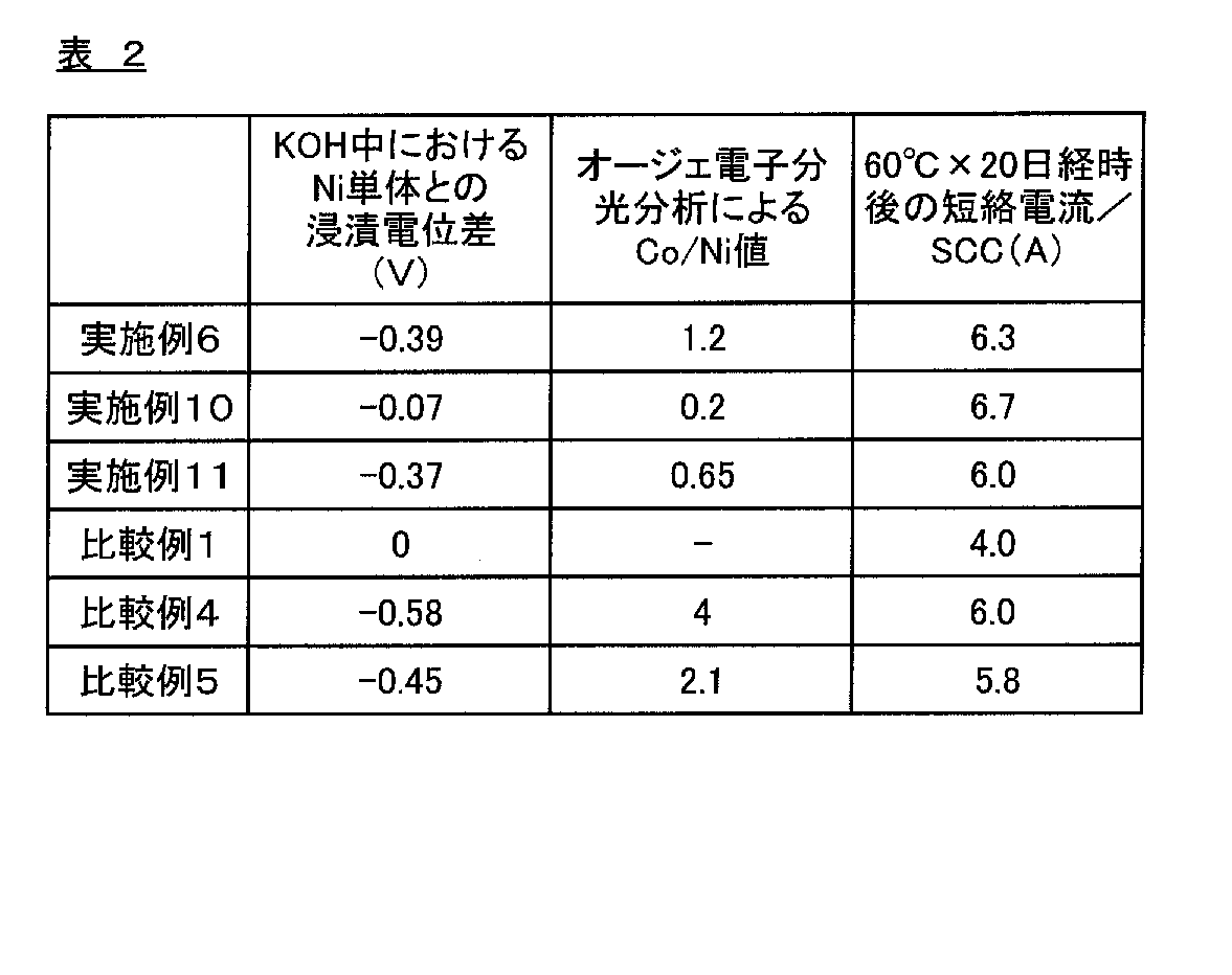
一方、ニッケル-コバルト合金層を最表面に形成しなかった比較例1,4、ニッケル-コバルト合金層の表面におけるオージェ電子分光分析によるCo/Ni値が1.5を超える比較例2~3,5においては、水酸化カリウム中に浸漬した際のコバルトの残存率が20%以下と低く、また、電池中におけるガス発生量が多くなる結果となった。
Claims (6)
- 電池容器内面となる面の最表面に、ニッケル-コバルト合金層が形成されてなる電池容器用表面処理鋼板であって、前記ニッケル-コバルト合金層の表面におけるオージェ電子分光分析によるCo/Ni値が0.1~1.5の範囲であることを特徴とする電池容器用表面処理鋼板。
- 前記ニッケル-コバルト合金層の水酸化カリウム水溶液中における、60℃での浸漬電位が、ニッケル単体の水酸化カリウム水溶液中における、60℃での浸漬電位に対して、-0.4~-0.02Vの範囲であることを特徴とする請求項1に記載の電池容器用表面処理鋼板。
- 前記ニッケル-コバルト合金層の下層として、ニッケル層を有することを特徴とする請求項1または2に記載の電池容器用表面処理鋼板。
- 前記ニッケル-コバルト合金層と鋼板との間に鉄-ニッケル拡散層および/または鉄-ニッケル-コバルト拡散層を有することを特徴とする請求項1~3のいずれかに記載の電池容器用表面処理鋼板。
- 請求項1~4のいずれかに記載の電池容器用表面処理鋼板を成形加工してなる電池容器。
- 請求項5に記載の電池容器を用いてなる電池。
Priority Applications (5)
| Application Number | Priority Date | Filing Date | Title |
|---|---|---|---|
| CN201280027900.4A CN103597626B (zh) | 2011-04-28 | 2012-04-26 | 电池容器用表面处理钢板、电池容器及电池 |
| KR1020137030961A KR101826919B1 (ko) | 2011-04-28 | 2012-04-26 | 전지 용기용 표면 처리 강판, 전지 용기 및 전지 |
| JP2013512425A JP5984800B2 (ja) | 2011-04-28 | 2012-04-26 | 電池容器用表面処理鋼板、電池容器および電池 |
| US14/114,479 US11223069B2 (en) | 2011-04-28 | 2012-04-26 | Surface-treated steel sheet for battery cases, battery case and battery |
| EP12777248.1A EP2704228B1 (en) | 2011-04-28 | 2012-04-26 | Surface-treated steel sheet for battery cases, battery case, and battery |
Applications Claiming Priority (2)
| Application Number | Priority Date | Filing Date | Title |
|---|---|---|---|
| JP2011-100538 | 2011-04-28 | ||
| JP2011100538 | 2011-04-28 |
Publications (1)
| Publication Number | Publication Date |
|---|---|
| WO2012147843A1 true WO2012147843A1 (ja) | 2012-11-01 |
Family
ID=47072358
Family Applications (1)
| Application Number | Title | Priority Date | Filing Date |
|---|---|---|---|
| PCT/JP2012/061192 Ceased WO2012147843A1 (ja) | 2011-04-28 | 2012-04-26 | 電池容器用表面処理鋼板、電池容器および電池 |
Country Status (6)
| Country | Link |
|---|---|
| US (1) | US11223069B2 (ja) |
| EP (1) | EP2704228B1 (ja) |
| JP (2) | JP5984800B2 (ja) |
| KR (1) | KR101826919B1 (ja) |
| CN (1) | CN103597626B (ja) |
| WO (1) | WO2012147843A1 (ja) |
Cited By (16)
| Publication number | Priority date | Publication date | Assignee | Title |
|---|---|---|---|---|
| WO2016148084A1 (ja) * | 2015-03-13 | 2016-09-22 | 東洋鋼鈑株式会社 | 電池容器用表面処理鋼板の製造方法、及び電池容器用表面処理鋼板 |
| WO2018159760A1 (ja) | 2017-03-02 | 2018-09-07 | 新日鐵住金株式会社 | 表面処理鋼板 |
| WO2018181950A1 (ja) * | 2017-03-31 | 2018-10-04 | 東洋鋼鈑株式会社 | 表面処理金属板、電池容器および電池 |
| JP2019517095A (ja) * | 2016-03-07 | 2019-06-20 | タタ、スティール、ユーケー、リミテッドTata Steel Uk Limited | 電池ケース用の鋼板の製造方法、およびその方法により製造される電池ケース |
| WO2019159794A1 (ja) | 2018-02-14 | 2019-08-22 | 日本製鉄株式会社 | 電池容器用表面処理鋼板及び電池容器用表面処理鋼板の製造方法 |
| WO2020009212A1 (ja) | 2018-07-06 | 2020-01-09 | 日本製鉄株式会社 | 表面処理鋼板および表面処理鋼板の製造方法 |
| WO2020009213A1 (ja) | 2018-07-06 | 2020-01-09 | 日本製鉄株式会社 | 表面処理鋼板および表面処理鋼板の製造方法 |
| KR20200080257A (ko) | 2017-10-27 | 2020-07-06 | 도요 고한 가부시키가이샤 | 표면 처리 강판 및 그 제조 방법 |
| DE112020002146T5 (de) | 2019-04-27 | 2022-01-05 | Toyo Kohan Co., Ltd. | Oberflächenbehandeltes stahlblech und verfahren zu seiner herstellung |
| JP7060187B1 (ja) * | 2020-12-03 | 2022-04-26 | 日本製鉄株式会社 | 表面処理鋼板 |
| WO2022118770A1 (ja) | 2020-12-03 | 2022-06-09 | 日本製鉄株式会社 | 表面処理鋼板 |
| WO2022118768A1 (ja) | 2020-12-03 | 2022-06-09 | 日本製鉄株式会社 | 表面処理鋼板 |
| WO2022118769A1 (ja) | 2020-12-03 | 2022-06-09 | 日本製鉄株式会社 | 表面処理鋼板 |
| WO2022215642A1 (ja) | 2021-04-09 | 2022-10-13 | 日本製鉄株式会社 | 表面処理鋼板 |
| KR20230113591A (ko) | 2020-12-03 | 2023-07-31 | 닛폰세이테츠 가부시키가이샤 | 표면 처리 강판 |
| KR20230113603A (ko) | 2020-12-03 | 2023-07-31 | 닛폰세이테츠 가부시키가이샤 | 표면 처리 강판 |
Families Citing this family (2)
| Publication number | Priority date | Publication date | Assignee | Title |
|---|---|---|---|---|
| KR20230078836A (ko) | 2015-12-03 | 2023-06-02 | 도요 고한 가부시키가이샤 | 전지 용기용 표면 처리 강판 |
| KR102148077B1 (ko) * | 2017-09-08 | 2020-08-26 | 주식회사 엘지화학 | 고체산화물 연료 전지용 연결재, 그 제조방법 및 고체 산화물 연료 전지 |
Citations (5)
| Publication number | Priority date | Publication date | Assignee | Title |
|---|---|---|---|---|
| WO1997042667A1 (fr) * | 1996-05-09 | 1997-11-13 | Toyo Kohan Co., Ltd. | Bac de batterie et tole d'acier traitee en surface pour bac de batterie |
| JPH09306439A (ja) * | 1996-05-21 | 1997-11-28 | Katayama Tokushu Kogyo Kk | 電池缶形成材料、電池缶形成方法および電池缶 |
| JP2003017010A (ja) * | 2001-06-29 | 2003-01-17 | Toshiba Battery Co Ltd | アルカリ乾電池 |
| JP2007122940A (ja) * | 2005-10-26 | 2007-05-17 | Toyo Kohan Co Ltd | 電池容器の製造方法、その電池容器の製造方法により製造した電池容器およびその電池容器を用いた電池 |
| JP2012048958A (ja) * | 2010-08-26 | 2012-03-08 | Fdk Energy Co Ltd | アルカリ電池 |
Family Cites Families (10)
| Publication number | Priority date | Publication date | Assignee | Title |
|---|---|---|---|---|
| MY133028A (en) * | 1997-07-08 | 2007-10-31 | Toyo Kohan Co Ltd | A surface-treated steel sheet for battery container, a battery container and a battery using same. |
| KR100696929B1 (ko) * | 2002-04-22 | 2007-03-20 | 도요 고한 가부시키가이샤 | 전지 케이스용 표면 처리 강판, 전지 케이스 및 그것을사용한 전지 |
| EP1667250A4 (en) * | 2003-08-13 | 2007-04-25 | Toyo Kohan Co Ltd | SURFACE-TREATED STEEL PLATE FOR BATTERY CAPSULE USE, BATTERY CAPSULATION AND BATTERY THEREWITH |
| JPWO2005056885A1 (ja) * | 2003-12-08 | 2007-07-05 | 東洋鋼鈑株式会社 | 電池容器用めっき鋼板、その電池容器用めっき鋼板を用いた電池容器、およびその電池容器を用いた電池 |
| JP5127444B2 (ja) * | 2004-03-25 | 2013-01-23 | ポスコ | 高強度焼付硬化型冷間圧延鋼板、溶融めっき鋼板及びその製造方法 |
| JP4748665B2 (ja) | 2005-02-18 | 2011-08-17 | 東洋鋼鈑株式会社 | 電池容器用めっき鋼板、その電池容器用めっき鋼板を用いた電池容器およびその電池容器を用いた電池 |
| JP5102945B2 (ja) | 2005-06-17 | 2012-12-19 | 東洋鋼鈑株式会社 | 電池容器用めっき鋼板、その電池容器用めっき鋼板を用いた電池容器およびその電池容器を用いたアルカリ電池 |
| JP2006348362A (ja) * | 2005-06-17 | 2006-12-28 | Toyo Kohan Co Ltd | 電池容器用めっき鋼板、その電池容器用めっき鋼板を用いた電池容器およびその電池容器を用いた電池 |
| JP2007035650A (ja) * | 2006-10-02 | 2007-02-08 | Toshiba Battery Co Ltd | 電池容器の溶接方法 |
| JP5172292B2 (ja) | 2007-11-22 | 2013-03-27 | Fdkエナジー株式会社 | アルカリ電池及びその製造方法 |
-
2012
- 2012-04-26 KR KR1020137030961A patent/KR101826919B1/ko active Active
- 2012-04-26 WO PCT/JP2012/061192 patent/WO2012147843A1/ja not_active Ceased
- 2012-04-26 JP JP2013512425A patent/JP5984800B2/ja active Active
- 2012-04-26 US US14/114,479 patent/US11223069B2/en active Active
- 2012-04-26 EP EP12777248.1A patent/EP2704228B1/en active Active
- 2012-04-26 CN CN201280027900.4A patent/CN103597626B/zh active Active
-
2016
- 2016-08-02 JP JP2016151708A patent/JP6152455B2/ja active Active
Patent Citations (5)
| Publication number | Priority date | Publication date | Assignee | Title |
|---|---|---|---|---|
| WO1997042667A1 (fr) * | 1996-05-09 | 1997-11-13 | Toyo Kohan Co., Ltd. | Bac de batterie et tole d'acier traitee en surface pour bac de batterie |
| JPH09306439A (ja) * | 1996-05-21 | 1997-11-28 | Katayama Tokushu Kogyo Kk | 電池缶形成材料、電池缶形成方法および電池缶 |
| JP2003017010A (ja) * | 2001-06-29 | 2003-01-17 | Toshiba Battery Co Ltd | アルカリ乾電池 |
| JP2007122940A (ja) * | 2005-10-26 | 2007-05-17 | Toyo Kohan Co Ltd | 電池容器の製造方法、その電池容器の製造方法により製造した電池容器およびその電池容器を用いた電池 |
| JP2012048958A (ja) * | 2010-08-26 | 2012-03-08 | Fdk Energy Co Ltd | アルカリ電池 |
Non-Patent Citations (1)
| Title |
|---|
| See also references of EP2704228A4 * |
Cited By (46)
| Publication number | Priority date | Publication date | Assignee | Title |
|---|---|---|---|---|
| WO2016148084A1 (ja) * | 2015-03-13 | 2016-09-22 | 東洋鋼鈑株式会社 | 電池容器用表面処理鋼板の製造方法、及び電池容器用表面処理鋼板 |
| KR20170128343A (ko) * | 2015-03-13 | 2017-11-22 | 도요 고한 가부시키가이샤 | 전지 용기용 표면 처리 강판의 제조 방법 및 전지 용기용 표면 처리 강판 |
| JPWO2016148084A1 (ja) * | 2015-03-13 | 2018-02-01 | 東洋鋼鈑株式会社 | 電池容器用表面処理鋼板の製造方法、及び電池容器用表面処理鋼板 |
| US10910607B2 (en) | 2015-03-13 | 2021-02-02 | Toyo Kohan Co., Ltd. | Method for producing surface-treated steel sheet for battery containers and surface-treated steel sheet for battery containers |
| KR102513977B1 (ko) | 2015-03-13 | 2023-03-23 | 도요 고한 가부시키가이샤 | 전지 용기용 표면 처리 강판의 제조 방법 및 전지 용기용 표면 처리 강판 |
| JP2019517095A (ja) * | 2016-03-07 | 2019-06-20 | タタ、スティール、ユーケー、リミテッドTata Steel Uk Limited | 電池ケース用の鋼板の製造方法、およびその方法により製造される電池ケース |
| JP7053483B2 (ja) | 2016-03-07 | 2022-04-12 | タタ、スティール、ユーケー、リミテッド | 電池ケース用の鋼板の製造方法、およびその方法により製造される電池ケース |
| WO2018159760A1 (ja) | 2017-03-02 | 2018-09-07 | 新日鐵住金株式会社 | 表面処理鋼板 |
| US11084252B2 (en) | 2017-03-02 | 2021-08-10 | Nippon Steel Corporation | Surface-treated steel sheet |
| KR20190112080A (ko) | 2017-03-02 | 2019-10-02 | 닛폰세이테츠 가부시키가이샤 | 표면 처리 강판 |
| KR20190132482A (ko) | 2017-03-31 | 2019-11-27 | 도요 고한 가부시키가이샤 | 표면 처리 금속판, 전지 용기 및 전지 |
| US11242591B2 (en) | 2017-03-31 | 2022-02-08 | Toyo Kohan Co., Ltd. | Surface-treated metal plate, cell container, and cell |
| JPWO2018181950A1 (ja) * | 2017-03-31 | 2020-02-06 | 東洋鋼鈑株式会社 | 表面処理金属板、電池容器および電池 |
| JP7041670B2 (ja) | 2017-03-31 | 2022-03-24 | 東洋鋼鈑株式会社 | 表面処理金属板、電池容器および電池 |
| DE112018001705T5 (de) | 2017-03-31 | 2019-12-19 | Toyo Kohan Co., Ltd. | Oberflächenbehandelte metallplatte, zellenbehälter und zelle |
| WO2018181950A1 (ja) * | 2017-03-31 | 2018-10-04 | 東洋鋼鈑株式会社 | 表面処理金属板、電池容器および電池 |
| US12270109B2 (en) | 2017-10-27 | 2025-04-08 | Toyo Kohan Co., Ltd. | Surface-treated steel sheet and method for manufacturing the same |
| KR20200080257A (ko) | 2017-10-27 | 2020-07-06 | 도요 고한 가부시키가이샤 | 표면 처리 강판 및 그 제조 방법 |
| KR20200111805A (ko) | 2018-02-14 | 2020-09-29 | 닛폰세이테츠 가부시키가이샤 | 전지 용기용 표면 처리 강판 및 전지 용기용 표면 처리 강판의 제조 방법 |
| US11713513B2 (en) | 2018-02-14 | 2023-08-01 | Nippon Steel Corporation | Surface-treated steel sheet for battery containers and manufacturing method of surface-treated steel sheet for battery containers |
| JPWO2019159794A1 (ja) * | 2018-02-14 | 2020-05-28 | 日本製鉄株式会社 | 電池容器用表面処理鋼板及び電池容器用表面処理鋼板の製造方法 |
| WO2019159794A1 (ja) | 2018-02-14 | 2019-08-22 | 日本製鉄株式会社 | 電池容器用表面処理鋼板及び電池容器用表面処理鋼板の製造方法 |
| WO2020009213A1 (ja) | 2018-07-06 | 2020-01-09 | 日本製鉄株式会社 | 表面処理鋼板および表面処理鋼板の製造方法 |
| JPWO2020009212A1 (ja) * | 2018-07-06 | 2020-07-09 | 日本製鉄株式会社 | 表面処理鋼板および表面処理鋼板の製造方法 |
| WO2020009212A1 (ja) | 2018-07-06 | 2020-01-09 | 日本製鉄株式会社 | 表面処理鋼板および表面処理鋼板の製造方法 |
| KR20210019524A (ko) | 2018-07-06 | 2021-02-22 | 닛폰세이테츠 가부시키가이샤 | 표면 처리 강판 및 표면 처리 강판의 제조 방법 |
| KR20210016462A (ko) | 2018-07-06 | 2021-02-15 | 닛폰세이테츠 가부시키가이샤 | 표면 처리 강판 및 표면 처리 강판의 제조 방법 |
| US11794449B2 (en) | 2018-07-06 | 2023-10-24 | Nippon Steel Corporation | Surface-treated steel sheet and method for manufacturing surface-treated steel sheet |
| US11352682B2 (en) | 2018-07-06 | 2022-06-07 | Nippon Steel Corporation | Surface-treated steel sheet and method for manufacturing surface-treated steel sheet |
| JPWO2020009213A1 (ja) * | 2018-07-06 | 2020-07-09 | 日本製鉄株式会社 | 表面処理鋼板および表面処理鋼板の製造方法 |
| KR20220004672A (ko) | 2019-04-27 | 2022-01-11 | 도요 고한 가부시키가이샤 | 표면 처리 강판 및 그 제조 방법 |
| US12448697B2 (en) | 2019-04-27 | 2025-10-21 | Toyo Kohan Co., Ltd. | Surface-treated steel sheet and production method therefor |
| DE112020002146T5 (de) | 2019-04-27 | 2022-01-05 | Toyo Kohan Co., Ltd. | Oberflächenbehandeltes stahlblech und verfahren zu seiner herstellung |
| JP7060187B1 (ja) * | 2020-12-03 | 2022-04-26 | 日本製鉄株式会社 | 表面処理鋼板 |
| KR20230113591A (ko) | 2020-12-03 | 2023-07-31 | 닛폰세이테츠 가부시키가이샤 | 표면 처리 강판 |
| KR20230113603A (ko) | 2020-12-03 | 2023-07-31 | 닛폰세이테츠 가부시키가이샤 | 표면 처리 강판 |
| KR20230113602A (ko) | 2020-12-03 | 2023-07-31 | 닛폰세이테츠 가부시키가이샤 | 표면 처리 강판 |
| WO2022118770A1 (ja) | 2020-12-03 | 2022-06-09 | 日本製鉄株式会社 | 表面処理鋼板 |
| WO2022118768A1 (ja) | 2020-12-03 | 2022-06-09 | 日本製鉄株式会社 | 表面処理鋼板 |
| US12129568B2 (en) | 2020-12-03 | 2024-10-29 | Nippon Steel Corporation | Surface-treated steel sheet |
| US12187009B2 (en) | 2020-12-03 | 2025-01-07 | Nippon Steel Corporation | Surface-treated steel sheet |
| US12252802B2 (en) | 2020-12-03 | 2025-03-18 | Nippon Steel Corporation | Surface-treated steel sheet |
| KR102828831B1 (ko) | 2020-12-03 | 2025-07-04 | 닛폰세이테츠 가부시키가이샤 | 표면 처리 강판 |
| WO2022118769A1 (ja) | 2020-12-03 | 2022-06-09 | 日本製鉄株式会社 | 表面処理鋼板 |
| KR20230165327A (ko) | 2021-04-09 | 2023-12-05 | 닛폰세이테츠 가부시키가이샤 | 표면 처리 강판 |
| WO2022215642A1 (ja) | 2021-04-09 | 2022-10-13 | 日本製鉄株式会社 | 表面処理鋼板 |
Also Published As
| Publication number | Publication date |
|---|---|
| US20140050971A1 (en) | 2014-02-20 |
| JPWO2012147843A1 (ja) | 2014-07-28 |
| EP2704228A1 (en) | 2014-03-05 |
| CN103597626A (zh) | 2014-02-19 |
| JP5984800B2 (ja) | 2016-09-06 |
| JP6152455B2 (ja) | 2017-06-21 |
| US11223069B2 (en) | 2022-01-11 |
| EP2704228A4 (en) | 2014-10-15 |
| KR101826919B1 (ko) | 2018-02-07 |
| JP2016186950A (ja) | 2016-10-27 |
| KR20140033058A (ko) | 2014-03-17 |
| CN103597626B (zh) | 2017-11-24 |
| EP2704228B1 (en) | 2018-06-13 |
Similar Documents
| Publication | Publication Date | Title |
|---|---|---|
| JP6152455B2 (ja) | 電池容器用表面処理鋼板、電池容器および電池 | |
| JP7187469B2 (ja) | 表面処理鋼板およびその製造方法 | |
| JP6117099B2 (ja) | 電池容器用表面処理鋼板およびその製造方法、電池容器および電池 | |
| JP7041670B2 (ja) | 表面処理金属板、電池容器および電池 | |
| CN113748225B (zh) | 表面处理钢板和其制造方法 | |
| US9887396B2 (en) | Surface-treated steel sheet for battery containers, battery container, and battery | |
| JP6200719B2 (ja) | 電池容器用表面処理鋼板の製造方法 | |
| JP6033304B2 (ja) | 電池容器用表面処理鋼板、電池容器および電池 | |
| WO2014007025A1 (ja) | 電池容器用表面処理鋼板およびその製造方法、電池容器および電池 | |
| JP2006093096A (ja) | 電池容器用めっき鋼板、その電池容器用めっき鋼板を用いた電池容器およびその電池容器を用いた電池 | |
| JP2007059087A (ja) | 電池容器用めっき鋼板、その電池容器用めっき鋼板を用いた電池容器およびその電池容器を用いた電池 |
Legal Events
| Date | Code | Title | Description |
|---|---|---|---|
| 121 | Ep: the epo has been informed by wipo that ep was designated in this application |
Ref document number: 12777248 Country of ref document: EP Kind code of ref document: A1 |
|
| ENP | Entry into the national phase |
Ref document number: 2013512425 Country of ref document: JP Kind code of ref document: A |
|
| NENP | Non-entry into the national phase |
Ref country code: DE |
|
| WWE | Wipo information: entry into national phase |
Ref document number: 14114479 Country of ref document: US |
|
| WWE | Wipo information: entry into national phase |
Ref document number: 2012777248 Country of ref document: EP |
|
| ENP | Entry into the national phase |
Ref document number: 20137030961 Country of ref document: KR Kind code of ref document: A |