WO2012147875A1 - ディスクブレーキ装置 - Google Patents
ディスクブレーキ装置 Download PDFInfo
- Publication number
- WO2012147875A1 WO2012147875A1 PCT/JP2012/061267 JP2012061267W WO2012147875A1 WO 2012147875 A1 WO2012147875 A1 WO 2012147875A1 JP 2012061267 W JP2012061267 W JP 2012061267W WO 2012147875 A1 WO2012147875 A1 WO 2012147875A1
- Authority
- WO
- WIPO (PCT)
- Prior art keywords
- brake pad
- rotor
- pad
- brake device
- clamping
- Prior art date
- Legal status (The legal status is an assumption and is not a legal conclusion. Google has not performed a legal analysis and makes no representation as to the accuracy of the status listed.)
- Ceased
Links
Images


Classifications
-
- F—MECHANICAL ENGINEERING; LIGHTING; HEATING; WEAPONS; BLASTING
- F16—ENGINEERING ELEMENTS AND UNITS; GENERAL MEASURES FOR PRODUCING AND MAINTAINING EFFECTIVE FUNCTIONING OF MACHINES OR INSTALLATIONS; THERMAL INSULATION IN GENERAL
- F16D—COUPLINGS FOR TRANSMITTING ROTATION; CLUTCHES; BRAKES
- F16D65/00—Parts or details
- F16D65/02—Braking members; Mounting thereof
- F16D65/04—Bands, shoes or pads; Pivots or supporting members therefor
- F16D65/092—Bands, shoes or pads; Pivots or supporting members therefor for axially-engaging brakes, e.g. disc brakes
- F16D65/095—Pivots or supporting members therefor
- F16D65/097—Resilient means interposed between pads and supporting members or other brake parts
- F16D65/0972—Resilient means interposed between pads and supporting members or other brake parts transmitting brake reaction force, e.g. elements interposed between torque support plate and pad
-
- F—MECHANICAL ENGINEERING; LIGHTING; HEATING; WEAPONS; BLASTING
- F16—ENGINEERING ELEMENTS AND UNITS; GENERAL MEASURES FOR PRODUCING AND MAINTAINING EFFECTIVE FUNCTIONING OF MACHINES OR INSTALLATIONS; THERMAL INSULATION IN GENERAL
- F16D—COUPLINGS FOR TRANSMITTING ROTATION; CLUTCHES; BRAKES
- F16D65/00—Parts or details
- F16D65/02—Braking members; Mounting thereof
- F16D65/04—Bands, shoes or pads; Pivots or supporting members therefor
- F16D65/092—Bands, shoes or pads; Pivots or supporting members therefor for axially-engaging brakes, e.g. disc brakes
- F16D65/095—Pivots or supporting members therefor
- F16D65/097—Resilient means interposed between pads and supporting members or other brake parts
- F16D65/0973—Resilient means interposed between pads and supporting members or other brake parts not subjected to brake forces
- F16D65/0974—Resilient means interposed between pads and supporting members or other brake parts not subjected to brake forces acting on or in the vicinity of the pad rim in a direction substantially transverse to the brake disc axis
- F16D65/0977—Springs made from sheet metal
Definitions
- the present invention relates to a disc brake device, and more particularly to a technique relating to a brake pad holding form in the disc brake device.
- 20 and 21 are side sectional views showing a state of the rotor 1 and the brake pad 2 arranged on the inner side of the rotor 1 in the disc brake device.
- the brake pad 2 receives a force F due to the inclination of the rotor 1 and tilts to follow the inclination of the rotor 1 as shown in FIG.
- the brake pad 2 in the disc brake device is normally held by the ear portion 3 being clamped in the radial direction of the rotor 1 by a clip load T of a pad clip (not shown). For this reason, when the brake pad 2 is inclined, the contact portions 4 existing above and below the brake pad 2 (in the example shown in FIG. 21, the inner side and the outer side of the rotor 1 in the radial direction) interval is to be moved in the direction narrowed to D 0 from D.
- the brake pad 2 tilted by the rotor 1 is subjected to a force to return the posture in the clamped state to a stable state by the pad clip, and a rotational moment M1 acting in the direction opposite to the inclination of the rotor 1 is generated. Dragging occurs between the brake pad 2 and the rotor 1 that are returning to the original state by the action of the rotational moment M1, and this is a cause of an increase in drag resistance.
- Patent Document 1 The technique disclosed in Patent Document 1 is characterized in that the sandwiching portion 5 (end surface of the ear portion 3) of the brake pad 2 is formed in an arc shape as shown in FIG. With such a configuration, as shown in FIG. 23, even when the brake pad 2 is tilted, the contact portions 4 positioned above and below the brake pad 2 do not shift in the rotor axial direction. The stable holding state by the clip load T of the pad clip is maintained.
- the disc brake device has a configuration as disclosed in Patent Document 1 described above, it is considered that the sliding resistance caused by the inclination of the rotor 1 can surely be reduced.
- An object of the present invention is to provide a disc brake device capable of achieving the above.
- a disc brake device including a brake pad slidable in the axial direction of a rotor, wherein a clamping mechanism for clamping a clamping portion of the brake pad from a radial direction of the rotor is provided.
- a disc provided with a pair of contact portions on which the rotational moment is applied to the landing portion when the brake pad is in a vertical position and is opposed to the brake pad and is displaced in the axial direction of the rotor when the brake pad is tilted.
- a disc brake device having the configuration as described in (1) or (2) above, wherein the clamping portion is provided at an ear portion protruding from a pressure plate constituting the brake pad. apparatus.
- the ear portion is present at a position away from the lining attachment surface of the brake pad. For this reason, even if it is a case where the cross-sectional shape of an ear
- a rotational moment generated in a direction in which the brake pad tilts due to a clamping force by the clamping mechanism is Disc brake device that is offset by frictional force generated between the clamping mechanism and the clamping mechanism.
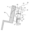
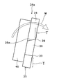
- FIG. 1 is a diagram showing a side configuration of a disc brake device when rotor runout / falling occurs according to an embodiment of the present invention.
- FIG. 2 is a diagram showing a side configuration of the disc brake device when the rotor run-out / tilt is settled according to the embodiment of the present invention.
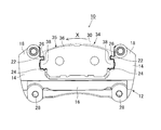
- FIG. 3 is a view showing a configuration of the inner side front of the disc brake device excluding the caliper according to the embodiment of the present invention.
- FIG. 4 is a perspective view of the disc brake device excluding the caliper according to the embodiment of the present invention.
- FIG. 5 is a diagram showing a front configuration of a support and a pad clip according to another example applicable to the embodiment of the present invention.
- FIG. 1 is a diagram showing a side configuration of a disc brake device when rotor runout / falling occurs according to an embodiment of the present invention.
- FIG. 2 is a diagram showing a side configuration of the disc brake device when the rotor run-out / tilt is settled according
- FIG. 6 is a diagram showing a plan configuration of a support and a pad clip according to another example applicable to the embodiment of the present invention.
- FIG. 7 is a perspective view showing a configuration of a support and a pad clip according to another example applicable to the embodiment of the present invention.
- FIG. 8 is a partially exploded perspective view of a support and pad clip according to another example applicable to the embodiment of the present invention.
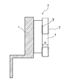
- FIG. 9 is a diagram illustrating the relationship between the rotor, the inner brake pad, and the load applied by the pad clip in a steady state.
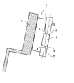
- FIG. 10 is a diagram showing the relationship between the rotor, the inner brake pad, the clip load T due to the pad clip, and the rotational moment M when the rotor swings or falls.
- FIG. 10 is a diagram showing the relationship between the rotor, the inner brake pad, the clip load T due to the pad clip, and the rotational moment M when the rotor swings or falls.
- FIG. 11 is a diagram for explaining the relationship between the holding state of the ear portion and the acting force.
- FIG. 12 is a diagram showing an example of a disc brake device in which the brake pad holding form is changed by changing the pad clip.
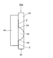
- FIG. 13 is a diagram illustrating an example in which the side cross-sectional shape of the ear portion of the brake pad is a half-ellipse.
- FIG. 14 is a diagram showing an example in which the side cross-sectional shape of the ear portion in the brake pad is a trapezoid and the constriction direction is changed.
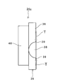
- FIG. 15 is a diagram showing an example in which the side cross-sectional shape of the ear portion of the brake pad is made into a half-ellipse shape and the formation direction of the arc portion is changed.
- FIG. 12 is a diagram showing an example of a disc brake device in which the brake pad holding form is changed by changing the pad clip.
- FIG. 13 is a diagram illustrating an example in which the side cross-sectional
- FIG. 16 is a diagram illustrating an example in which the side cross-sectional shape of the ear portion of the brake pad is a hexagon.
- FIG. 17 is a diagram showing an example in which the side cross-sectional shape of the ear portion in the brake pad is trapezoidal and the sandwiching portion located inside the rotor in the radial direction is parallel to the axial direction of the rotor.
- FIG. 18 is a diagram showing the relationship between the tilting direction of the brake pad shown in FIG. 17, the clamping force (clip load T) and the rotational moment M when tilting.
- FIG. 19 is a diagram illustrating an example of a brake pad clamping configuration using a pad clip when the brake pad has no ear.
- FIG. 20 is a side sectional view showing a state of a rotor in a conventional disc brake device and a brake pad arranged on the inner side of the rotor.
- FIG. 21 is a diagram showing the relationship between the tilting direction of the brake pad, the clamping force (clip load T), and the rotational moment M when tilting in the disc brake device shown in FIG.
- FIG. 22 is a side sectional view showing a state of a rotor and a brake pad disposed on the inner side of the rotor in another conventional disc brake device.
- FIG. 23 is a view showing the relationship between the tilting direction of the brake pad, the clamping force (clip load T), and the rotational moment M when tilting in the disc brake device shown in FIG.
- FIG. 1 is a diagram showing a side configuration of a disc brake device when rotor runout / tilt occurs.
- FIG. 2 is a diagram showing a side configuration of the disc brake device when the rotor run-out / falling is settled.
- FIG. 3 is a view showing the configuration of the inner side front of the disc brake device excluding the caliper.
- FIG. 4 is a perspective view of the disc brake device excluding the caliper.
- FIG. 9 is a diagram illustrating the relationship between the rotor, the inner brake pad, and the clip load T due to the pad clip in a steady state.
- FIG. 1 is a diagram showing a side configuration of a disc brake device when rotor runout / tilt occurs.
- FIG. 2 is a diagram showing a side configuration of the disc brake device when the rotor run-out / falling is settled.
- FIG. 3 is a view showing the configuration of the inner side front of the disc brake device excluding the caliper.
- FIG. 4 is a
- the disc brake device 10 is a diagram showing the relationship between the rotor, the inner brake pad, the clip load T due to the pad clip, and the rotational moment M when the rotor swings or falls.
- the disc brake device 10 according to the present embodiment has a support 12, a rotor 30, brake pads 32 and 34, and a caliper 42 as a basic configuration.
- the support 12 of the disc brake device 10 includes a torque receiving portion 14, an inner side frame 16, an outer side frame 20, and a support bridge 18 as main components.
- the torque receiving portion 14 is provided so as to form a pair on the turn-in side and the turn-out side of the rotor 30 on the inner side and the outer side of the rotor 30 rotating in the arrow X direction in FIG. Thus, it plays a role of receiving the rotational force (braking torque) of the brake pads 32 and 34 that are about to be supplied to the rotor 30.
- the torque receiving portion 14 according to the present embodiment has a convex portion 22 and a concave portion 24 on a surface facing a brake pad 32, 34, which will be described in detail later.
- the recess 24 is provided with a pad clip 26 for sandwiching and holding the brake pads 32 and 34 and improving the slidability of the brake pads 32 and 34 in the rotor axial direction.
- the pad clip 26 is fixed by clamping the convex portion 22 in the torque receiving portion 14, and has a clamping force (clip load T) that holds the brake pads 32 and 34 so as to be pulled up to the upper side of the concave portion 24. It is a pinching mechanism to be generated.
- the inner side frame 16 is a frame that connects the torque receiving portions 14 that are located on the inner side of the rotor 30 and on the turning-in side and the turning-out side of the rotor 30.
- the inner side frame 16 is provided with a female screw hole 28 intended for attachment to a vehicle (not shown).
- the outer side frame 20 is a frame that connects the torque receiving portions 14 that are located on the outer side of the rotor 30 and on the return side and the return side of the rotor 30.
- the support bridge 18 is a part connecting the torque receiving part 14 located on the inner side and the torque receiving part 14 located on the outer side across the rotor 30.
- FIG. 5 is a front view showing a configuration of a support and a pad clip according to another example in a state where the brake pad is assembled.
- FIG. 6 is a plan view (top view)
- FIG. 7 is a perspective view
- FIG. 8 is a partially exploded perspective view showing an assembly portion of a brake pad, a pad clip, and a support.
- a characteristic difference between the support 12 and the pad clip 26 of the embodiment according to another example shown in FIGS. 5 to 8 and the support 12 and the pad clip 26 of the above-described embodiment is that the torque receiving portion 14 of the support 12 is.
- the convex portion 22 of the support 12 is provided with a circular concave portion 22a on the upper surface thereof.
- a nail 27 that fits into the concave portion 22a formed on the upper surface when the convex portion 22 is clamped is formed in the clamping portion of the pad clip 26.
- the brake pads 32 and 34 include an outer brake pad 32 disposed on the outer side of the rotor 30 and an inner brake pad 34 disposed on the inner side of the rotor 30.
- the configuration is the same for all. Therefore, when referred to as a brake pad in the following description, the brake pad 34 on the inner side is indicated unless otherwise specified.
- the brake pad 34 is basically composed of a pressure plate 35 and a lining 40 that is a friction member attached to the pressure plate 35.
- the pressure plate 35 according to this embodiment is a plate body to which the lining 40 is attached. 36 (a portion excluding the ear portion 38 in the pressure plate 35) and an ear portion 38 that is provided on the return side and the return side of the rotor 30 with the plate body 36 as a reference.
- the ear portion 38 has inclined surfaces 38 a on the sides located on the inner side and the outer side in the radial direction of the rotor 30, which is a sandwiched portion by the pad clip 26.
- the trapezoid is provided.
- the inclined surface 38a is usually sandwiched between the main surface on the lining attachment surface side and the main surface on the opposite side from the main surface on the lining attachment surface side to the sandwiching portion having a surface formed parallel to the axial direction of the rotor 30. It is formed so that the distance between the wearing parts becomes narrow. By adopting such a configuration, only the widest straight line (contact portion 39) between the inclined surfaces 38a comes into contact with the pad clip 26 in the sandwiched portion.
- the inclination angle ⁇ 0 of the inclined surface 38 a is preferably larger than the inclination angle ⁇ 1 assumed for the brake pad 34.
- a frictional force that is a force in a direction that prevents the rotational moment M is generated.
- F 0 ⁇ d is converted to F 0 tan ⁇ 1 L for the rotational moment M
- the maximum friction for F 0 tan ⁇ 1 can be expressed as F 0 ⁇ .
- F 0 tan ⁇ 1 becomes larger than F 0 ⁇
- the rotational moment M becomes 0 or more, and the brake pad 34 may be excessively tilted, and dragging in the rotor radial direction may occur.
- F 0 and ⁇ 1 are adjusted so as to maintain the relationship of F 0 tan ⁇ 1 ⁇ F 0 ⁇ .
- the brake pads 34 it is possible to maintain the tilted state of the inclination angle theta 1.
- the rotational moment M generated when the brake pad is tilted is smaller than or equal to the sliding resistance F 1 between the ear 38 and the pad clip 26. Further, the clamping force (clip load T) with respect to the brake pad 34 is adjusted. With such a configuration, the posture of the brake pad 34 which is inclined by rocking or tilting of the rotor 30 can be held by the force of the sliding resistance F 1. Thereby, generation
- the side cross-sectional shape of the ear portion 38 of the pressure plate 35 is trapezoidal and the inclined surface 38a is provided so that the opposite side to the lining attachment surface is narrowed.
- the side cross-sectional shape of the ear portion 38 is a half-broken ellipse. Further, in the present embodiment, an elliptical arc portion having an arc surface is directed to the surface side opposite to the lining attachment surface, and coincides with the constriction direction of the ear portion 38 in the brake pad 34 in the above embodiment. . Even in the case where the side cross-sectional shape of the ear portion 38 is such, when the brake pad 34a is tilted due to the swinging or falling of the rotor 30, contact portions located on the inner side and the outer side in the radial direction of the rotor 30. 39 is shifted so as to be separated in the rotor axial direction. For this reason, similarly to the brake pad 34 according to the above-described embodiment, it is possible to obtain an effect of generating a rotational moment M in the same direction as the tilting direction when tilting.
- the brake pad 34b of the embodiment shown in FIG. 14 is the same as the brake pad 34 according to the above-described embodiment in that the side cross-sectional shape of the ear portion 38 is a trapezoid, but the inclination direction of the inclined surface 38a, that is, the constriction. Different directions. Specifically, the ear portion 38 is formed so that the distance between the inclined surfaces 38a becomes narrower from the surface opposite to the lining attachment surface toward the lining attachment surface, and is narrowed to the lining attachment surface side.
- the brake pads in the disc brake device are usually inserted into the support 12 (see FIG. 4) from the pressure plate 35 side to the lining 40 side for assembly. For this reason, the assembling property with respect to the support 12 provided with the pad clip 26 can be improved by making the constriction direction of the ear
- the side cross-sectional shape of the ear portion 38 is made into a half cracked oval shape like the brake pad 34a shown in FIG. It is set as the structure arrange
- the brake pad 34d of the embodiment shown in FIG. 16 has a hexagonal side cross-sectional shape of the ear portion 38, and the apex, that is, the contact portion 39 according to the embodiment, is located at the radially inner and outer facing positions of the rotor 30.
- the form is arranged.
- the side cross-sectional shape of the ear portion 38 in the pressure plate 35 is shown in FIG.
- the brake pad 34e of the embodiment shown in FIG. 17 is the same as the brake pad 34 according to the above-described embodiment in that the side cross-sectional shape of the ear portion 38 is a trapezoid, but is sandwiched between the rotor 30 in the radial direction.
- the inclined portion 38a is formed in parallel with the rotor axial direction, and has an inclined surface 38a having an inclination in which the width between the sandwiched portions widens in the opposite direction to the lining attached surface on the sandwiched portion located radially outward. Yes.
- the clamping portion positioned on the radially inner side of the rotor 30 has a clamping force ( Clip load T) is applied, and a clamping force (clip load T) is applied only to the contact portion 39 to the clamping portion located on the radially outer side of the rotor 30.
- the pad clips 26 and 26a both sandwich the ear 38 provided on the pressure plate 35 of the brake pad 34.
- the disc brake device according to the present embodiment only needs to have a pinching mechanism that uses the pinching force of the pad clip to generate a rotational moment in the same direction as the tilt direction of the brake pad. For this reason, even if the brake pad does not have an ear portion on the pressure plate 35, as shown in FIG. 19, the upper and lower sides of the brake pad 34f, that is, the radially inner side and the outer side of the rotor 30 in the brake pad 34f are After the sandwiching mode, the contact portion is provided by forming an inclined surface (an inclined surface conforming to the side sectional shape of the inclined surface 38a formed in the ear portion 38 in FIG. 9) on the sandwiched portion. good.
- this invention is not limited to embodiment mentioned above, A deformation
- the material, shape, dimension, numerical value, form, number, arrangement location, and the like of each component in the above-described embodiment are arbitrary and are not limited as long as the present invention can be achieved.
- This application is based on a Japanese patent application filed on April 26, 2011 (Japanese Patent Application No. 2011-098331), the contents of which are incorporated herein by reference.
- the disc brake device of the present invention when the brake pad is tilted by the swing of the rotor, it is possible to obtain a rotational moment in a direction in which the brake pad positively falls in the tilt input direction. As a result, it is possible to significantly reduce the sliding resistance when the brake pad is tilted.
Landscapes
- Engineering & Computer Science (AREA)
- General Engineering & Computer Science (AREA)
- Mechanical Engineering (AREA)
- Braking Arrangements (AREA)
Abstract
ディスクブレーキ装置10は、ブレーキパッド34における耳部38をロータ30の半径方向から挟着するパッドクリップ26が設けられ、耳部38には、ブレーキパッド34が垂直状態では対向位置に存在し、ブレーキパッド34が傾倒した際にはロータ30の軸方向にずれることにより、回転モーメントが働く一対の接触部39が設けられる。
Description
本発明は、ディスクブレーキ装置に係り、特にディスクブレーキ装置におけるブレーキパッドの保持形態に関する技術である。
昨今、環境問題や燃料高騰などの影響を受け、自動車や自動二輪車などには、走行距離に対する燃料消費量を低減した、いわゆる低燃費化の要請が高まっている。低燃費化の主体は現在、駆動系にガソリンエンジンと電動モータを用いたいわゆるハイブリッド化や、停車時のアイドリングストップ化、および軽量化などであるが、走行時における制動抵抗、すなわちブレーキにおける引き摺り抵抗も、燃費への影響があるとして注目を受けている。
このような背景を勘案し、上記引き摺り抵抗を低減すべく着目したのは、ロータの傾き(ロータ振れ・倒れ)に倣って配置形態を傾けるブレーキパッドによる抵抗である。図20及び図21は、ディスクブレーキ装置におけるロータ1と、ロータ1のインナ側に配置されたブレーキパッド2の様子を示す側断面図である。ロータ1に振れや倒れが生ずると、ブレーキパッド2は図21に示すように、ロータ1の傾きによる力Fを受け、ロータ1の傾きに倣うように傾く。
ディスクブレーキ装置におけるブレーキパッド2は通常、パッドクリップ(不図示)のクリップ荷重Tにより耳部3が、ロータ1の半径方向に挟着されることで保持されている。このため、ブレーキパッド2に傾きが生じた場合には、ブレーキパッド2の上下(図21に示す例では、耳部3におけるロータ1の半径方向内側と外側)に存在する接触部4は、その間隔がDからD0へと狭まる方向へ移動することとなる。
このため、ロータ1によって傾けられたブレーキパッド2には、パッドクリップにより挟持状態における姿勢が安定する状態に戻ろうとする力が働き、ロータ1の傾きと反対方向に作用する回転モーメントM1が生ずる。このような回転モーメントM1の働きにより元の状態に戻ろうとするブレーキパッド2とロータ1との間には、引き摺りが生ずることとなり、引き摺り抵抗増大の一因となっていた。
このような問題に対し、ブレーキパッド2がロータ振れ・倒れによる外力を受けた際、ブレーキパッド2の傾倒に必要とする力を低減すると共に傾倒した姿勢の保持を図り、これにより引き摺り抵抗を低減するといった技術が、特許文献1に開示されている。
特許文献1に開示されている技術は、図22に示すようにブレーキパッド2における挟着部5(耳部3の端面)を円弧状に形成するという点を特徴としたものである。このような構成とすることで、図23に示すように、ブレーキパッド2が傾いた場合であっても、ブレーキパッド2の上下に位置する接触部4は、互いにロータ軸方向にずれる事が無く、パッドクリップのクリップ荷重Tによる安定した挟持状態が保たれる。
上述した特許文献1に開示されているような構成を有するディスクブレーキ装置であれば、確かにロータ1の傾きによって生ずる摺動抵抗を低減することができると考えられる。しかし、上記特許文献1に開示されているディスクブレーキ装置ではブレーキパッド2が傾く際、その傾きが安定状態に至るまでロータ1の傾きに対する反力(=抵抗)を生じさせていることに変わりは無い。
本発明では、ロータの振れによってブレーキパッドに傾きが付与された際、ブレーキパッドが傾きの入力方向に積極的に倒れ込む方向の回転モーメントを得て、ブレーキパッド傾倒時における摺動抵抗の大幅な低減を図ることのできるディスクブレーキ装置を提供することを目的とする。
本発明の上記目的は、下記構成により達成することができる。
(1) ロータの軸方向に摺動可能なブレーキパッドを備えたディスクブレーキ装置であって、前記ブレーキパッドにおける挟着部を前記ロータの半径方向から挟着する挟着機構が設けられ、前記挟着部には、前記ブレーキパッドが垂直状態では対向位置に存在し、前記ブレーキパッドが傾倒した際には前記ロータの軸方向にずれることにより、回転モーメントが働く一対の接触部が設けられたディスクブレーキ装置。
(1) ロータの軸方向に摺動可能なブレーキパッドを備えたディスクブレーキ装置であって、前記ブレーキパッドにおける挟着部を前記ロータの半径方向から挟着する挟着機構が設けられ、前記挟着部には、前記ブレーキパッドが垂直状態では対向位置に存在し、前記ブレーキパッドが傾倒した際には前記ロータの軸方向にずれることにより、回転モーメントが働く一対の接触部が設けられたディスクブレーキ装置。
(2) 上記(1)のような構成を有するディスクブレーキ装置であって、前記接触部が、前記ロータの軸方向に平行に形成された面を持つ前記挟着部に、傾斜面または円弧面を設けることにより構成されたディスクブレーキ装置。
上記(2)のような構成とすることで、ブレーキパッドが傾倒した場合であっても挟着機構との接触点が接触部からずれることが無い。
上記(2)のような構成とすることで、ブレーキパッドが傾倒した場合であっても挟着機構との接触点が接触部からずれることが無い。
(3) 上記(1)または(2)のような構成を有するディスクブレーキ装置であって、前記挟着部が、前記ブレーキパッドを構成するプレッシャプレートに凸設された耳部に設けられるディスクブレーキ装置。
上記(3)のような構成とすることで、耳部は、ブレーキパッドにおけるライニング添着面から離れた位置に存在する。このため、耳部の断面形状を変更した場合であっても、制動時における押圧のバランスやプレッシャプレートの強度に影響を与えない。
上記(3)のような構成とすることで、耳部は、ブレーキパッドにおけるライニング添着面から離れた位置に存在する。このため、耳部の断面形状を変更した場合であっても、制動時における押圧のバランスやプレッシャプレートの強度に影響を与えない。
(4) 上記(1)または(2)のような構成を有するディスクブレーキ装置であって、前記挟着部が、前記ブレーキパッドを構成するプレッシャプレートにおける前記ロータの半径方向内側と外側であるディスクブレーキ装置。
上記(4)のような構成とすることで、耳部を備え無いブレーキパッドに対しても、適用することが可能となる。
上記(4)のような構成とすることで、耳部を備え無いブレーキパッドに対しても、適用することが可能となる。
(5) 上記(1)乃至(4)のいずれかの構成を有するディスクブレーキ装置であって、前記挟着機構による挟着力により前記ブレーキパッドが傾倒する方向に生ずる回転モーメントは、前記挟着部と前記挟着機構との間に生ずる摩擦力により相殺されるディスクブレーキ装置。
上記(5)のような構成とすることで、ロータの振れや倒れによるブレーキパッドに対する押し付け力が無くなった場合でも、ブレーキパッドは、傾いた状態を維持することができる。また、回転モーメントの作用によるブレーキパッドの傾き過多を抑制することができ、これによる摺動抵抗の増加も抑制することができる。
上記(5)のような構成とすることで、ロータの振れや倒れによるブレーキパッドに対する押し付け力が無くなった場合でも、ブレーキパッドは、傾いた状態を維持することができる。また、回転モーメントの作用によるブレーキパッドの傾き過多を抑制することができ、これによる摺動抵抗の増加も抑制することができる。
以下、本発明のディスクブレーキ装置に係る実施形態について、図面を参照しつつ詳細に説明する。図1はロータ振れ・倒れが生じた際のディスクブレーキ装置の側面構成を示す図である。図2はロータ振れ・倒れが収まった際のディスクブレーキ装置の側面構成を示す図である。図3は、キャリパを除くディスクブレーキ装置のインナ側正面の構成を示す図である。図4は、キャリパを除くディスクブレーキ装置の斜視図である。図9は、定常状態におけるロータとインナ側ブレーキパッドと、パッドクリップによるクリップ荷重Tの関係を示す図である。図10は、ロータ振れ・倒れが生じた際のロータとインナ側ブレーキパッドと、パッドクリップによるクリップ荷重T、および回転モーメントMの関係を示す図である。
本実施形態に係るディスクブレーキ装置10は、サポート12とロータ30、ブレーキパッド32,34、およびキャリパ42を基本構成とするものである。
本実施形態に係るディスクブレーキ装置10は、サポート12とロータ30、ブレーキパッド32,34、およびキャリパ42を基本構成とするものである。
本実施形態に係るディスクブレーキ装置10のサポート12は、トルク受け部14と、インナ側フレーム16、アウタ側フレーム20、およびサポートブリッジ18を主な構成要素としている。
トルク受け部14は、図3中矢印X方向に回転するロータ30のインナ側とアウタ側においてそれぞれ、ロータ30の回入側と回出側に対を成すように設けられ、制動時に生ずる摩擦力によってロータ30に供回りしようとするブレーキパッド32,34の回転力(制動トルク)を受け止める役割を担う。本実施形態に係るトルク受け部14は、詳細を後述するブレーキパッド32,34との対向面に凸部22、および凹部24を有する。凹部24には、ブレーキパッド32,34を挟着保持すると共に、ブレーキパッド32,34のロータ軸方向への摺動性を向上させるためのパッドクリップ26が設けられている。
本実施形態では、パッドクリップ26は、トルク受け部14における凸部22を挟持することで固定され、ブレーキパッド32,34を凹部24の上辺に引き上げるように保持する挟着力(クリップ荷重T)を生じさせる挟着機構とされている。
インナ側フレーム16は、ロータ30のインナ側であって、ロータ30の回入側と回出側に位置するトルク受け部14を連結するフレームである。なお、インナ側フレーム16には、図示しない車両への取り付けを目的とした雌ネジ孔28が設けられている。
アウタ側フレーム20は、ロータ30のアウタ側であって、ロータ30の回入側と回出側に位置するトルク受け部14を連結するフレームである。
サポートブリッジ18は、ロータ30を跨いでインナ側に位置するトルク受け部14とアウタ側に位置するトルク受け部14とを連結する部位である。
アウタ側フレーム20は、ロータ30のアウタ側であって、ロータ30の回入側と回出側に位置するトルク受け部14を連結するフレームである。
サポートブリッジ18は、ロータ30を跨いでインナ側に位置するトルク受け部14とアウタ側に位置するトルク受け部14とを連結する部位である。
ここで、上述したサポート12やパッドクリップ26の形態は、本発明を実施する上での一例に過ぎない。本実施形態に適用可能なサポートおよびパッドクリップの他の一例として、図5~図8に示すものを挙げることができる。なお、図5はブレーキパッドを組付けた状態の他の例に係るサポートおよびパッドクリップの構成を示す正面図である。また、図6は同平面(上面)図、図7は斜視図であり、図8はブレーキパッド、パッドクリップ、およびサポートの組付け部分を示す、部分分解斜視図である。
図5~図8に示す他の一例に係る実施形態のサポート12およびパッドクリップ26と、上述した実施形態のサポート12およびパッドクリップ26との特徴的な相違点は、サポート12におけるトルク受け部14を構成する凸部22の形態と、この凸部22を挟持するパッドクリップ26における挟持部の形態にある。具体的には、サポート12の凸部22には、その上面に円形状の凹部22aが設けられている。また、パッドクリップ26における挟持部には、凸部22を挟持した際に、上面に形成された凹部22aに嵌り込む爪27が形成されている。このような構成とすることで、トルク受け部14に組付けるパッドクリップ26の倒れ止めを図ることができる。
ブレーキパッド32,34は、本実施形態の場合、ロータ30のアウタ側に配置されるアウタ側ブレーキパッド32と、ロータ30のインナ側に配置されるインナ側ブレーキパッド34とが存在するが、その構成は、いずれも同様としている。よって、以下の説明においてブレーキパッドと称する場合、特別な指定が無い限りインナ側のブレーキパッド34を指すものとする。ブレーキパッド34は、プレッシャプレート35と、このプレッシャプレート35に添着された摩擦部材であるライニング40とを基本として構成される、本実施形態に係るプレッシャプレート35は、ライニング40が添着されるプレート本体36(プレッシャプレート35における耳部38を除いた部分)と、プレート本体36を基準としてロータ30の回入側と回出側に凸設された耳部38とを基本として構成されている。
本実施形態に係る耳部38は、側断面形状が図9及び図10に示すように、パッドクリップ26による挟着部であるロータ30の半径方向内側と外側に位置する辺に傾斜面38aを設けた台形状とされている。傾斜面38aは、通常、ロータ30の軸方向と平行に形成される面を持つ挟着部に、ライニング添着面側の主面から反対側の主面にかけて、半径方向内側と外側に位置する挟着部間の距離が狭くなるように形成されている。このような構成とすることにより、挟着部では、傾斜面38a間の最も広い部位の直線(接触部39)のみがパッドクリップ26と接触することとなる。また、打ち抜きにより形成されるプレッシャプレート35においては、このような傾斜形態では、打ち抜きダレが生ずる面と同じ側が窄む(狭くなる)こととなる。このため、1度の打ち抜き加工により形状形成が可能となるため、加工コストの高騰を招く虞が無い。
傾斜面38aの傾斜角度θ0は、ブレーキパッド34に対して想定される傾き角度θ1よりも大きい角度とすると良い。このような構成とすることで、ブレーキパッド34が傾倒した場合であっても、接触部39のみがパッドクリップ26と接触している状態を維持することができ、パッドクリップ26との接触点が接触部39からずれることが無い。これにより、ロータ振れ・倒れに起因してブレーキパッド34が傾倒した場合には、ロータ30の半径方向内側と外側に位置する接触部39がロータ30の軸方向に移動し、両者の間にシフト量Δdが生ずることとなる。
ここで、パッドクリップ26によるクリップ荷重TをF0(片側あたり1/2F0)とすると、耳部38には、F0Δdで示すことのできる回転モーメントMが生ずることとなる(図11参照)。このため、パッドクリップ26によって挟着力が付与された場合であっても、制動力解除時にブレーキパッド34が垂直状態に戻ろうとすることが無い。よって、ブレーキパッド34が垂直状態に戻ろうとする事に起因して生ずる引き摺り抵抗を低減することができる。
一方で、接触部39(本説明では、説明を簡単化するためにロータ半径方向外側の接触部39を指すこととする)では、回転モーメントMを妨げる方向の力である摩擦力が生ずる。回転モーメントMについて、F0ΔdをF0tanθ1Lと変換すると、F0tanθ1に対する最大摩擦はF0μと示すことができる。ここで、F0tanθ1がF0μよりも大きくなった場合には、回転モーメントMが0以上となり、ブレーキパッド34に余分な倒れ込みが発生し、ロータ半径方向内側の引き摺りが生じてしまう可能性がある。このため、本実施形態では、F0tanθ1≦F0μの関係を保つようにF0およびθ1を調整している。これにより、ブレーキパッド34は、傾斜角度θ1の傾き状態を維持することが可能となる。
このような観点からは、傾斜面38aの傾斜角度θ0は、F0tanθ1=F0μとなる傾き角度θ1と等しくしておくと良い。こうすることにより、傾倒過多によるブレーキパッド34の無用な倒れ込み(引き摺り)を防ぐことができるからである。
本実施形態に係るディスクブレーキ装置10におけるパッドクリップ26は、ブレーキパッド傾倒時に生ずる回転モーメントMが、耳部38とパッドクリップ26との間の摺動抵抗F1よりも小さく、あるいは同等となるように、ブレーキパッド34に対する挟着力(クリップ荷重T)が調整されている。このような構成とすることにより、ロータ30の振れや倒れによって傾けられたブレーキパッド34の姿勢を、摺動抵抗F1の力で保持することができる。これにより、ブレーキパッド34が過度に倒れ込むことによる引き摺り抵抗の発生を防ぐことができる。
なお、本実施形態に係るディスクブレーキ装置10では図3に示すように、ブレーキパッド34をパッドクリップ26で挟着する際、ブレーキパッド34をトルク受け部14の凹部24の上辺に押し上げるような形態を採る旨説明したが、図12に示すように凹部24の下側にブレーキパッド34を押し下げる形態で挟着保持するパッドクリップ26aを採用しても良い。このような構成とした場合であっても、上記実施形態と同様な効果を奏することができるからである。
また、上記実施形態に係るディスクブレーキ装置10では、プレッシャプレート35の耳部38の側断面形状を台形状とし、ライニング添着面と反対側が窄むように傾斜面38aを設ける旨説明した。しかしながら本実施形態に係るディスクブレーキ装置10では、図13~図17に示すような側断面形状の耳部38を備えたブレーキパッドを採用することもできる。
図13に示す実施形態のブレーキパッド34aは、耳部38の側断面形状を半割れの長円型としている。また、本実施形態では、円弧面を有する長円の円弧部分をライニング添着面と反対の面側に向けており、上記実施形態におけるブレーキパッド34における耳部38の窄み方向と一致させている。耳部38の側断面形状をこのようなものとした場合であっても、ロータ30の振れや倒れによってブレーキパッド34aが傾倒した場合には、ロータ30の半径方向内側と外側に位置する接触部39がロータ軸方向へ離間するようにシフトすることとなる。このため、上記実施形態に係るブレーキパッド34と同様に、傾倒時に傾倒方向と同一方向への回転モーメントMを生じさせるといった効果を得ることができる。
また、図14に示す実施形態のブレーキパッド34bは、耳部38の側断面形状を台形とする点で上記実施形態に係るブレーキパッド34と同様であるが、傾斜面38aの傾斜方向、すなわち窄みの方向を異ならせている。具体的には、ライニング添着面と反対側の面から、ライニング添着面へ向けて傾斜面38a間の距離が狭くなるように耳部38を形成し、ライニング添着面側に窄む形態としている。このような構成とした場合であっても、ブレーキパッド34bが傾倒する際には、ロータ30の半径方向内側と外側に位置する接触部39がロータ軸方向へ離間するようにシフトすることとなる。よって、上記実施形態に係るブレーキパッド34と同様な効果を奏することができる。また、ディスクブレーキ装置におけるブレーキパッドは通常、サポート12(図4参照)に対してプレッシャプレート35側からライニング40側へ挿入して組付けが成される。このため、本実施形態のように耳部38の窄み方向をライニング添着面側とすることで、パッドクリップ26を備えたサポート12に対する組付け性を向上させることができる。
また、図15に示す実施形態のブレーキパッド34cは、耳部38の側断面形状を図13に示すブレーキパッド34aと同様に、半割れの長円型とした上で、円弧部分をライニング添着面側に向けて配置する構成としている。このような形態であっても、上記実施形態に係るブレーキパッド34と同様な効果を奏することができる。
また、図16に示す実施形態のブレーキパッド34dは、耳部38の側断面形状を六角形とし、ロータ30の半径方向内側と外側の対向位置にそれぞれ頂点、すなわち実施形態に係る接触部39が配置される形態としている。このように、挟着部の一部を凸とするようにして、半径方向内側と外側の対向位置に接触部39を設けることでも、ブレーキパッド傾倒時に接触部39がロータ30の軸方向に離間するようにシフトするといった作用を得ることができる。よって、上記実施形態に係るブレーキパッド34と同様な効果を奏することができる。
さらに、ブレーキパッドの傾倒方向が一定方向である場合(例えばブレーキパッドにおける半径方向外側がインナ側へ傾倒すると予め解っている場合)には、プレッシャプレート35における耳部38の側断面形状を、図17に示すような実施形態としても良い。図17に示す実施形態のブレーキパッド34eは、耳部38の側断面形状を台形としている点で上記実施形態に係るブレーキパッド34と同様であるが、ロータ30の半径方向内側に位置する挟着部をロータ軸方向と平行に形成し、半径方向外側に位置する挟着部に、ライニング添着面と反対方向へ向けて挟着部間の幅が広がる傾きを持った傾斜面38aを持たせている。このような実施形態のブレーキパッド34eでは、ブレーキパッド34eに傾きが付与されていない状態においては、ロータ30の半径方向内側に位置する挟着部には、ロータ30の軸方向全体に挟着力(クリップ荷重T)が付与されることとなり、ロータ30の半径方向外側に位置する挟着部には、接触部39のみに挟着力(クリップ荷重T)が付与されることとなる。
一方、ブレーキパッド34eに傾斜が付与されると図18に示すように、挟着力(クリップ荷重T)はロータ30の半径方向外側に位置する接触部39と、半径方向内側におけるライニング添着面と反対側に位置する一点(線:接触部39)のみに付与されることとなり、上記実施形態に係るブレーキパッド34と同様な作用を得ることができる。
また、上記実施形態ではいずれも、パッドクリップ26,26aはブレーキパッド34のプレッシャプレート35に設けられた耳部38を挟着する旨記載した。しかしながら、本実施形態に係るディスクブレーキ装置は、パッドクリップによる挟着力を利用して、ブレーキパッドの傾倒方向と同一方向へ回転モーメントを生じさせる挟着機構を持てば良い。このため、プレッシャプレート35に耳部を持たないブレーキパッドであっても、図19に示すように、ブレーキパッド34fの上下、すなわちブレーキパッド34fにおけるロータ30の半径方向内側と外側をパッドクリップ26bにより挟着する形態とした上で、挟着部に傾斜面(図9における耳部38に形成した傾斜面38aの側断面形状に順ずる傾斜面)を形成して接触部を設けるようにすれば良い。
なお、本発明は、上述した実施形態に限定されるものではなく、適宜、変形、改良、等が可能である。その他、上述した実施形態における各構成要素の材質、形状、寸法、数値、形態、数、配置箇所、等は本発明を達成できるものであれば任意であり、限定されない。
また、本出願は、2011年4月26日出願の日本特許出願(特願2011-098331)に基づくものであり、その内容はここに参照として取り込まれる。
また、本出願は、2011年4月26日出願の日本特許出願(特願2011-098331)に基づくものであり、その内容はここに参照として取り込まれる。
本発明のディスクブレーキ装置によれば、ロータの振れによってブレーキパッドに傾きが付与された際、ブレーキパッドが傾きの入力方向に積極的倒れ込む方向の回転モーメントを得ることができる。これにより、ブレーキパッド傾倒時における摺動抵抗の大幅な低減を図ることが可能となる。
10………ディスクブレーキ装置、12………サポート、14………トルク受け部、16………インナ側フレーム、18………サポートブリッジ、20………アウタ側フレーム、22………凸部、24………凹部、26………パッドクリップ(挟着機構)、28………雌ネジ孔、30………ロータ、32………ブレーキパッド、34………ブレーキパッド、35………プレッシャプレート、36………プレート本体、38………耳部(挟着部)、38a………傾斜面、39………接触部、40………ライニング、42………キャリパ。
Claims (7)
- ロータの軸方向に摺動可能なブレーキパッドを備えたディスクブレーキ装置であって、
前記ブレーキパッドにおける挟着部を前記ロータの半径方向から挟着する挟着機構が設けられ、
前記挟着部には、前記ブレーキパッドが垂直状態では対向位置に存在し、前記ブレーキパッドが傾倒した際には前記ロータの軸方向にずれることにより、回転モーメントが働く一対の接触部が設けられたディスクブレーキ装置。 - 前記接触部が、前記ロータの軸方向に平行に形成された面を持つ前記挟着部に、傾斜面または円弧面を設けることにより構成された請求項1に記載のディスクブレーキ装置。
- 前記挟着部が、前記ブレーキパッドを構成するプレッシャプレートに凸設された耳部に設けられる請求項1または2に記載のディスクブレーキ装置。
- 前記挟着部が、前記ブレーキパッドを構成するプレッシャプレートにおける前記ロータの半径方向内側と外側である請求項1または2に記載のディスクブレーキ装置。
- 前記挟着機構による挟着力により前記ブレーキパッドが傾倒する方向に生ずる回転モーメントは、前記挟着部と前記挟着機構との間に生ずる摩擦力により相殺される請求項1または2に記載のディスクブレーキ装置。
- 前記挟着機構による挟着力により前記ブレーキパッドが傾倒する方向に生ずる回転モーメントは、前記挟着部と前記挟着機構との間に生ずる摩擦力により相殺される請求項3に記載のディスクブレーキ装置。
- 前記挟着機構による挟着力により前記ブレーキパッドが傾倒する方向に生ずる回転モーメントは、前記挟着部と前記挟着機構との間に生ずる摩擦力により相殺される請求項4に記載のディスクブレーキ装置。
Applications Claiming Priority (2)
| Application Number | Priority Date | Filing Date | Title |
|---|---|---|---|
| JP2011098331A JP5704536B2 (ja) | 2011-04-26 | 2011-04-26 | ディスクブレーキ装置 |
| JP2011-098331 | 2011-04-26 |
Publications (1)
| Publication Number | Publication Date |
|---|---|
| WO2012147875A1 true WO2012147875A1 (ja) | 2012-11-01 |
Family
ID=47072389
Family Applications (1)
| Application Number | Title | Priority Date | Filing Date |
|---|---|---|---|
| PCT/JP2012/061267 Ceased WO2012147875A1 (ja) | 2011-04-26 | 2012-04-26 | ディスクブレーキ装置 |
Country Status (2)
| Country | Link |
|---|---|
| JP (1) | JP5704536B2 (ja) |
| WO (1) | WO2012147875A1 (ja) |
Cited By (1)
| Publication number | Priority date | Publication date | Assignee | Title |
|---|---|---|---|---|
| DE102018005036A1 (de) * | 2018-06-25 | 2020-01-02 | Lucas Automotive Gmbh | Führungselement für eine Fahrzeugscheibenbremse |
Citations (6)
| Publication number | Priority date | Publication date | Assignee | Title |
|---|---|---|---|---|
| JPS57100634U (ja) * | 1980-12-12 | 1982-06-21 | ||
| JPH0669459U (ja) * | 1993-03-18 | 1994-09-30 | トキコ株式会社 | ディスクブレーキ |
| JPH0893807A (ja) * | 1994-09-28 | 1996-04-12 | Tokico Ltd | ディスクブレーキ |
| JPH08232991A (ja) * | 1995-02-28 | 1996-09-10 | Nissan Motor Co Ltd | ディスクブレーキ装置 |
| JP2006170251A (ja) * | 2004-12-13 | 2006-06-29 | Toyota Motor Corp | ディスクブレーキ |
| JP2008095816A (ja) * | 2006-10-11 | 2008-04-24 | Toyota Motor Corp | ディスクブレーキ装置 |
-
2011
- 2011-04-26 JP JP2011098331A patent/JP5704536B2/ja not_active Expired - Fee Related
-
2012
- 2012-04-26 WO PCT/JP2012/061267 patent/WO2012147875A1/ja not_active Ceased
Patent Citations (6)
| Publication number | Priority date | Publication date | Assignee | Title |
|---|---|---|---|---|
| JPS57100634U (ja) * | 1980-12-12 | 1982-06-21 | ||
| JPH0669459U (ja) * | 1993-03-18 | 1994-09-30 | トキコ株式会社 | ディスクブレーキ |
| JPH0893807A (ja) * | 1994-09-28 | 1996-04-12 | Tokico Ltd | ディスクブレーキ |
| JPH08232991A (ja) * | 1995-02-28 | 1996-09-10 | Nissan Motor Co Ltd | ディスクブレーキ装置 |
| JP2006170251A (ja) * | 2004-12-13 | 2006-06-29 | Toyota Motor Corp | ディスクブレーキ |
| JP2008095816A (ja) * | 2006-10-11 | 2008-04-24 | Toyota Motor Corp | ディスクブレーキ装置 |
Cited By (1)
| Publication number | Priority date | Publication date | Assignee | Title |
|---|---|---|---|---|
| DE102018005036A1 (de) * | 2018-06-25 | 2020-01-02 | Lucas Automotive Gmbh | Führungselement für eine Fahrzeugscheibenbremse |
Also Published As
| Publication number | Publication date |
|---|---|
| JP2012229751A (ja) | 2012-11-22 |
| JP5704536B2 (ja) | 2015-04-22 |
Similar Documents
| Publication | Publication Date | Title |
|---|---|---|
| US10724589B2 (en) | Brake pad retention system of a disc brake of a motor vehicle | |
| EP2873886B1 (en) | Disk brake | |
| JP5512337B2 (ja) | 鉄道車両用ブレーキライニング | |
| US10364855B2 (en) | Disc brake caliper | |
| KR102007684B1 (ko) | 드럼 브레이크 어셈블리용 브레이크 라이닝 | |
| CN103477110B (zh) | 摩擦片承载板 | |
| JP2011529162A (ja) | ブレーキキャリパー用パッド及びディスクブレーキ用ブレーキキャリパー | |
| JP2012251597A (ja) | 鉄道車両用ブレーキライニングおよびそれを備えたディスクブレーキ | |
| JP2004340214A (ja) | ディスクブレーキ装置 | |
| WO2013150881A1 (ja) | ディスクブレーキ用摩擦パッド組立て体 | |
| JP6567084B2 (ja) | 鉄道車両用ブレーキライニングおよびそれを備えたディスクブレーキ | |
| US20190154093A1 (en) | Friction pad assembly for disc brakes | |
| WO2013157337A1 (ja) | ディスクブレーキ用摩擦パッド組立て体 | |
| JP2013185707A (ja) | 自動車用ブレーキディスクの製作方法及びブレーキディスク | |
| CN103775526B (zh) | 用于机动车的摩擦离合器和相应的机动车 | |
| WO2013121731A1 (ja) | 鉄道車両用ブレーキライニングおよびそれを備えたディスクブレーキ | |
| JP6338346B2 (ja) | ディスクブレーキ用パッド及びディスクブレーキ装置 | |
| KR102150231B1 (ko) | 인벌류트 스퍼마운팅 디스크 | |
| CN103380310B (zh) | 衬块夹具的安装结构 | |
| WO2012147875A1 (ja) | ディスクブレーキ装置 | |
| US20180156287A1 (en) | Disc brake torque abutment structure | |
| CN103384776B (zh) | 盘形制动器装置 | |
| CN106104047B (zh) | 用于行程控制式的补偿调节装置的螺杆传动装置 | |
| JP2010048363A (ja) | ブレーキキャリパ | |
| US20190383339A1 (en) | Disc brake pad and disc brake device |
Legal Events
| Date | Code | Title | Description |
|---|---|---|---|
| 121 | Ep: the epo has been informed by wipo that ep was designated in this application |
Ref document number: 12776423 Country of ref document: EP Kind code of ref document: A1 |
|
| NENP | Non-entry into the national phase |
Ref country code: DE |
|
| 122 | Ep: pct application non-entry in european phase |
Ref document number: 12776423 Country of ref document: EP Kind code of ref document: A1 |