WO2012147957A1 - オートテンショナ - Google Patents
オートテンショナ Download PDFInfo
- Publication number
- WO2012147957A1 WO2012147957A1 PCT/JP2012/061467 JP2012061467W WO2012147957A1 WO 2012147957 A1 WO2012147957 A1 WO 2012147957A1 JP 2012061467 W JP2012061467 W JP 2012061467W WO 2012147957 A1 WO2012147957 A1 WO 2012147957A1
- Authority
- WO
- WIPO (PCT)
- Prior art keywords
- water
- cylindrical portion
- peripheral surface
- fixing member
- rotating member
- Prior art date
- Legal status (The legal status is an assumption and is not a legal conclusion. Google has not performed a legal analysis and makes no representation as to the accuracy of the status listed.)
- Ceased
Links
Images





Classifications
-
- F—MECHANICAL ENGINEERING; LIGHTING; HEATING; WEAPONS; BLASTING
- F16—ENGINEERING ELEMENTS AND UNITS; GENERAL MEASURES FOR PRODUCING AND MAINTAINING EFFECTIVE FUNCTIONING OF MACHINES OR INSTALLATIONS; THERMAL INSULATION IN GENERAL
- F16H—GEARING
- F16H7/00—Gearings for conveying rotary motion by endless flexible members
- F16H7/08—Means for varying tension of belts, ropes or chains
- F16H7/10—Means for varying tension of belts, ropes or chains by adjusting the axis of a pulley
-
- F—MECHANICAL ENGINEERING; LIGHTING; HEATING; WEAPONS; BLASTING
- F16—ENGINEERING ELEMENTS AND UNITS; GENERAL MEASURES FOR PRODUCING AND MAINTAINING EFFECTIVE FUNCTIONING OF MACHINES OR INSTALLATIONS; THERMAL INSULATION IN GENERAL
- F16H—GEARING
- F16H7/00—Gearings for conveying rotary motion by endless flexible members
- F16H7/08—Means for varying tension of belts, ropes or chains
- F16H7/10—Means for varying tension of belts, ropes or chains by adjusting the axis of a pulley
- F16H7/12—Means for varying tension of belts, ropes or chains by adjusting the axis of a pulley of an idle pulley
- F16H7/1209—Means for varying tension of belts, ropes or chains by adjusting the axis of a pulley of an idle pulley with vibration damping means
- F16H7/1218—Means for varying tension of belts, ropes or chains by adjusting the axis of a pulley of an idle pulley with vibration damping means of the dry friction type
-
- F—MECHANICAL ENGINEERING; LIGHTING; HEATING; WEAPONS; BLASTING
- F16—ENGINEERING ELEMENTS AND UNITS; GENERAL MEASURES FOR PRODUCING AND MAINTAINING EFFECTIVE FUNCTIONING OF MACHINES OR INSTALLATIONS; THERMAL INSULATION IN GENERAL
- F16H—GEARING
- F16H7/00—Gearings for conveying rotary motion by endless flexible members
- F16H7/08—Means for varying tension of belts, ropes or chains
- F16H2007/0802—Actuators for final output members
- F16H2007/081—Torsion springs
-
- F—MECHANICAL ENGINEERING; LIGHTING; HEATING; WEAPONS; BLASTING
- F16—ENGINEERING ELEMENTS AND UNITS; GENERAL MEASURES FOR PRODUCING AND MAINTAINING EFFECTIVE FUNCTIONING OF MACHINES OR INSTALLATIONS; THERMAL INSULATION IN GENERAL
- F16H—GEARING
- F16H7/00—Gearings for conveying rotary motion by endless flexible members
- F16H7/08—Means for varying tension of belts, ropes or chains
- F16H2007/0889—Path of movement of the finally actuated member
- F16H2007/0893—Circular path
Definitions
- the present invention relates to an auto tensioner that keeps the belt tension moderate.
- an auto tensioner has been employed to prevent belt slip when the belt tension fluctuates, for example, in an auxiliary drive system for an automobile engine.
- an auto tensioner described in Patent Document 1 includes a fixed member, a rotating member that is rotatably supported with respect to the fixed member, and a coil spring that urges the rotating member to rotate with respect to the fixed member. ing.
- a pulley around which a belt is wound is attached to the rotating member.
- the fixing member and the rotating member have an outer cylinder portion for accommodating the coil spring therein.
- a friction member for attenuating the swinging of the rotation member is disposed inside the outer cylinder portion of the fixed member and the outer cylinder portion of the rotation member. The friction member slides with the fixed member or the rotation member when the rotation member rotates.
- muddy water, engine oil, etc. may adhere to the outer surface of the fixed member or the rotating member and enter the inside through the gap between the fixed member and the rotating member.
- muddy water or the like enters between a friction member made of rubber or synthetic resin and a sliding object (fixed member or rotating member)
- wear of the friction member is promoted, and a damping effect is reduced due to a decrease in braking force. was there.
- the invading muddy water or the like may adversely affect the durability of other members than the friction member.
- an auto tensioner that prevents intrusion of muddy water is disclosed in Patent Document 2, for example.
- a lip projecting outward is formed at a part of the periphery of the opening of the fixing member (tensioner cup), and the outer ring portion of the rotating member (tensioner arm) is extended to cover this lip.
- the lip is arranged on the upper side when the engine is mounted.
- a friction member (damping band) is disposed over the entire circumference between the inner peripheral surface of the opening of the fixed member and the outer peripheral surface of the inner ring portion of the rotating member.
- the lip projecting outward from the periphery of the opening of the fixing member can serve as a breakwater to prevent intrusion of muddy water and the like, but there is a guide means for actively discharging muddy water and the like. Therefore, after moving downward along the outer peripheral surface of the fixing member, muddy water or the like easily collects between the lower portion of the outer peripheral surface of the fixing member and the lower portion of the outer ring portion of the rotating member, and enters the inside from there. There is a fear.
- an object of the present invention is to provide an auto tensioner that can suppress the intrusion of muddy water and the like, and can collect muddy water and the like and discharge it smoothly.
- the auto tensioner includes: A fixing member having a first cylindrical portion; A rotation member that has a second cylinder portion at least partially overlapped with the first cylinder portion in the radial direction, and is rotatably supported with respect to the fixing member; A coil spring housed inside the first tube portion and the second tube portion, one end of which is locked to the fixing member, and the other end locked to the rotating member; A drainage mechanism provided at a boundary portion between the first tube portion and the second tube portion; The drainage mechanism is A water inlet that is configured by a gap between the outer peripheral surface of the first cylindrical portion and the outer peripheral surface of the second cylindrical portion, and that opens along the circumferential direction; A water passage formed by a gap between a water reservoir groove formed along the circumferential direction on one outer peripheral surface of the two cylindrical portions and the other cylindrical portion, and communicating with the water inlet; And at least one drainage port formed in a radially outer peripheral wall of the water passage.
- the muddy water flowing in from the water inlet is provided on the radially inner side of the water inlet. After flowing into the water passage and moving downward along the circumferential direction in the water passage, the water is discharged to the outside from the drain outlet. Therefore, the collected muddy water and the like can be discharged smoothly while suppressing the muddy water and the like from entering the auto tensioner.
- the autotensioner according to a second aspect of the present invention is the autotensioner according to the first aspect, wherein the depth direction of the water reservoir groove is the cylinder axial direction of the cylindrical portion, and the two cylinders are in the water reservoir groove.
- the tip part of the cylindrical part in which the water reservoir groove is not formed is inserted.
- the water passage is U-shaped by inserting the tip of the cylindrical portion where the water reservoir groove is not formed in the water reservoir groove, it flows into the water inlet.
- the muddy water or the like flows into a radially outer portion of the U-shaped water passage, and moves downward along the circumferential direction in this portion. Therefore, muddy water or the like hardly enters the radially inner portion of the U-shaped water passage. Therefore, intrusion of muddy water or the like into the auto tensioner can be more reliably suppressed.
- the autotensioner according to a third aspect of the present invention is the autotensioner according to the first or second aspect, wherein one end is locked to one of the rotating member and the fixed member, the other end is a free end, An elastic body extending along an inner peripheral surface of the cylindrical portion of the other member of the moving member and the fixed member; and an unmovable relative to the elastic body in a circumferential direction; A friction member contacting the inner peripheral surface of the cylindrical portion of the other member of the fixing member;
- the drain outlet communicates with a lower portion of the water passage.
- the autotensioner according to a fifth aspect of the present invention is the autotensioner according to the third or fourth aspect, wherein the drain outlet is formed in the cylindrical portion of the other member, and in the circumferential range of the drain outlet, The friction member does not exist inside the other cylindrical portion.
- FIG. 1 is a perspective view of an auto tensioner according to a first embodiment of the present invention.
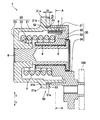
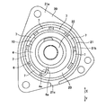
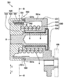
- FIG. 2 is a cross-sectional view of the auto tensioner shown in FIG. 3 is a cross-sectional view taken along line AA in FIG. 4 is a view of the fixing member and members attached to the fixing member shown in FIG. 1 as viewed from the right side in FIG.
- FIG. 5 is a perspective view of the fixing member shown in FIG.
- FIG. 6 is a partial cross-sectional view of an auto tensioner according to a modification of the first embodiment.
- FIG. 7 is a partial cross-sectional view of an auto tensioner according to a modification of the first embodiment.
- FIG. 8 is a partial cross-sectional view of an auto tensioner according to a modification of the first embodiment.
- the auto tensioner 1 adjusts the tension of a transmission belt that transmits the power of an engine crankshaft to an auxiliary machine, and is attached to an engine block of an automobile.
- the auto tensioner 1 includes a fixing member 20, a rotating member 30, a coil spring 4, a drainage mechanism 50, a leaf spring (elastic body) 6, and a plurality of friction members 7. It has.
- a pulley 100 around which a transmission belt is wound is attached to the rotating member 30.
- the rotating member 30 is rotatably supported with respect to the fixed member 20 via the shaft 8 and the bush 9.
- the direction of the rotation axis of the rotation member 30 (the axial direction of the shaft 8) is simply referred to as the axial direction.
- the fixing member 20 is fixed to an engine block (not shown) so that the vertical direction is the vertical direction shown by FIGS. 2 and 4 (arrow X: upward direction, arrow Y: downward direction).
- the fixing member 20 includes an outer cylindrical portion (first cylindrical portion) 21, an inner cylindrical portion 22 disposed inside the outer cylindrical portion 21, and an annular bottom that connects the outer cylindrical portion 21 and the inner cylindrical portion 22. It is comprised with the wall part 23.
- FIG. The inner cylinder portion 22 is fixed to the shaft 8 so as not to be relatively rotatable.
- a substantially triangular flange portion 21 a is provided at a substantially central portion in the axial direction of the outer cylinder portion 21.
- “upper” and “lower” mean “vertically upward” and “vertically downward”, respectively, unless otherwise specified.
- a water retaining groove 21b is formed on the outer peripheral surface (specifically, the flange portion 21a) of the outer cylinder portion 21 over the entire periphery.
- the depth direction of the water reservoir groove 21b is the axial direction, and the depth H (see FIG. 2) of the water reservoir groove 21b is, for example, 2 to 5 mm. If the water reservoir groove 21b is too deep, the strength of the fixing member 20 cannot be maintained. If the water reservoir groove 21b is too shallow, the function of storing water is not achieved. Therefore, the depth of the water reservoir groove 21b is preferably within the above range.
- a notch 21c is formed in the peripheral wall (flange portion 21a) on the radially outer side of the water reservoir groove 21b.
- the cutout 21c constitutes the drainage port 53 of the drainage mechanism 50.
- the fixing member 20 is installed so that the drainage port 53 is located below the water collecting groove 21 b.
- the circumferential range L of the drainage port 53 is preferably set within a range of 20 degrees ( ⁇ in FIG. 3) clockwise and counterclockwise from a position directly below the central axis of rotation.
- the rotating member 30 has an annular shape that connects the outer cylinder part (second cylinder part) 31, the inner cylinder part 32 disposed inside the outer cylinder part 31, and the outer cylinder part 31 and the inner cylinder part 32.
- a bottom wall portion 33 and a pulley support portion 34 are included.
- a pulley 100 is detachably attached to the pulley support portion 34.
- the inner cylinder part 32 is arranged side by side with the inner cylinder part 22 of the fixing member 20 in the axial direction.
- the inner cylinder portion 32 is attached to the shaft 8 via the bush 9 so as to be relatively rotatable. Thereby, the rotation member 30 can rotate relative to the fixed member 20.
- the outer diameter of the right side part in FIG. 2 is larger than the left side part.
- the surface facing the coil spring 4 of the portion having the large outer diameter is formed in a spiral shape along the coil spring 4. Therefore, as shown in FIG. 3, a step 32a is formed at the boundary between the start position and the end position of the spiral.
- the outer cylinder portion 31 of the rotation member 30 is omitted.
- the outer cylinder part 31 is arranged so as to overlap with the outer cylinder part 21 of the fixing member 20 in the radial direction. Specifically, the outer cylinder portion 31 is disposed on the radially outer side of the outer cylinder portion 21 of the fixing member 20. Further, the distal end portion of the outer cylinder portion 31 is inserted into a water reservoir groove 21 b formed in the outer cylinder portion 21 of the fixing member 20. Therefore, the gap between the water reservoir groove 21b and the distal end portion of the outer cylinder portion 31 of the rotating member 30 is U-shaped. This U-shaped gap constitutes a water passage 52 of the drainage mechanism 50. The water passage 52 is formed over the entire circumference.
- a portion of the gap between the outer peripheral surface of the outer cylindrical portion 21 of the fixing member 20 and the outer peripheral surface of the outer cylindrical portion 31 of the rotating member 30 constitutes the water inlet 51 of the drainage mechanism 50 except for the drain port 53. is doing.
- the water inlet 51 is open along the circumferential direction.
- the interval D (see FIG. 2) between the water inlets 51 is, for example, 1 to 3 mm. If the water inlet 51 is too large, there is a problem that dust easily enters and the gap is clogged. If the water inlet 51 is too small, dust tends to accumulate. Therefore, the interval between the water inlets 51 is preferably within the above range.
- the drainage mechanism 50 is for preventing muddy water and the like from entering the auto tensioner 1.
- the drainage mechanism 50 is provided at a boundary portion between the outer cylinder portion 21 of the fixing member 20 and the outer cylinder portion 31 of the rotating member 30, and includes the above-described water inlet 51, water passage 52, and drainage port 53. ing.
- the coil spring 4 is disposed inside the outer tube portion 21 of the fixing member 20 and the outer tube portion 31 of the rotating member 30.
- the coil spring 4 has one end 4a (the right end in FIG. 2) locked to the rotating member 30, and the other end (the left end in FIG. 2) locked to the fixing member 20.
- the rotating member 30 is urged to rotate in one direction with respect to the fixed member 20.
- the urging direction of the coil spring 4 is a direction in which tension is applied to the transmission belt wound around the pulley 100.
- the end portion 4 a of the coil spring 4 presses the stepped portion 32 a of the rotating member 30 via the leaf spring 6, whereby the end portion of the coil spring 4 is engaged with the rotating member 30. It has been stopped.
- the method of locking the end of the coil spring 4 with respect to the fixing member 20 is not particularly limited.
- the other end of the coil spring 4 is fitted into the groove formed in the fixing member 20 or the diameter formed on the fixing member 20 is.
- the coil spring 4 is locked by press-fitting the bent end of the coil spring 4 into a locking hole extending in the direction or the axial direction.
- the coil spring 4 is attached with a coil spring support member 10 for suppressing the inclination of the posture of the coil spring 4.
- the coil spring support member 10 is sandwiched between the friction member 7 and the coil spring 4 (see FIG. 4).
- the coil spring support member 10 need not be provided.
- the leaf spring (elastic body) 6 is disposed inside the distal end portion of the outer cylinder portion 21 of the fixing member 20, and extends along the inner peripheral surface of the outer cylinder portion 21. It is extended. As shown in FIG. 3, one end portion 6 a of the leaf spring 6 is bent 90 degrees radially inward and is sandwiched between the stepped portion 32 a of the rotating member 30 and the end portion 4 a of the coil spring 4. . As a result, the end 6 a of the leaf spring 6 is locked to the rotating member 30. The end of the leaf spring 6 opposite to the end 6a is a free end.
- the leaf spring 6 is formed with a plurality of attachment holes 6b for attaching the plurality of friction members 7 in the circumferential direction.
- a plurality (seven in this embodiment) of friction members 7 are disposed between the inner peripheral surface of the outer cylindrical portion 21 of the fixing member 20 and the leaf spring 6.
- the plurality of friction members 7 are arranged outside the circumferential range L of the drain port 53 and aligned in the circumferential direction.
- the plurality of friction members 7 are preferably disposed outside the range of 20 degrees ( ⁇ in FIG. 3) clockwise and counterclockwise from a position directly below the central axis of rotation.
- the friction member 7 is coupled to the leaf spring 6 so as not to move relative to the leaf spring 6 by being fitted into an attachment hole 6 b formed in the leaf spring 6.
- the friction member 7 receives the self-elastic expansion force of the leaf spring 6 and always contacts the inner peripheral surface of the outer cylinder portion 21 of the fixing member 20.
- the friction member 7 is made of, for example, a synthetic resin such as a polyamide resin such as nylon 66, a polyacetal resin, a polyarylate resin, a phenol resin, a polyphenylene sulfide (PPS) resin, or an ultrahigh molecular polyethylene resin as a main component.
- the frictional force generated between the friction member 7 and the outer cylinder portion 21 of the fixing member 20 is made different depending on whether the belt tension increases or decreases. Can do.
- the auto tensioner 1 of the present embodiment is installed in an orientation in which the axial direction is substantially horizontal, mud water, engine oil, and the like flowing into the water inlet 51 are passed through the water inlet 51 in the radial direction. After flowing into the water channel 52 and moving downward in the water channel 52 along the circumferential direction, the water channel 52 is discharged outside. Therefore, muddy water and the like can be smoothly discharged while suppressing muddy water and the like from entering the auto tensioner 1. As a result, it is possible to prevent the friction member 7 from being accelerated by muddy water or the like that has entered between the friction member 7 and the object to be slid, and the life of the friction member 7 can be extended.
- the water flow path 52 is U-shaped by inserting the front-end
- the drainage port 53 communicates with the lower part of the water passage 52, the muddy water or the like flowing into the water passage 52 can be reliably discharged from the drainage port 53.
- the friction member 7 does not exist inside the outer cylinder portion 21 of the fixing member 20 in the circumferential range L of the drain port 53. Therefore, even if muddy water or the like rolled up by the axle or the like from the lower part of the vehicle adheres to the drain port 53 and enters the inside, the friction member is located at a position that is most susceptible to the influence of muddy water or the like entering from the drain port 53. Since it does not exist, wear of the friction member 7 can be suppressed.
- the position of the drain port 53 is constant regardless of the rotation of the rotating member 30.
- the depth direction of the water reservoir groove 21b is an axial direction, the strength reduction of the fixing member 20 by providing a water reservoir groove can be suppressed compared with the case where the depth direction is a radial direction. .
- auto tensioner 1 of this embodiment can be implemented with the following modifications.
- all of the plurality of friction members 7 are disposed outside the circumferential range L of the drain port 53, but one of the plurality of friction members 7 is disposed within the circumferential range L of the drain port 53. May be.
- the leaf spring 6 and the friction member 7 for attenuating the swinging of the rotating member 30 may not be provided. Further, it is not necessary to provide a plurality of friction members 7, and one friction member 7 may be provided.
- the number of drain ports 53 is one, but a plurality of drain ports 53 may be provided. That is, the number of the notches 21c formed in the peripheral wall on the radially outer side of the water reservoir groove 21b may be plural.
- the portion of the outer peripheral surface of the outer cylindrical portion 21 of the fixing member 20 that faces the inner peripheral surface of the outer cylindrical portion 31 of the rotating member 30 is flat (the diameter is constant). It is not limited to the configuration.
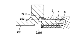
- a groove 221d may be formed on the radially inner peripheral wall of the water reservoir groove 221b as in the outer cylinder portion 221 of the fixing member shown in FIG.
- the groove 221d may be formed in the entire circumferential direction of the water reservoir groove 221b, or may be formed only in a part of the circumferential range of the water reservoir groove 221b.
- the distal end portion of the outer cylinder portion 31 of the rotating member 30 is inserted inside the water reservoir groove 21b formed in the outer cylinder portion 21 of the fixing member 20.
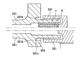
- the distal end portion of the outer cylinder portion 331 of the rotating member may not be inserted inside the water reservoir groove 321b formed in the outer cylinder portion 321 of the fixing member.
- the drainage port 353 is configured by a notch 321c formed on the radially outer peripheral wall of the water reservoir groove 321b, as in the present embodiment.
- the water reservoir groove 21b is formed so that the depth direction is the axial direction.
- the water reservoir groove 421b is formed so that the depth direction is the radial direction. It may be formed.
- the drainage port 453 is configured by a gap between a notch 431a formed at the distal end portion of the outer cylinder portion 431 of the rotating member and the outer cylinder portion 421 of the fixing member.
- the auto tensioner 501 of the present embodiment includes a fixing member 520, a rotating member 530, a coil spring 4, a drainage mechanism 550, a leaf spring (elastic body) 6, and a plurality of members. And a friction member 7.
- the outer cylinder portion 521 of the fixing member 520 is omitted.
- the fixing member 520 includes an outer cylinder part (first cylinder part) 521, an inner cylinder part 522, and a bottom wall part 523.
- the inner cylinder part 522 is fixed to the shaft 8 so as not to be relatively rotatable.
- the inner cylinder portion 522 is formed in a spiral shape so that the surface facing the coil spring 4 in the axial direction is along the coil spring 4. Therefore, as shown in FIG. 10, a step 522a is formed at the boundary between the start position and the end position of the spiral.
- the rotating member 530 includes an outer cylinder part (second cylinder part) 531, an inner cylinder part 532, a bottom wall part 533, and a pulley support part 534.
- the pulley support portion 534 is formed in the same manner as the pulley support portion 34 of the first embodiment.
- the inner cylinder portion 532 is attached to the shaft 8 via the bush 9 so as to be relatively rotatable.
- the outer diameter of the outer cylinder 531 is larger on the base side than on the tip side.
- a portion having a large outer diameter is defined as a large diameter portion 531a.
- the depth direction of the water reservoir groove 531b is the axial direction.
- a notch 531c is formed in the peripheral wall on the radially outer side of the water reservoir groove 531b.
- the cutout 531c constitutes the drainage port 553 of the drainage mechanism 550.
- the auto tensioner 501 of the present embodiment is installed so that the notch 531c (drain port 553) of the rotating member 530 is located below the water reservoir groove 531b.
- the circumferential range L of the drain outlet 553 is preferably a range in which the circumferential angle is 40 degrees or less. Note that the swing angle of the rotating member 530 is in the range of +15 degrees to ⁇ 15 degrees.
- the distal end portion of the outer cylinder portion 531 of the rotating member 530 is disposed so as to overlap the outer cylinder portion 521 of the fixing member 520 in the radial direction.
- the outer cylindrical portion 31 of the rotating member 30 is disposed on the radially outer side of the outer cylindrical portion 21 of the fixing member 20.
- the outer cylindrical portion 521 of the fixing member 520 is The outer cylindrical portion 531 of the rotating member 530 is disposed on the radially outer side.
- the distal end portion of the outer cylinder portion 521 of the fixing member 520 is inserted inside a water reservoir groove 531b formed in the outer cylinder portion 531 of the rotating member 530. Therefore, the gap between the water collecting groove 531b and the tip of the outer cylinder portion 521 of the fixing member 520 is U-shaped. This U-shaped gap constitutes a water passage 552 of the drainage mechanism 550.
- the drainage mechanism 550 includes the above-described water inlet 551, water passage 552, and drainage port 553.
- Both ends of the coil spring 4 are locked to the fixing member 520 and the rotating member 530, respectively.
- the method of locking the end of the coil spring 4 with respect to the fixing member 520 is the same as the method of locking the end of the coil spring 4 with respect to the rotating member 30 in the first embodiment. That is, the left end 4 b of the coil spring 4 in FIG. 10 presses the stepped portion 522 a of the fixing member 520 via the leaf spring 6, whereby the end 4 b of the coil spring 4 is locked to the fixing member 520.
- the method of locking the end of the coil spring 4 with respect to the rotating member 530 is not particularly limited.
- the leaf spring 6 is disposed along the inner peripheral surface of the outer cylinder portion 21 of the fixing member 20, but in this embodiment, the leaf spring 6 is the outer cylinder portion of the rotating member 530. It is arranged along the inner peripheral surface of 531. Further, one end of the leaf spring 6 is bent 90 degrees radially inward and is sandwiched between the step 522 a of the bottom wall 523 of the fixing member 520 and the end 4 b of the coil spring 4. The other end of the leaf spring 6 is a free end.
- the plurality of friction members 7 are in contact with the inner peripheral surface of the outer cylinder portion 21 of the fixed member 20, but in the present embodiment, the plurality of friction members 7 are outside the rotating member 530.
- the tube portion 531 is in contact with the inner peripheral surface.
- the plurality of friction members 7 are arranged outside the circumferential range L of the drain port 553 in the circumferential direction. As shown in FIG. 9, when the drain outlet 553 is positioned at the lowermost portion of the water collecting groove 531b, the plurality of friction members 7 are each rotated 20 degrees clockwise and counterclockwise from the position just below the central axis of rotation (see FIG. 9).
- the plurality of friction members 7 between the outer cylinder portion 531 and the leaf spring 6 so as to be located outside the range of ⁇ ) in FIG.
- the method for coupling the leaf spring 6 and the friction member 7 is the same as in the first embodiment.
- the rotating member 530 rotates in the clockwise direction of FIG. 10 by the urging force of the coil spring 4.
- the friction member 7 slides against the inner peripheral surface of the outer cylindrical portion 531 of the rotating member 530 and the leaf spring 6 is slightly reduced in diameter.
- the force with which the friction member 7 is pressed against the inner peripheral surface of the outer cylinder portion 531 of the rotating member 530 is reduced, only a small friction force is generated between the friction member 7 and the outer cylinder portion 531 of the rotating member 530. Does not occur.
- the frictional force generated between the friction member 7 and the outer cylindrical portion 531 of the rotating member 530 can be made different between when the belt tension increases and when the belt tension decreases.
- muddy water or the like that flows into the water inlet 551 flows into the water passage 552, moves downward along the circumferential direction of the water passage 552, and then is discharged from the drain outlet 553 to the outside. Is done. Therefore, the collected muddy water and the like can be smoothly discharged while suppressing the muddy water and the like from entering the auto tensioner 501.
- the water passage 552 has a U-shape, the intrusion of muddy water or the like into the auto tensioner 501 can be more reliably suppressed as in the first embodiment.
- the drainage port 553 communicates with the lower part of the water passage 552, the muddy water or the like that has flowed into the water passage 552 can be reliably discharged from the drainage port 553.
- the friction member 7 does not exist inside the outer cylinder portion 531 of the rotating member 530 in the circumferential range L of the drain port 553. Therefore, even if muddy water or the like may enter the inside from the drain port 553, the friction member does not exist at a position that is most susceptible to the influence of the muddy water or the like that has entered from the drain port 553, so that wear of the friction member 7 can be suppressed. .
- auto tensioner 501 of the present embodiment can be implemented with the same modifications as the modified example of the first embodiment described above.
Landscapes
- Engineering & Computer Science (AREA)
- General Engineering & Computer Science (AREA)
- Mechanical Engineering (AREA)
- Devices For Conveying Motion By Means Of Endless Flexible Members (AREA)
Abstract
Description
第1筒部を有する固定部材と、
少なくとも一部分が前記第1筒部と径方向に重なって配置される第2筒部を有し、前記固定部材に対して回動自在に支持される回動部材と、
前記第1筒部及び第2筒部の内側に収容されると共に、その一端が前記固定部材に係止され、他端が前記回動部材に係止されるコイルバネと、
前記第1筒部と第2筒部との境界部に設けられた排水機構とを備えており、
前記排水機構は、
前記第1筒部の外周面と前記第2筒部の外周面との隙間で構成され、周方向に沿って開口する入水口と、
前記2つの筒部の一方の外周面に周方向に沿って形成された水溜め溝と他方の前記筒部との隙間で構成され、前記入水口に連通する通水路と、
前記通水路の径方向外側の周壁に形成された少なくとも1つの排水口と、を有する。
以下、本発明の第1実施形態に係るオートテンショナ1について説明する。
本実施形態のオートテンショナ1は、エンジンのクランクシャフトの動力を補機に伝達する伝動ベルトの張力を調整するものであって、自動車のエンジンブロックに取り付けられる。
この変更例の場合、排水口353は、本実施形態と同様に、水溜め溝321bの径方向外側の周壁に形成された切り欠き321cで構成される。
この変更例の場合、排水口453は、回動部材の外筒部431の先端部に形成された切り欠き431aと固定部材の外筒部421との隙間で構成される。
次に、本発明の第2実施形態に係るオートテンショナ501について説明する。但し、第1実施形態と同様の構成を有するものについては、同じ符号を用いて適宜その説明を省略する。
本出願は、2011年4月28日出願の日本特許出願2011-100826及び2012年3月9日出願の日本特許出願2012-52991に基づくものであり、その内容はここに参照として取り込まれる。
4 コイルバネ
6 板バネ(弾性体)
7 摩擦部材
20、520 固定部材
21、221、321、421、521 外筒部(第1筒部)
21b、221b、321b、421b、531b 水溜め溝
30、530 回動部材
31、331、431、531 外筒部(第2筒部)
50、550 排水機構
51、551 入水口
52、252、552 通水路
53、353、453、553 排水口
Claims (5)
- 第1筒部を有する固定部材と、
少なくとも一部分が前記第1筒部と径方向に重なって配置される第2筒部を有し、前記固定部材に対して回動自在に支持される回動部材と、
前記第1筒部及び第2筒部の内側に収容されると共に、その一端が前記固定部材に係止され、他端が前記回動部材に係止されるコイルバネと、
前記第1筒部と第2筒部との境界部に設けられた排水機構とを備えており、
前記排水機構は、
前記第1筒部の外周面と前記第2筒部の外周面との隙間で構成され、周方向に沿って開口する入水口と、
前記2つの筒部の一方の外周面に周方向に沿って形成された水溜め溝と他方の前記筒部との隙間で構成され、前記入水口に連通する通水路と、
前記通水路の径方向外側の周壁に形成された少なくとも1つの排水口とを有する、オートテンショナ。 - 前記水溜め溝の深さ方向が、前記筒部の筒軸方向であって、
前記水溜め溝内に、前記2つの筒部のうち水溜め溝が形成されていない方の筒部の先端部が挿入されている、請求項1に記載のオートテンショナ。 - 一端が前記回動部材と前記固定部材の一方の部材に係止され、他端が自由端であり、前記回動部材と前記固定部材の他方の部材の前記筒部の内周面に沿って延在する弾性体と、
前記弾性体に対して周方向に相対移動不能に結合され、前記回動部材と前記固定部材の前記他方の部材の前記筒部の内周面と接触する摩擦部材とをさらに備える、請求項1または2に記載のオートテンショナ。 - 前記排水口が、前記通水路の下部と連通する、請求項1~3のいずれかに記載のオートテンショナ。
- 前記排水口が、前記他方の部材の前記筒部に形成されており、
前記排水口の周方向範囲において、前記他方の部材の前記筒部の内側に、前記摩擦部材が存在しない、請求項3に記載のオートテンショナ。
Priority Applications (5)
| Application Number | Priority Date | Filing Date | Title |
|---|---|---|---|
| BR112013027889-7A BR112013027889B1 (pt) | 2011-04-28 | 2012-04-27 | autotensor |
| CN201280020554.7A CN103492755B (zh) | 2011-04-28 | 2012-04-27 | 自动张紧器 |
| CA2834431A CA2834431C (en) | 2011-04-28 | 2012-04-27 | Auto-tensioner |
| US14/113,717 US9206888B2 (en) | 2011-04-28 | 2012-04-27 | Auto-tensioner |
| EP12776318.3A EP2703690B1 (en) | 2011-04-28 | 2012-04-27 | Auto-tensioner |
Applications Claiming Priority (4)
| Application Number | Priority Date | Filing Date | Title |
|---|---|---|---|
| JP2011-100826 | 2011-04-28 | ||
| JP2011100826 | 2011-04-28 | ||
| JP2012-052991 | 2012-03-09 | ||
| JP2012052991A JP5627621B2 (ja) | 2011-04-28 | 2012-03-09 | オートテンショナ |
Publications (1)
| Publication Number | Publication Date |
|---|---|
| WO2012147957A1 true WO2012147957A1 (ja) | 2012-11-01 |
Family
ID=47072468
Family Applications (1)
| Application Number | Title | Priority Date | Filing Date |
|---|---|---|---|
| PCT/JP2012/061467 Ceased WO2012147957A1 (ja) | 2011-04-28 | 2012-04-27 | オートテンショナ |
Country Status (7)
| Country | Link |
|---|---|
| US (1) | US9206888B2 (ja) |
| EP (1) | EP2703690B1 (ja) |
| JP (1) | JP5627621B2 (ja) |
| CN (1) | CN103492755B (ja) |
| BR (1) | BR112013027889B1 (ja) |
| CA (1) | CA2834431C (ja) |
| WO (1) | WO2012147957A1 (ja) |
Cited By (3)
| Publication number | Priority date | Publication date | Assignee | Title |
|---|---|---|---|---|
| US20110201466A1 (en) * | 2008-10-10 | 2011-08-18 | Mitsuboshi Belting Ltd. | Auto-tensioner |
| US9726051B2 (en) | 2012-10-22 | 2017-08-08 | Litens Automotive Partnership | Tensioner with increased damping |
| US9869379B2 (en) | 2013-09-11 | 2018-01-16 | Litens Automotive Partnership | Tensioner with increased damping and arm on base cup configuration |
Families Citing this family (13)
| Publication number | Priority date | Publication date | Assignee | Title |
|---|---|---|---|---|
| JPH062972B2 (ja) | 1986-01-20 | 1994-01-12 | 株式会社豊田自動織機製作所 | 無杼織機における緯糸処理方法 |
| JP2516611Y2 (ja) | 1994-02-04 | 1996-11-06 | 津田駒工業株式会社 | 不良糸除去装置 |
| JP5941858B2 (ja) * | 2013-03-01 | 2016-06-29 | 三ツ星ベルト株式会社 | オートテンショナ |
| US20170138445A1 (en) * | 2014-06-27 | 2017-05-18 | Litens Automotive Partnership | Endless drive arrangement with active idler |
| JP6290944B2 (ja) | 2015-02-20 | 2018-03-07 | 三ツ星ベルト株式会社 | プーリ構造体 |
| CN107250612B (zh) * | 2015-02-25 | 2020-04-07 | 戴科欧洲有限公司 | 具有改进的阻尼装置的张紧器 |
| FR3038028B1 (fr) * | 2015-06-24 | 2018-11-23 | Aktiebolaget Skf | Dispositif de galet tendeur |
| US10859141B2 (en) * | 2015-10-28 | 2020-12-08 | Litens Automotive Partnership | Tensioner with first and second damping members and increased damping |
| JP6706143B2 (ja) * | 2016-05-20 | 2020-06-03 | バンドー化学株式会社 | オートテンショナ |
| US10122904B2 (en) * | 2016-07-11 | 2018-11-06 | Gopro, Inc. | Drain mechanism for camera controller |
| US10989280B2 (en) * | 2017-06-16 | 2021-04-27 | Gates Corporation | Tensioner |
| KR102001765B1 (ko) * | 2018-01-03 | 2019-07-18 | 지엠 글로벌 테크놀러지 오퍼레이션스 엘엘씨 | 미로구조가 형성된 텐셔너 어셈블리 |
| CN116123260A (zh) * | 2023-03-27 | 2023-05-16 | 奇瑞汽车股份有限公司 | 张紧器和发动机的附件轮系 |
Citations (7)
| Publication number | Priority date | Publication date | Assignee | Title |
|---|---|---|---|---|
| JPH09189348A (ja) * | 1995-12-18 | 1997-07-22 | Gates Corp:The | テンショナ |
| JP2003254399A (ja) * | 2002-02-28 | 2003-09-10 | Mitsuboshi Belting Ltd | オートテンショナ |
| JP2004204937A (ja) | 2002-12-25 | 2004-07-22 | Gates Unitta Asia Co | オートテンショナ |
| JP2005069356A (ja) * | 2003-08-25 | 2005-03-17 | Bando Chem Ind Ltd | オートテンショナ |
| JP2005299810A (ja) * | 2004-04-13 | 2005-10-27 | Gates Unitta Asia Co | オートテンショナとオートテンショナの製造方法 |
| JP2009533619A (ja) * | 2006-04-12 | 2009-09-17 | ライテンズ オートモーティブ ゲーエムベーハー | エンドレス伝動用のテンショナ |
| WO2010041747A1 (ja) * | 2008-10-10 | 2010-04-15 | 三ツ星ベルト株式会社 | オートテンショナ |
Family Cites Families (14)
| Publication number | Priority date | Publication date | Assignee | Title |
|---|---|---|---|---|
| US4285676A (en) * | 1979-12-17 | 1981-08-25 | Dyneer Corporation | Mechanical belt tensioner construction |
| US4464146A (en) * | 1982-05-17 | 1984-08-07 | Imperial Clevite Inc. | Apparatus for maintaining tension of an endless drive member |
| JP3159293B2 (ja) | 1995-08-01 | 2001-04-23 | 本田技研工業株式会社 | オートテンショナー |
| US5647813A (en) * | 1995-12-18 | 1997-07-15 | The Gates Corporation | Tensioner with damping mechanism and belt drive system |
| WO1999028652A2 (en) * | 1997-11-26 | 1999-06-10 | Litens Automotive Partnership | Rotary belt tensioner with hydraulic damping |
| CA2354273C (en) * | 1998-12-08 | 2007-10-16 | Litens Automotive Partnership | Tensioner with self-limiting angular stroke |
| AU2001296474A1 (en) * | 2000-10-03 | 2002-04-15 | The Gates Corporation | Accessory and motor/generator belt drive tensioner |
| US6609988B1 (en) | 2001-05-24 | 2003-08-26 | The Gates Corporation | Asymmetric damping tensioner belt drive system |
| DE10131916A1 (de) * | 2001-07-05 | 2003-01-23 | Muhr & Bender Kg | Spanneinrichtung für Zugmittel, insbesondere Riemenspanneinrichtung |
| JP4364750B2 (ja) | 2004-08-20 | 2009-11-18 | ゲイツ・ユニッタ・アジア株式会社 | テンショナおよびラビリンスシール |
| JP5242544B2 (ja) * | 2006-03-22 | 2013-07-24 | ライテンズ オートモーティブ パートナーシップ | 可撓性ドライブ用テンショナ |
| US7662057B2 (en) * | 2007-06-08 | 2010-02-16 | Schaeffler Kg | Eccentric tensioning device |
| DE102007031298A1 (de) | 2007-07-05 | 2009-01-08 | Schaeffler Kg | Dämpfungsvorrichtung eines mechanischen Spannsystems für einen Zugmitteltrieb |
| JP5944774B2 (ja) * | 2012-07-24 | 2016-07-05 | Ntn株式会社 | テンショナ装置 |
-
2012
- 2012-03-09 JP JP2012052991A patent/JP5627621B2/ja active Active
- 2012-04-27 CN CN201280020554.7A patent/CN103492755B/zh active Active
- 2012-04-27 EP EP12776318.3A patent/EP2703690B1/en active Active
- 2012-04-27 US US14/113,717 patent/US9206888B2/en active Active
- 2012-04-27 BR BR112013027889-7A patent/BR112013027889B1/pt active IP Right Grant
- 2012-04-27 WO PCT/JP2012/061467 patent/WO2012147957A1/ja not_active Ceased
- 2012-04-27 CA CA2834431A patent/CA2834431C/en active Active
Patent Citations (8)
| Publication number | Priority date | Publication date | Assignee | Title |
|---|---|---|---|---|
| JPH09189348A (ja) * | 1995-12-18 | 1997-07-22 | Gates Corp:The | テンショナ |
| JP2003254399A (ja) * | 2002-02-28 | 2003-09-10 | Mitsuboshi Belting Ltd | オートテンショナ |
| JP2004204937A (ja) | 2002-12-25 | 2004-07-22 | Gates Unitta Asia Co | オートテンショナ |
| JP2005069356A (ja) * | 2003-08-25 | 2005-03-17 | Bando Chem Ind Ltd | オートテンショナ |
| JP2005299810A (ja) * | 2004-04-13 | 2005-10-27 | Gates Unitta Asia Co | オートテンショナとオートテンショナの製造方法 |
| JP2009533619A (ja) * | 2006-04-12 | 2009-09-17 | ライテンズ オートモーティブ ゲーエムベーハー | エンドレス伝動用のテンショナ |
| WO2010041747A1 (ja) * | 2008-10-10 | 2010-04-15 | 三ツ星ベルト株式会社 | オートテンショナ |
| JP2010112549A (ja) | 2008-10-10 | 2010-05-20 | Tomokazu Ishida | オートテンショナ |
Non-Patent Citations (1)
| Title |
|---|
| See also references of EP2703690A4 |
Cited By (5)
| Publication number | Priority date | Publication date | Assignee | Title |
|---|---|---|---|---|
| US20110201466A1 (en) * | 2008-10-10 | 2011-08-18 | Mitsuboshi Belting Ltd. | Auto-tensioner |
| US8678965B2 (en) * | 2008-10-10 | 2014-03-25 | Mitsuboshi Belting Ltd. | Auto-tensioner |
| US9726051B2 (en) | 2012-10-22 | 2017-08-08 | Litens Automotive Partnership | Tensioner with increased damping |
| US9790817B2 (en) | 2012-10-22 | 2017-10-17 | Litens Automotive Partnership | Tensioner with increased damping |
| US9869379B2 (en) | 2013-09-11 | 2018-01-16 | Litens Automotive Partnership | Tensioner with increased damping and arm on base cup configuration |
Also Published As
| Publication number | Publication date |
|---|---|
| CA2834431C (en) | 2017-06-20 |
| EP2703690B1 (en) | 2017-09-13 |
| CA2834431A1 (en) | 2012-11-01 |
| EP2703690A1 (en) | 2014-03-05 |
| US9206888B2 (en) | 2015-12-08 |
| CN103492755A (zh) | 2014-01-01 |
| BR112013027889B1 (pt) | 2021-05-04 |
| CN103492755B (zh) | 2016-05-18 |
| JP2012237444A (ja) | 2012-12-06 |
| JP5627621B2 (ja) | 2014-11-19 |
| US20140051533A1 (en) | 2014-02-20 |
| EP2703690A4 (en) | 2015-04-08 |
Similar Documents
| Publication | Publication Date | Title |
|---|---|---|
| JP5627621B2 (ja) | オートテンショナ | |
| CN102996634B (zh) | 中心轴承支撑件 | |
| US10240678B2 (en) | Radial shaft seal assembly with axially adaptive debris exclusion face lip and oil seal face lip | |
| US8474825B2 (en) | Sealing device | |
| EP2910818B1 (en) | Hydraulic automatic tensioner for auxiliary device | |
| US8714561B2 (en) | Oil seal | |
| CN104976295B (zh) | 皮带张紧装置 | |
| US10788106B2 (en) | Clearance-free self-aligning bearing on the decoupling tensioner | |
| CN106068404B (zh) | 皮带张紧器 | |
| JP5167808B2 (ja) | 自動変速機の潤滑油供給装置 | |
| CN107923498B (zh) | 皮带张紧器 | |
| US4723934A (en) | Belt tensioner | |
| JP2009174683A (ja) | 樹脂プーリ付き軸受 | |
| CN117730217A (zh) | 改进的过滤带轮 | |
| US20140274511A1 (en) | Belt tensioner for a power transmission belt system | |
| CN111692201A (zh) | 密封装置和滚动轴承装置 | |
| CN107076017B (zh) | 涡轮增压器 | |
| JP2012163177A (ja) | 逆止弁および油圧供給装置 | |
| CN116888383A (zh) | 具有平衡扭转弹簧力的高偏移皮带张紧器 | |
| CN106286732B (zh) | 张紧辊装置 | |
| JP6367128B2 (ja) | オートテンショナ | |
| JP2003028205A (ja) | ラチェットワンウェイクラッチ及びラチェットワンウェイクラッチを用いたステータ | |
| JP4276100B2 (ja) | 緩衝器 | |
| JP4451314B2 (ja) | 油圧式テンショナ | |
| JP6729117B2 (ja) | 円すいころ軸受 |
Legal Events
| Date | Code | Title | Description |
|---|---|---|---|
| 121 | Ep: the epo has been informed by wipo that ep was designated in this application |
Ref document number: 12776318 Country of ref document: EP Kind code of ref document: A1 |
|
| WWE | Wipo information: entry into national phase |
Ref document number: 14113717 Country of ref document: US |
|
| ENP | Entry into the national phase |
Ref document number: 2834431 Country of ref document: CA |
|
| NENP | Non-entry into the national phase |
Ref country code: DE |
|
| REEP | Request for entry into the european phase |
Ref document number: 2012776318 Country of ref document: EP |
|
| WWE | Wipo information: entry into national phase |
Ref document number: 2012776318 Country of ref document: EP |
|
| REG | Reference to national code |
Ref country code: BR Ref legal event code: B01A Ref document number: 112013027889 Country of ref document: BR |
|
| ENP | Entry into the national phase |
Ref document number: 112013027889 Country of ref document: BR Kind code of ref document: A2 Effective date: 20131029 |