WO2012150686A1 - 無線基地局装置、移動端末装置、無線通信方法及び無線通信システム - Google Patents
無線基地局装置、移動端末装置、無線通信方法及び無線通信システム Download PDFInfo
- Publication number
- WO2012150686A1 WO2012150686A1 PCT/JP2012/060981 JP2012060981W WO2012150686A1 WO 2012150686 A1 WO2012150686 A1 WO 2012150686A1 JP 2012060981 W JP2012060981 W JP 2012060981W WO 2012150686 A1 WO2012150686 A1 WO 2012150686A1
- Authority
- WO
- WIPO (PCT)
- Prior art keywords
- information
- mobile terminal
- cell
- base station
- pattern
- Prior art date
- Legal status (The legal status is an assumption and is not a legal conclusion. Google has not performed a legal analysis and makes no representation as to the accuracy of the status listed.)
- Ceased
Links
Images


Classifications
-
- H—ELECTRICITY
- H04—ELECTRIC COMMUNICATION TECHNIQUE
- H04L—TRANSMISSION OF DIGITAL INFORMATION, e.g. TELEGRAPHIC COMMUNICATION
- H04L27/00—Modulated-carrier systems
- H04L27/26—Systems using multi-frequency codes
- H04L27/2601—Multicarrier modulation systems
- H04L27/2602—Signal structure
- H04L27/261—Details of reference signals
- H04L27/2613—Structure of the reference signals
-
- H—ELECTRICITY
- H04—ELECTRIC COMMUNICATION TECHNIQUE
- H04L—TRANSMISSION OF DIGITAL INFORMATION, e.g. TELEGRAPHIC COMMUNICATION
- H04L5/00—Arrangements affording multiple use of the transmission path
- H04L5/003—Arrangements for allocating sub-channels of the transmission path
- H04L5/0032—Distributed allocation, i.e. involving a plurality of allocating devices, each making partial allocation
- H04L5/0035—Resource allocation in a cooperative multipoint environment
-
- H—ELECTRICITY
- H04—ELECTRIC COMMUNICATION TECHNIQUE
- H04L—TRANSMISSION OF DIGITAL INFORMATION, e.g. TELEGRAPHIC COMMUNICATION
- H04L5/00—Arrangements affording multiple use of the transmission path
- H04L5/0001—Arrangements for dividing the transmission path
- H04L5/0014—Three-dimensional division
- H04L5/0023—Time-frequency-space
-
- H—ELECTRICITY
- H04—ELECTRIC COMMUNICATION TECHNIQUE
- H04L—TRANSMISSION OF DIGITAL INFORMATION, e.g. TELEGRAPHIC COMMUNICATION
- H04L5/00—Arrangements affording multiple use of the transmission path
- H04L5/003—Arrangements for allocating sub-channels of the transmission path
- H04L5/0048—Allocation of pilot signals, i.e. of signals known to the receiver
- H04L5/005—Allocation of pilot signals, i.e. of signals known to the receiver of common pilots, i.e. pilots destined for multiple users or terminals
-
- H—ELECTRICITY
- H04—ELECTRIC COMMUNICATION TECHNIQUE
- H04L—TRANSMISSION OF DIGITAL INFORMATION, e.g. TELEGRAPHIC COMMUNICATION
- H04L5/00—Arrangements affording multiple use of the transmission path
- H04L5/003—Arrangements for allocating sub-channels of the transmission path
- H04L5/0053—Allocation of signalling, i.e. of overhead other than pilot signals
-
- H—ELECTRICITY
- H04—ELECTRIC COMMUNICATION TECHNIQUE
- H04L—TRANSMISSION OF DIGITAL INFORMATION, e.g. TELEGRAPHIC COMMUNICATION
- H04L5/00—Arrangements affording multiple use of the transmission path
- H04L5/0091—Signalling for the administration of the divided path, e.g. signalling of configuration information
- H04L5/0094—Indication of how sub-channels of the path are allocated
-
- H—ELECTRICITY
- H04—ELECTRIC COMMUNICATION TECHNIQUE
- H04W—WIRELESS COMMUNICATION NETWORKS
- H04W72/00—Local resource management
- H04W72/20—Control channels or signalling for resource management
- H04W72/23—Control channels or signalling for resource management in the downlink direction of a wireless link, i.e. towards a terminal
- H04W72/232—Control channels or signalling for resource management in the downlink direction of a wireless link, i.e. towards a terminal the control data signalling from the physical layer, e.g. DCI signalling
-
- H—ELECTRICITY
- H04—ELECTRIC COMMUNICATION TECHNIQUE
- H04W—WIRELESS COMMUNICATION NETWORKS
- H04W74/00—Wireless channel access
- H04W74/002—Transmission of channel access control information
- H04W74/006—Transmission of channel access control information in the downlink, i.e. towards the terminal
-
- H—ELECTRICITY
- H04—ELECTRIC COMMUNICATION TECHNIQUE
- H04L—TRANSMISSION OF DIGITAL INFORMATION, e.g. TELEGRAPHIC COMMUNICATION
- H04L27/00—Modulated-carrier systems
- H04L27/26—Systems using multi-frequency codes
- H04L27/2601—Multicarrier modulation systems
- H04L27/2602—Signal structure
- H04L27/261—Details of reference signals
- H04L27/2613—Structure of the reference signals
- H04L27/26136—Pilot sequence conveying additional information
Definitions
- the present invention relates to a radio base station apparatus, a mobile terminal apparatus, a radio communication method, and a radio communication system, and more particularly, to a radio base station apparatus, a mobile terminal apparatus, a radio communication method, and a radio communication system that perform coordinated multipoint (CoMP) transmission / reception. .
- CoMP coordinated multipoint
- Non-patent Document 1 In the UMTS (Universal Mobile Telecommunications System) network, WSDPA (High Speed Downlink Packet Access) and HSUPA (High Speed Uplink Packet Access) are adopted for the purpose of improving frequency utilization efficiency and data rate.
- the system features based on CDMA (Wideband Code Division Multiple Access) are maximally extracted.
- Long Term Evolution (LTE) has been studied for the purpose of further high-speed data rate and low delay (Non-patent Document 1).
- the third generation system can achieve a maximum transmission rate of about 2 Mbps on the downlink using generally a fixed bandwidth of 5 MHz.
- a maximum transmission rate of about 300 Mbps on the downlink and about 75 Mbps on the uplink can be realized using a variable band of 1.4 MHz to 20 MHz.
- LTE-A LTE Advanced
- LTE-A LTE Advanced
- Inter-cell orthogonalization is one of the promising technologies for further improving system performance over the Rel-8 LTE system.
- LTE-A system LTE-A system
- orthogonalization within a cell is realized by orthogonal multi-access for both uplink and downlink. That is, in the downlink, orthogonalization is performed between mobile terminal devices (User Equipment) in the frequency domain.
- W-CDMA mobile terminal devices
- inter-cell randomization of interference by 1-cell frequency repetition is fundamental.
- 3GPP (3rd Generation Partnership Project) cooperative multipoint transmission / reception
- CoMP cooperative multipoint transmission / reception
- CoMP transmission / reception a plurality of cells perform transmission / reception signal processing in cooperation with one or a plurality of mobile terminal apparatuses (UEs).
- UEs mobile terminal apparatuses
- JT joint transmission
- DCS instantaneous cell selection
- JP Joint Processing
- CRS Cell-specific Reference Signal
- symbol synchronization symbol synchronization
- CQI Channel Quality Indicator
- PDCCH Physical Downlink Control Channel
- PDSCH Physical Downlink Shard Channel
- PUSCH Physical Uplink Shard Channel
- the CRS is multiplexed at different subcarrier positions for each cell.
- the PDCCH is variably multiplexed from the first 1 OFDM symbol of the subframe to 3 OFDM symbols.
- CRS and PDCCH may be multiplexed at different positions for each cell, when applying JP-CoMP, the mobile terminal device may not be able to accurately demodulate the data signal. Conceivable.
- the present invention has been made in view of the above points, and a radio base station capable of accurately demodulating a data signal in a mobile terminal apparatus when applying cooperative multipoint transmission (CoMP), particularly, JP-CoMP.
- An object is to provide a device, a mobile terminal device, a wireless communication method, and a wireless communication system.
- the radio base station apparatus of the present invention When applying cooperative multipoint transmission, the radio base station apparatus of the present invention provides a generation unit that generates data signal demodulation information in a mobile terminal device, and a mobile terminal device that receives the demodulation information in coordinated multipoint reception. And a transmission unit for transmission.
- the mobile terminal apparatus demodulates a data signal received by cooperative multipoint reception using a receiving unit that receives data signal demodulation information from a serving cell when applying cooperative multipoint transmission. And a demodulating unit.
- the radio communication method includes a step of generating data signal demodulation information in a mobile terminal device when cooperative multipoint transmission is applied in a radio base station device, and cooperative multipoint reception of the demodulation information. Transmitting to the mobile terminal device; receiving the demodulating information of the data signal in the mobile terminal device; demodulating the data signal received in coordinated multipoint using the demodulating information. It is characterized by doing.
- the wireless communication system when applying cooperative multipoint transmission, transmits a data signal demodulation information in a mobile terminal apparatus to the mobile terminal apparatus receiving cooperative multipoint reception.
- a radio base station apparatus having a transmitting section for receiving, a receiving section for receiving demodulation information for the data signal, and a mobile terminal apparatus having a demodulation section for demodulating a data signal received in coordinated multipoint using the demodulation information It is characterized by comprising.
- data signal demodulation information in the mobile terminal apparatus is transmitted to the mobile terminal apparatus receiving cooperative multipoint reception, and the mobile terminal apparatus uses the demodulation information to cooperate. Since the multipoint received data signal is demodulated, the mobile terminal apparatus can accurately demodulate the data signal when cooperative multipoint transmission, particularly, JP-CoMP is applied.
- JP-CoMP It is a figure for demonstrating JP-CoMP. It is a figure for demonstrating the influence of CRS in JT-CoMP. It is a figure for demonstrating the influence of CRS in DCS-CoMP. It is a figure for demonstrating the 1st method-1 of the radio
- Downlink CoMP transmission includes Coordinated scheduling / Coordinated beamforming (CS / CB) and Joint processing.
- Coordinated scheduling / Coordinated beamforming is a method of transmitting from one cell only to one UE, and is a method of allocating radio resources in the frequency / space region in consideration of interference from other cells and interference with other cells.
- Joint processing is simultaneous transmission of multiple cells to which precoding is applied. As shown in FIG. 1A, Joint transmission transmitted from multiple cells to one UE and a cell instantly as shown in FIG. 1B. There is a Dynamic Cell Selection to select.
- a configuration for realizing CoMP transmission a configuration including a radio base station device eNB and a plurality of remote radio devices (RRE: Remote Radio Equipment) connected to the radio base station device eNB with an optical extension configuration (optical fiber) (Centralized control based on remote wireless device configuration).
- RRE Remote Radio Equipment
- optical extension configuration optical fiber
- Centralized control based on remote wireless device configuration there is a configuration of the radio base station apparatus eNB (autonomous distributed control based on an independent base station configuration).
- the present invention can be applied to any of the above configurations.
- the remote radio apparatus is centrally controlled by the radio base station apparatus eNB.
- a radio base station apparatus eNB concentrated base station
- Radio resource control between them can be performed collectively in the central base station.
- radio resource allocation control such as scheduling is performed in each of a plurality of radio base station apparatuses eNB (or RRE).
- radio resource allocation information such as timing information and scheduling is transmitted to one of the radio base station apparatuses as necessary, and coordination between cells is performed.
- CRS and PDCCH may be multiplexed at different positions for each cell. Therefore, when applying JP-CoMP, the mobile terminal device cannot accurately demodulate the data signal. Can be considered.
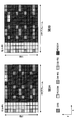
- CRS will be described with reference to FIG.
- cell #A shown in FIG. 2A and cell #B shown in FIG. 2B (here, cell #A is a serving cell and cell #B is a cooperative cell ( Data is transmitted to the same mobile terminal device.
- JT-CoMP is applied, as shown in FIGS. 2A and 2B, when the CRS multiplexing positions are different from each other, the CRS collides with the data signal and the mobile terminal apparatus cannot receive the CRS accurately. there is a possibility.
- the CRS of the cell other than the serving cell (neighboring cell (neighboring cell that can become a cooperative cell)) is used. It is necessary to notify the mobile terminal apparatus of the multiple positions. Therefore, the radio base station apparatus of the serving cell notifies the mobile terminal apparatus of CRS multiplexing positions of cells other than the serving cell as demodulation information.
- the radio base station apparatus of cell #A notifies the mobile terminal apparatus of CRS multiplexing position information of cell #B, which is an adjacent cell.
- the data signal is not multiplexed at the CRS multiplexing position of the cell #B so that the data signal of the cell #A does not collide.
- the CRS multiplexing position of cell #B means the PDSCH muting pattern of cell #A. Note that the CRS multiplexing position of the adjacent cell can be obtained from the shift amount by calculating the shift amount from the cell ID.
- the mobile terminal apparatus notifies the mobile terminal apparatus of the PDSCH muting pattern of the serving cell so that the CRS does not collide with the data signal.
- the serving cell is the cell #A
- the mobile terminal apparatus is notified of the PDSCH muting pattern (the CRS multiple position of the cell #B) shown in FIG. 2A
- the serving cell is the cell #B
- the mobile terminal apparatus is notified of the PDSCH muting pattern (CRS multiplexing position of cell #A) shown in 2B.
- DCS-CoMP the same mobile terminal apparatus from any one of a plurality of cells, for example, from any one of the cell #A shown in FIG. 3A and the cell #B shown in FIG. 3B Send data to.
- data is transmitted from a single cell.
- PDSCH need not be muted (no transmission) as in JT-CoMP (FIGS. 3A and 3B).
- a CoMP cell CoMP transmission can be applied to the mobile terminal device
- the following four methods can be cited as a method for notifying this pattern information (PDSCH muting pattern or CRS multiple pattern).
- This method is a method of notifying a bit map indicating a subcarrier position as a muting pattern.
- bitmap information is included in DCI (Downlink Control Information) and dynamically notified.
- the mobile terminal apparatus has a table shown in FIG. 4 (a table in which bitmap information included in DCI is associated with a muting pattern), and recognizes the muting pattern from the bitmap information notified by DCI.
- the data signal is demodulated using resources other than the muting pattern.
- the table shown in FIG. 4 is obtained by associating the bitmap information included in the DCI with the muting pattern.
- the bitmap “00000” is “no muting” and the bitmap “00001” is “serving cell.
- Bitmap “00010” is “Serving cell shift + 2 only”, Bitmap “00100” is “Serving cell shift + 3 only”, and Bitmap “11111” is “Serving cell shift + 1”. / + 2 / + 3 / + 4 / + 5 ".
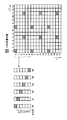
- This bitmap shows the subcarrier positions shown in FIG. In FIG.
- serving cell represents the muting pattern of cell ID # 0
- serving cell shift + 1 represents the muting pattern of cell ID # 1
- serving cell shift + 2 represents the muting pattern of cell ID # 2.
- serving cell shift + 3 represents the muting pattern of the cell ID # 3.
- This method is a method of notifying a bit map indicating a subcarrier position as a CRS multiplex pattern.
- bitmap information is included in DCI (Downlink Control Information) and dynamically notified.
- the mobile terminal apparatus has a table shown in FIG. 6 (a table in which bitmap information included in DCI and a CRS multiplexing pattern are associated), and recognizes the CRS multiplexing pattern from the bitmap information notified by DCI.
- the data signal is demodulated using resources other than the CRS multiplexing position.
- the table shown in FIG. 6 is obtained by associating the bitmap information included in the DCI with the CRS multiplexing pattern.
- the bitmap “00000” is “same as the serving cell”, and the bitmap “00001” is “the serving cell.
- Bitmap “00010” is “Serving cell shift + 2 only”, Bitmap “00100” is “Serving cell shift + 3 only”, and Bitmap “11111” is “Serving cell shift + 1”. / + 2 / + 3 / + 4 / + 5 ".
- This bitmap shows the subcarrier positions shown in FIG. In FIG.
- serving cell represents the CRS multiplexing pattern of the cell ID # 0
- serving cell shift + 1 represents the CRS multiplexing pattern of the cell ID # 1
- serving cell shift +2 represents the CRS multiplexing pattern of the cell ID # 2.
- serving cell shift + 3 represents the CRS multiplexing pattern of cell ID # 3.
- FIG. 6 is an example, and the present invention is not limited to this. 6 and 7 show the case of one antenna, this method can be applied to the case of two or more antennas.
- This method is a method of notifying downlink control information indicating a muting pattern as a muting pattern.
- a bit indicating a muting pattern is dynamically included in DCI.
- the downlink control information and the muting pattern are associated with each other.
- the mobile terminal apparatus has the table shown in FIG. 8 (a table in which bits included in DCI and muting patterns are associated), recognizes the muting pattern from the bits notified by DCI, and muting pattern.
- the data signal is demodulated using resources other than.
- the table shown in FIG. 8 associates the bit included in the DCI with the muting pattern, the bit “00” is “no muting”, and the bit “01” is “serving cell shift + 1 only”. Bit “10” is “serving cell shift +2 only” and bit “11” is “serving cell shift + 1 / + 2”. For example, bit “01” represents the muting pattern of FIG. 2A, and bit “11” represents the muting pattern of FIG.
- the table shown in FIG. 8 is an example, and the present invention is not limited to this.
- This method is a method of notifying downlink control information indicating a CRS multiplexing pattern as a CRS multiplexing pattern.
- bits indicating a CRS multiplexing pattern are included in DCI and dynamically notified.
- the downlink control information and the CRS multiplexing pattern are associated with each other.
- the mobile terminal apparatus has the table shown in FIG. 10 (a table in which bits included in DCI and CRS multiplexing patterns are associated), recognizes the CRS multiplexing pattern from the bits notified by DCI, and determines the CRS multiplexing position.
- the data signal is demodulated using resources other than.
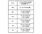
- the bits included in the DCI are associated with the CRS multiplexing pattern, the bit “000” is “same as the serving cell”, and the bit “001” is “serving cell shift + 1 only”.
- Bit “010” is “serving cell shift +2 only”, bit “011” is “serving cell shift +3 only”, bit “100” is “serving cell shift +4 only”, bit “ 101 "is” serving cell shift +5 only ".
- the bit “001” represents the CRS multiplexing pattern of FIG. 3B
- the bit “010” represents the CRS multiplexing pattern of FIG. Note that the table shown in FIG. 10 is an example, and the present invention is not limited to this.
- This method is a method of notifying a muting pattern by cell identification information of a CoMP cell transmitted by higher layer signaling and downlink control information corresponding to the information of the CoMP cell (information on a cell to be muted).
- downlink control information and CoMP cell information are associated with each other.
- the mobile terminal apparatus has a table shown in FIG. 12 (a table in which bits included in DCI and CoMP cell information are associated), and information on CoMP cells and higher layer signaling are transmitted from bits notified by DCI.
- a muting pattern is obtained from the notified cell identification information (cell ID) of the CoMP cell, and a data signal is demodulated using resources other than the muting pattern.
- the radio base station apparatus notifies the mobile terminal apparatus of the cell ID of a CoMP cell (a cell to which CoMP transmission may be applied) by higher layer signaling. For example, when the CoMP cells are cell #A and cell #B, the radio base station apparatus notifies the mobile terminal apparatus of cell ID No. 7 of cell #A and cell ID No. 8 of cell #B.
- the radio base station apparatus notifies CoMP cell information to the mobile terminal apparatus by DCI. For example, the radio base station apparatus notifies the mobile terminal apparatus of DCI bit “10” indicating “only shift of CoMP cell #B” as CoMP cell information.
- a muting pattern is obtained from the cell ID number and the information of the CoMP cell.
- Mod 6 of the cell ID number of cell #B is calculated to calculate a shift amount 2 (residue calculation), thereby obtaining a muting pattern (serving cell shift + 2).
- the table and cell ID number shown in FIG. 12 are examples, and the present invention is not limited to this.
- This method is a method of notifying the CRS multiplexing pattern by the cell identification information of the CoMP cell transmitted by higher layer signaling and the downlink control information corresponding to the information of the CoMP cell (information on the cell of the CRS multiplexing pattern). .
- downlink control information and CoMP cell information are associated with each other.
- the mobile terminal apparatus has a table shown in FIG. 13 (a table in which bits included in DCI are associated with CoMP cell information), and information on CoMP cells and higher layer signaling are transmitted from bits notified by DCI.
- a CRS multiplexing pattern is obtained from the notified cell identification information (cell ID) of the CoMP cell, and a data signal is demodulated using resources other than the CRS multiplexing position.
- the radio base station apparatus notifies the mobile terminal apparatus of the cell ID of a CoMP cell (a cell to which CoMP transmission may be applied) by higher layer signaling. For example, when the CoMP cells are cell #A and cell #B, the radio base station apparatus notifies the mobile terminal apparatus of cell ID No. 7 of cell #A and cell ID No. 8 of cell #B.
- the radio base station apparatus notifies CoMP cell information to the mobile terminal apparatus by DCI. For example, the radio base station apparatus notifies the mobile terminal apparatus of DCI bit “10” indicating “only shift of CoMP cell #B” as CoMP cell information.
- a CRS multiplexing pattern is obtained from the cell ID number and CoMP cell information.
- Mod 6 of the cell ID number of cell #B is calculated to calculate a shift amount 2 (residue calculation), thereby obtaining a CRS multiplexing pattern (serving cell shift + 2).
- the table and the cell ID number shown in FIG. 13 are examples, and the present invention is not limited to this.
- This method is a method of notifying the muting pattern by higher layer signaling (for example, RRC signaling).
- the muting pattern is notified semi-statically.
- the muting pattern notified by higher layer signaling may be bitmap information used in the first method or bit information used in the second method.
- the muting pattern may be static.
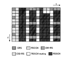
- the muting pattern is static, as shown in FIG. 15, no data signal is assigned to the mobile terminal apparatus that receives CoMP for the symbol (X) in which the CRS is multiplexed in the PDSCH region. That is, for a mobile terminal device that receives CoMP, the pattern of all symbols (X) in which CRS is multiplexed in the CoMP cell is a muting pattern.
- the CRS multiplexing pattern is notified by higher layer signaling (for example, RRC signaling).
- the CRS multiplexing pattern is notified semi-statically.
- the CRS multiplexing pattern notified by higher layer signaling may be the bitmap information used in the first method-2 or the bit information used in the second method-2.
- the CRS multiplexing pattern may be static.
- the CRS multiplexing pattern is static, as shown in FIG. 14, no data signal is assigned to the mobile terminal apparatus that receives CoMP for the symbol (X) in which the CRS is multiplexed in the PDSCH region. That is, for the mobile terminal apparatus that receives CoMP, the pattern of all symbols (X) in which CRS is multiplexed in the CoMP cell is the CRS multiplexing pattern.
- PDCCH may be multiplexed at different positions for each cell. Therefore, when applying JP-CoMP, it is considered that the data signal cannot be accurately demodulated in the mobile terminal apparatus. It is done.
- the PDCCH symbol length of the serving cell (cell #A: FIG. 15A) and the adjacent cell (cell #B: FIG. 15B). ) May have different PDCCH symbol lengths.
- JP-CoMP when JP-CoMP is applied, it is necessary to perform data transmission to a mobile terminal apparatus that performs CoMP reception in accordance with a cell having a long PDCCH symbol length.
- the mobile terminal apparatus that receives CoMP receives a cell other than the serving cell.
- the radio base station apparatus of the serving cell notifies the mobile terminal apparatus of the PDCCH length of cells other than the serving cell as demodulation information.
- the PDSCH when receiving the information on the PDCCH length, the PDSCH is multiplexed from the PDCCH length + 1 OFDM symbol. Therefore, the PDSCH multiplexing start position may be used as demodulation information instead of the PDCCH length. .
- the following two methods can be cited as the method of notifying the PDSCH multiple start position information.
- This method is a method of notifying downlink control information indicating the multiplexing start position of PDSCH.
- a bit indicating the multiplexing start position of PDSCH is included in DCI and dynamically notified.
- downlink control information and PDSCH multiplexing start position are associated with each other.
- the mobile terminal apparatus has the table shown in FIG. 16 (a table in which the bits included in DCI and the multiplexing start position of PDSCH are associated), and recognizes the multiplexing start position of PDSCH from the bits notified by DCI.
- the data signal is demodulated from the multiplexing start position.
- the table shown in FIG. 16 associates bits included in DCI with the PDSCH multiplexing start position, and bit “00” is “first symbol” and bit “01” is “second symbol”. Bit “10” is the “third symbol”, and bit “11” is the “fourth symbol”. For example, bit “10” represents the multiplexing start position (third symbol) of PDSCH in FIG. Note that the table shown in FIG. 16 is an example, and the present invention is not limited to this.
- This method is a method of notifying the PDSCH multiplexing start position by higher layer signaling (for example, RRC signaling).
- the PDSCH multiplexing start position is notified semi-statically.
- the PDSCH multiplexing start position notified by higher layer signaling may be bit information used in the fifth method.
- the PDSCH multiplexing start position may be static.
- the multiplexing start position is always fixed (for example, the fourth symbol).
- the radio base station apparatus determines whether the PDCCH length of the serving cell is shorter than the PDCCH length of the neighboring cell, and the PDCCH length of the serving cell is larger than the PDCCH length of the neighboring cell. Is shorter, the PDSCH multiplexing start position is determined in consideration of the PDCCH length of the adjacent cell, and the multiplexing start position is notified to the mobile terminal apparatus. For example, when the PDCCH length of the serving cell is shorter than the PDCCH length of the neighboring cell, the radio base station apparatus sets the longest PDCCH length + 1 symbol among the PDCCH lengths of the neighboring cell as the PDSCH multiplexing start position. Therefore, when the PDCCH length is a maximum of 3 symbols, the PDSCH multiplexing start position is a maximum of 4 symbols.
- the demodulation information is information for supporting the demodulation of the data signal in the mobile terminal apparatus.
- the CRS of the cells other than the serving cell is used.
- the demodulation information is information on the PDCCH symbol length or the PDSCH multiplexing start position.
- the demodulation information is information on CRS multiplexing positions of cells other than the serving cell, and information on the PDCCH symbol length or PDSCH multiplexing start position.
- data signal demodulation information in the mobile terminal apparatus is transmitted to the mobile terminal apparatus that receives cooperative multipoint reception, and the mobile terminal apparatus uses the demodulation information. Is used to demodulate the data signal received by cooperative multipoint, and therefore, when cooperative multipoint transmission, particularly, JP-CoMP is applied, the data signal can be accurately demodulated by the mobile terminal apparatus.
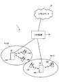
- FIG. 18 is a diagram for explaining the configuration of the radio communication system 1 including the mobile terminal apparatus 10 and the radio base station apparatus 20 according to the present invention.
- the wireless communication system 1 illustrated in FIG. 18 is a system including, for example, an LTE system or SUPER 3G.
- the mobile communication system 1 may be called IMT-Advanced or 4G.
- the radio communication system 1 includes radio base station apparatuses 20A and 20B and a plurality of mobile terminal apparatuses 10A and 10B communicating with the radio base station apparatuses 20A and 20B.
- the radio base station apparatuses 20 ⁇ / b> A and 20 ⁇ / b> B are each connected to a higher station apparatus 30, and the higher station apparatus 30 is connected to a core network 40.
- the mobile terminal apparatuses 10A and 10B communicate with the radio base station apparatus 20A in the cell C1, and communicate with the radio base station apparatus 20B in the cell C2.
- the upper station device 30 includes, for example, an access gateway device, a radio network controller (RNC), a mobility management entity (MME), and the like, but is not limited thereto.
- RNC radio network controller
- MME mobility management entity
- each mobile terminal device (10A, 10B) has the same configuration, function, and state, the following description will be given as the mobile terminal device 10 unless otherwise noted.
- the mobile terminal device 10 is in radio communication with the radio base station devices 20A and 20B, but more generally, user equipment (UE) including both the mobile terminal device and the fixed terminal device. It's okay.
- UE user equipment
- OFDMA orthogonal frequency division multiple access
- SC-FDMA single carrier-frequency division multiple access
- OFDMA is a multi-carrier transmission scheme that performs communication by dividing a frequency band into a plurality of narrow frequency bands (subcarriers) and mapping data to each subcarrier.
- SC-FDMA is a single carrier transmission method that reduces interference between terminals by dividing a system band into bands each consisting of one or continuous resource blocks for each terminal, and a plurality of terminals using different bands. .
- the downlink communication channel includes PDSCH as a downlink data channel shared by the mobile terminal apparatuses 10A and 10B, and downlink L1 / L2 control channels (PDCCH, PCFICH, PHICH). Transmission data and higher control information are transmitted by the PDSCH. PDSCH and PUSCH scheduling information and the like are transmitted by the PDCCH.
- the number of OFDM symbols used for PDCCH is transmitted by PCFICH (Physical Control Format Indicator Channel).
- the HARQ ACK / NACK for PUSCH is transmitted by PHICH (Physical Hybrid-ARQ Indicator Channel).
- the uplink communication channel has PUSCH (Physical Uplink Shared Channel) as an uplink data channel shared by each mobile terminal apparatus and PUCCH (Physical Uplink Control Channel) as an uplink control channel. Transmission data and higher control information are transmitted by this PUSCH. Further, downlink channel quality information (CQI), ACK / NACK, and the like are transmitted by PUCCH.
- PUSCH Physical Uplink Shared Channel
- PUCCH Physical Uplink Control Channel
- the radio base station apparatus 20 includes a transmission / reception antenna 201, an amplifier unit 202, a transmission / reception unit (notification unit) 203, a baseband signal processing unit 204, a call processing unit 205, and a transmission path interface 206. Transmission data transmitted from the radio base station apparatus 20 to the mobile terminal apparatus via the downlink is input from the higher station apparatus 30 to the baseband signal processing unit 204 via the transmission path interface 206.
- the downlink data channel signal is transmitted from the RCP layer, such as PDCP layer processing, transmission data division / combination, RLC (Radio Link Control) retransmission control transmission processing, and MAC (Medium Access).
- RCP layer such as PDCP layer processing, transmission data division / combination, RLC (Radio Link Control) retransmission control transmission processing, and MAC (Medium Access).
- Control Retransmission control, for example, HARQ transmission processing, scheduling, transmission format selection, channel coding, inverse fast Fourier transform (IFFT) processing, and precoding processing are performed.
- transmission processing such as channel coding and inverse fast Fourier transform is performed on the signal of the physical downlink control channel, which is the downlink control channel.
- the baseband signal processing unit 204 notifies the mobile terminal device 10 connected to the same cell of the control information for wireless communication between the mobile terminal device 10 and the radio base station device 20 to the mobile terminal device 10 connected to the same cell.
- the information for communication in the cell includes, for example, system bandwidth in uplink or downlink, and root sequence identification information (Root Sequence) for generating a random access preamble signal in PRACH (Physical Random Access Channel). Index) etc. are included.
- the transmission / reception unit 203 converts the baseband signal output from the baseband signal processing unit 204 into a radio frequency band.
- the amplifier unit 202 amplifies the radio frequency signal subjected to frequency conversion and outputs the amplified signal to the transmission / reception antenna 201.
- the transmission / reception part 203 comprises the receiving part which receives the information of the phase difference between several cells, and the uplink signal containing PMI, and the transmission part which carries out cooperative multipoint transmission of the transmission signal.
- a radio frequency signal received by the transmission / reception antenna 201 is amplified by the amplifier section 202, and frequency-converted by the transmission / reception section 203. It is converted into a band signal and input to the baseband signal processing unit 204.
- the baseband signal processing unit 204 performs FFT processing, IDFT processing, error correction decoding, MAC retransmission control reception processing, RLC layer, PDCP layer reception processing on transmission data included in the baseband signal received in the uplink I do.
- the decoded signal is transferred to the higher station apparatus 30 via the transmission path interface 206.
- the call processing unit 205 performs call processing such as communication channel setting and release, state management of the radio base station apparatus 20, and radio resource management.
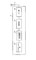
- Each functional block in FIG. 20 is mainly processing contents of the baseband processing unit. Also, the functional blocks shown in FIG. 20 are simplified for the purpose of explaining the present invention, and the configuration normally provided in the baseband processing unit is provided.
- the radio base station apparatus 20 includes a CRS allocation unit 211, a DM-RS allocation unit 212, a CSI-RS allocation unit 213, a demodulation information generation unit 214, and a downlink control signal generation unit 215. And a transmission / reception unit 203.
- the radio base station apparatus 20 When applying the CoMP transmission, the radio base station apparatus 20 generates data signal demodulation information in the mobile terminal apparatus and transmits the demodulation information to the mobile terminal apparatus that receives the CoMP.
- the CRS allocation unit 211 arranges the CRS in the CRS transmission resource in the resource block of each subframe.
- the CRS is arranged in the corresponding resource element on the resource block according to the CRS arrangement pattern in which the CRS arrangement position is determined so that the CRS does not overlap with other control signals.
- a DM-RS (Demodulation-Reference Signal) allocation unit 212 arranges a DM-RS in a DM-RS transmission resource in a resource block of each subframe.
- a CSI-RS (Channel State Information-Reference Signal) Demodulation-Reference Signal (allocating unit) 213 arranges a CSI-RS in a corresponding subframe in a radio frame in a CSI-RS transmission cycle (for example, 10 ms or 8 ms).
- Demodulation information generation section 214 generates data signal demodulation information in the mobile terminal apparatus, and outputs the demodulation information to downlink control signal 215.
- this demodulation information refers to PDSCH muting pattern, CRS multiplexing pattern, and PDSCH start position information.
- the demodulation information generation unit 214 may generate a PDSCH muting pattern or a CRS multiplexing pattern (pattern information) as demodulation information, and indicates a subcarrier position regarding the PDSCH muting pattern or the CRS multiplexing pattern (pattern information).
- Bitmap information may be generated, or CoMP cell information (information on cells to be muted or CRS multiple patterns) regarding PDSCH muting patterns and CRS multiple patterns (pattern information) may be generated.
- the demodulation information generation unit 214 generates bitmap information indicating the subcarrier position regarding the PDSCH muting pattern as the demodulation information in the first method-1, and the demodulation information in the second method-1.
- PDSCH muting pattern is generated as follows.
- CoMP cell information related to the PDSCH muting pattern is generated.
- the demodulation information generation unit 214 generates bitmap information indicating the subcarrier position related to the CRS multiplex pattern as the demodulation information in the first method-2, and as the demodulation information in the second method-2.
- a CRS multiplex pattern is generated, and in the third method-2, CoMP cell information related to the CRS multiplex pattern is generated.
- the demodulation information generation unit 214 generates PDSCH multiplexing start position information as demodulation information.
- the downlink control signal generation unit 215 generates a downlink control signal by including information on the PDSCH muting pattern, the CRS multiplexing pattern, and the PDSCH start position in the DCI.
- the downlink control signal generation unit 215 generates a downlink control signal by including a bit map indicating a subcarrier position related to the PDSCH muting pattern in the DCI.
- the downlink control signal generation unit 215 generates a downlink control signal.
- the bit corresponding to the coding pattern is included in the DCI, and the bit corresponding to the information of the CoMP cell is included in the DCI to generate the downlink control signal.
- the downlink control signal generation unit 215 generates a downlink control signal by including a bit map indicating the subcarrier position related to the CRS multiplexing pattern in the DCI, and in the second method-2, the downlink control signal is generated.
- the downlink control signal is generated by including bits corresponding to the multiplexed pattern in the DCI
- the downlink control signal is generated by including bits corresponding to the information of the CoMP cell in the DCI.
- the downlink control signal generation unit 215 outputs the generated downlink control signal (PDCCH signal) to the transmission / reception unit 203.
- downlink control signal generation section 215 generates a downlink control signal by including the PDSCH multiplexing start position in DCI.
- the transmission / reception unit 203 maps the CRS, DM-RS, CSI-RS, and downlink control signal to resources and transmits them to the mobile terminal apparatus 10 as downlink signals.
- the downlink signal includes a signal normally transmitted as a downlink signal in addition to the above signal.
- the radio base station apparatus 20 may transmit demodulation information to the mobile terminal apparatus 10 by higher layer signaling.
- the radio base station apparatus 20 transmits the cell ID of the CoMP cell to the mobile terminal apparatus 10 as demodulation information
- the demodulation information And the PDSCH muting pattern is transmitted to the mobile terminal apparatus.
- the CRS multiplexed pattern is transmitted to the mobile terminal apparatus as demodulation information.
- the radio base station apparatus 20 transmits the PDSCH multiplexing start position to the mobile terminal apparatus 10 as demodulation information.
- the mobile terminal apparatus 10 includes a transmission / reception antenna 101, an amplifier unit 102, a transmission / reception unit (reception unit) 103, a baseband signal processing unit 104, and an application unit 105.
- the mobile terminal apparatus receives data signal demodulation information from the serving cell, and demodulates the CoMP received data signal using the demodulation information.
- a radio frequency signal received by the transmission / reception antenna 101 is amplified by the amplifier unit 102, frequency-converted by the transmission / reception unit 103, and converted into a baseband signal.
- the baseband signal is subjected to FFT processing, error correction decoding, retransmission control reception processing, and the like by the baseband signal processing unit 104.
- downlink transmission data is transferred to the application unit 105.
- the application unit 105 performs processing related to layers higher than the physical layer and the MAC layer. Also, the broadcast information in the downlink data is also transferred to the application unit 105.
- uplink transmission data is input from the application unit 105 to the baseband signal processing unit 104.
- the baseband signal processing unit 104 performs mapping processing, retransmission control (HARQ) transmission processing, channel coding, DFT processing, and IFFT processing.
- the transmission / reception unit 103 converts the baseband signal output from the baseband signal processing unit 104 into a radio frequency band. Thereafter, the signal is amplified by the amplifier unit 102 and transmitted from the transmission / reception antenna 101.
- HARQ retransmission control
- Each functional block in FIG. 22 is mainly processing contents of the baseband processing unit. Further, the functional blocks shown in FIG. 22 are simplified for the purpose of explaining the present invention, and the configuration normally provided in the baseband processing unit is provided.
- the mobile terminal apparatus 10 includes a transmission / reception unit 103, an acquisition unit 111, a measurement unit 112, and a user data demodulation unit 113.
- the transmission / reception unit 103 receives a downlink control signal (PDCCH signal) transmitted from the radio base station apparatus 20, and receives a data channel signal (PDSCH signal: user data).
- the transmission / reception unit 103 outputs the downlink control signal and the control information subjected to higher layer signaling to the acquisition unit 111. Further, the transmitting / receiving unit 103 outputs user data and DM-RS to the user data demodulating unit 113 and outputs CRS and CSI-RS to the measuring unit 12.
- the acquisition unit 111 analyzes the downlink control signal received by the transmission / reception unit 103 and acquires demodulation information.
- the acquisition unit 111 has the table shown in FIG.
- the acquisition part 111 calculates
- the acquisition unit 111 has the table shown in FIG. Then, the acquisition unit 111 refers to the table shown in FIG. 6 and obtains the CRS multiplex pattern from the bit map indicating the subcarrier position related to the CRS multiplex pattern included in the DCI of the downlink control signal.
- the acquisition unit 111 has the table shown in FIG. And the acquisition part 111 calculates
- the acquisition unit 111 has the table shown in FIG. And the acquisition part 111 calculates
- the acquisition unit 111 has the table shown in FIG. Then, the acquisition unit 111 refers to the table shown in FIG. 12 and acquires CoMP cell information (information regarding cells to be muted) regarding the PDSCH muting pattern. On the other hand, the acquisition unit 111 acquires the CoMP cell ID number sent by higher layer signaling, calculates the CRS shift amount from the CoMP cell information and the CoMP cell ID number, and based on this shift amount, PDSCH Find the muting pattern. Therefore, in the third method-1, the acquisition unit 111 constitutes a pattern generation unit that generates a muting pattern. In the third method-2, the acquisition unit 111 has the table shown in FIG. Then, the acquisition unit 111 refers to the table shown in FIG.
- the acquisition unit 111 configures a pattern generation unit that generates a CRS multiple pattern.
- the acquiring unit 111 acquires the PDSCH muting pattern sent by higher layer signaling (semi-static). Further, when the PDSCH muting pattern is statically notified, the acquiring unit 111 acquires the PDSCH muting pattern as shown in FIG. 14 sent from the radio base station apparatus at the start of communication or the like.
- the acquiring unit 111 acquires a CRS multiplexing pattern sent by higher layer signaling (semi-static). When notifying statically the CRS multiplex pattern, the acquisition unit 111 acquires the CRS multiplex pattern as shown in FIG. 14 sent from the radio base station apparatus at the start of communication or the like.
- the acquisition unit 111 has the table shown in FIG. And the acquisition part 111 calculates
- the acquisition unit 111 acquires the multiplex start position of the PDSCH sent by higher layer signaling (semi-static). In addition, when statically reporting the PDSCH multiplexing start position, the acquisition unit 111 acquires the PDSCH multiplexing start position transmitted from the radio base station apparatus at the start of communication or the like.
- the acquisition unit 111 outputs the PDSCH muting pattern, the CRS multiplexing pattern, and the PDSCH multiplexing start position information, which are demodulation information, to the user data demodulation unit 113.
- the measuring unit 112 identifies a CSI-RS resource in which CSI-RS is multiplexed on the resource block, and performs channel estimation using the CSI-RS.
- the user data demodulation unit 113 demodulates user data received via the transmission / reception unit 103. At this time, the user data demodulator 113 demodulates the user data using the DM-RS specific to the user.
- the user data demodulation unit 113 uses the pattern information (PDSCH muting pattern, CRS multiplexing pattern) from the acquisition unit 111 to determine the muting resource and the CRS multiplexing position from the target of the demodulation process. And demodulate user data. Further, in the fifth method and the sixth method, the user data demodulation unit 113 uses the PDSCH multiplexing start position from the acquisition unit 111 and demodulates the user data from the multiplexing start position.
- the wireless communication system when applying CoMP transmission, data signal demodulation information in the mobile terminal apparatus is transmitted to the mobile terminal apparatus that receives CoMP, and the mobile terminal apparatus performs demodulation. Since the data signal received by CoMP is demodulated using information, particularly when JP-CoMP is applied, the data signal can be accurately demodulated by the mobile terminal apparatus.
- the demodulation information generation unit 214 generates bitmap information indicating subcarrier positions related to the PDSCH muting pattern as demodulation information.
- the downlink control signal generation unit 215 generates a downlink control signal by including in the DCI a bitmap indicating the subcarrier position related to the PDSCH muting pattern. The radio base station apparatus transmits this downlink control signal to the mobile terminal apparatus.
- the acquisition unit 111 refers to the table shown in FIG. 4 and obtains the muting pattern from the bit map indicating the subcarrier position related to the PDSCH muting pattern included in the DCI of the downlink control signal.
- the user data demodulator 113 demodulates the user data using the muting pattern.
- demodulation information generation section 214 In the radio base station apparatus, demodulation information generation section 214 generates bitmap information indicating subcarrier positions related to the CRS multiplex pattern as demodulation information. Next, the downlink control signal generation unit 215 generates a downlink control signal by including in the DCI a bitmap indicating the subcarrier position related to the CRS multiplexing pattern. The radio base station apparatus transmits this downlink control signal to the mobile terminal apparatus.
- the acquisition unit 111 refers to the table shown in FIG. 6 and obtains the CRS multiplexing pattern from the bitmap indicating the subcarrier position related to the CRS multiplexing pattern included in the DCI of the downlink control signal.
- the user data demodulator 113 demodulates the user data using the CRS multiplexing pattern.
- the demodulation information generation unit 214 In the radio base station apparatus, the demodulation information generation unit 214 generates a PDSCH muting pattern as the demodulation information. Next, the downlink control signal generation section 215 generates a downlink control signal by including bits indicating the PDSCH muting pattern in the DCI. The radio base station apparatus transmits this downlink control signal to the mobile terminal apparatus.
- the acquisition unit 111 refers to the table shown in FIG. 8 to obtain the PDSCH muting pattern included in the DCI of the downlink control signal.
- the user data demodulator 113 demodulates the user data using the muting pattern.
- the demodulation information generation unit 214 In the radio base station apparatus, the demodulation information generation unit 214 generates a CRS multiplex pattern as the demodulation information. Next, the downlink control signal generation unit 215 generates a downlink control signal by including bits indicating the CRS multiplexing pattern in the DCI. The radio base station apparatus transmits this downlink control signal to the mobile terminal apparatus.
- the acquisition unit 111 refers to the table shown in FIG.
- the user data demodulator 113 demodulates the user data using the CRS multiplexing pattern.
- demodulation information generation section 214 In the radio base station apparatus, demodulation information generation section 214 generates CoMP cell information related to the PDSCH muting pattern as demodulation information. Next, the downlink control signal generation section 215 generates a downlink control signal by including bits corresponding to CoMP cell information in DCI. The radio base station apparatus transmits this downlink control signal to the mobile terminal apparatus. Further, the radio base station apparatus transmits the cell ID of the CoMP cell to the mobile terminal apparatus as demodulation information by higher layer signaling.
- the acquisition unit 111 refers to the table shown in FIG. 12 and acquires CoMP cell information (information on the cell to be muted) regarding the PDSCH muting pattern. On the other hand, the acquisition unit 111 acquires the CoMP cell ID number sent by higher layer signaling, calculates the CRS shift amount from the CoMP cell information and the CoMP cell ID number, and based on this shift amount, PDSCH Find the muting pattern. Next, the user data demodulator 113 demodulates the user data using the muting pattern.
- demodulation information generation section 214 In the radio base station apparatus, demodulation information generation section 214 generates CoMP cell information related to the CRS multiplexing pattern as demodulation information. Next, the downlink control signal generation section 215 generates a downlink control signal by including bits corresponding to CoMP cell information in DCI. The radio base station apparatus transmits this downlink control signal to the mobile terminal apparatus. Further, the radio base station apparatus transmits the cell ID of the CoMP cell to the mobile terminal apparatus as demodulation information by higher layer signaling.
- the acquisition unit 111 refers to the table shown in FIG. 13 and acquires CoMP cell information (information about CRS multiple pattern cells) related to the CRS multiple pattern.
- the acquiring unit 111 acquires the CoMP cell ID number sent by higher layer signaling, calculates the CRS shift amount from the CoMP cell information and the CoMP cell ID number, and based on this shift amount, the CRS. Find multiple patterns.
- the user data demodulator 113 demodulates the user data using the CRS multiplexing pattern.
- the radio base station apparatus transmits a PDSCH muting pattern to the mobile terminal apparatus as demodulation information by higher layer signaling (semi-static).
- the radio base station apparatus transmits a PDSCH muting pattern as shown in FIG. 14 to the mobile terminal apparatus at the start of communication or the like.
- the acquisition unit 111 acquires the PDSCH muting pattern sent by higher layer signaling (semi-static).
- the user data demodulator 113 demodulates the user data using the muting pattern.
- the acquiring unit 111 demodulates the user data using the PDSCH muting pattern as shown in FIG. 14 sent at the start of communication or the like.
- the radio base station apparatus transmits a CRS multiplexing pattern to the mobile terminal apparatus as demodulation information by higher layer signaling (semi-static).
- the radio base station apparatus transmits a CRS multiplex pattern as shown in FIG. 14 to the mobile terminal apparatus when communication is started.
- the acquisition unit 111 acquires a CRS multiplexing pattern sent by higher layer signaling (semi-static).
- the user data demodulator 113 demodulates the user data using the CRS multiplexing pattern.
- the acquiring unit 111 demodulates user data using the CRS multiplex pattern as shown in FIG. 14 transmitted at the start of communication or the like.
- the demodulation information generation unit 214 In the radio base station apparatus, the demodulation information generation unit 214 generates PDSCH multiplexing start position information as demodulation information as demodulation information.
- the downlink control signal generation section 215 includes a bit indicating the PDSCH multiplexing start position in the DCI to generate a downlink control signal. The radio base station apparatus transmits this downlink control signal to the mobile terminal apparatus.
- the acquisition unit 111 refers to the table shown in FIG. 16 to obtain the PDSCH multiplexing start position included in the DCI of the downlink control signal.
- user data demodulation section 113 demodulates user data using the PDSCH multiplexing start position.
- the radio base station apparatus transmits the PDSCH multiplexing start position to the mobile terminal apparatus as demodulation information by higher layer signaling (semi-static).
- the radio base station apparatus transmits the PDSCH multiplexing start position to the mobile terminal apparatus when communication is started.
- the acquisition unit 111 acquires the multiplex start position of the PDSCH sent by higher layer signaling (semi-static).
- user data demodulation section 113 demodulates user data using the PDSCH multiplexing start position.
- the acquiring unit 111 demodulates the user data using the PDSCH multiplexing start position transmitted at the start of communication or the like.
Landscapes
- Engineering & Computer Science (AREA)
- Signal Processing (AREA)
- Computer Networks & Wireless Communication (AREA)
- Mobile Radio Communication Systems (AREA)
Abstract
Description
この方法は、サブキャリア位置を示すビットマップをミューティングパターンとして通知する方法である。この方法においては、ビットマップ情報をDCI(Downlink Control Information)に含めてダイナミックに通知する。移動端末装置は、図4に示すテーブル(DCIに含まれるビットマップ情報とミューティングパターンとが関連づけられたテーブル)を持っており、DCIで通知されたビットマップ情報からミューティングパターンを認識して、ミューティングパターン以外のリソースを用いてデータ信号を復調する。
この方法は、サブキャリア位置を示すビットマップをCRS多重パターンとして通知する方法である。この方法においては、ビットマップ情報をDCI(Downlink Control Information)に含めてダイナミックに通知する。移動端末装置は、図6に示すテーブル(DCIに含まれるビットマップ情報とCRS多重パターンとが関連づけられたテーブル)を持っており、DCIで通知されたビットマップ情報からCRS多重パターンを認識して、CRS多重位置以外のリソースを用いてデータ信号を復調する。
この方法は、ミューティングパターンを示す下り制御情報をミューティングパターンとして通知する方法である。この方法においては、ミューティングパターンを示すビットをDCIに含めてダイナミックに通知する。この場合、下り制御情報とミューティングパターンとが関連づけられている。移動端末装置は、図8に示すテーブル(DCIに含まれるビットとミューティングパターンとが関連づけられたテーブル)を持っており、DCIで通知されたビットからミューティングパターンを認識して、ミューティングパターン以外のリソースを用いてデータ信号を復調する。
この方法は、CRS多重パターンを示す下り制御情報をCRS多重パターンとして通知する方法である。この方法においては、CRS多重パターンを示すビットをDCIに含めてダイナミックに通知する。この場合、下り制御情報とCRS多重パターンとが関連づけられている。移動端末装置は、図10に示すテーブル(DCIに含まれるビットとCRS多重パターンとが関連づけられたテーブル)を持っており、DCIで通知されたビットからCRS多重パターンを認識して、CRS多重位置以外のリソースを用いてデータ信号を復調する。
この方法は、ハイヤレイヤシグナリングにより送信されるCoMPセルのセル識別情報と、このCoMPセルの情報(ミューティングするセルに関する情報)に対応する下り制御情報とでミューティングパターンを通知する方法である。この場合、下り制御情報とCoMPセルの情報とが関連づけられている。移動端末装置は、図12に示すテーブル(DCIに含まれるビットとCoMPセルの情報とが関連づけられたテーブル)を持っており、DCIで通知されたビットからCoMPセルの情報と、ハイヤレイヤシグナリングで通知されたCoMPセルのセル識別情報(セルID)とからミューティングパターンを求め、ミューティングパターン以外のリソースを用いてデータ信号を復調する。
この方法は、ハイヤレイヤシグナリングにより送信されるCoMPセルのセル識別情報と、このCoMPセルの情報(CRS多重パターンのセルに関する情報)に対応する下り制御情報とでCRS多重パターンを通知する方法である。この場合、下り制御情報とCoMPセルの情報とが関連づけられている。移動端末装置は、図13に示すテーブル(DCIに含まれるビットとCoMPセルの情報とが関連づけられたテーブル)を持っており、DCIで通知されたビットからCoMPセルの情報と、ハイヤレイヤシグナリングで通知されたCoMPセルのセル識別情報(セルID)とからCRS多重パターンを求め、CRS多重位置以外のリソースを用いてデータ信号を復調する。
この方法は、ミューティングパターンをハイヤレイヤシグナリング(例えば、RRCシグナリング)で通知する方法である。この方法においては、ミューティングパターンをセミスタティックに通知する。ハイヤレイヤシグナリングで通知するミューティングパターンは、上記第1方法で使用するビットマップ情報でも良く、上記第2方法で使用するビット情報でも良い。
この方法は、CRS多重パターンをハイヤレイヤシグナリング(例えば、RRCシグナリング)で通知する方法である。この方法においては、CRS多重パターンをセミスタティックに通知する。ハイヤレイヤシグナリングで通知するCRS多重パターンは、上記第1方法-2で使用するビットマップ情報でも良く、上記第2方法-2で使用するビット情報でも良い。
この方法は、PDSCHの多重開始位置を示す下り制御情報を通知する方法である。この方法においては、PDSCHの多重開始位置を示すビットをDCIに含めてダイナミックに通知する。この場合、下り制御情報とPDSCHの多重開始位置とが関連づけられている。移動端末装置は、図16に示すテーブル(DCIに含まれるビットとPDSCHの多重開始位置とが関連づけられたテーブル)を持っており、DCIで通知されたビットからPDSCHの多重開始位置を認識して、その多重開始位置からデータ信号を復調する。
この方法は、PDSCHの多重開始位置をハイヤレイヤシグナリング(例えば、RRCシグナリング)で通知する方法である。この方法においては、PDSCHの多重開始位置をセミスタティックに通知する。ハイヤレイヤシグナリングで通知するPDSCHの多重開始位置は、上記第5方法で使用するビット情報でも良い。
無線基地局装置において、復調用情報生成部214で、復調用情報としてPDSCHミューティングパターンに関するサブキャリア位置を示すビットマップ情報を生成する。次いで、下り制御信号生成部215で、PDSCHミューティングパターンに関するサブキャリア位置を示すビットマップをDCIに含めて下り制御信号を生成する。無線基地局装置は、この下り制御信号を移動端末装置に送信する。
無線基地局装置において、復調用情報生成部214で、復調用情報としてCRS多重パターンに関するサブキャリア位置を示すビットマップ情報を生成する。次いで、下り制御信号生成部215で、CRS多重パターンに関するサブキャリア位置を示すビットマップをDCIに含めて下り制御信号を生成する。無線基地局装置は、この下り制御信号を移動端末装置に送信する。
無線基地局装置において、復調用情報生成部214で、復調用情報としてPDSCHミューティングパターンを生成する。次いで、下り制御信号生成部215で、PDSCHミューティングパターンを示すビットをDCIに含めて下り制御信号を生成する。無線基地局装置は、この下り制御信号を移動端末装置に送信する。
無線基地局装置において、復調用情報生成部214で、復調用情報としてCRS多重パターンを生成する。次いで、下り制御信号生成部215で、CRS多重パターンを示すビットをDCIに含めて下り制御信号を生成する。無線基地局装置は、この下り制御信号を移動端末装置に送信する。
無線基地局装置において、復調用情報生成部214で、復調用情報としてPDSCHミューティングパターンに関するCoMPセルの情報を生成する。次いで、下り制御信号生成部215で、CoMPセルの情報に対応するビットをDCIに含めて下り制御信号を生成する。無線基地局装置は、この下り制御信号を移動端末装置に送信する。また、無線基地局装置は、ハイヤレイヤシグナリングで復調用情報としてCoMPセルのセルIDを移動端末装置に送信する。
無線基地局装置において、復調用情報生成部214で、復調用情報としてCRS多重パターンに関するCoMPセルの情報を生成する。次いで、下り制御信号生成部215で、CoMPセルの情報に対応するビットをDCIに含めて下り制御信号を生成する。無線基地局装置は、この下り制御信号を移動端末装置に送信する。また、無線基地局装置は、ハイヤレイヤシグナリングで復調用情報としてCoMPセルのセルIDを移動端末装置に送信する。
無線基地局装置は、ハイヤレイヤシグナリングで復調用情報としてPDSCHミューティングパターンを移動端末装置に送信する(セミスタティック)。また、スタティックにPDSCHミューティングパターンを通知する場合には、無線基地局装置は、通信開始時等に図14に示すようなPDSCHミューティングパターンを移動端末装置に送信する。
無線基地局装置は、ハイヤレイヤシグナリングで復調用情報としてCRS多重パターンを移動端末装置に送信する(セミスタティック)。また、スタティックにCRS多重パターンを通知する場合には、無線基地局装置は、通信開始時等に図14に示すようなCRS多重パターンを移動端末装置に送信する。
無線基地局装置において、復調用情報生成部214で、復調用情報として復調用情報としてPDSCHの多重開始位置情報を生成する。次いで、下り制御信号生成部215で、PDSCHの多重開始位置を示すビットをDCIに含めて下り制御信号を生成する。無線基地局装置は、この下り制御信号を移動端末装置に送信する。
無線基地局装置は、ハイヤレイヤシグナリングで復調用情報としてPDSCHの多重開始位置を移動端末装置に送信する(セミスタティック)。また、スタティックにPDSCHの多重開始位置を通知する場合には、無線基地局装置は、通信開始時等にPDSCHの多重開始位置を移動端末装置に送信する。
Claims (14)
- 協調マルチポイント送信を適用する際に、移動端末装置におけるデータ信号の復調用情報を生成する生成部と、前記復調用情報を協調マルチポイント受信する移動端末装置に送信する送信部と、を具備することを特徴とする無線基地局装置。
- 前記復調用情報は、サービングセルの物理下り共有チャネル信号のミューティングパターン又はセル固有参照信号の多重パターンを示すパターン情報であることを特徴とする請求項1記載の無線基地局装置。
- 前記パターン情報は、サブキャリア位置を示すビットマップで示されることを特徴とする請求項2記載の無線基地局装置。
- 下り制御情報(DCI)と前記パターン情報とが関連づけられており、前記下り制御情報により前記パターン情報を通知することを特徴とする請求項2記載の無線基地局装置。
- 下り制御情報(DCI)と協調マルチポイント送信を適用する可能性のあるCoMPセルのセル識別情報とが関連づけられており、ハイヤレイヤシグナリングにより送信される前記CoMPセルのセル識別情報と、前記CoMPセルの情報に対応する下り制御情報とでパターン情報を通知することを特徴とする請求項2記載の無線基地局装置。
- 前記パターン情報をハイヤレイヤシグナリングで通知することを特徴とする請求項2記載の無線基地局装置。
- 前記復調用情報は、物理下り共有チャネル信号の多重開始位置の情報であることを特徴とする請求項2記載の無線基地局装置。
- 物理下り共有チャネル信号の多重開始位置の情報を下り制御情報(DCI)で通知することを特徴とする請求項7記載の無線基地局装置。
- 物理下り共有チャネル信号の多重開始位置の情報をハイヤレイヤシグナリングで通知することを特徴とする請求項7記載の無線基地局装置。
- 協調マルチポイント送信を適用する際に、サービングセルからのデータ信号の復調用情報を受信する受信部と、前記復調用情報を用いて協調マルチポイント受信したデータ信号を復調する復調部と、を具備することを特徴とする移動端末装置。
- 下り制御情報からパターン情報を生成するパターン生成部をさらに具備することを特徴とする請求項10記載の移動端末装置。
- 前記パターン生成部は、協調マルチポイント送信を適用する可能性のあるCoMPセルのセル識別情報と、前記CoMPセルの情報に対応する下り制御情報とからパターン情報を生成することを特徴とする請求項11記載の移動端末装置。
- 無線基地局装置において、協調マルチポイント送信を適用する際に、移動端末装置におけるデータ信号の復調用情報を生成する工程と、前記復調用情報を協調マルチポイント受信する移動端末装置に送信する工程と、前記移動端末装置において、前記データ信号の復調用情報を受信する工程と、前記復調用情報を用いて協調マルチポイント受信したデータ信号を復調する工程と、を具備することを特徴とする無線通信方法。
- 協調マルチポイント送信を適用する際に、移動端末装置におけるデータ信号の復調用情報を生成する生成部、及び前記復調用情報を協調マルチポイント受信する移動端末装置に送信する送信部を有する無線基地局装置と、前記データ信号の復調用情報を受信する受信部、及び前記復調用情報を用いて協調マルチポイント受信したデータ信号を復調する復調部を有する移動端末装置と、を具備することを特徴とする無線通信システム。
Priority Applications (6)
| Application Number | Priority Date | Filing Date | Title |
|---|---|---|---|
| KR1020137031192A KR20140040135A (ko) | 2011-05-02 | 2012-04-24 | 무선기지국장치, 이동단말장치, 무선통신방법 및 무선통신시스템 |
| US14/114,570 US10064216B2 (en) | 2011-05-02 | 2012-04-24 | Radio base station apparatus, mobile terminal apparatus, radio communication method and radio communication system |
| AU2012251290A AU2012251290B2 (en) | 2011-05-02 | 2012-04-24 | Radio base station apparatus, mobile terminal apparatus, radio communication method and radio communication system |
| EP12779672.0A EP2706799B1 (en) | 2011-05-02 | 2012-04-24 | Wireless base station device, mobile terminal device, wireless communication method, and wireless communication system |
| CN201280021436.8A CN103503543B (zh) | 2011-05-02 | 2012-04-24 | 无线基站装置、移动终端装置、无线通信方法以及无线通信系统 |
| BR112013028121A BR112013028121A2 (pt) | 2011-05-02 | 2012-04-24 | aparelho de estação rádio base, aparelho de terminal móvel, método de comunicação de rádio e sistema de comunicação de rádio |
Applications Claiming Priority (2)
| Application Number | Priority Date | Filing Date | Title |
|---|---|---|---|
| JP2011-103071 | 2011-05-02 | ||
| JP2011103071A JP5437310B2 (ja) | 2011-05-02 | 2011-05-02 | 無線基地局装置、移動端末装置、無線通信方法及び無線通信システム |
Publications (1)
| Publication Number | Publication Date |
|---|---|
| WO2012150686A1 true WO2012150686A1 (ja) | 2012-11-08 |
Family
ID=47107875
Family Applications (1)
| Application Number | Title | Priority Date | Filing Date |
|---|---|---|---|
| PCT/JP2012/060981 Ceased WO2012150686A1 (ja) | 2011-05-02 | 2012-04-24 | 無線基地局装置、移動端末装置、無線通信方法及び無線通信システム |
Country Status (8)
| Country | Link |
|---|---|
| US (1) | US10064216B2 (ja) |
| EP (1) | EP2706799B1 (ja) |
| JP (1) | JP5437310B2 (ja) |
| KR (1) | KR20140040135A (ja) |
| CN (1) | CN103503543B (ja) |
| AU (1) | AU2012251290B2 (ja) |
| BR (1) | BR112013028121A2 (ja) |
| WO (1) | WO2012150686A1 (ja) |
Cited By (3)
| Publication number | Priority date | Publication date | Assignee | Title |
|---|---|---|---|---|
| WO2014115474A1 (ja) * | 2013-01-24 | 2014-07-31 | 株式会社Nttドコモ | 無線通信システム、無線通信方法、無線基地局及びユーザ端末 |
| JP2014165648A (ja) * | 2013-02-25 | 2014-09-08 | Kyocera Corp | 無線通信システム、無線通信システムの制御方法、基地局および移動局 |
| WO2014166388A1 (zh) * | 2013-04-09 | 2014-10-16 | 华为技术有限公司 | 协作发射集的确定方法和基站 |
Families Citing this family (21)
| Publication number | Priority date | Publication date | Assignee | Title |
|---|---|---|---|---|
| US8630253B2 (en) * | 2011-05-02 | 2014-01-14 | Futurewei Technologies, Inc. | System and method for mapping data symbols |
| KR101979400B1 (ko) | 2012-01-27 | 2019-05-16 | 닛뽕덴끼 가부시끼가이샤 | 협력 다지점 송수신 |
| US20140022988A1 (en) * | 2012-07-20 | 2014-01-23 | Alexei Davydov | User equipment and method for antenna port quasi co-location signaling in coordinated multi-point operations |
| US9521637B2 (en) | 2013-02-14 | 2016-12-13 | Blackberry Limited | Small cell demodulation reference signal and initial synchronization |
| JP6475632B2 (ja) * | 2013-10-29 | 2019-02-27 | 京セラ株式会社 | 通信制御方法、基地局、及びユーザ端末 |
| US10250343B2 (en) * | 2014-02-25 | 2019-04-02 | Telefonaktiebolaget Lm Ericsson (Publ) | Technique for measuring reference signal received power |
| US10178574B2 (en) | 2014-05-02 | 2019-01-08 | Lg Electronics Inc. | Method for reporting channel state and device therefor |
| JP2015216449A (ja) * | 2014-05-08 | 2015-12-03 | ソニー株式会社 | 装置 |
| CN107148794B (zh) * | 2014-10-31 | 2022-03-25 | 三菱电机株式会社 | 通信系统 |
| JP6800982B2 (ja) | 2015-12-30 | 2020-12-16 | アイディーエーシー ホールディングス インコーポレイテッド | マルチrat wtruにおける干渉の処理 |
| KR102198746B1 (ko) | 2016-03-30 | 2021-01-06 | 아이디에이씨 홀딩스, 인크. | Lte(long term evolution) 지원형 nr플렉시블 무선 액세스 |
| CN107306177B (zh) * | 2016-04-22 | 2023-11-10 | 华为技术有限公司 | 传输数据的方法、用户设备和网络侧设备 |
| US10887148B2 (en) * | 2016-08-10 | 2021-01-05 | Ntt Docomo, Inc. | User terminal and wireless communication method |
| US10582397B2 (en) * | 2016-11-09 | 2020-03-03 | Qualcomm Incorporated | Beam refinement reference signal transmissions during control symbol |
| JP7025423B2 (ja) | 2017-01-09 | 2022-02-24 | エルジー エレクトロニクス インコーポレイティド | 無線通信システムにおいて、参照信号を送信する方法及びそのための装置 |
| CN110476469B (zh) * | 2017-02-02 | 2024-01-16 | 株式会社Ntt都科摩 | 用户终端以及无线通信方法 |
| SG11201909865SA (en) | 2017-05-03 | 2019-11-28 | Beijing Xiaomi Mobile Software Co Ltd | Downlink control channel receiving and transmitting method and device |
| JP7146899B2 (ja) * | 2017-08-11 | 2022-10-04 | アップル インコーポレイテッド | ネットワークベースのcrsの緩和 |
| CN112470503B (zh) | 2018-07-24 | 2022-12-16 | 中兴通讯股份有限公司 | 使资源分配静默的方法和装置 |
| WO2020034586A1 (en) * | 2019-01-18 | 2020-02-20 | Zte Corporation | Reducing interference in wireless networks |
| US11658855B2 (en) * | 2019-11-16 | 2023-05-23 | Qualcomm Incorporated | Positioning reference signal muting patterns |
Citations (1)
| Publication number | Priority date | Publication date | Assignee | Title |
|---|---|---|---|---|
| JP2009239537A (ja) * | 2008-03-26 | 2009-10-15 | Ntt Docomo Inc | 移動通信システムにおける基地局装置、ユーザ装置及び方法 |
Family Cites Families (32)
| Publication number | Priority date | Publication date | Assignee | Title |
|---|---|---|---|---|
| KR101632208B1 (ko) * | 2008-11-07 | 2016-06-21 | 엘지전자 주식회사 | 참조 신호 전송 방법 |
| CN103179075B (zh) * | 2008-11-20 | 2017-06-27 | 华为技术有限公司 | 协作多点传输中确定资源映射的方法、网络设备及系统 |
| KR101619446B1 (ko) * | 2008-12-02 | 2016-05-10 | 엘지전자 주식회사 | 하향링크 mimo시스템에 있어서 rs 전송 방법 |
| US8442566B2 (en) * | 2009-01-07 | 2013-05-14 | Samsung Electronics Co., Ltd. | Coordinated multipoint (CoMP) joint transmission using channel information feedback and higher rank dedicated beam-forming |
| US8837396B2 (en) * | 2009-02-10 | 2014-09-16 | Telefonaktiebolaget L M Ericsson (Publ) | Mapping user data onto a time-frequency resource grid in a coordinated multi-point wireless communication sytem |
| WO2010098581A2 (en) * | 2009-02-26 | 2010-09-02 | Lg Electronics Inc. | Method and apparatus of transmitting data in mbsfn subframe in wireless communication system |
| US8274951B2 (en) * | 2009-03-17 | 2012-09-25 | Samsung Electronics Co., Ltd. | System and method for dynamic cell selection and resource mapping for CoMP joint transmission |
| KR101738162B1 (ko) * | 2009-04-10 | 2017-05-22 | 엘지전자 주식회사 | 무선 통신 시스템에서 포지셔닝 참조 신호 전송 방법 및 장치 |
| EP2430857B1 (en) * | 2009-05-11 | 2017-02-22 | Telefonaktiebolaget LM Ericsson (publ) | Technique for instructing mobile stations communicating with cooperating access nodes |
| KR101237666B1 (ko) * | 2009-07-28 | 2013-02-26 | 엘지전자 주식회사 | 다중 입출력 통신 시스템에서 셀간 간섭을 제거하기 위한 기준신호 전송 방법 및 장치 |
| PL2894795T3 (pl) * | 2009-08-14 | 2018-03-30 | Hmd Global Oy | Udoskonalenia dla skoordynowanej transmisji wielopunktowej |
| KR101370917B1 (ko) * | 2009-08-14 | 2014-03-24 | 엘지전자 주식회사 | 조명 장치 |
| KR101615235B1 (ko) * | 2009-09-09 | 2016-04-25 | 엘지전자 주식회사 | MU-MIMO 방식을 지원하는 무선 통신 시스템에서 CoMP 동작에서의 참조신호 송수신 방법 및 이를 이용하는 단말 장치와 기지국 장치 |
| AU2010298845B8 (en) * | 2009-09-27 | 2014-02-27 | Lg Electronics Inc. | Method and apparatus for transmitting reference signal in wireless communication system |
| EP2484028B1 (en) * | 2009-09-30 | 2023-02-01 | LG Electronics Inc. | Apparatus and method for transmitting uplink control information |
| US8811516B2 (en) * | 2009-10-30 | 2014-08-19 | Nokia Corporation | Channel feedback to support efficient rank override |
| WO2011055986A2 (en) * | 2009-11-08 | 2011-05-12 | Lg Electronics Inc. | A method and a base station for transmitting a csi-rs, and a method and a user equipment for receiving the csi-rs |
| US10111111B2 (en) * | 2009-11-19 | 2018-10-23 | Qualcomm Incorporated | Per-cell timing and/or frequency acquisition and their use on channel estimation in wireless networks |
| KR101053635B1 (ko) * | 2010-01-28 | 2011-08-03 | 엘지전자 주식회사 | 다중 안테나 무선 통신 시스템에서 기지국이 릴레이 노드로 제어 신호를 송신하는 방법 및 이를 위한 장치 |
| WO2011112017A2 (en) * | 2010-03-11 | 2011-09-15 | Lg Electronics Inc. | Method for processing degradation of radio link quality in a wireless communication system supporting relays |
| KR101850721B1 (ko) * | 2010-03-24 | 2018-04-20 | 엘지전자 주식회사 | 무선 통신 시스템에서 셀간 간섭 저감방법 및 장치 |
| US9191159B2 (en) * | 2010-05-17 | 2015-11-17 | Lg Electronics Inc. | Method and apparatus for transmitting and receiving downlink control information for repeater |
| WO2011155763A2 (ko) * | 2010-06-08 | 2011-12-15 | 엘지전자 주식회사 | 협력 멀티 포인트 통신 시스템에서 채널상태정보 송수신 방법 및 장치 |
| TW201206105A (en) * | 2010-06-25 | 2012-02-01 | Htc Corp | Method of handling downlink control information indication and related communication device |
| KR101901927B1 (ko) * | 2010-09-28 | 2018-09-27 | 엘지전자 주식회사 | 무선 통신 시스템에서 셀간 간섭 조정 방법 및 장치 |
| WO2012094608A2 (en) * | 2011-01-07 | 2012-07-12 | Interdigital Patent Holdings, Inc. | Communicating channel state information (csi) of multiple transmission points |
| EP2673910B1 (en) * | 2011-02-09 | 2018-01-10 | Telefonaktiebolaget LM Ericsson (publ) | Distribution of cell-common downlink signals in a hierarchical heterogeneous cell deployment |
| WO2012141463A2 (ko) * | 2011-04-11 | 2012-10-18 | 엘지전자 주식회사 | 이동통신시스템에서 신호 전송 방법 및 장치 |
| JP2014514849A (ja) * | 2011-04-14 | 2014-06-19 | ノキア シーメンス ネットワークス オサケユキチュア | 単一キャリアセルアグリゲーションでの協調送信CoMP |
| US11057924B2 (en) * | 2011-04-30 | 2021-07-06 | Nokia Solutions And Networks Oy | Method and apparatus for decoupling uplink and downlink cell selection |
| KR101979400B1 (ko) * | 2012-01-27 | 2019-05-16 | 닛뽕덴끼 가부시끼가이샤 | 협력 다지점 송수신 |
| US20140045510A1 (en) * | 2012-07-25 | 2014-02-13 | Nec Laboratories America, Inc. | Coordinated Multipoint Transmission and Reception (CoMP) |
-
2011
- 2011-05-02 JP JP2011103071A patent/JP5437310B2/ja active Active
-
2012
- 2012-04-24 CN CN201280021436.8A patent/CN103503543B/zh active Active
- 2012-04-24 WO PCT/JP2012/060981 patent/WO2012150686A1/ja not_active Ceased
- 2012-04-24 BR BR112013028121A patent/BR112013028121A2/pt not_active IP Right Cessation
- 2012-04-24 EP EP12779672.0A patent/EP2706799B1/en active Active
- 2012-04-24 KR KR1020137031192A patent/KR20140040135A/ko not_active Ceased
- 2012-04-24 US US14/114,570 patent/US10064216B2/en active Active
- 2012-04-24 AU AU2012251290A patent/AU2012251290B2/en active Active
Patent Citations (1)
| Publication number | Priority date | Publication date | Assignee | Title |
|---|---|---|---|---|
| JP2009239537A (ja) * | 2008-03-26 | 2009-10-15 | Ntt Docomo Inc | 移動通信システムにおける基地局装置、ユーザ装置及び方法 |
Non-Patent Citations (3)
| Title |
|---|
| "Feasibility study for Evolved UTRA and UTRAN", 3GPP, TR25.912 (V7.1.0, September 2006 (2006-09-01) |
| NEW POSTCOM: "Design of PDSCH muting for CSI-RS in LTE-Advanced", 3GPP TSG-RAN WG1#62B R1-105223, 11 October 2010 (2010-10-11), pages 1 - 5, XP050450328 * |
| See also references of EP2706799A4 |
Cited By (3)
| Publication number | Priority date | Publication date | Assignee | Title |
|---|---|---|---|---|
| WO2014115474A1 (ja) * | 2013-01-24 | 2014-07-31 | 株式会社Nttドコモ | 無線通信システム、無線通信方法、無線基地局及びユーザ端末 |
| JP2014165648A (ja) * | 2013-02-25 | 2014-09-08 | Kyocera Corp | 無線通信システム、無線通信システムの制御方法、基地局および移動局 |
| WO2014166388A1 (zh) * | 2013-04-09 | 2014-10-16 | 华为技术有限公司 | 协作发射集的确定方法和基站 |
Also Published As
| Publication number | Publication date |
|---|---|
| EP2706799A4 (en) | 2014-10-29 |
| EP2706799B1 (en) | 2018-02-21 |
| JP5437310B2 (ja) | 2014-03-12 |
| BR112013028121A2 (pt) | 2016-12-27 |
| CN103503543A (zh) | 2014-01-08 |
| CN103503543B (zh) | 2017-11-21 |
| EP2706799A1 (en) | 2014-03-12 |
| US20140112253A1 (en) | 2014-04-24 |
| AU2012251290A8 (en) | 2013-11-28 |
| JP2012235341A (ja) | 2012-11-29 |
| US10064216B2 (en) | 2018-08-28 |
| AU2012251290B2 (en) | 2016-02-25 |
| KR20140040135A (ko) | 2014-04-02 |
| AU2012251290A1 (en) | 2013-11-14 |
Similar Documents
| Publication | Publication Date | Title |
|---|---|---|
| JP5437310B2 (ja) | 無線基地局装置、移動端末装置、無線通信方法及び無線通信システム | |
| US9609641B2 (en) | Radio communication method, radio communication system, radio base station and user terminal | |
| US9634808B2 (en) | Radio communication system, radio communication method, user terminal and radio base station | |
| US9467271B2 (en) | Radio base station apparatus, mobile terminal apparatus and radio communication system | |
| JP6096119B2 (ja) | 無線通信システム、無線基地局装置、ユーザ端末及び無線通信方法 | |
| KR20130116875A (ko) | 기지국장치, 이동단말장치 및 통신제어방법 | |
| JP6081074B2 (ja) | 無線通信システム、基地局装置、及び無線通信方法 | |
| JP2012080421A (ja) | 基地局装置、移動端末装置及び通信制御方法 | |
| JP2017135712A (ja) | 無線通信システム、フィードバック方法、ユーザ端末、及び無線基地局装置 | |
| CN103748919A (zh) | 无线通信系统、无线基站装置、用户终端以及无线通信方法 | |
| WO2013147067A1 (ja) | 無線通信方法、無線基地局、ユーザ端末及び無線通信システム | |
| WO2013018639A1 (ja) | 無線通信システム、無線通信方法、無線基地局装置及びユーザ端末 | |
| WO2013069760A1 (ja) | 無線通信システム、無線基地局装置、ユーザ端末及び無線通信方法 | |
| WO2012153804A1 (ja) | 無線基地局装置、移動端末装置、無線通信方法及び無線通信システム | |
| WO2014021009A1 (ja) | 無線通信システム、無線基地局装置及び再送制御方法 | |
| WO2014045755A1 (ja) | 無線通信システム、ユーザ端末、無線基地局及び無線通信方法 | |
| JP2014140237A (ja) | 移動通信システム及び基地局装置 |
Legal Events
| Date | Code | Title | Description |
|---|---|---|---|
| 121 | Ep: the epo has been informed by wipo that ep was designated in this application |
Ref document number: 12779672 Country of ref document: EP Kind code of ref document: A1 |
|
| WWE | Wipo information: entry into national phase |
Ref document number: 14114570 Country of ref document: US |
|
| NENP | Non-entry into the national phase |
Ref country code: DE |
|
| ENP | Entry into the national phase |
Ref document number: 2012251290 Country of ref document: AU Date of ref document: 20120424 Kind code of ref document: A |
|
| WWE | Wipo information: entry into national phase |
Ref document number: 2012779672 Country of ref document: EP |
|
| ENP | Entry into the national phase |
Ref document number: 20137031192 Country of ref document: KR Kind code of ref document: A |
|
| REG | Reference to national code |
Ref country code: BR Ref legal event code: B01A Ref document number: 112013028121 Country of ref document: BR |
|
| ENP | Entry into the national phase |
Ref document number: 112013028121 Country of ref document: BR Kind code of ref document: A2 Effective date: 20131031 |