WO2012152692A1 - An oven wherein presence of tray is detected in the cooking cavity - Google Patents
An oven wherein presence of tray is detected in the cooking cavity Download PDFInfo
- Publication number
- WO2012152692A1 WO2012152692A1 PCT/EP2012/058251 EP2012058251W WO2012152692A1 WO 2012152692 A1 WO2012152692 A1 WO 2012152692A1 EP 2012058251 W EP2012058251 W EP 2012058251W WO 2012152692 A1 WO2012152692 A1 WO 2012152692A1
- Authority
- WO
- WIPO (PCT)
- Prior art keywords
- tray
- cooking cavity
- oven
- casing
- carrier
- Prior art date
- Legal status (The legal status is an assumption and is not a legal conclusion. Google has not performed a legal analysis and makes no representation as to the accuracy of the status listed.)
- Ceased
Links
Images


Classifications
-
- F—MECHANICAL ENGINEERING; LIGHTING; HEATING; WEAPONS; BLASTING
- F24—HEATING; RANGES; VENTILATING
- F24C—DOMESTIC STOVES OR RANGES ; DETAILS OF DOMESTIC STOVES OR RANGES, OF GENERAL APPLICATION
- F24C7/00—Stoves or ranges heated by electric energy
- F24C7/08—Arrangement or mounting of control or safety devices
- F24C7/082—Arrangement or mounting of control or safety devices on ranges, e.g. control panels, illumination
- F24C7/085—Arrangement or mounting of control or safety devices on ranges, e.g. control panels, illumination on baking ovens
-
- F—MECHANICAL ENGINEERING; LIGHTING; HEATING; WEAPONS; BLASTING
- F24—HEATING; RANGES; VENTILATING
- F24C—DOMESTIC STOVES OR RANGES ; DETAILS OF DOMESTIC STOVES OR RANGES, OF GENERAL APPLICATION
- F24C15/00—Details
- F24C15/16—Shelves, racks or trays inside ovens; Supports therefor
Definitions
- the present invention relates to an oven wherein the presence of the tray in the cooking cavity is detected and wherein the position of the tray in which the cooking process is performed is determined.
- the accumulated oils in the cooking cavity are burned to ashes by increasing the temperature of the cooking cavity to very high values.
- the user provides the cleaning of the cooking cavity by wiping the ashes.
- the cooking utensils like trays, grills are not desired to remain in the cooking cavity. Otherwise, the cooking utensils are adversely affected by the high temperature in the cooking cavity, problems arise like burning of the cooking utensils and the foodstuffs etc that may possibly be located thereon.
- support units having carriers are used which are mounted to the side walls for arranging the trays one above the other and spaced apart inside the cooking cavity.
- the cooking quality and duration depends on the position of the carrier, whereon the tray is placed, in the cooking cavity since the distance of each carrier to the heaters and the fan changes.
- the level of the carrier whereto the tray has to be placed in other words, on which carrier the tray has to be placed, is predetermined by the producer.
- the user places the tray on the carrier described by the producer in the operation manual according to the selected cooking function. In the case the user does not place the tray on the carrier corresponding to the respective cooking function described by the producer, the cooking duration is prolonged and the cooking quality deteriorates. Therefore, determining the position of the carrier whereon the tray is placed and informing the user whether or not the placement is done correctly are important in terms of cooking quality and duration.
- a cooker comprising a tray discrimination means for discriminating the presence/absence of the tray based on the temperature detected by the temperature detection means used for measuring temperature of the heating chamber during cleaning of the heating chamber.
- JP63153329 a heating device is described wherein the distance to the foodstuff to be cooked is detected by means of a distance measuring sensor.
- an oven comprising a rack sensor detecting whether or not the tray is present inside the cooking cavity and a control unit that starts cooking cavity cleaning process depending on data delivered by the rack sensor.
- the aim of the present invention is the realization of an oven wherein presence and position of the tray in the cooking cavity are detected.
- the oven realized in order to attain the aim of the present invention, explicated in the first claim and the respective claims thereof, comprises a casing having a support unit, mounted to the side wall, used for placing the trays one above the other and spaced apart in the cooking cavity.
- the oven of the present invention furthermore comprises a capacitance measuring means, both ends of which are connected to the casing, used for measuring the capacitance difference between the two ends, an insulation means for separating the portions of the casing whereto the ends of the capacitance measuring means are connected and a control unit that determines the absence/presence of the tray depending on the capacitance difference measured by the capacitance measuring means when the tray is placed into the cooking cavity.
- the control unit detects the change in the capacitance difference measured by the capacitance measuring means when the tray is placed into the cooking cavity and determines the presence of the tray in the cooking cavity accordingly.
- the insulation means and the capacitance measuring means the existence of the tray inside the cooking cavity is determined in a simple manner by measuring the capacitance. Consequently, the user is informed about the presence/absence of the tray in the cooking cavity during the cleaning process of the cooking cavity which is performed at high temperature.
- the support unit comprises more than one carrier, mounted to both side walls of the casing, extending in the horizontal direction from the front backwards and connectors that extend perpendicular to the carriers and used for connecting the carriers.
- the insulation means provides the entire support unit to be insulated from the casing.
- the support unit is fixed onto the side wall from two separate points, by means of assembly holes, one preferably located at the front side and the other at the rear side of the side wall.
- the contact of the support unit and the casing is cut off by means of the insulation means borne inside the assembly holes whereby the support unit is fixed to the side wall.
- One end of the capacitance measuring means is connected to the casing and the other end to the support unit that is insulated from the casing.
- the casing and the support unit are provided to function as a capacitor by applying electric current between the ends of the capacitance measuring means.
- the control unit decides the presence of the tray by comparing the capacitance difference measured when the cooking cavity is empty with the capacitance difference measured when the tray is placed into the cooking cavity.
- the surface areas of the carriers at different levels in the cooking cavity are different from one another. Since the capacitance difference measured by the capacitance measuring means depends on the surface areas of the carriers, the capacitance difference measured when the tray is placed on the carriers at different levels is different from each other. Accordingly, the capacitance difference change detected by the control unit is different from one another depending on the position of the tray placed inside the cooking cavity. Consequently, the position of the tray inside the cooking cavity is determined by the control unit.
- the insulation means is shaped like a ring through which the carrier can be inserted.
- the carrier is prevented from contacting the casing by inserting the insulation means around the carrier connected to the side wall.
- the insulation means provides the two carriers, that are positioned one above the other and between which the tray is placed, to be insulated from one another.
- the ends of the capacitance measuring means are connected to the carriers that are insulated from one another.
- the capacitance difference between the carriers that are insulated from one another is measured by the capacitance measuring means.
- the control unit determines whether or not the tray is placed between the carriers according to the capacitance difference change and informs the user .
- a different capacitance measuring means is connected to every carrier pair, at different levels from each other and between which the tray is placed.
- the carrier whereon the tray is placed can be determined since the capacitance difference between each two carriers can be measured separately.
- the cooking process is performed on the carrier at the level that is suitable for the selected cooking function by determining the position of the tray in the cooking cavity and the cooking quality is improved.
- the connector is configured as a pipe through which the capacitance measuring means providing the electrical connection between the carriers is inserted.
- the insulation means is produced from ceramic.
- the resistance of the insulation means against the high temperature occurring during cleaning of the cooking cavity is increased.
- the presence of the tray in the cooking cavity is prevented by determining whether or not the tray is present in the cooking cavity during cleaning of the cooking cavity. Consequently, the tray is prevented from being affected adversely by the high temperature in the cooking cavity.
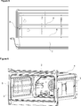
- Figure 1 – is the perspective view of an oven.
- Figure 2 – is the perspective view of a support unit.
- Figure 3 — is the partial perspective view of the casing, the carrier and the insulation means related to an embodiment of the present invention.
- Figure 4 – is the partial cross-sectional view of the carrier and the insulation means related to an embodiment of the present invention.
- Figure 5 — is the partial sideways view of the casing, the carrier and the insulation means related to an embodiment of the present invention.
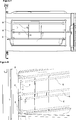
- Figure 6 — is the perspective view of the casing, the support unit and the insulation means related to another embodiment of the present invention.
- Figure 7 — is the sideways view of the casing, the support unit and the insulation means related to another embodiment of the present invention.
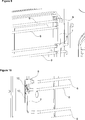
- Figure 8 — is the partial perspective view of the casing, the carrier and the insulation means related to another embodiment of the present invention.
- Figure 9 – is the partial perspective view of the casing, the carrier and the insulation means from another angle related to another embodiment of the present invention.
- Figure 10 – is the partial perspective view of the casing, the carrier and the insulation means related to another embodiment of the present invention.
- the oven (1) comprises a cooking cavity (2) wherein the trays (T) containing the foodstuffs to be cooked are placed, a casing (4) surrounding the cooking cavity (2), configured like a box with the front side open, having two opposite side walls (3) and a support unit (5) mounted to the inner surface of the side wall (3) facing the cooking cavity (2) and supporting the tray (T) placed thereon.
- the oven (1) of the present invention further more comprises a capacitance measuring means (10) the two ends of which are connected to the casing (4) and used for measuring the capacitance difference between these ends, an insulation means (8) for insulating the portions of the casing (4) whereto the ends of the capacitance measuring means (10) are connected and a control unit (9) that determines presence of the tray (T) by detecting the change in the capacitance difference measured by the capacitance measuring means (10) when the tray (T) is placed into the cooking cavity (2).
- a capacitance measuring means (10) the two ends of which are connected to the casing (4) and used for measuring the capacitance difference between these ends
- an insulation means (8) for insulating the portions of the casing (4) whereto the ends of the capacitance measuring means (10) are connected
- a control unit (9) that determines presence of the tray (T) by detecting the change in the capacitance difference measured by the capacitance measuring means (10) when the tray (T) is placed into the cooking cavity (2).
- Both ends of the capacitance measuring means (10) are connected to the casing (4) and an electric circuit is formed where the capacitance difference between the two ends are measured.
- the capacitance difference between the two ends is measured by means of the electric current applied to the ends of the capacitance measuring means (10).
- One part of the casing (4) is provided to be insulated from the other part by means of the insulation means (8) that remains between the ends of the capacitance measuring means (10).
- the insulated part of the casing (4) is provided to function as capacitor by means of the insulation means (8) and the capacitance measuring means (10).
- the control unit (9) saves the capacitance difference measured between the ends of the capacitance measuring means (10) as the reference value in its memory when the tray (T) is not present in the cooking cavity (2). In order to determine whether or not the tray (T) is present in the cooking cavity (2), the control unit (9) measures the capacitance difference between the ends of the capacitance measuring means (10) and compares it with the reference value, if there is a change between the reference value and the measured capacitance difference, then decides that the tray (T) is present in the cooking cavity (2).
- the user is informed by the control unit (9) about the presence of the tray (T) in the cooking cavity (2) and the tray (T) is prevented from remaining in the cooking cavity (2).
- the tray (T) is prevented from being damaged by the high temperature.
- an extra sensor for detecting the presence of the tray (T) is not necessary, whether or not a tray (T) is present in the cooking cavity (2) is easily determined by the capacitance measuring means (10).
- the support unit (5) comprises more than one carrier (6), extending from the front backwards, parallel to the side wall (3) in the horizontal direction, whereon the tray (T) is placed and at least one connector (7) that extends in the vertical direction to the carriers (6).
- the carriers (6) extend on the side wall (3), preferably in groups of two and provide the trays (T) placed one over the other and spaced apart into the cooking cavity (2) to be supported from their sides.
- the insulation means (8) provides the entire support unit (5) to be insulated from the casing (4).
- the support unit (5) is produced as a single piece preferably by way of attaching to each other the carriers (6) arranged one over the other by means of two separate connectors (7) situated at the front and back.
- the support unit (5) is mounted on the side wall (3) by bending the two ends of a carrier (6) preferably located in the middle so as to be vertical to the carrier (6) and by inserting the bent ends into the assembly holes situated on the side wall (3).
- the insulation means (8) is placed into the assembly hole such that the portion of the carrier (6) extending inside the assembly hole is surrounded all around. Thus, the contact of the carrier (6) is cut off from the casing (4).
- the support unit (5) Since the support unit (5) is fixed to the casing (4) by means of the carrier (6), the contact of the casing (4) with the support unit (5) is cut off by means of the insulation means (8).
- one end of the capacitance measuring means (10) is connected to the casing (4) and the other end to the support unit (5) that is insulated from the casing (4) by the insulation means (8).
- the end of the capacitance measuring means (10) connected to the support unit (5) is connected to the portion of the carrier (6) remaining at the rear side of the casing (4) that is cut off from contact with the casing (4).
- the control unit (9) detects the presence of the tray (T) in the cooking cavity (2) from the detected change in the capacitance difference.
- the surface areas of the carriers (6) are different from one another. Since the capacitance difference between the support unit (5) and the casing (4) measured by the capacitance measuring means (10) depends on the surface area of the carriers (6), the capacitance difference measured by the control unit (9) shows variability with respect to the position of the carrier (6) in the cooking cavity (2) whereon the tray (T) is placed. Thus, the position of the tray (T) in the cooking cavity (2), in other words on which carrier (6) it is placed, is determined by the control unit (9). Consequently, the tray (T) is provided to be placed on the carrier (6) at the level that is suitable for the selected cooking function. Accordingly, the cooking quality is improved and the cooking duration is kept at the optimum level.
- the insulation means (8) is ring-shaped.
- the insulation means (8) is provided to surround the almost cylindrical-shaped carrier (6) all around.
- the insulation means (8) provides one carrier (6), from the carriers (6) which are positioned to be one above the other and having the tray (T) therebetween, to be insulated from the other carrier (6).
- One end of the capacitance measuring means (10) is connected to the insulated carrier (6), the other end to the uninsulated carrier (6).
- an electric circuit is formed between the insulated carrier (6) and the uninsulated carrier (6).
- the insulated carrier (6) and the uninsulated carrier (6) are provided to function as a capacitor by means of the insulation means (8) and the capacitance measuring means (10).
- a different capacitance measuring means (10) is connected to the end of each pair of carriers (6) that are situated at different levels in the cooking cavity (2).
- the control unit (9) determines the position of the tray (T) inside the cooking cavity (2) depending on the change in capacitance difference measured by each capacitance measuring means (10). Consequently, the cooking quality is improved by providing the tray (T) to be placed on the carrier (6) that is at the suitable level for the selected cooking function.
- the connector (7) is pipe-shaped.
- the capacitance measuring means (10) that provides the electrical connection between the insulated carrier (6) and the uninsulated carrier (6), with the tray (T) placed therebetween, is partially disposed into the connector (7).
- measurement of capacitance between the carriers (6) is performed without distorting the esthetic appearance of the cooking cavity (2).
- the insulation means (8) is produced from ceramic. Since ceramic is a material that can withstand high temperatures, it is not adversely affected by the high temperature during cleaning of the cooking cavity (2).
- the possibility of the tray (T) remaining in the cooking cavity (2) during cleaning is prevented by determining whether or not the tray (T) is present in the cooking cavity (2). Furthermore, in the oven (1) of the present invention, the cooking quality is improved by determining the position of the tray (T), containing the foodstuffs that are cooked, in the cooking cavity (2).
Landscapes
- Engineering & Computer Science (AREA)
- Chemical & Material Sciences (AREA)
- Combustion & Propulsion (AREA)
- Mechanical Engineering (AREA)
- General Engineering & Computer Science (AREA)
- Electric Stoves And Ranges (AREA)
- Electric Ovens (AREA)
Abstract
The present invention relates to an oven (1) comprising a cooking cavity (2) wherein the trays (T) are placed, a casing (4) surrounding the cooking cavity (2), configured as an open front box shape with two opposite side walls (3) and having a support unit (5) mounted on the inner surface of the side wall (3) facing the cooking cavity (2), supporting the tray (T) placed thereon, and wherein the presence and position of the tray (T) in the cooking cavity (2) are detected.
Description
The present invention relates to an oven wherein the presence of the tray in the cooking cavity is detected and wherein the position of the tray in which the cooking process is performed is determined.
In self cleaning ovens primarily the pyrolytic ovens, the accumulated oils in the cooking cavity are burned to ashes by increasing the temperature of the cooking cavity to very high values. The user provides the cleaning of the cooking cavity by wiping the ashes. During this cleaning process wherein the oven is operated at very high temperature value, the cooking utensils like trays, grills are not desired to remain in the cooking cavity. Otherwise, the cooking utensils are adversely affected by the high temperature in the cooking cavity, problems arise like burning of the cooking utensils and the foodstuffs etc that may possibly be located thereon.
Furthermore, in ovens, support units having carriers are used which are mounted to the side walls for arranging the trays one above the other and spaced apart inside the cooking cavity. The cooking quality and duration depends on the position of the carrier, whereon the tray is placed, in the cooking cavity since the distance of each carrier to the heaters and the fan changes. Preferably in ovens having automatic cooking features, the level of the carrier whereto the tray has to be placed, in other words, on which carrier the tray has to be placed, is predetermined by the producer. The user places the tray on the carrier described by the producer in the operation manual according to the selected cooking function. In the case the user does not place the tray on the carrier corresponding to the respective cooking function described by the producer, the cooking duration is prolonged and the cooking quality deteriorates. Therefore, determining the position of the carrier whereon the tray is placed and informing the user whether or not the placement is done correctly are important in terms of cooking quality and duration.
In the state of the art Japanese Patent Application No. JP2006288778, a cooker is described comprising a tray discrimination means for discriminating the presence/absence of the tray based on the temperature detected by the temperature detection means used for measuring temperature of the heating chamber during cleaning of the heating chamber.
In the state of the art Japanese Patent Document No. JP63153329, a heating device is described wherein the distance to the foodstuff to be cooked is detected by means of a distance measuring sensor.
In the state of the art United States Patent Document No. US7183521, an oven is described comprising a rack sensor detecting whether or not the tray is present inside the cooking cavity and a control unit that starts cooking cavity cleaning process depending on data delivered by the rack sensor.
The aim of the present invention is the realization of an oven wherein presence and position of the tray in the cooking cavity are detected.
The oven realized in order to attain the aim of the present invention, explicated in the first claim and the respective claims thereof, comprises a casing having a support unit, mounted to the side wall, used for placing the trays one above the other and spaced apart in the cooking cavity. The oven of the present invention furthermore comprises a capacitance measuring means, both ends of which are connected to the casing, used for measuring the capacitance difference between the two ends, an insulation means for separating the portions of the casing whereto the ends of the capacitance measuring means are connected and a control unit that determines the absence/presence of the tray depending on the capacitance difference measured by the capacitance measuring means when the tray is placed into the cooking cavity. Electric current is applied to the portions of the casing that are insulated from each other by means of the capacitance measuring means and the capacitance difference between these portions is measured. The control unit detects the change in the capacitance difference measured by the capacitance measuring means when the tray is placed into the cooking cavity and determines the presence of the tray in the cooking cavity accordingly. By means of the insulation means and the capacitance measuring means, the existence of the tray inside the cooking cavity is determined in a simple manner by measuring the capacitance. Consequently, the user is informed about the presence/absence of the tray in the cooking cavity during the cleaning process of the cooking cavity which is performed at high temperature.
The support unit comprises more than one carrier, mounted to both side walls of the casing, extending in the horizontal direction from the front backwards and connectors that extend perpendicular to the carriers and used for connecting the carriers.
In an embodiment of the present invention, the insulation means provides the entire support unit to be insulated from the casing. The support unit is fixed onto the side wall from two separate points, by means of assembly holes, one preferably located at the front side and the other at the rear side of the side wall. The contact of the support unit and the casing is cut off by means of the insulation means borne inside the assembly holes whereby the support unit is fixed to the side wall. One end of the capacitance measuring means is connected to the casing and the other end to the support unit that is insulated from the casing. The casing and the support unit are provided to function as a capacitor by applying electric current between the ends of the capacitance measuring means. When the tray is placed into the cooking cavity, the capacitance difference between the casing and the support unit measured by means of the capacitance measuring means changes. The control unit decides the presence of the tray by comparing the capacitance difference measured when the cooking cavity is empty with the capacitance difference measured when the tray is placed into the cooking cavity.
In another embodiment of the present invention, the surface areas of the carriers at different levels in the cooking cavity are different from one another. Since the capacitance difference measured by the capacitance measuring means depends on the surface areas of the carriers, the capacitance difference measured when the tray is placed on the carriers at different levels is different from each other. Accordingly, the capacitance difference change detected by the control unit is different from one another depending on the position of the tray placed inside the cooking cavity. Consequently, the position of the tray inside the cooking cavity is determined by the control unit.
In another embodiment of the present invention, the insulation means is shaped like a ring through which the carrier can be inserted. The carrier is prevented from contacting the casing by inserting the insulation means around the carrier connected to the side wall.
In another embodiment of the present invention, the insulation means provides the two carriers, that are positioned one above the other and between which the tray is placed, to be insulated from one another. In this embodiment, the ends of the capacitance measuring means are connected to the carriers that are insulated from one another. The capacitance difference between the carriers that are insulated from one another is measured by the capacitance measuring means. When the tray is disposed between the said two carriers, the capacitance difference between the carriers changes. The control unit determines whether or not the tray is placed between the carriers according to the capacitance difference change and informs the user . In this embodiment, a different capacitance measuring means is connected to every carrier pair, at different levels from each other and between which the tray is placed. Thus, the carrier whereon the tray is placed can be determined since the capacitance difference between each two carriers can be measured separately. The cooking process is performed on the carrier at the level that is suitable for the selected cooking function by determining the position of the tray in the cooking cavity and the cooking quality is improved.
In a version of this embodiment, the connector is configured as a pipe through which the capacitance measuring means providing the electrical connection between the carriers is inserted.
In another embodiment of the present invention, the insulation means is produced from ceramic. Thus, the resistance of the insulation means against the high temperature occurring during cleaning of the cooking cavity is increased.
In the oven of the present invention, the presence of the tray in the cooking cavity is prevented by determining whether or not the tray is present in the cooking cavity during cleaning of the cooking cavity. Consequently, the tray is prevented from being affected adversely by the high temperature in the cooking cavity.
The oven realized in order to attain the aim of the present invention is illustrated in the attached figures, where:
Figure 1 – is the perspective view of an oven.
Figure 2 – is the perspective view of a support unit.
Figure 3 – is the partial perspective view of the casing, the carrier and the insulation means related to an embodiment of the present invention.
Figure 4 – is the partial cross-sectional view of the carrier and the insulation means related to an embodiment of the present invention.
Figure 5 – is the partial sideways view of the casing, the carrier and the insulation means related to an embodiment of the present invention.
Figure 6 – is the perspective view of the casing, the support unit and the insulation means related to another embodiment of the present invention.
Figure 7 – is the sideways view of the casing, the support unit and the insulation means related to another embodiment of the present invention.
Figure 8 – is the partial perspective view of the casing, the carrier and the insulation means related to another embodiment of the present invention.
Figure 9 – is the partial perspective view of the casing, the carrier and the insulation means from another angle related to another embodiment of the present invention.
Figure 10 – is the partial perspective view of the casing, the carrier and the insulation means related to another embodiment of the present invention.
The elements illustrated in the figures are numbered as follows:
- Oven
- Cooking cavity
- Side wall
- Casing
- Support unit
- Carrier
- Connector
- Insulation means
- Control unit
- Capacitance measuring means
The oven (1) comprises a cooking cavity (2) wherein the trays (T) containing the foodstuffs to be cooked are placed, a casing (4) surrounding the cooking cavity (2), configured like a box with the front side open, having two opposite side walls (3) and a support unit (5) mounted to the inner surface of the side wall (3) facing the cooking cavity (2) and supporting the tray (T) placed thereon.
The oven (1) of the present invention further more comprises a capacitance measuring means (10) the two ends of which are connected to the casing (4) and used for measuring the capacitance difference between these ends, an insulation means (8) for insulating the portions of the casing (4) whereto the ends of the capacitance measuring means (10) are connected and a control unit (9) that determines presence of the tray (T) by detecting the change in the capacitance difference measured by the capacitance measuring means (10) when the tray (T) is placed into the cooking cavity (2).
Both ends of the capacitance measuring means (10) are connected to the casing (4) and an electric circuit is formed where the capacitance difference between the two ends are measured. When it is desired to determine presence of the tray (T) in the cooking cavity (2), the capacitance difference between the two ends is measured by means of the electric current applied to the ends of the capacitance measuring means (10). One part of the casing (4) is provided to be insulated from the other part by means of the insulation means (8) that remains between the ends of the capacitance measuring means (10). The insulated part of the casing (4) is provided to function as capacitor by means of the insulation means (8) and the capacitance measuring means (10).
The control unit (9) saves the capacitance difference measured between the ends of the capacitance measuring means (10) as the reference value in its memory when the tray (T) is not present in the cooking cavity (2). In order to determine whether or not the tray (T) is present in the cooking cavity (2), the control unit (9) measures the capacitance difference between the ends of the capacitance measuring means (10) and compares it with the reference value, if there is a change between the reference value and the measured capacitance difference, then decides that the tray (T) is present in the cooking cavity (2).
Thus, prior to the cleaning process performed by increasing the temperature of the cooking cavity (2) to very high temperature values, the user is informed by the control unit (9) about the presence of the tray (T) in the cooking cavity (2) and the tray (T) is prevented from remaining in the cooking cavity (2). Thus, the tray (T) is prevented from being damaged by the high temperature. Furthermore, an extra sensor for detecting the presence of the tray (T) is not necessary, whether or not a tray (T) is present in the cooking cavity (2) is easily determined by the capacitance measuring means (10).
The support unit (5) comprises more than one carrier (6), extending from the front backwards, parallel to the side wall (3) in the horizontal direction, whereon the tray (T) is placed and at least one connector (7) that extends in the vertical direction to the carriers (6).
The carriers (6) extend on the side wall (3), preferably in groups of two and provide the trays (T) placed one over the other and spaced apart into the cooking cavity (2) to be supported from their sides.
In an embodiment of the present invention, the insulation means (8) provides the entire support unit (5) to be insulated from the casing (4). The support unit (5) is produced as a single piece preferably by way of attaching to each other the carriers (6) arranged one over the other by means of two separate connectors (7) situated at the front and back. The support unit (5) is mounted on the side wall (3) by bending the two ends of a carrier (6) preferably located in the middle so as to be vertical to the carrier (6) and by inserting the bent ends into the assembly holes situated on the side wall (3). The insulation means (8) is placed into the assembly hole such that the portion of the carrier (6) extending inside the assembly hole is surrounded all around. Thus, the contact of the carrier (6) is cut off from the casing (4). Since the support unit (5) is fixed to the casing (4) by means of the carrier (6), the contact of the casing (4) with the support unit (5) is cut off by means of the insulation means (8). In this embodiment, one end of the capacitance measuring means (10) is connected to the casing (4) and the other end to the support unit (5) that is insulated from the casing (4) by the insulation means (8). The end of the capacitance measuring means (10) connected to the support unit (5) is connected to the portion of the carrier (6) remaining at the rear side of the casing (4) that is cut off from contact with the casing (4).
When the tray (T) is placed into the cooking cavity (2), the capacitance difference between the casing (4) and the support unit (5) changes. The control unit (9) detects the presence of the tray (T) in the cooking cavity (2) from the detected change in the capacitance difference.
In another embodiment of the present invention, the surface areas of the carriers (6) are different from one another. Since the capacitance difference between the support unit (5) and the casing (4) measured by the capacitance measuring means (10) depends on the surface area of the carriers (6), the capacitance difference measured by the control unit (9) shows variability with respect to the position of the carrier (6) in the cooking cavity (2) whereon the tray (T) is placed. Thus, the position of the tray (T) in the cooking cavity (2), in other words on which carrier (6) it is placed, is determined by the control unit (9). Consequently, the tray (T) is provided to be placed on the carrier (6) at the level that is suitable for the selected cooking function. Accordingly, the cooking quality is improved and the cooking duration is kept at the optimum level.
In another embodiment of the present invention, the insulation means (8) is ring-shaped. Thus, the insulation means (8) is provided to surround the almost cylindrical-shaped carrier (6) all around.
In another embodiment of the present invention, the insulation means (8) provides one carrier (6), from the carriers (6) which are positioned to be one above the other and having the tray (T) therebetween, to be insulated from the other carrier (6). One end of the capacitance measuring means (10) is connected to the insulated carrier (6), the other end to the uninsulated carrier (6). Thus, an electric circuit is formed between the insulated carrier (6) and the uninsulated carrier (6). The insulated carrier (6) and the uninsulated carrier (6) are provided to function as a capacitor by means of the insulation means (8) and the capacitance measuring means (10). A different capacitance measuring means (10) is connected to the end of each pair of carriers (6) that are situated at different levels in the cooking cavity (2). Thus, the capacitance difference between each carrier (6) pair with the tray (T) placed therebetween is provided to be measured separately from one another. Accordingly, the control unit (9) determines the position of the tray (T) inside the cooking cavity (2) depending on the change in capacitance difference measured by each capacitance measuring means (10). Consequently, the cooking quality is improved by providing the tray (T) to be placed on the carrier (6) that is at the suitable level for the selected cooking function.
In a version of this embodiment, the connector (7) is pipe-shaped. The capacitance measuring means (10) that provides the electrical connection between the insulated carrier (6) and the uninsulated carrier (6), with the tray (T) placed therebetween, is partially disposed into the connector (7). Thus, measurement of capacitance between the carriers (6) is performed without distorting the esthetic appearance of the cooking cavity (2).
In another embodiment of the present invention, the insulation means (8) is produced from ceramic. Since ceramic is a material that can withstand high temperatures, it is not adversely affected by the high temperature during cleaning of the cooking cavity (2).
In the oven (1) of the present invention, the possibility of the tray (T) remaining in the cooking cavity (2) during cleaning is prevented by determining whether or not the tray (T) is present in the cooking cavity (2). Furthermore, in the oven (1) of the present invention, the cooking quality is improved by determining the position of the tray (T), containing the foodstuffs that are cooked, in the cooking cavity (2).
It is to be understood that the present invention is not limited by the embodiments disclosed above and a person skilled in the art can easily introduce different embodiments. These should be considered within the scope of the protection postulated by the claims of the present invention.
Claims (8)
- An oven (1) comprising a cooking cavity (2) wherein the trays (T) are placed, a casing (4) surrounding the cooking cavity (2), configured like a box with the front side open, having two opposite side walls (3) and a support unit (5) mounted to the inner surface of the side wall (3) facing the cooking cavity (2) and supporting the tray (T) placed thereon,characterized by a capacitance measuring means (10) used for measuring the capacitance difference between its two ends by connecting these two ends to the casing (4), an insulation means (8) for insulating the portions of the casing (4) whereto the ends of the capacitance measuring means (10) are connected and a control unit (9) that determines presence of the tray (T) by detecting the capacitance difference measured by the capacitance measuring means (10) when the tray (T) is placed into the cooking cavity (2).
- An oven (1) as in Claim 1, characterized by the support unit (5) comprising more than one carrier (6), whereon the tray (T) is placed, extending from the front backwards, parallel to the side wall (3) in the horizontal direction, and at least one connector (7) that extends in the vertical direction to the carriers (6).
- An oven (1) as in Claim 1 or 2, characterized by an insulation means (8) that provides the entire support unit (5) to be insulated from the casing (4).
- An oven (1) as in any one of the above claims, characterized by the carriers (6) the surface areas of which are different from one another.
- An oven (1) as in any one of the above Claims, characterized by the ring-shaped insulation means (8).
- An oven (1) as in Claim 1 or 2, characterized by the insulation means (8) providing to insulate one carrier (6), from the carriers (6) which are positioned to be one above the other with the tray (T) placed therebetween, to be insulated from the other carrier (6).
- An oven (1) as in Claim 6, characterized by the pipe-shaped connector (7).
- An oven (1) as in any one of the above Claims, characterized by the insulation means (8) that is produced from ceramic.
Priority Applications (1)
| Application Number | Priority Date | Filing Date | Title |
|---|---|---|---|
| EP12720140.8A EP2705306A1 (en) | 2011-05-06 | 2012-05-04 | An oven wherein presence of tray is detected in the cooking cavity |
Applications Claiming Priority (2)
| Application Number | Priority Date | Filing Date | Title |
|---|---|---|---|
| TR2011/04463A TR201104463A1 (en) | 2011-05-06 | 2011-05-06 | The presence of a tray inside the baking room is an oven detected. |
| TRA2011/04463 | 2011-05-06 |
Publications (1)
| Publication Number | Publication Date |
|---|---|
| WO2012152692A1 true WO2012152692A1 (en) | 2012-11-15 |
Family
ID=46052733
Family Applications (1)
| Application Number | Title | Priority Date | Filing Date |
|---|---|---|---|
| PCT/EP2012/058251 Ceased WO2012152692A1 (en) | 2011-05-06 | 2012-05-04 | An oven wherein presence of tray is detected in the cooking cavity |
Country Status (3)
| Country | Link |
|---|---|
| EP (1) | EP2705306A1 (en) |
| TR (1) | TR201104463A1 (en) |
| WO (1) | WO2012152692A1 (en) |
Cited By (3)
| Publication number | Priority date | Publication date | Assignee | Title |
|---|---|---|---|---|
| WO2018202376A1 (en) * | 2017-05-04 | 2018-11-08 | Arcelik Anonim Sirketi | A microwave oven comprising an oven tray |
| DE102017111608A1 (en) | 2017-05-29 | 2018-11-29 | Miele & Cie. Kg | kitchen appliance |
| EP4443058A1 (en) * | 2023-04-03 | 2024-10-09 | Rational Aktiengesellschaft | Cooking device with rack for cooking goods |
Citations (10)
| Publication number | Priority date | Publication date | Assignee | Title |
|---|---|---|---|---|
| DE8704211U1 (en) * | 1987-03-20 | 1987-10-29 | Licentia Patent-Verwaltungs-Gmbh, 6000 Frankfurt | Baking and roasting oven |
| DE8713772U1 (en) * | 1987-10-14 | 1988-05-26 | Licentia Patent-Verwaltungs-Gmbh, 6000 Frankfurt | Baking and roasting oven for microwave and/or resistance heating operation |
| JPS63153329A (en) | 1986-12-17 | 1988-06-25 | Matsushita Electric Ind Co Ltd | Heating device |
| JP2006288778A (en) | 2005-04-12 | 2006-10-26 | Matsushita Electric Ind Co Ltd | Cooker |
| US7183521B2 (en) | 2004-03-31 | 2007-02-27 | Electrolux Home Products, Inc. | Rack Sensor |
| DE102008022227B3 (en) * | 2008-05-06 | 2009-06-25 | Rational Ag | Cooking device has oven with multiple electrically conductive withdrawable holders that defines withdrawable level, where electrically conductive slot is inserted in each withdrawable level |
| DE102008020189A1 (en) * | 2008-04-22 | 2009-11-05 | Rational Ag | Cooking equipment, has set of electric circuits associated with insertion plane locked by pushing insert into one of set of insertion planes, where electrically conductive region of insert and light sources are part electric circuit |
| DE102009002864A1 (en) * | 2009-05-06 | 2010-11-18 | BSH Bosch und Siemens Hausgeräte GmbH | Household appliance device has household appliance which has detection unit for detecting household component, where household component has identification units |
| DE102009029147A1 (en) * | 2009-09-02 | 2011-03-03 | BSH Bosch und Siemens Hausgeräte GmbH | Household appliance e.g. baking oven, for preparing e.g. cake, has processor stimulating sensor unit with predetermined carrier frequency, where information of sensor unit in frequency region is evaluated by processor |
| DE102010029197A1 (en) * | 2010-05-20 | 2011-11-24 | BSH Bosch und Siemens Hausgeräte GmbH | Cooking device, particularly oven, comprises cooking chamber wall and cooking chamber which is limited with drawer levels, where detection unit is provided for detecting occupancy of drawer levels by component part |
Family Cites Families (1)
| Publication number | Priority date | Publication date | Assignee | Title |
|---|---|---|---|---|
| DE19954470B4 (en) * | 1999-11-12 | 2006-02-09 | AEG Hausgeräte GmbH | Apparatus and method for operating a cooking oven with pyrolysis function |
-
2011
- 2011-05-06 TR TR2011/04463A patent/TR201104463A1/en unknown
-
2012
- 2012-05-04 WO PCT/EP2012/058251 patent/WO2012152692A1/en not_active Ceased
- 2012-05-04 EP EP12720140.8A patent/EP2705306A1/en not_active Withdrawn
Patent Citations (10)
| Publication number | Priority date | Publication date | Assignee | Title |
|---|---|---|---|---|
| JPS63153329A (en) | 1986-12-17 | 1988-06-25 | Matsushita Electric Ind Co Ltd | Heating device |
| DE8704211U1 (en) * | 1987-03-20 | 1987-10-29 | Licentia Patent-Verwaltungs-Gmbh, 6000 Frankfurt | Baking and roasting oven |
| DE8713772U1 (en) * | 1987-10-14 | 1988-05-26 | Licentia Patent-Verwaltungs-Gmbh, 6000 Frankfurt | Baking and roasting oven for microwave and/or resistance heating operation |
| US7183521B2 (en) | 2004-03-31 | 2007-02-27 | Electrolux Home Products, Inc. | Rack Sensor |
| JP2006288778A (en) | 2005-04-12 | 2006-10-26 | Matsushita Electric Ind Co Ltd | Cooker |
| DE102008020189A1 (en) * | 2008-04-22 | 2009-11-05 | Rational Ag | Cooking equipment, has set of electric circuits associated with insertion plane locked by pushing insert into one of set of insertion planes, where electrically conductive region of insert and light sources are part electric circuit |
| DE102008022227B3 (en) * | 2008-05-06 | 2009-06-25 | Rational Ag | Cooking device has oven with multiple electrically conductive withdrawable holders that defines withdrawable level, where electrically conductive slot is inserted in each withdrawable level |
| DE102009002864A1 (en) * | 2009-05-06 | 2010-11-18 | BSH Bosch und Siemens Hausgeräte GmbH | Household appliance device has household appliance which has detection unit for detecting household component, where household component has identification units |
| DE102009029147A1 (en) * | 2009-09-02 | 2011-03-03 | BSH Bosch und Siemens Hausgeräte GmbH | Household appliance e.g. baking oven, for preparing e.g. cake, has processor stimulating sensor unit with predetermined carrier frequency, where information of sensor unit in frequency region is evaluated by processor |
| DE102010029197A1 (en) * | 2010-05-20 | 2011-11-24 | BSH Bosch und Siemens Hausgeräte GmbH | Cooking device, particularly oven, comprises cooking chamber wall and cooking chamber which is limited with drawer levels, where detection unit is provided for detecting occupancy of drawer levels by component part |
Non-Patent Citations (1)
| Title |
|---|
| See also references of EP2705306A1 * |
Cited By (4)
| Publication number | Priority date | Publication date | Assignee | Title |
|---|---|---|---|---|
| WO2018202376A1 (en) * | 2017-05-04 | 2018-11-08 | Arcelik Anonim Sirketi | A microwave oven comprising an oven tray |
| DE102017111608A1 (en) | 2017-05-29 | 2018-11-29 | Miele & Cie. Kg | kitchen appliance |
| EP3410018A1 (en) * | 2017-05-29 | 2018-12-05 | Miele & Cie. KG | Kitchen appliance |
| EP4443058A1 (en) * | 2023-04-03 | 2024-10-09 | Rational Aktiengesellschaft | Cooking device with rack for cooking goods |
Also Published As
| Publication number | Publication date |
|---|---|
| TR201104463A1 (en) | 2012-11-21 |
| EP2705306A1 (en) | 2014-03-12 |
Similar Documents
| Publication | Publication Date | Title |
|---|---|---|
| EP3324163B1 (en) | Temperature probe for domestic oven and domestic oven using such probe | |
| US20160033140A1 (en) | Oven appliance with interior cleanliness sensor | |
| US11747023B2 (en) | Adaptable port for an oven appliance | |
| CN107411540A (en) | Cooker, induction cooker, cooker assembly and information indication method | |
| EP3453977B1 (en) | Cooking apparatus with humidity sensor and method for calculating a humidity level in such an oven | |
| US9078449B2 (en) | Cook top grate as utensil size/presence detector | |
| CN108309034A (en) | Electric cooking pot and its culinary art control device and cooking control method | |
| WO2012152692A1 (en) | An oven wherein presence of tray is detected in the cooking cavity | |
| JP2011023159A (en) | Heating cooker | |
| JP4934168B2 (en) | Temperature sensor | |
| US20220187022A1 (en) | Cooking appliance having an imaging device for identifying a type of temperature sensing device | |
| US12449317B2 (en) | Adaptable cooking appliance circuitry for controlling cooking accessories | |
| CN108309038A (en) | Electric cooking pot and its anti-spilled control device and anti-overflow discharge control method | |
| CN102192546B (en) | Method for identifying temperature of food through toast rack array sensor | |
| CN113390106B (en) | Control method, cooking appliance and storage medium | |
| EP2886024B1 (en) | Improved detection assembly for electric appliances | |
| JP4259492B2 (en) | Cooker | |
| CN217959753U (en) | Frying and roasting appliance | |
| CN221450461U (en) | Temperature measuring device and cooking equipment using same | |
| CN207379625U (en) | Pan, electromagnetism stove and stove assembly | |
| CN215175296U (en) | Cooking utensil | |
| US20240264010A1 (en) | Cooking accessory plug including one or more unique resistive values | |
| KR20110011818A (en) | Oven range with weight sensing unit and control method | |
| US7644651B2 (en) | Method and control arrangement for terminating accidental switch on of a deep fryer apparatus not filled with oil | |
| JP5785974B2 (en) | Cooker |
Legal Events
| Date | Code | Title | Description |
|---|---|---|---|
| 121 | Ep: the epo has been informed by wipo that ep was designated in this application |
Ref document number: 12720140 Country of ref document: EP Kind code of ref document: A1 |
|
| WWE | Wipo information: entry into national phase |
Ref document number: 2012720140 Country of ref document: EP |
|
| NENP | Non-entry into the national phase |
Ref country code: DE |