WO2012153560A1 - 乗員拘束装置及び乗員拘束方法 - Google Patents
乗員拘束装置及び乗員拘束方法 Download PDFInfo
- Publication number
- WO2012153560A1 WO2012153560A1 PCT/JP2012/054601 JP2012054601W WO2012153560A1 WO 2012153560 A1 WO2012153560 A1 WO 2012153560A1 JP 2012054601 W JP2012054601 W JP 2012054601W WO 2012153560 A1 WO2012153560 A1 WO 2012153560A1
- Authority
- WO
- WIPO (PCT)
- Prior art keywords
- vehicle
- occupant
- pretensioner
- rollover
- airbag
- Prior art date
- Legal status (The legal status is an assumption and is not a legal conclusion. Google has not performed a legal analysis and makes no representation as to the accuracy of the status listed.)
- Ceased
Links
Images


Classifications
-
- B—PERFORMING OPERATIONS; TRANSPORTING
- B60—VEHICLES IN GENERAL
- B60R—VEHICLES, VEHICLE FITTINGS, OR VEHICLE PARTS, NOT OTHERWISE PROVIDED FOR
- B60R21/00—Arrangements or fittings on vehicles for protecting or preventing injuries to occupants or pedestrians in case of accidents or other traffic risks
- B60R21/02—Occupant safety arrangements or fittings, e.g. crash pads
- B60R21/16—Inflatable occupant restraints or confinements designed to inflate upon impact or impending impact, e.g. air bags
- B60R21/18—Inflatable occupant restraints or confinements designed to inflate upon impact or impending impact, e.g. air bags the inflatable member formed as a belt or harness or combined with a belt or harness arrangement
-
- B—PERFORMING OPERATIONS; TRANSPORTING
- B60—VEHICLES IN GENERAL
- B60R—VEHICLES, VEHICLE FITTINGS, OR VEHICLE PARTS, NOT OTHERWISE PROVIDED FOR
- B60R21/00—Arrangements or fittings on vehicles for protecting or preventing injuries to occupants or pedestrians in case of accidents or other traffic risks
- B60R21/01—Electrical circuits for triggering passive safety arrangements, e.g. airbags, safety belt tighteners, in case of vehicle accidents or impending vehicle accidents
- B60R21/013—Electrical circuits for triggering passive safety arrangements, e.g. airbags, safety belt tighteners, in case of vehicle accidents or impending vehicle accidents including means for detecting collisions, impending collisions or roll-over
- B60R21/0132—Electrical circuits for triggering passive safety arrangements, e.g. airbags, safety belt tighteners, in case of vehicle accidents or impending vehicle accidents including means for detecting collisions, impending collisions or roll-over responsive to vehicle motion parameters, e.g. to vehicle longitudinal or transversal deceleration or speed value
-
- B—PERFORMING OPERATIONS; TRANSPORTING
- B60—VEHICLES IN GENERAL
- B60R—VEHICLES, VEHICLE FITTINGS, OR VEHICLE PARTS, NOT OTHERWISE PROVIDED FOR
- B60R21/00—Arrangements or fittings on vehicles for protecting or preventing injuries to occupants or pedestrians in case of accidents or other traffic risks
- B60R21/02—Occupant safety arrangements or fittings, e.g. crash pads
- B60R21/16—Inflatable occupant restraints or confinements designed to inflate upon impact or impending impact, e.g. air bags
- B60R21/23—Inflatable members
- B60R21/231—Inflatable members characterised by their shape, construction or spatial configuration
- B60R21/23138—Inflatable members characterised by their shape, construction or spatial configuration specially adapted for side protection
-
- B—PERFORMING OPERATIONS; TRANSPORTING
- B60—VEHICLES IN GENERAL
- B60R—VEHICLES, VEHICLE FITTINGS, OR VEHICLE PARTS, NOT OTHERWISE PROVIDED FOR
- B60R21/00—Arrangements or fittings on vehicles for protecting or preventing injuries to occupants or pedestrians in case of accidents or other traffic risks
- B60R21/02—Occupant safety arrangements or fittings, e.g. crash pads
- B60R21/16—Inflatable occupant restraints or confinements designed to inflate upon impact or impending impact, e.g. air bags
- B60R21/23—Inflatable members
- B60R21/231—Inflatable members characterised by their shape, construction or spatial configuration
- B60R21/232—Curtain-type airbags deploying mainly in a vertical direction from their top edge
-
- B—PERFORMING OPERATIONS; TRANSPORTING
- B60—VEHICLES IN GENERAL
- B60R—VEHICLES, VEHICLE FITTINGS, OR VEHICLE PARTS, NOT OTHERWISE PROVIDED FOR
- B60R21/00—Arrangements or fittings on vehicles for protecting or preventing injuries to occupants or pedestrians in case of accidents or other traffic risks
- B60R2021/0002—Type of accident
- B60R2021/0018—Roll-over
Definitions
- the present invention relates to an occupant restraint device and an occupant restraint method for restraining and protecting an occupant when there is a possibility that the vehicle rolls over.
- a side airbag that is deployed between the passenger's upper body and the door a curtain airbag that is deployed between the passenger's head and the door, and a seat belt with a built-in pretensioner are provided.
- the number of vehicles is increasing. Further, in a vehicle having such a function, when the vehicle rolls over toward the outside of the occupant, the curtain airbag is deployed to prevent the occupant's head from colliding with the door.
- the occupant when the vehicle starts to roll over, the occupant often approaches the outside (door side) of the vehicle. In this case, the gap between the occupant's head and the vehicle side wall (door, glass, pillar trim, etc.) is narrow, which causes a problem that the curtain airbag cannot be smoothly deployed.
- Patent Document 1 discloses an airbag control device that controls the deployment of a curtain airbag.
- the side airbag is deployed and at the same time, the seat belt pretensioner is activated.
- the occupant is moved to the inside of the vehicle (opposite to the door), and the occupant is fixed to the seat so that a gap is provided between the occupant's head and the vehicle side wall, thereby smoothly deploying the curtain airbag. .
- Patent Document 1 executes the deployment of the side airbag and the activation of the pretensioner at the same time. For this reason, the occupant is pressed against the inside of the vehicle by the side airbag while the occupant is strongly pressed against the seat back (the seat back portion) by the seat belt. Therefore, there has been a problem that the friction between the occupant and the seat back surface is increased, and when the side airbag is deployed, the occupant cannot be smoothly pressed against the inside of the vehicle.
- the present invention has been made to solve such conventional problems.
- the purpose of the occupant restraint device and occupant restraint method is to provide a gap between the occupant's head and the door and to smoothly deploy the curtain airbag when the vehicle rolls over. Is to provide.
- the occupant restraint device includes a curtain airbag, a side airbag, and a seat belt with a built-in pretensioner, and a rollover detection device that detects or estimates the rollover of the vehicle. Further, the occupant restraint device deploys the side airbag when the rollover of the vehicle is detected or estimated by the rollover detection device, and activates the pretensioner after a predetermined time has elapsed since the deployment of the side airbag, A control device that performs control to deploy the curtain airbag is provided.
- the occupant restraint method includes a step of preparing a curtain airbag, a side airbag, and a seat belt with a built-in pretensioner, and a step of detecting or estimating a vehicle rollover. Furthermore, the occupant restraint method includes a step of deploying the side airbag when a vehicle rollover is detected or estimated, and a step of operating the pretensioner after a predetermined time has elapsed when the side airbag is deployed. With. The occupant restraint method further includes a step of deploying the curtain airbag after the pretensioner is activated.
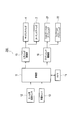
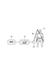
- FIG. 1 is a block diagram showing a configuration of an occupant restraint device according to the first embodiment of the present invention.
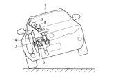
- FIG. 2 is an explanatory view showing an operation state of the occupant restraint device according to the first embodiment of the present invention, and shows a state when the vehicle starts to roll over.
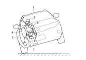
- FIG. 3 is an explanatory view showing an operating state of the occupant restraint device according to the first embodiment of the present invention, and shows a state when the side airbag is deployed.
- FIG. 4 is an explanatory view showing an operation state of the occupant restraint device according to the first embodiment of the present invention, and shows a state when the pretensioner is operated.
- FIG. 1 is a block diagram showing a configuration of an occupant restraint device according to the first embodiment of the present invention.
- FIG. 2 is an explanatory view showing an operation state of the occupant restraint device according to the first embodiment of the present invention, and shows a state when the vehicle starts to roll over.
- FIG. 3 is an ex
- FIG. 5 is an explanatory view showing an operation state of the occupant restraint device according to the first embodiment of the present invention, and shows a state when the curtain airbag is deployed.
- FIG. 6 is a flowchart showing the operation of the passenger restraint apparatus according to the first embodiment of the present invention.
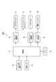
- FIG. 7 is a block diagram showing a configuration of an occupant restraint device according to the second embodiment of the present invention.
- FIG. 8 is an explanatory view showing an operating state of the occupant restraint device according to the second embodiment of the present invention, and shows a state when the vehicle starts to roll over.
- FIG. 9 is an explanatory view showing an operating state of the occupant restraint device according to the second embodiment of the present invention, and shows a state when the side airbag is deployed and the lap belt pretensioner is activated.
- FIG. 10 is an explanatory view showing an operating state of the occupant restraint device according to the second embodiment of the present invention, and shows a state when the shoulder belt pretensioner is operated.
- FIG. 11 is an explanatory view showing an operating state of the occupant restraint device according to the second embodiment of the present invention, and shows a state when the curtain airbag is deployed.
- FIG. 12 is a flowchart showing the operation of the passenger restraint apparatus according to the second embodiment of the present invention.
- FIG. 13 is a block diagram showing a configuration of an occupant restraint device according to the third embodiment of the present invention.
- FIG. 14 is an explanatory view showing an electric seat belt of an occupant restraint device according to a third embodiment of the present invention.
- FIG. 15 is a flowchart showing the operation of the passenger restraint apparatus according to the third embodiment of the present invention.
- FIG. 1 is a block diagram showing a configuration of an occupant restraint device according to the first embodiment of the present invention.
- an occupant restraint device 100 includes a roll angular velocity sensor 12 that detects acceleration of a roll angle generated in a vehicle, and a load sensor that detects whether or not an occupant is in the driver's seat or passenger seat of the vehicle. 13.
- the occupant restraint device 100 includes a control unit 11 that performs overall control and a timer 14 that measures time.
- the occupant restraint device 100 is provided on the side wall of the driver's seat and is deployed between the upper body of the occupant (driver) and the vehicle side wall during operation, and the head of the occupant during operation.
- a curtain airbag 2 is provided between the vehicle side wall and the vehicle.
- the occupant restraint device 100 includes an airbag driving unit 15 that controls driving of the airbags 2 and 4.
- the occupant restraint device 100 winds up the seat belt in a short time to seat the occupant (the seat back portion) and the seat cushion (the seat seat portion).
- a pretensioner 19 is provided to be fixed to.
- the occupant restraint device 100 also includes a pretensioner drive unit 16 that controls the drive of the pretensioner 19.
- the side airbag 4, the curtain airbag 2, and the pretensioner 19 are also provided on the passenger seat side. However, in the present embodiment, only the driver seat side is provided for the sake of simplicity. Is described.
- the control unit 11 performs a process of determining whether a driver or a passenger is on the passenger seat in the vehicle based on the detection signal of the load sensor 13. In addition, the control unit 11 calculates an angle in the roll direction of the vehicle by integrating the angular velocity signal output from the roll angular velocity sensor 12, and determines whether the vehicle rolls over based on the angle and the angular velocity. Processing to determine is performed. That is, the control unit 11 also has a function as a rollover detection device. And when it is judged by the control part 11 that a vehicle rolls over, the process which outputs the operation signal for operating the side airbag 4, the pretensioner 19, and the curtain airbag 2 by the procedure mentioned later is performed.
- step S11 of FIG. 6 the control unit 11 determines whether or not a vehicle rollover is detected. As described above, this process is performed based on the angular velocity output from the roll angular velocity sensor 12 and the angle obtained by integrating the angular velocity. Then, when the vehicle rotates in the roll direction (the direction of the arrow Y1 in FIG. 2) from the angular velocity and angle, and the vehicle cannot be overturned (when it is certain that the vehicle rolls over), the control unit 11 detects rollover. Note that the control unit 11 may estimate the rollover of the vehicle.
- the occupant 5 of the vehicle 1 moves to the outside of the vehicle by the inertial force caused by the lateral deceleration generated by the skidding before the roll. Therefore, the space between the head of the occupant 5 and the vehicle side wall 3 (door, glass, pillar, etc.) is reduced.
- the occupant 5 rotates together with the vehicle 1 when the angle of the roll direction of the vehicle 1 is small. Therefore, the curtain airbag is deployed in a situation where there is little space between the head of the occupant 5 and the vehicle side wall.
- the curtain airbag may be caught on the head of the occupant 5 or the curtain airbag may be deployed inside the vehicle with respect to the occupant's head, and the curtain airbag cannot be smoothly deployed. Become. In the present embodiment, this situation is avoided by the following operation.
- step S11 If rollover of the vehicle is detected (YES in step S11), the process proceeds to step S12.
- step S12 the control unit 11 outputs a driving signal to the airbag driving unit 15 to deploy the side airbag 4.
- the control unit 11 outputs a driving signal to the airbag driving unit 15 to deploy the side airbag 4.
- step S13 the control unit 11 operates the timer 14 to measure a first predetermined time (for example, 30 msec).
- step S14 it is determined whether or not 30 msec has been timed. If 30 msec has been timed, the process proceeds to step S15.
- step S15 the control unit 11 outputs an operation signal to the pretensioner driving unit 16 to operate the pretensioner 19.
- the pretensioner 19 pulls the seat belt 6 upward, the seat belt 6 presses the occupant 5 toward the seat back side and maintains the posture of the occupant 5 that has moved to the inside of the vehicle. .
- a space for deploying the curtain airbag 2 that is, a space between the occupant's head and the vehicle side wall 3 can be maintained.
- step S16 the control unit 11 operates the timer 14 to measure a second predetermined time (for example, 30 msec).
- step S17 it is determined whether or not 30 msec has been timed. If 30 msec has been timed, the process proceeds to step S18.
- step S18 the control unit 11 outputs a driving signal to the airbag driving unit 15 to deploy the curtain airbag 2.
- the curtain airbag 2 is deployed in a state in which a space between the head of the occupant and the vehicle side wall 3 is secured, and the curtain airbag 2 is reliably deployed. Can do. That is, even when the vehicle starts rotating in the roll direction and the vehicle rollover starts from a state where the occupant 5 approaches the vehicle side wall 3, the curtain airbag 2 can be smoothly deployed.
- the side airbag is used. 4 is deployed to move the occupant 5 to the inside of the vehicle. Thereafter, after a first predetermined time (for example, 30 msec) has elapsed, the pretensioner 19 is activated to fix the occupant 5 to the seat back. Therefore, the occupant's head can be easily separated from the vehicle side wall 3, and a space for deploying the curtain airbag 2 can be reliably ensured between the occupant's head and the vehicle side wall 3.
- a first predetermined time for example, 30 msec
- FIG. 7 is a block diagram illustrating a configuration of an occupant restraint device 200 according to the second embodiment.
- the occupant restraint device 200 according to the present embodiment has two pretensioners 19, a shoulder belt pretensioner 21 and a lap belt pretensioner 22, as compared with the occupant restraint device 100 shown in FIG. 1. It differs in that it is composed of tensioners. That is, as shown in FIG. 8, the seat belt for restraining the occupant includes two lap belts 7 for fixing the occupant's waist to the seat cushion and two shoulder belts 8 for fixing the upper body of the occupant to the seat back.
- the pretensioner includes a lap belt pretensioner 22 that pulls the lap belt 7 toward the vehicle side wall 3 and a shoulder belt pretensioner 21 that pulls the shoulder belt 8 upward.
- a lap belt pretensioner 22 that pulls the lap belt 7 toward the vehicle side wall 3
- a shoulder belt pretensioner 21 that pulls the shoulder belt 8 upward.
- step S31 in FIG. 12 the control unit 11 determines whether or not a vehicle rollover is detected. Similar to the first embodiment described above, this process detects rollover when the vehicle rotates in the roll direction and rollover of the vehicle cannot be avoided. At this time, since the vehicle rolls from side slip to roll over, as shown in FIG. 8, the occupant 5 of the vehicle 1 moves to the outside of the vehicle by the inertial force caused by the lateral deceleration generated by the side slip before rollover. Therefore, the space between the passenger's head and the vehicle side wall 3 (door, glass, pillar, etc.) is reduced. If rollover of the vehicle is detected (YES in step S31), the process proceeds to step S32.
- step S32 the control unit 11 outputs a drive signal to the airbag driving unit 15 to deploy the side airbag 4. Further, in step S33, the control unit 11 outputs an operation signal to the pretensioner driving unit 16 to operate the lap belt pretensioner 22.
- the lap belt pretensioner 22 pulls the lap belt 7 in a short time, as shown in FIG. 9, the lap belt 7 pushes the occupant's waist into the seat cushion and fixes the waist. For this reason, the side airbag 4 that inflates between the occupant 5 and the vehicle side wall 3 moves only the upper body of the occupant 5 toward the inside of the vehicle, and the deployment force generated by the expansion of the side airbag 4 is used as the upper body of the occupant 5. Can focus on. Therefore, the upper body of the occupant 5 can be easily moved to the inside of the vehicle.
- step S34 the control unit 11 operates the timer 14 to measure the first predetermined time (for example, 30 msec).
- step S35 it is determined whether or not 30 msec has been timed. If 30 msec has been timed, the process proceeds to step S36.
- step S36 the control unit 11 outputs an operation signal to the pretensioner driving unit 16 to operate the shoulder belt pretensioner 21.
- the shoulder belt pretensioner 21 pulls the shoulder belt 8 upward as shown in FIG. Therefore, the shoulder belt 8 presses the occupant 5 toward the seat back side and maintains the posture of the occupant 5 that has moved to the inside of the vehicle. As a result, a space for deploying the curtain airbag 2, that is, a space between the occupant's head and the vehicle side wall 3 can be maintained.
- step S37 the control unit 11 operates the timer 14 to measure a second predetermined time (for example, 30 msec).
- step S38 it is determined whether or not 30 msec has been timed. If 30 msec has been timed, the process proceeds to step S39.
- step S39 the control unit 11 outputs a drive signal to the airbag driving unit 15 to deploy the curtain airbag 2.
- the curtain airbag 2 is deployed in a state where a space between the head of the occupant and the vehicle side wall 3 is secured, and the curtain airbag 2 can be deployed reliably. it can. That is, even when the vehicle starts rotating in the roll direction and the vehicle rollover starts from a state where the occupant 5 approaches the vehicle side wall 3, the curtain airbag 2 can be smoothly deployed.
- the lap belt is used.
- the pretensioner 22 is actuated to fix the occupant's waist to the seat cushion.
- the side airbag 4 is deployed to move the occupant 5 to the inside of the vehicle.
- a first predetermined time for example, 30 msec
- the shoulder belt pretensioner 21 is activated to fix the occupant 5 to the seat back. Therefore, a space for deploying the curtain airbag 2 between the occupant's head and the vehicle side wall 3 can be reliably ensured.
- the lap belt pretensioner 22 is operated simultaneously with the deployment of the side airbag 4. However, the lap belt pretensioner 22 is activated before the side airbag 4 is deployed. Therefore.
- FIG. 13 is a block diagram illustrating a configuration of an occupant restraint device 300 according to the third embodiment.
- the occupant restraint device 300 according to the third embodiment is different from the occupant restraint device 100 shown in FIG. 1 in that the seat belt is an electric seat belt 32 and the control unit 11. The difference is that a seat belt control unit 31 that operates under control is provided.
- the electric seat belt 32 is connected to the electric motor 33 at the leading end of the electric seat belt 32 as shown in FIG. Then, by driving the electric motor 33 under the control of the seat belt control unit 31, tension is generated in the electric seat belt 32 to restrain the occupant. Further, the electric seat belt 32 has a function of protecting the occupant by operating when it is necessary to restrain the occupant, such as when the vehicle 1 is suddenly braked.
- the components other than the electric seat belt 32 are the same as those in FIG. 1, and thus the same reference numerals as those in FIG.
- step S51 of FIG. 15 the control unit 11 determines whether or not a vehicle rollover is detected. As described above, this process detects rollover when the vehicle rotates in the roll direction and rollover of the vehicle cannot be avoided. If a vehicle rollover is detected (YES in step S51), the process proceeds to step S52.
- step S52 the control unit 11 determines whether or not a tension is applied to the electric seat belt 32. If the tension is applied, the controller 11 loosens the tension. That is, the passenger's restraint by the electric seat belt 32 is released.
- step S53 the control unit 11 outputs a driving signal to the airbag driving unit 15 to deploy the side airbag 4.
- a space can be provided between the head of the occupant and the vehicle side wall 3.
- the pretensioner 19 is not activated, and no tension is applied to the electric seat belt 32. Therefore, the frictional force between the occupant 5 and the seat back surface is not increased, and a space can be easily formed.
- step S54 the control unit 11 operates the timer 14 to measure the first predetermined time (for example, 30 msec).
- step S55 the control unit 11 determines whether or not 30 msec has been timed. If 30 msec has been timed, the process proceeds to step S56.
- step S56 the control unit 11 outputs an operation signal to the pretensioner driving unit 16 to operate the pretensioner 19.
- the posture of the occupant 5 moved to the inside of the vehicle can be maintained, and the space between the occupant's head and the vehicle side wall 3 can be maintained.
- step S57 the control unit 11 operates the timer 14 to measure a second predetermined time (for example, 30 msec).
- step S58 the control unit 11 determines whether or not 30 msec has elapsed. If 30 msec has been counted, the process proceeds to step S59.
- step S59 the control unit 11 outputs a driving signal to the airbag driving unit 15 to deploy the curtain airbag 2.
- the curtain airbag 2 can be reliably deployed. That is, even when the vehicle starts rotating in the roll direction and the vehicle rollover starts from a state where the occupant 5 approaches the vehicle side wall 3, the curtain airbag 2 can be smoothly deployed.
- the occupant restraint device 300 can achieve the same effects as those of the first embodiment described above. Even when the occupant is restrained by the electric seat belt 32, the side airbag 4 is deployed after the passenger is loosened, so that the electric seat belt 32 is not affected by the restraint.
- occupant restraint device and occupant restraint method of the present invention have been described above based on the illustrated embodiments.
- the present invention is not limited to this, and the configuration of each unit can be replaced with any configuration having the same function.
- both the first predetermined time and the second predetermined time are set to 30 msec.
- the present invention is not limited to this time, and can be set to another time. It is also possible to set the first predetermined time and the second predetermined time to different times.
- the curtain airbag 2 may be deployed without waiting for the second predetermined time (that is, simultaneously).
- the pretensioner when the vehicle starts to roll over, the pretensioner is operated with a delay with respect to the timing at which the side airbag is deployed. Therefore, resistance generated between the occupant and the seat can be reduced, and the occupant can be smoothly returned to the inside of the vehicle. As a result, a space for deploying the curtain airbag can be ensured between the passenger's head and the vehicle sidewall, and the curtain airbag can be smoothly deployed.
Landscapes
- Engineering & Computer Science (AREA)
- Mechanical Engineering (AREA)
- Air Bags (AREA)
- Automotive Seat Belt Assembly (AREA)
Abstract
Description
図1は、本発明の第1実施形態に係る乗員拘束装置の構成を示すブロック図である。図示のように、乗員拘束装置100は、車両に発生するロール角の加速度を検出するロール角速度センサ12と、車両の運転席、或いは助手席に乗員が乗車しているか否かを検出する荷重センサ13とを備えている。さらに、乗員拘束装置100は、総括的な制御を行う制御部11と、時間を計時するタイマ14とを備えている。
次に、本発明の第2実施形態に係る乗員拘束装置について説明する。図7は、第2実施形態に係る乗員拘束装置200の構成を示すブロック図である。図7に示すように、本実施形態に係る乗員拘束装置200は、図1に示した乗員拘束装置100と比べ、プリテンショナ19が、ショルダーベルトプリテンショナ21とラップベルトプリテンショナ22の2つのプリテンショナから構成されている点で相違する。即ち、図8に示すように、乗員を拘束するシートベルトは、乗員の腰部をシートクッションに固定するためのラップベルト7と、乗員の上半身をシートバックに固定するためのショルダーベルト8との2つのベルトを備えている。更に、プリテンショナは、ラップベルト7を車両側壁3側に引き込むラップベルトプリテンショナ22と、ショルダーベルト8を上方に引き込むショルダーベルトプリテンショナ21とを備えている。それ以外の構成は、図1と同一であるので、同一符号を付して構成説明を省略する。
次に、本発明の第3実施形態に係る乗員拘束装置について説明する。図13は、第3実施形態に係る乗員拘束装置300の構成を示すブロック図である。図13に示すように、第3実施形態に係る乗員拘束装置300は、図1に示した乗員拘束装置100と対比して、シートベルトが電動シートベルト32である点、及び、制御部11の制御下で作動するシートベルト制御部31を備えている点で相違する。
2 カーテンエアバッグ
3 車両側壁
4 サイドエアバッグ
5 乗員
6 シートベルト
7 ラップベルト
8 ショルダーベルト
11 制御部(横転検知装置)
12 ロール角速度センサ
13 荷重センサ
14 タイマ
15 エアバッグ駆動部
16 プリテンショナ駆動部
19 プリテンショナ
21 ショルダーベルトプリテンショナ
22 ラップベルトプリテンショナ
31 シートベルト制御部(電動シートベルト制御装置)
32 電動シートベルト
33 電動モータ
100,200,300 乗員拘束装置
Claims (4)
- カーテンエアバッグ、サイドエアバッグ、及びプリテンショナ内蔵型のシートベルトと、
車両の横転を検知または推測する横転検知装置と、
前記横転検知装置にて、車両の横転が検知または推測された際に前記サイドエアバッグを展開すると共に、前記サイドエアバッグの展開から所定時間が経過した後に前記プリテンショナを作動させ、その後、前記カーテンエアバッグを展開させる制御を行う制御装置と、
を備えたことを特徴とする乗員拘束装置。 - 前記シートベルトは、ラップベルト及びショルダーベルトからなり、
前記プリテンショナは、前記ラップベルトを乗員の外側に向けて巻き取るためのラップベルトプリテンショナと、前記ショルダーベルトを上方に巻き取るためのショルダーベルトプリテンショナとを含み、
前記横転が検知または推測された場合には、前記サイドエアバッグの展開と同時、または展開以前に前記ラップベルトプリテンショナを作動させ、前記所定時間が経過した後に、前記ショルダーベルトプリテンショナを作動させることを特徴とする請求項1に記載の乗員拘束装置。 - 前記シートベルトは、シートベルトを電動で巻き取る機能を備える電動シートベルトであり、
前記電動シートベルトの締め付けを制御する電動シートベルト制御装置を更に備え、
車両の横転が検知または推測された際には、前記電動シートベルト制御装置は、前記電動シートベルトに張力が加えられている場合にはこの張力を緩め、前記制御装置は、前記電動シートベルトの張力が緩められた後に、前記サイドエアバッグを作動させることを特徴とする請求項1に記載の乗員拘束装置。 - カーテンエアバッグ、サイドエアバッグ、及びプリテンショナ内蔵型のシートベルトを準備するステップと、
車両の横転を検知または推測するステップと、
車両の横転が検知または推測された際にサイドエアバッグを展開するステップと、
前記サイドエアバッグが展開した際に、その後所定時間が経過してからプリテンショナを作動させるステップと、
前記プリテンショナが作動した後に、前記カーテンエアバッグを展開するステップと、
を備えることを特徴とする乗員拘束方法。
Priority Applications (4)
| Application Number | Priority Date | Filing Date | Title |
|---|---|---|---|
| CN201280022818.2A CN103517832B (zh) | 2011-05-11 | 2012-02-24 | 乘员约束装置及乘员约束方法 |
| EP12781790.6A EP2708423B1 (en) | 2011-05-11 | 2012-02-24 | Occupant restraint system and occupant restraint method |
| JP2013513952A JP5626462B2 (ja) | 2011-05-11 | 2012-02-24 | 乗員拘束装置 |
| US14/116,076 US8820462B2 (en) | 2011-05-11 | 2012-02-24 | Occupant restraint system and occupant restraint method |
Applications Claiming Priority (2)
| Application Number | Priority Date | Filing Date | Title |
|---|---|---|---|
| JP2011-106056 | 2011-05-11 | ||
| JP2011106056 | 2011-05-11 |
Publications (1)
| Publication Number | Publication Date |
|---|---|
| WO2012153560A1 true WO2012153560A1 (ja) | 2012-11-15 |
Family
ID=47139046
Family Applications (1)
| Application Number | Title | Priority Date | Filing Date |
|---|---|---|---|
| PCT/JP2012/054601 Ceased WO2012153560A1 (ja) | 2011-05-11 | 2012-02-24 | 乗員拘束装置及び乗員拘束方法 |
Country Status (5)
| Country | Link |
|---|---|
| US (1) | US8820462B2 (ja) |
| EP (1) | EP2708423B1 (ja) |
| JP (1) | JP5626462B2 (ja) |
| CN (1) | CN103517832B (ja) |
| WO (1) | WO2012153560A1 (ja) |
Families Citing this family (4)
| Publication number | Priority date | Publication date | Assignee | Title |
|---|---|---|---|---|
| EP2808206B1 (en) * | 2013-05-27 | 2017-07-12 | Volvo Car Corporation | Method and system of a vehicle for reversible seat belt retraction |
| US9499115B2 (en) * | 2014-05-02 | 2016-11-22 | Takata Protection Systems, Inc. | Apparatus, system, and method for diagnosing initiators in airbag systems |
| US9067555B1 (en) * | 2014-06-11 | 2015-06-30 | Ford Global Technologies, Llc | Side impact vehicle restraint deployment |
| JP7384717B2 (ja) * | 2020-03-18 | 2023-11-21 | 本田技研工業株式会社 | 乗員保護装置 |
Citations (4)
| Publication number | Priority date | Publication date | Assignee | Title |
|---|---|---|---|---|
| JP2001518424A (ja) * | 1997-09-27 | 2001-10-16 | フオルクスワーゲン・アクチエンゲゼルシヤフト | 車両用乗員保護装置 |
| JP2003320919A (ja) * | 2002-05-08 | 2003-11-11 | Nissan Motor Co Ltd | 自動車の頭部保護用エアバッグ装置 |
| JP2006248276A (ja) * | 2005-03-08 | 2006-09-21 | Mitsubishi Electric Corp | エアバッグ制御装置 |
| JP2007106153A (ja) * | 2005-10-11 | 2007-04-26 | Mitsubishi Motors Corp | 車両用乗員保護装置 |
Family Cites Families (17)
| Publication number | Priority date | Publication date | Assignee | Title |
|---|---|---|---|---|
| US6241280B1 (en) * | 1998-09-01 | 2001-06-05 | Volkswagen Ag | Motor vehicle passenger safety arrangement |
| DE10005010C2 (de) * | 2000-02-04 | 2002-11-21 | Daimler Chrysler Ag | Verfahren und Sicherheits-Rückhalteeinrichtung zum Zurückhalten eines Insassen auf einem Fahrzeugsitz |
| CA2340801C (en) * | 2000-03-17 | 2005-08-16 | Honda Giken Kogyo Kabushiki Kaisha | Process for determining lateral overturning of vehicle and occupant protecting system in vehicle |
| KR20030031473A (ko) * | 2000-04-03 | 2003-04-21 | 지멘스 비디오 오토모티브 코포레이션 | 차량 탑승자 보호 안전 시스템을 위한 안전화 방법 |
| JP2001287622A (ja) * | 2000-04-06 | 2001-10-16 | Keihin Corp | 車両のシートベルトプリテンショナー作動方法 |
| US6726249B2 (en) * | 2000-05-26 | 2004-04-27 | Takata Corporation | Motorized seat belt retractor |
| JP3608044B2 (ja) * | 2000-08-03 | 2005-01-05 | トヨタ自動車株式会社 | エアバッグ装置の起動制御装置 |
| JP4306125B2 (ja) * | 2000-12-28 | 2009-07-29 | トヨタ自動車株式会社 | 乗員保護装置の制御装置 |
| JP3815428B2 (ja) * | 2002-12-05 | 2006-08-30 | トヨタ自動車株式会社 | 車両用シートベルト装置 |
| EP1698521A1 (en) * | 2005-03-04 | 2006-09-06 | Mazda Motor Corporation | Occupant protection device and method for a vehicle |
| JP4444181B2 (ja) * | 2005-07-25 | 2010-03-31 | 本田技研工業株式会社 | 乗員拘束装置 |
| JP4779879B2 (ja) * | 2005-11-11 | 2011-09-28 | 日産自動車株式会社 | 車両横転時の乗員保護装置および乗員保護方法 |
| JP4882459B2 (ja) * | 2006-04-03 | 2012-02-22 | 日産自動車株式会社 | 乗り物の乗員保護方法 |
| JP4858769B2 (ja) * | 2006-09-29 | 2012-01-18 | マツダ株式会社 | シートベルト装置を備えたシート |
| DE112007002666B4 (de) * | 2006-11-14 | 2016-05-19 | Mitsubishi Electric Corp. | Aktivierungsvorrichtung für ein Insassenschutzsystem |
| JP5329194B2 (ja) * | 2008-12-09 | 2013-10-30 | タカタ株式会社 | 衝突判定システム、乗員拘束システム、車両 |
| US20110106383A1 (en) * | 2009-10-29 | 2011-05-05 | Delphi Technologies, Inc. | Vehicle Collision Sensing System, and A Method of Operating Same |
-
2012
- 2012-02-24 US US14/116,076 patent/US8820462B2/en active Active
- 2012-02-24 CN CN201280022818.2A patent/CN103517832B/zh not_active Expired - Fee Related
- 2012-02-24 WO PCT/JP2012/054601 patent/WO2012153560A1/ja not_active Ceased
- 2012-02-24 JP JP2013513952A patent/JP5626462B2/ja not_active Expired - Fee Related
- 2012-02-24 EP EP12781790.6A patent/EP2708423B1/en not_active Not-in-force
Patent Citations (4)
| Publication number | Priority date | Publication date | Assignee | Title |
|---|---|---|---|---|
| JP2001518424A (ja) * | 1997-09-27 | 2001-10-16 | フオルクスワーゲン・アクチエンゲゼルシヤフト | 車両用乗員保護装置 |
| JP2003320919A (ja) * | 2002-05-08 | 2003-11-11 | Nissan Motor Co Ltd | 自動車の頭部保護用エアバッグ装置 |
| JP2006248276A (ja) * | 2005-03-08 | 2006-09-21 | Mitsubishi Electric Corp | エアバッグ制御装置 |
| JP2007106153A (ja) * | 2005-10-11 | 2007-04-26 | Mitsubishi Motors Corp | 車両用乗員保護装置 |
Non-Patent Citations (1)
| Title |
|---|
| See also references of EP2708423A4 * |
Also Published As
| Publication number | Publication date |
|---|---|
| US20140062070A1 (en) | 2014-03-06 |
| CN103517832B (zh) | 2016-08-31 |
| US8820462B2 (en) | 2014-09-02 |
| EP2708423A1 (en) | 2014-03-19 |
| EP2708423A4 (en) | 2014-10-01 |
| JP5626462B2 (ja) | 2014-11-19 |
| CN103517832A (zh) | 2014-01-15 |
| EP2708423B1 (en) | 2016-02-24 |
| JPWO2012153560A1 (ja) | 2014-07-31 |
Similar Documents
| Publication | Publication Date | Title |
|---|---|---|
| US10906495B2 (en) | Passenger protection apparatus for vehicle | |
| JP6298843B2 (ja) | 車両の乗員保護装置 | |
| US10864878B2 (en) | Passenger protection apparatus for vehicle | |
| JP2011213195A (ja) | 車両の乗員保護装置 | |
| JPH03159838A (ja) | エアバツグ展開タイミング制御装置 | |
| JP4444181B2 (ja) | 乗員拘束装置 | |
| JP3951937B2 (ja) | 乗員拘束装置 | |
| JP7024685B2 (ja) | 車両用乗員保護装置 | |
| JP5626462B2 (ja) | 乗員拘束装置 | |
| US7237800B2 (en) | Occupant protection system | |
| KR20140011833A (ko) | 차량의 후석 승객 보호 장치 및 그 제어 방법 | |
| KR20190046098A (ko) | 차량의 승객 구속 장치 및 그 제어 방법 | |
| JPH1191499A (ja) | 車両のエアバッグ装置 | |
| JP6751581B2 (ja) | 乗員保護装置 | |
| JP6784502B2 (ja) | 車両の乗員保護装置 | |
| JP3546785B2 (ja) | 乗員保護装置の起動装置および起動方法 | |
| KR20250145131A (ko) | 에너지 관리 시스템 | |
| JPH11180241A (ja) | 乗員拘束装置 | |
| JP3885325B2 (ja) | 車両用エアバッグ制御装置及び車両用乗員状態検出装置 | |
| JP4561576B2 (ja) | 車両用乗員保護装置 | |
| JPH11170962A (ja) | 車両用エアバッグ制御装置 | |
| JP2001278003A (ja) | 乗員保護装置の起動制御装置 | |
| JP2007015541A (ja) | 車両用シートおよび乗員肩部拘束方法 | |
| JP2007191074A (ja) | 車両用エアベルト装置 | |
| JPH1191501A (ja) | 車両のエアバッグ装置 |
Legal Events
| Date | Code | Title | Description |
|---|---|---|---|
| 121 | Ep: the epo has been informed by wipo that ep was designated in this application |
Ref document number: 12781790 Country of ref document: EP Kind code of ref document: A1 |
|
| ENP | Entry into the national phase |
Ref document number: 2013513952 Country of ref document: JP Kind code of ref document: A |
|
| WWE | Wipo information: entry into national phase |
Ref document number: 14116076 Country of ref document: US |
|
| WWE | Wipo information: entry into national phase |
Ref document number: 2012781790 Country of ref document: EP |
|
| NENP | Non-entry into the national phase |
Ref country code: DE |