WO2012157037A1 - 内燃機関の制御装置 - Google Patents
内燃機関の制御装置 Download PDFInfo
- Publication number
- WO2012157037A1 WO2012157037A1 PCT/JP2011/061020 JP2011061020W WO2012157037A1 WO 2012157037 A1 WO2012157037 A1 WO 2012157037A1 JP 2011061020 W JP2011061020 W JP 2011061020W WO 2012157037 A1 WO2012157037 A1 WO 2012157037A1
- Authority
- WO
- WIPO (PCT)
- Prior art keywords
- air
- amount
- fuel supply
- fuel
- error
- Prior art date
- Legal status (The legal status is an assumption and is not a legal conclusion. Google has not performed a legal analysis and makes no representation as to the accuracy of the status listed.)
- Ceased
Links
Images


Classifications
-
- F—MECHANICAL ENGINEERING; LIGHTING; HEATING; WEAPONS; BLASTING
- F02—COMBUSTION ENGINES; HOT-GAS OR COMBUSTION-PRODUCT ENGINE PLANTS
- F02D—CONTROLLING COMBUSTION ENGINES
- F02D41/00—Electrical control of supply of combustible mixture or its constituents
- F02D41/02—Circuit arrangements for generating control signals
- F02D41/14—Introducing closed-loop corrections
- F02D41/1438—Introducing closed-loop corrections using means for determining characteristics of the combustion gases; Sensors therefor
- F02D41/1444—Introducing closed-loop corrections using means for determining characteristics of the combustion gases; Sensors therefor characterised by the characteristics of the combustion gases
- F02D41/1454—Introducing closed-loop corrections using means for determining characteristics of the combustion gases; Sensors therefor characterised by the characteristics of the combustion gases the characteristics being an oxygen content or concentration or the air-fuel ratio
-
- F—MECHANICAL ENGINEERING; LIGHTING; HEATING; WEAPONS; BLASTING
- F02—COMBUSTION ENGINES; HOT-GAS OR COMBUSTION-PRODUCT ENGINE PLANTS
- F02D—CONTROLLING COMBUSTION ENGINES
- F02D41/00—Electrical control of supply of combustible mixture or its constituents
- F02D41/0002—Controlling intake air
-
- F—MECHANICAL ENGINEERING; LIGHTING; HEATING; WEAPONS; BLASTING
- F02—COMBUSTION ENGINES; HOT-GAS OR COMBUSTION-PRODUCT ENGINE PLANTS
- F02D—CONTROLLING COMBUSTION ENGINES
- F02D41/00—Electrical control of supply of combustible mixture or its constituents
- F02D41/0025—Controlling engines characterised by use of non-liquid fuels, pluralities of fuels, or non-fuel substances added to the combustible mixtures
- F02D41/0047—Controlling exhaust gas recirculation [EGR]
- F02D41/0065—Specific aspects of external EGR control
- F02D41/0072—Estimating, calculating or determining the EGR rate, amount or flow
-
- F—MECHANICAL ENGINEERING; LIGHTING; HEATING; WEAPONS; BLASTING
- F02—COMBUSTION ENGINES; HOT-GAS OR COMBUSTION-PRODUCT ENGINE PLANTS
- F02D—CONTROLLING COMBUSTION ENGINES
- F02D41/00—Electrical control of supply of combustible mixture or its constituents
- F02D41/02—Circuit arrangements for generating control signals
- F02D41/14—Introducing closed-loop corrections
- F02D41/1438—Introducing closed-loop corrections using means for determining characteristics of the combustion gases; Sensors therefor
- F02D41/1444—Introducing closed-loop corrections using means for determining characteristics of the combustion gases; Sensors therefor characterised by the characteristics of the combustion gases
- F02D41/146—Introducing closed-loop corrections using means for determining characteristics of the combustion gases; Sensors therefor characterised by the characteristics of the combustion gases the characteristics being an NOx content or concentration
- F02D41/1461—Introducing closed-loop corrections using means for determining characteristics of the combustion gases; Sensors therefor characterised by the characteristics of the combustion gases the characteristics being an NOx content or concentration of the exhaust gases emitted by the engine
- F02D41/1462—Introducing closed-loop corrections using means for determining characteristics of the combustion gases; Sensors therefor characterised by the characteristics of the combustion gases the characteristics being an NOx content or concentration of the exhaust gases emitted by the engine with determination means using an estimation
-
- F—MECHANICAL ENGINEERING; LIGHTING; HEATING; WEAPONS; BLASTING
- F02—COMBUSTION ENGINES; HOT-GAS OR COMBUSTION-PRODUCT ENGINE PLANTS
- F02D—CONTROLLING COMBUSTION ENGINES
- F02D41/00—Electrical control of supply of combustible mixture or its constituents
- F02D41/22—Safety or indicating devices for abnormal conditions
- F02D41/221—Safety or indicating devices for abnormal conditions relating to the failure of actuators or electrically driven elements
-
- F—MECHANICAL ENGINEERING; LIGHTING; HEATING; WEAPONS; BLASTING
- F02—COMBUSTION ENGINES; HOT-GAS OR COMBUSTION-PRODUCT ENGINE PLANTS
- F02D—CONTROLLING COMBUSTION ENGINES
- F02D41/00—Electrical control of supply of combustible mixture or its constituents
- F02D41/22—Safety or indicating devices for abnormal conditions
- F02D41/222—Safety or indicating devices for abnormal conditions relating to the failure of sensors or parameter detection devices
-
- F—MECHANICAL ENGINEERING; LIGHTING; HEATING; WEAPONS; BLASTING
- F02—COMBUSTION ENGINES; HOT-GAS OR COMBUSTION-PRODUCT ENGINE PLANTS
- F02D—CONTROLLING COMBUSTION ENGINES
- F02D41/00—Electrical control of supply of combustible mixture or its constituents
- F02D41/24—Electrical control of supply of combustible mixture or its constituents characterised by the use of digital means
- F02D41/2406—Electrical control of supply of combustible mixture or its constituents characterised by the use of digital means using essentially read only memories
- F02D41/2425—Particular ways of programming the data
- F02D41/2429—Methods of calibrating or learning
- F02D41/2451—Methods of calibrating or learning characterised by what is learned or calibrated
- F02D41/2454—Learning of the air-fuel ratio control
-
- F—MECHANICAL ENGINEERING; LIGHTING; HEATING; WEAPONS; BLASTING
- F02—COMBUSTION ENGINES; HOT-GAS OR COMBUSTION-PRODUCT ENGINE PLANTS
- F02D—CONTROLLING COMBUSTION ENGINES
- F02D41/00—Electrical control of supply of combustible mixture or its constituents
- F02D41/02—Circuit arrangements for generating control signals
- F02D41/14—Introducing closed-loop corrections
- F02D41/1438—Introducing closed-loop corrections using means for determining characteristics of the combustion gases; Sensors therefor
- F02D41/1444—Introducing closed-loop corrections using means for determining characteristics of the combustion gases; Sensors therefor characterised by the characteristics of the combustion gases
- F02D41/1454—Introducing closed-loop corrections using means for determining characteristics of the combustion gases; Sensors therefor characterised by the characteristics of the combustion gases the characteristics being an oxygen content or concentration or the air-fuel ratio
- F02D41/1458—Introducing closed-loop corrections using means for determining characteristics of the combustion gases; Sensors therefor characterised by the characteristics of the combustion gases the characteristics being an oxygen content or concentration or the air-fuel ratio with determination means using an estimation
-
- F—MECHANICAL ENGINEERING; LIGHTING; HEATING; WEAPONS; BLASTING
- F02—COMBUSTION ENGINES; HOT-GAS OR COMBUSTION-PRODUCT ENGINE PLANTS
- F02D—CONTROLLING COMBUSTION ENGINES
- F02D41/00—Electrical control of supply of combustible mixture or its constituents
- F02D41/02—Circuit arrangements for generating control signals
- F02D41/18—Circuit arrangements for generating control signals by measuring intake air flow
-
- F—MECHANICAL ENGINEERING; LIGHTING; HEATING; WEAPONS; BLASTING
- F02—COMBUSTION ENGINES; HOT-GAS OR COMBUSTION-PRODUCT ENGINE PLANTS
- F02D—CONTROLLING COMBUSTION ENGINES
- F02D41/00—Electrical control of supply of combustible mixture or its constituents
- F02D41/24—Electrical control of supply of combustible mixture or its constituents characterised by the use of digital means
- F02D41/2406—Electrical control of supply of combustible mixture or its constituents characterised by the use of digital means using essentially read only memories
- F02D41/2425—Particular ways of programming the data
- F02D41/2429—Methods of calibrating or learning
- F02D41/2451—Methods of calibrating or learning characterised by what is learned or calibrated
- F02D41/2474—Characteristics of sensors
-
- Y—GENERAL TAGGING OF NEW TECHNOLOGICAL DEVELOPMENTS; GENERAL TAGGING OF CROSS-SECTIONAL TECHNOLOGIES SPANNING OVER SEVERAL SECTIONS OF THE IPC; TECHNICAL SUBJECTS COVERED BY FORMER USPC CROSS-REFERENCE ART COLLECTIONS [XRACs] AND DIGESTS
- Y02—TECHNOLOGIES OR APPLICATIONS FOR MITIGATION OR ADAPTATION AGAINST CLIMATE CHANGE
- Y02T—CLIMATE CHANGE MITIGATION TECHNOLOGIES RELATED TO TRANSPORTATION
- Y02T10/00—Road transport of goods or passengers
- Y02T10/10—Internal combustion engine [ICE] based vehicles
- Y02T10/40—Engine management systems
Definitions
- the present invention relates to a control device for an internal combustion engine.
- Patent Document 1 describes a control device for an internal combustion engine.
- the internal combustion engine described in Patent Document 1 includes a fuel injection valve, an air flow meter, and an air-fuel ratio sensor.
- the fuel injection valve injects fuel when a command value corresponding to the target fuel injection amount (hereinafter, this command value is referred to as “fuel injection command value”) is given to the fuel injection valve.
- this command value is referred to as “fuel injection command value”
- the fuel injection valve can accurately inject an amount of fuel corresponding to the fuel injection command value, that is, when there is no fuel injection error in the fuel injection valve, it corresponds to the target fuel injection amount from the fuel injection valve.
- the amount of fuel to be injected is injected.
- the air flow meter outputs an output value corresponding to the amount of air passing therethrough (hereinafter, this amount of air is referred to as “fresh air amount”). Then, the control device calculates a fresh air amount based on the output value of the air flow meter. That is, it can be said that the air flow meter detects a fresh air amount.
- the air flow meter can output an output value that accurately corresponds to the actual fresh air amount, that is, if there is no new air amount detection error in the air flow meter, the fresh air is calculated based on the output value of the air flow meter. The quantity is calculated accurately. That is, the air flow meter accurately detects the amount of fresh air.
- the air-fuel ratio sensor outputs an output value corresponding to the air-fuel ratio of the air-fuel mixture formed in the combustion chamber of the internal combustion engine (that is, a gas in which air and fuel are mixed, hereinafter simply referred to as “air-fuel mixture”). .
- the control device calculates the air-fuel ratio of the air-fuel mixture based on the output value of the air-fuel ratio sensor. That is, it can be said that the air-fuel ratio sensor detects the air-fuel ratio of the air-fuel mixture.
- the air-fuel ratio of the air-fuel mixture (hereinafter referred to as “estimated air-fuel ratio”) calculated from “the detected fresh air amount”) is the air-fuel ratio of the air-fuel mixture detected by the air-fuel ratio sensor (hereinafter referred to as this air-fuel ratio). Is referred to as “detected air-fuel ratio”.
- the fuel injection valve has a fuel injection error, or if the air flow meter has a new air amount detection error, it may happen that the estimated air-fuel ratio coincides with the detected air-fuel ratio. In many cases, the estimated air-fuel ratio does not match the detected air-fuel ratio. Therefore, when the estimated air-fuel ratio does not match the detected air-fuel ratio, it may be determined that there is a fuel injection error in the fuel injection valve or that there is a fresh air amount detection error in the air flow meter.
- this fuel injection amount grasped from a fuel injection command value (hereinafter, this fuel injection amount is referred to as “command fuel injection amount”) and a control using a detected fresh air amount.
- command fuel injection amount a fuel injection amount grasped from a fuel injection command value
- detected fresh air amount a fuel injection amount grasped from a fuel injection command value
- the intended purpose of the control is achieved even if the control is performed using the command fuel injection amount as it is, and a new air amount is detected by the air flow meter. If there is no error, the intended purpose of the control is achieved even if the control is performed using the detected fresh air amount as it is.
- the estimated air-fuel ratio does not match the detected air-fuel ratio, it may be determined that there is a fuel injection error in the fuel injection valve or that there is a fresh air amount detection error in the air flow meter.
- the amount should be corrected, or the detected fresh air amount should be corrected. Therefore, in the control device described in Patent Document 1, when the estimated air-fuel ratio does not match the detected air-fuel ratio, the command fuel injection amount and the detected fresh air amount are corrected as follows.
- the ratio of the estimated air-fuel ratio to the detected air-fuel ratio (that is, estimated air-fuel ratio / detected air-fuel ratio) during engine operation (that is, during operation of the internal combustion engine), Is referred to as an “air-fuel ratio”. If the estimated air-fuel ratio matches the detected air-fuel ratio, the air-fuel ratio is “1”. Therefore, “1” is calculated from the air-fuel ratio calculated when the estimated air-fuel ratio does not match the detected air-fuel ratio. A value obtained by subtracting (that is, the ratio of the air-fuel ratio minus 1 and hereinafter referred to as “air-fuel ratio error”) is calculated.
- the ratio of the air-fuel ratio error caused by the fuel injection error (which is a value smaller than “1”, hereinafter referred to as “fuel injection error ratio”) and the ratio of the air-fuel ratio error caused by the fresh air amount detection error ( It is a value smaller than “1”, and this ratio is hereinafter referred to as “new air amount detection error ratio” in advance.
- the sum of the fuel injection error rate and the fresh air amount detection error rate (that is, the fuel injection error rate + the fresh air amount detection error rate) is “1”.
- a fuel injection error rate is calculated by multiplying an air-fuel ratio error calculated during engine operation by a fuel injection error rate (that is, air-fuel ratio error ⁇ fuel injection error rate).
- the new air amount detection error rate is calculated by multiplying the air / fuel ratio error calculated during engine operation by the new air amount detection error rate (that is, air / fuel ratio error ⁇ new air amount detection error rate).
- the estimated air-fuel ratio is larger than the detected air-fuel ratio, and therefore the estimated air-fuel ratio is leaner than the detected air-fuel ratio.
- the amount of fuel that is being used (hereinafter, this amount of fuel is referred to as “actual fuel injection amount”) is less than the command fuel injection amount, and the actual fresh air amount is considered to be greater than the detected fresh air amount. Therefore, in this case, in order to inject the fuel corresponding to the target fuel injection amount from the fuel injection valve, the fuel injection command value corresponding to the target fuel injection amount is corrected to be large, and based on the output value of the air flow meter. In order to detect the actual fresh air amount, it is necessary to correct the detected fresh air amount so as to increase.
- the fuel injection command value is multiplied by a value obtained by adding “1” to the fuel injection error rate (that is, fuel injection command value ⁇ (1 + fuel injection error rate)). While correcting the fuel injection command value, multiply the detected fresh air amount by a value obtained by adding “1” to the fresh air amount detection error rate (that is, detected fresh air amount ⁇ (1 + new air amount detection error rate)). Thus, the detected fresh air amount is corrected.
- the estimated air-fuel ratio is smaller than the detected air-fuel ratio, and therefore the estimated air-fuel ratio is richer than the detected air-fuel ratio. It is considered that the actual amount of fresh air is larger than the amount, and the actual amount of fresh air is smaller than the detected amount of fresh air. Therefore, in this case, in order to inject the fuel corresponding to the target fuel injection amount from the fuel injection valve, the fuel injection command value corresponding to the target fuel injection amount is corrected to be small and based on the output value of the air flow meter. In order to detect the actual fresh air amount, it is necessary to correct the detected fresh air amount so as to decrease.
- the control device described in Patent Document 1 multiplies the fuel injection command value by a value obtained by subtracting the fuel injection error rate from “1” (that is, fuel injection command value ⁇ (1 ⁇ fuel injection error rate)). And corrects the fuel injection command value and multiplies the detected fresh air amount by a value obtained by subtracting the fresh air amount detection error rate from “1” (that is, detected fresh air amount ⁇ (1 ⁇ new air amount detection error rate)). ) To correct the detected fresh air amount.
- the fuel injection error rate calculated when the air-fuel ratio is smaller than “1” is subtracted from “1”.
- (New air amount detection error rate) / (1-fuel injection error rate), and this ratio (hereinafter also referred to as “error ratio”) matches the air-fuel ratio
- the air-fuel ratio error is caused by the fuel injection error. It has been clarified by the inventors of the present application that it can be said that the air-fuel ratio error and the air-fuel ratio error caused by the fresh air amount detection error are appropriately distributed.
- a correction for correcting a parameter related to the fuel injection amount in order to compensate for the fuel injection error based on one air-fuel ratio error obtained from the estimated air-fuel ratio and the detected air-fuel ratio.
- the air-fuel ratio error is appropriately set to the air-fuel ratio error caused by the fuel injection error and the air-fuel ratio error caused by the fresh air amount detection error. It is effective to distribute to
- an object of the present invention is to appropriately distribute the air-fuel ratio error into the air-fuel ratio error caused by the fuel injection error and the air-fuel ratio error caused by the fresh air amount detection error.
- the present invention includes a fuel supply means for supplying fuel to the combustion chamber, and a fuel supply command value giving means for supplying the fuel supply means with a fuel supply command value for causing the fuel supply means to supply a target amount of fuel to the combustion chamber.
- a fuel supply amount estimation means for estimating the amount of fuel supplied from the fuel supply means to the combustion chamber based on the fuel supply command value given from the fuel supply command value giving means to the fuel supply means;
- An air supply amount control means for controlling the amount of air to be supplied, and an air supply command for supplying an air supply command value to the air supply amount control means for causing the air supply amount control means to supply a target amount of air to the combustion chamber.
- a value providing means an air amount detecting means for detecting the amount of air supplied to the combustion chamber, an estimated fuel supply amount that is an amount of fuel estimated by the fuel supply amount estimating means, and the air amount detecting means.
- An air-fuel ratio estimating means for estimating an air-fuel ratio of an air-fuel mixture formed in the combustion chamber based on a detected air supply amount that is an amount of air to be detected, and an air-fuel ratio of the air-fuel mixture formed in the combustion chamber are detected.
- the air-fuel ratio detection means and the estimated air-fuel ratio that is the air-fuel ratio estimated by the air-fuel ratio estimation means and the detected air-fuel ratio that is detected by the air-fuel ratio detection means are the same.
- the present invention relates to a control device for an internal combustion engine comprising air-fuel ratio control means for executing air-fuel ratio control, which is control, using an estimated fuel supply amount and a detected air amount or an air supply command value.
- the control device of the present invention corrects the estimated fuel supply amount estimated by the fuel supply amount estimation means when the estimated air fuel ratio and the detected air fuel ratio do not match each other, thereby estimating the estimated air fuel ratio and the detected air fuel ratio.
- the ratio of the air-fuel ratio error caused by the supply error is acquired as the fuel supply error ratio, and the ratio of the air-fuel ratio error caused by the air quantity detection error of the air quantity detection means is the air quantity detection error ratio.
- a fuel supply error compensation correction value that is a correction value and an air amount detection error compensation correction value that is a correction value for correcting the detected air amount or the air supply command value are calculated, and the fuel supply error compensation correction is performed.
- the air-fuel ratio control is executed using the estimated fuel supply amount corrected by the value and the detected air amount or air supply command value corrected by the air amount detection error compensation correction value.
- the fuel supply error compensation correction value and the air amount detection error compensation correction value are used to have a value equivalent to the air-fuel ratio error. Is calculated as the air-fuel ratio error equivalent value so that the air-fuel ratio error equivalent value becomes equal to the air-fuel ratio error. It is divided into correction values for error compensation.
- the fuel supply error compensation correction value and the air amount detection error compensation correction value are set based on the air-fuel ratio error, which is an error in the estimated air-fuel ratio with respect to the detected air amount.
- the air-fuel ratio error equivalent value is calculated as the above-mentioned air-fuel ratio error (that is, fuel supply error compensation correction).
- the fuel supply error compensation correction value and the air amount detection error compensation correction value are set so as to be equal to the value and the value that forms the source of setting the air amount detection error compensation correction value.
- the air-fuel ratio control using the fuel supply error compensation correction value and the air amount detection error compensation correction value converts the air-fuel ratio error into the fuel injection error.
- the air-fuel ratio control is performed in a state where the air-fuel ratio error caused by the error and the air-fuel ratio error caused by the air amount detection error are appropriately distributed. Therefore, according to the present invention, a high effect can be obtained as an expected effect obtained by the air-fuel ratio control.
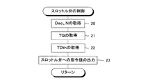
- the fuel supply means of the above invention is not particularly limited, and is, for example, a fuel injection valve. Further, the air supply amount control means of the above invention is not particularly limited, and is, for example, a throttle valve.
- An exhaust gas recirculation device is provided for recirculating exhaust gas discharged from the combustion chamber into the exhaust passage to the intake passage, and the exhaust gas recirculation device controls the amount of exhaust gas recirculated to the intake passage.
- the air supply amount control means of the invention may be a recirculation exhaust gas amount control valve.
- the turbocharger includes a supercharger including an exhaust turbine disposed in the exhaust passage and a compressor disposed in the intake passage, and the supercharger has a vane for controlling the compressive force of air by the compressor in the exhaust turbine.
- the air supply amount control means of the above invention may be a vane.
- the air amount detection means of the present invention is not particularly limited, but is, for example, an air flow meter disposed in the intake passage.
- the air-fuel ratio detecting means of the present invention is not particularly limited, but is an oxygen concentration sensor, for example.
- the air-fuel ratio error of the present invention may be any value as long as it indicates a value of the estimated air-fuel ratio relative to the detected air-fuel ratio. For example, it corresponds to an error calculated by subtracting 1 from the ratio of the estimated air-fuel ratio to the detected air-fuel ratio. Value.
- the estimated fuel supply amount correction value is calculated as a value that makes the error equivalent value zero.
- the method for obtaining the fuel supply error rate and the air amount detection error rate is not particularly limited. For example, it is preferable that these are obtained as follows. That is, the estimated fuel supply amount corrected by the fuel supply error compensation correction value and the air amount detection error when the fuel supply unit has a fuel supply error and the air amount detection unit has no air amount detection error.
- the amount of the specific component in the exhaust gas discharged from the combustion chamber when the air-fuel ratio control is executed using the detected air amount or the air supply command value that is not corrected by the compensation correction value is the first specific component amount. Get as.
- the fuel supply means has a fuel supply error and the air quantity detection means has no air quantity detection error, and the estimated fuel supply quantity not corrected by the fuel supply error compensation correction value and the air quantity
- the amount of the specific component in the exhaust gas discharged from the combustion chamber when the air-fuel ratio control is executed using the detected air amount or the air supply command value corrected by the detection error compensation correction value is the second specific component. Taken as a quantity. Further, the estimated fuel supply amount corrected by the fuel supply error compensation correction value and the air amount detection error when the fuel supply unit has no fuel supply error and the air amount detection unit has an air amount detection error.
- the amount of the specific component in the exhaust gas discharged from the combustion chamber when the air-fuel ratio control is executed using the detected air amount or the air supply command value not corrected by the compensation correction value is the third specific component amount. Get as. Further, the estimated fuel supply amount and the air amount detection that are not corrected by the fuel supply error compensation correction value even when the fuel supply unit has no fuel supply error and the air amount detection unit has an air amount detection error.
- the amount of the specific component in the exhaust gas discharged from the combustion chamber when the air-fuel ratio control is executed using the detected air amount or the air supply command value corrected by the error compensation correction value is the fourth specific component amount. Get as. Then, it is preferable that the fuel supply error ratio and the air amount detection error ratio are obtained based on the acquired four specific component amounts.
- the fuel supply means has a fuel supply error (for example, a drawing tolerance in manufacturing the fuel supply means), and the air amount detection means has an air amount detection error (for example, in manufacturing the air amount detection means). If there is a drawing tolerance), the fuel supply error rate and the air amount detection error rate corresponding to the fuel supply error of the fuel supply unit and the air amount detection error of the air amount detection unit are used for air-fuel ratio control. Therefore, since the air-fuel ratio control is executed in consideration of the fuel supply error of the fuel supply means and the air amount detection error of the air amount detection means, a higher effect can be obtained as the expected effect obtained by the air-fuel ratio control. Can do.
- a fuel supply error for example, a drawing tolerance in manufacturing the fuel supply means
- the air amount detection means has an air amount detection error (for example, in manufacturing the air amount detection means). If there is a drawing tolerance), the fuel supply error rate and the air amount detection error rate corresponding to the fuel supply error of the fuel supply unit and the air amount detection error of the air amount detection unit are used for air
- the fuel supply error rate and the air amount detection error rate are obtained as follows. That is, when the fuel supply means has a fuel supply error, the air amount detection means has no air amount detection error, and the air-fuel ratio detection means has no air-fuel ratio detection error, the fuel supply error compensation correction value is used. Exhaust gas discharged from the combustion chamber when the air-fuel ratio control is executed using the corrected estimated fuel supply amount and the detected air amount or the air supply command value not corrected by the air amount detection error compensation correction value The amount of the specific component in the gas is acquired as the first specific component amount.
- the fuel supply error compensation correction value may be used when the fuel supply means has a fuel supply error, the air quantity detection means has no air quantity detection error, and the air-fuel ratio detection means has no air-fuel ratio detection error. Exhaust gas discharged from the combustion chamber when the air-fuel ratio control is executed using the uncorrected estimated fuel supply amount and the detected air amount or air supply command value corrected by the air amount detection error compensation correction value The amount of the specific component in the gas is acquired as the second specific component amount.
- the fuel supply error compensation correction value may be used when the fuel supply means has no fuel supply error, the air quantity detection means has an air quantity detection error, and the air-fuel ratio detection means has no air-fuel ratio detection error.
- Exhaust gas discharged from the combustion chamber when the air-fuel ratio control is executed using the corrected estimated fuel supply amount and the detected air amount or the air supply command value not corrected by the air amount detection error compensation correction value The amount of the specific component in the gas is acquired as the third specific component amount.
- the fuel supply error compensation correction value may be used when the fuel supply means has no fuel supply error, the air quantity detection means has an air quantity detection error, and the air-fuel ratio detection means has no air-fuel ratio detection error.
- Exhaust gas discharged from the combustion chamber when the air-fuel ratio control is executed using the uncorrected estimated fuel supply amount and the detected air amount or air supply command value corrected by the air amount detection error compensation correction value The amount of the specific component in the gas is acquired as the fourth specific component amount.
- the fuel supply error compensation correction value is obtained in a state where the fuel supply means has no fuel supply error, the air quantity detection means has no air quantity detection error, and the air-fuel ratio detection means has an air-fuel ratio detection error.
- Exhaust gas discharged from the combustion chamber when the air-fuel ratio control is executed using the corrected estimated fuel supply amount and the detected air amount or the air supply command value not corrected by the air amount detection error compensation correction value The amount of the specific component in the gas is acquired as the fifth specific component amount.
- the fuel supply error compensation correction value is obtained in a state where the fuel supply means has no fuel supply error, the air quantity detection means has no air quantity detection error, and the air-fuel ratio detection means has an air-fuel ratio detection error.
- Exhaust gas discharged from the combustion chamber when the air-fuel ratio control is executed using the uncorrected estimated fuel supply amount and the detected air amount or air supply command value corrected by the air amount detection error compensation correction value The amount of the specific component in the gas is acquired as the sixth specific component amount. Then, it is preferable that the fuel supply error ratio and the air amount detection error ratio are obtained based on the obtained six specific component amounts.
- the fuel supply means has a fuel supply error (for example, drawing tolerance in manufacturing the fuel supply means), and the air amount detection means has an air amount detection error (for example, in manufacturing the air amount detection means). If there is an air-fuel ratio detection error in the air-fuel ratio detection means (for example, a drawing tolerance in manufacturing the air-fuel ratio detection means), the fuel supply error of these fuel supply means and the air amount detection means The air amount detection error and the fuel supply error rate and the air amount detection error rate corresponding to the air / fuel ratio detection error of the air / fuel ratio detection means are used for air / fuel ratio control.
- a fuel supply error for example, drawing tolerance in manufacturing the fuel supply means
- the air amount detection means has an air amount detection error (for example, in manufacturing the air amount detection means). If there is an air-fuel ratio detection error in the air-fuel ratio detection means (for example, a drawing tolerance in manufacturing the air-fuel ratio detection means), the fuel supply error of these fuel supply means and the air amount detection means.
- the air-fuel ratio control is executed in consideration of the fuel supply error of the fuel supply means, the air amount detection error of the air amount detection means, and the air-fuel ratio detection error of the air-fuel ratio detection means. A higher effect can be obtained as an expected effect.
- Another invention of the present application is a fuel supply means for supplying fuel to the combustion chamber, and a fuel supply means for supplying the fuel supply means with a fuel supply command value for causing the fuel supply means to supply a target amount of fuel to the combustion chamber.
- Command value applying means, and fuel supply amount estimating means for estimating the amount of fuel supplied from the fuel supply means to the combustion chamber based on the fuel supply command value supplied from the fuel supply command value applying means to the fuel supply means;
- An air supply amount control means for controlling the amount of air supplied to the combustion chamber, and an air supply command value for causing the air supply amount control means to supply a target amount of air to the combustion chamber.
- An air supply command value applying means for supplying, an air amount detecting means for detecting the amount of air supplied to the combustion chamber, an estimated fuel supply amount that is an amount of fuel estimated by the fuel supply amount estimating means, and the air amount detection Air-fuel ratio estimating means for estimating the air-fuel ratio of the air-fuel mixture formed in the combustion chamber based on the detected air supply amount that is the amount of air detected by the stage, and the air-fuel ratio of the air-fuel mixture formed in the combustion chamber
- An air-fuel ratio detecting means to detect, an estimated air-fuel ratio that is the air-fuel ratio estimated by the air-fuel ratio estimating means, and a detected air-fuel ratio that is the air-fuel ratio detected by the air-fuel ratio detecting means are mutually
- the present invention relates to a control device for an internal combustion engine comprising air-fuel ratio control means for executing air-fuel ratio control, which is control for matching, using a fuel supply command value and a detected air amount or an air supply command value.
- the control device of the present invention corrects the estimated air-fuel ratio to the detected air-fuel ratio by correcting the fuel supply command value given to the fuel supply means when the estimated air-fuel ratio does not match the detected air-fuel ratio.
- a correction value for correcting the fuel supply command value that is a correction value to be calculated is calculated based on an air-fuel ratio error that is an error of the estimated air-fuel ratio with respect to the detected air-fuel ratio, and is caused by the fuel supply error of the fuel supply means among the air-fuel ratio errors
- the ratio of the air-fuel ratio error to be obtained is acquired as the fuel supply error ratio
- the ratio of the air-fuel ratio error caused by the air amount detection error of the air amount detection means among the air-fuel ratio error is acquired as the air amount detection error ratio.
- Fuel that is a correction value for correcting the fuel supply command value by dividing the fuel supply command value correction correction value using the fuel supply error rate and the air amount detection error rate A supply error compensation correction value and an air amount detection error compensation correction value that is a correction value for correcting the detected air amount or the air supply command value are calculated and corrected by the fuel supply error compensation correction value.
- the air-fuel ratio control is executed using the fuel supply command value and the detected air amount or air supply command value corrected by the air amount detection error compensation correction value.
- the fuel supply error compensation correction value and the air amount detection error compensation correction value are used to have a value equivalent to the air-fuel ratio error. Is calculated as the air-fuel ratio error equivalent value so that the air-fuel ratio error equivalent value becomes equal to the air-fuel ratio error. It is divided into correction values for error compensation.
- the fuel supply error compensation correction value and the air amount detection error compensation correction value are set based on the air-fuel ratio error, which is an error in the estimated air-fuel ratio with respect to the detected air amount.
- the air-fuel ratio error equivalent value is calculated as the above-mentioned air-fuel ratio error (that is, fuel supply error compensation correction).
- the fuel supply error compensation correction value and the air amount detection error compensation correction value are set so as to be equal to the value and the value that forms the source of setting the air amount detection error compensation correction value.
- the air-fuel ratio control using the fuel supply error compensation correction value and the air amount detection error compensation correction value converts the air-fuel ratio error into the fuel injection error.
- the air-fuel ratio control is performed in a state where the air-fuel ratio error caused by the error and the air-fuel ratio error caused by the air amount detection error are appropriately distributed. Therefore, according to the present invention, a high effect can be obtained as an expected effect obtained by the air-fuel ratio control.
- the air-fuel ratio error of the present invention may be any value as long as it indicates an error in the estimated air-fuel ratio with respect to the detected air-fuel ratio. For example, it corresponds to an error calculated by subtracting 1 from the ratio of the estimated air-fuel ratio with respect to the detected air-fuel ratio. Value.
- the fuel supply command value correction value is calculated as a value that makes the error equivalent value zero.
- the method for obtaining the fuel supply error rate and the air amount detection error rate is not particularly limited. For example, it is preferable that these are obtained as follows. That is, the fuel supply command value corrected by the fuel supply error compensation correction value and the air amount detection error when the fuel supply unit has a fuel supply error and the air amount detection unit has no air amount detection error.
- the amount of the specific component in the exhaust gas discharged from the combustion chamber when the air-fuel ratio control is executed using the detected air amount or the air supply command value that is not corrected by the compensation correction value is the first specific component amount. Get as. Further, the fuel supply command value and the air amount detection that are not corrected by the fuel supply error compensation correction value even when the fuel supply unit has a fuel supply error and the air amount detection unit has no air amount detection error.
- the amount of the specific component in the exhaust gas discharged from the combustion chamber when the air-fuel ratio control is executed using the detected air amount or the air supply command value corrected by the error compensation correction value is the second specific component amount.
- the amount of the specific component in the exhaust gas discharged from the combustion chamber when the air-fuel ratio control is executed using the detected air amount or the air supply command value not corrected by the compensation correction value is the third specific component amount. Get as.
- the amount of the specific component in the exhaust gas discharged from the combustion chamber when the air-fuel ratio control is executed using the detected air amount or the air supply command value corrected by the error compensation correction value is the fourth specific component amount. Get as. Then, it is preferable that the fuel supply error ratio and the air amount detection error ratio are obtained based on the acquired four specific component amounts.
- the fuel supply means has a fuel supply error (for example, a drawing tolerance in manufacturing the fuel supply means), and the air amount detection means has an air amount detection error (for example, in manufacturing the air amount detection means). If there is a drawing tolerance), the fuel supply error rate and the air amount detection error rate corresponding to the fuel supply error of the fuel supply unit and the air amount detection error of the air amount detection unit are used for air-fuel ratio control. Therefore, since the air-fuel ratio control is executed in consideration of the fuel supply error of the fuel supply means and the air amount detection error of the air amount detection means, a higher effect can be obtained as the expected effect obtained by the air-fuel ratio control. Can do.
- a fuel supply error for example, a drawing tolerance in manufacturing the fuel supply means
- the air amount detection means has an air amount detection error (for example, in manufacturing the air amount detection means). If there is a drawing tolerance), the fuel supply error rate and the air amount detection error rate corresponding to the fuel supply error of the fuel supply unit and the air amount detection error of the air amount detection unit are used for air
- the fuel supply error rate and the air amount detection error rate are obtained as follows. That is, when the fuel supply means has a fuel supply error, the air amount detection means has no air amount detection error, and the air-fuel ratio detection means has no air-fuel ratio detection error, the fuel supply error compensation correction value is used. Exhaust gas discharged from the combustion chamber when the air-fuel ratio control is executed using the corrected fuel supply command value and the detected air amount or air supply command value not corrected by the air amount detection error compensation correction value The amount of the specific component in the gas is acquired as the first specific component amount.
- the fuel supply error compensation correction value may be used when the fuel supply means has a fuel supply error, the air quantity detection means has no air quantity detection error, and the air-fuel ratio detection means has no air-fuel ratio detection error. Exhaust gas discharged from the combustion chamber when the air-fuel ratio control is executed using the uncorrected fuel supply command value and the detected air amount or air supply command value corrected by the air amount detection error compensation correction value The amount of the specific component in the gas is acquired as the second specific component amount.
- the fuel supply error compensation correction value may be used when the fuel supply means has no fuel supply error, the air quantity detection means has an air quantity detection error, and the air-fuel ratio detection means has no air-fuel ratio detection error.
- Exhaust gas discharged from the combustion chamber when the air-fuel ratio control is executed using the corrected fuel supply command value and the detected air amount or air supply command value not corrected by the air amount detection error compensation correction value The amount of the specific component in the gas is acquired as the third specific component amount.
- the fuel supply error compensation correction value may be used when the fuel supply means has no fuel supply error, the air quantity detection means has an air quantity detection error, and the air-fuel ratio detection means has no air-fuel ratio detection error.
- Exhaust gas discharged from the combustion chamber when the air-fuel ratio control is executed using the uncorrected fuel supply command value and the detected air amount or air supply command value corrected by the air amount detection error compensation correction value The amount of the specific component in the gas is acquired as the fourth specific component amount.
- the fuel supply error compensation correction value is obtained in a state where the fuel supply means has no fuel supply error, the air quantity detection means has no air quantity detection error, and the air-fuel ratio detection means has an air-fuel ratio detection error.
- Exhaust gas discharged from the combustion chamber when the air-fuel ratio control is executed using the corrected fuel supply command value and the detected air amount or air supply command value not corrected by the air amount detection error compensation correction value The amount of the specific component in the gas is acquired as the third specific component amount.
- the fuel supply error compensation correction value is obtained in a state where the fuel supply means has no fuel supply error, the air quantity detection means has no air quantity detection error, and the air-fuel ratio detection means has an air-fuel ratio detection error.
- Exhaust gas discharged from the combustion chamber when the air-fuel ratio control is executed using the uncorrected fuel supply command value and the detected air amount or air supply command value corrected by the air amount detection error compensation correction value The amount of the specific component in the gas is acquired as the third specific component amount. Then, it is preferable that the fuel supply error ratio and the air amount detection error ratio are obtained based on the obtained six specific component amounts.
- the fuel supply means has a fuel supply error (for example, drawing tolerance in manufacturing the fuel supply means), and the air amount detection means has an air amount detection error (for example, in manufacturing the air amount detection means). If there is an air-fuel ratio detection error in the air-fuel ratio detection means (for example, a drawing tolerance in manufacturing the air-fuel ratio detection means), the fuel supply error of these fuel supply means and the air amount detection means The air amount detection error and the fuel supply error rate and the air amount detection error rate corresponding to the air / fuel ratio detection error of the air / fuel ratio detection means are used for air / fuel ratio control.
- a fuel supply error for example, drawing tolerance in manufacturing the fuel supply means
- the air amount detection means has an air amount detection error (for example, in manufacturing the air amount detection means). If there is an air-fuel ratio detection error in the air-fuel ratio detection means (for example, a drawing tolerance in manufacturing the air-fuel ratio detection means), the fuel supply error of these fuel supply means and the air amount detection means.
- the air-fuel ratio control is executed in consideration of the fuel supply error of the fuel supply means, the air amount detection error of the air amount detection means, and the air-fuel ratio detection error of the air-fuel ratio detection means. A higher effect can be obtained as an expected effect.
- a fuel supply means for supplying fuel to a combustion chamber and a fuel supply command value for causing the fuel supply means to supply a target amount of fuel to the combustion chamber by the fuel supply means.
- Supply command value giving means, and fuel supply amount estimating means for estimating the amount of fuel supplied from the fuel supply means to the combustion chamber based on the fuel supply command value given from the fuel supply command value giving means to the fuel supply means
- An air supply amount control means for controlling the amount of air supplied to the combustion chamber, and an air supply command control means for supplying an air supply command value for supplying a target amount of air to the combustion chamber by the air supply amount control means
- An air supply command value applying means for supplying to the combustion chamber, an air amount detecting means for detecting the amount of air supplied to the combustion chamber, an estimated fuel supply amount that is an amount of fuel estimated by the fuel supply amount estimating means, and the air
- An air-fuel ratio estimating means for estimating an air-fuel ratio of an air-fuel mixture formed in the combustion chamber based on a detected
- the control device of the present invention provides the estimated fuel supply amount estimated by the fuel supply amount estimation means and the fuel supply command value to be given to the fuel supply means.
- a correction value for correcting the estimated fuel supply amount / fuel supply command value which is a correction value that makes the estimated air-fuel ratio and the detected air-fuel ratio coincide with each other by correcting, is based on an air-fuel ratio error that is an error of the estimated air-fuel ratio with respect to the detected air-fuel ratio.
- the ratio of the air-fuel ratio error resulting from the fuel supply error of the fuel supply means of the air-fuel ratio error is obtained as the fuel supply error ratio and the air amount detection of the air amount detection means of the air-fuel ratio error is calculated
- the ratio of the air-fuel ratio error caused by the error is acquired as the air amount detection error rate, and the estimated fuel supply amount and the air amount detection error rate are obtained using the fuel supply error rate and the air amount detection error rate.
- the fuel supply error compensation correction value which is a correction value for correcting the estimated fuel supply amount and the fuel supply command value, and the detected air amount or the air supply command value are corrected by dividing the charge supply command value correction value.
- An air amount detection error compensation correction value which is a correction value for calculating the fuel supply error, is calculated, and the fuel corrected by the fuel supply error compensation correction value and the fuel supply error compensation correction value are corrected.
- the air-fuel ratio control is executed using the supply command value and the detected air amount or the air supply command value corrected by the correction value for air amount detection error compensation.
- the fuel supply error compensation correction value and the air amount detection error compensation correction value are used to have a value equivalent to the air-fuel ratio error.
- the estimated fuel supply amount / fuel supply command value correction correction value is the fuel supply error compensation correction value so that the air / fuel ratio error equivalent value becomes equal to the air / fuel ratio error.
- the air amount detection error compensation correction value is the fuel supply error compensation correction value so that the air / fuel ratio error equivalent value becomes equal to the air / fuel ratio error.
- the fuel supply error compensation correction value and the air amount detection error compensation correction value are set based on the air-fuel ratio error, which is an error in the estimated air-fuel ratio with respect to the detected air amount.
- the air-fuel ratio error equivalent value is calculated as the above-mentioned air-fuel ratio error (that is, fuel supply error compensation correction).
- the fuel supply error compensation correction value and the air amount detection error compensation correction value are set so as to be equal to the value and the value that forms the source of setting the air amount detection error compensation correction value.
- the air-fuel ratio control using the fuel supply error compensation correction value and the air amount detection error compensation correction value converts the air-fuel ratio error into the fuel injection error.
- the air-fuel ratio control is performed in a state where the air-fuel ratio error caused by the error and the air-fuel ratio error caused by the air amount detection error are appropriately distributed. Therefore, according to the present invention, a high effect can be obtained as an expected effect obtained by the air-fuel ratio control.
- the air-fuel ratio error of the present invention may be any value as long as it indicates a value of the estimated air-fuel ratio relative to the detected air-fuel ratio. Value.
- the estimated fuel supply amount / fuel supply command value correction value is calculated as a value that makes the error equivalent value zero.
- the method for obtaining the fuel supply error rate and the air amount detection error rate is not particularly limited. For example, it is preferable that these are obtained as follows. That is, the estimated fuel supply amount corrected by the fuel supply error compensation correction value and the fuel supply error compensation when the fuel supply unit has a fuel supply error and the air amount detection unit has no air amount detection error. From the combustion chamber when the air-fuel ratio control is executed using the fuel supply command value corrected by the correction value for use and the detected air amount or the air supply command value not corrected by the correction value for compensating the air amount detection error. The amount of the specific component in the exhaust gas discharged is acquired as the first specific component amount.
- the estimated fuel supply amount and the fuel supply error which are not corrected by the fuel supply error compensation correction value when the fuel supply unit has a fuel supply error and the air amount detection unit has no air amount detection error Combustion chamber when the air-fuel ratio control is executed using the fuel supply command value not corrected by the compensation correction value and the detected air amount or air supply command value corrected by the air amount detection error compensation correction value
- the amount of the specific component in the exhaust gas discharged from is acquired as the second specific component amount.
- the air-fuel ratio control is executed using the fuel supply command value corrected by the correction value for use and the detected air amount or the air supply command value not corrected by the correction value for compensating the air amount detection error.
- the amount of the specific component in the exhaust gas discharged is acquired as the third specific component amount.
- Combustion chamber when the air-fuel ratio control is executed using the fuel supply command value not corrected by the compensation correction value and the detected air amount or air supply command value corrected by the air amount detection error compensation correction value
- the amount of the specific component in the exhaust gas discharged from is acquired as the fourth specific component amount. Then, it is preferable that the fuel supply error ratio and the air amount detection error ratio are obtained based on the acquired four specific component amounts.
- the fuel supply means has a fuel supply error (for example, a drawing tolerance in manufacturing the fuel supply means), and the air amount detection means has an air amount detection error (for example, in manufacturing the air amount detection means). If there is a drawing tolerance), the fuel supply error rate and the air amount detection error rate corresponding to the fuel supply error of the fuel supply unit and the air amount detection error of the air amount detection unit are used for air-fuel ratio control. Therefore, since the air-fuel ratio control is executed in consideration of the fuel supply error of the fuel supply means and the air amount detection error of the air amount detection means, a higher effect can be obtained as the expected effect obtained by the air-fuel ratio control. Can do.
- a fuel supply error for example, a drawing tolerance in manufacturing the fuel supply means
- the air amount detection means has an air amount detection error (for example, in manufacturing the air amount detection means). If there is a drawing tolerance), the fuel supply error rate and the air amount detection error rate corresponding to the fuel supply error of the fuel supply unit and the air amount detection error of the air amount detection unit are used for air
- the fuel supply error rate and the air amount detection error rate are obtained as follows. That is, when the fuel supply means has a fuel supply error, the air amount detection means has no air amount detection error, and the air-fuel ratio detection means has no air-fuel ratio detection error, the fuel supply error compensation correction value is used. Using the corrected estimated fuel supply amount, the fuel supply command value corrected by the fuel supply error compensation correction value, and the detected air amount or air supply command value not corrected by the air amount detection error compensation correction value Then, the amount of the specific component in the exhaust gas discharged from the combustion chamber when the air-fuel ratio control is executed is acquired as the first specific component amount.
- the fuel supply error compensation correction value may be used when the fuel supply means has a fuel supply error, the air quantity detection means has no air quantity detection error, and the air-fuel ratio detection means has no air-fuel ratio detection error.
- the amount of the specific component in the exhaust gas discharged from the combustion chamber when the air-fuel ratio control is executed using is acquired as the second specific component amount.
- the fuel supply error compensation correction value may be used when the fuel supply means has no fuel supply error, the air quantity detection means has an air quantity detection error, and the air-fuel ratio detection means has no air-fuel ratio detection error.
- the fuel supply error compensation correction value may be used when the fuel supply means has no fuel supply error, the air quantity detection means has an air quantity detection error, and the air-fuel ratio detection means has no air-fuel ratio detection error.
- the amount of the specific component in the exhaust gas discharged from the combustion chamber when the air-fuel ratio control is executed using is acquired as the fourth specific component amount.
- the fuel supply error compensation correction value is obtained in a state where the fuel supply means has no fuel supply error, the air quantity detection means has no air quantity detection error, and the air-fuel ratio detection means has an air-fuel ratio detection error.
- the fuel supply command value corrected by the fuel supply error compensation correction value, and the detected air amount or air supply command value not corrected by the air amount detection error compensation correction value is acquired as the fifth specific component amount. Further, the fuel supply error compensation correction value is obtained in a state where the fuel supply means has no fuel supply error, the air quantity detection means has no air quantity detection error, and the air-fuel ratio detection means has an air-fuel ratio detection error.
- the amount of the specific component in the exhaust gas discharged from the combustion chamber when the air-fuel ratio control is executed using is acquired as the sixth specific component amount. Then, it is preferable that the fuel supply error ratio and the air amount detection error ratio are obtained based on the obtained six specific component amounts.
- the fuel supply means has a fuel supply error (for example, drawing tolerance in manufacturing the fuel supply means), and the air amount detection means has an air amount detection error (for example, in manufacturing the air amount detection means). If there is an air-fuel ratio detection error in the air-fuel ratio detection means (for example, a drawing tolerance in manufacturing the air-fuel ratio detection means), the fuel supply error of these fuel supply means and the air amount detection means The air amount detection error and the fuel supply error rate and the air amount detection error rate corresponding to the air / fuel ratio detection error of the air / fuel ratio detection means are used for air / fuel ratio control.
- a fuel supply error for example, drawing tolerance in manufacturing the fuel supply means
- the air amount detection means has an air amount detection error (for example, in manufacturing the air amount detection means). If there is an air-fuel ratio detection error in the air-fuel ratio detection means (for example, a drawing tolerance in manufacturing the air-fuel ratio detection means), the fuel supply error of these fuel supply means and the air amount detection means.
- the air-fuel ratio control is executed in consideration of the fuel supply error of the fuel supply means, the air amount detection error of the air amount detection means, and the air-fuel ratio detection error of the air-fuel ratio detection means. A higher effect can be obtained as an expected effect.
- a fuel supply means for supplying fuel to a combustion chamber and a fuel supply command value for causing the fuel supply means to supply a target amount of fuel to the combustion chamber by the fuel supply means.
- Supply command value giving means, and fuel supply amount estimating means for estimating the amount of fuel supplied from the fuel supply means to the combustion chamber based on the fuel supply command value given from the fuel supply command value giving means to the fuel supply means
- An air supply amount control means for controlling the amount of air supplied to the combustion chamber, and an air supply command control means for supplying an air supply command value for supplying a target amount of air to the combustion chamber by the air supply amount control means
- An air supply command value applying means for supplying to the combustion chamber, an air amount detecting means for detecting the amount of air supplied to the combustion chamber, an estimated fuel supply amount that is an amount of fuel estimated by the fuel supply amount estimating means, and the air
- An air-fuel ratio estimating means for estimating an air-fuel ratio of an air-fuel mixture formed in the combustion chamber based on a detected
- the control device of the present invention corrects the detected air amount detected by the air amount detecting means when the estimated air fuel ratio and the detected air fuel ratio do not match each other, thereby correcting the estimated air fuel ratio and the detected air fuel ratio.
- a correction value for correcting the detected air amount which is a correction value to be matched with each other, is calculated based on an air-fuel ratio error that is an error of the estimated air-fuel ratio with respect to the detected air-fuel ratio.
- the estimated fuel supply amount or the fuel supply command value is corrected by dividing the correction value for correcting the detected air amount using the fuel supply error rate and the air amount detection error rate.
- a correction value for compensating the fuel supply error which is a correction value for calculating the correction value
- a correction value for compensating the air amount detection error which is a correction value for correcting the detected air amount, are corrected by the correction value for compensating the fuel supply error.
- the air-fuel ratio control is executed using the estimated fuel supply amount or fuel supply command value and the detected air amount corrected by the correction value for air amount detection error compensation.
- the fuel supply error compensation correction value and the air amount detection error compensation correction value are used to have a value equivalent to the air-fuel ratio error.
- the detected air amount correction correction value and the fuel supply error compensation correction value and the air amount detection error are set so that the air-fuel ratio error equivalent value becomes equal to the air-fuel ratio error. It is divided into compensation correction values.
- the fuel supply error compensation correction value and the air amount detection error compensation correction value are set based on the air-fuel ratio error, which is an error in the estimated air-fuel ratio with respect to the detected air amount.
- the air-fuel ratio error equivalent value is calculated as the above-mentioned air-fuel ratio error (that is, fuel supply error compensation correction).
- the fuel supply error compensation correction value and the air amount detection error compensation correction value are set so as to be equal to the value and the value that forms the source of setting the air amount detection error compensation correction value.
- the air-fuel ratio control using the fuel supply error compensation correction value and the air amount detection error compensation correction value converts the air-fuel ratio error into the fuel injection error.
- the air-fuel ratio control is performed in a state where the air-fuel ratio error caused by the error and the air-fuel ratio error caused by the air amount detection error are appropriately distributed. Therefore, according to the present invention, a high effect can be obtained as an expected effect obtained by the air-fuel ratio control.
- the air-fuel ratio error of the present invention may be any value as long as it indicates a value of the estimated air-fuel ratio relative to the detected air-fuel ratio. Value.
- the correction value for correcting the detected air amount is calculated as a value that makes the error equivalent value zero.
- the method for obtaining the fuel supply error rate and the air amount detection error rate is not particularly limited. For example, it is preferable that these are obtained as follows. That is, the estimated fuel supply amount or the fuel supply command value corrected by the fuel supply error compensation correction value in a state where the fuel supply means has a fuel supply error and the air amount detection means has no air amount detection error.
- the amount of the specific component in the exhaust gas discharged from the combustion chamber when the air-fuel ratio control is executed using the detected air amount that is not corrected by the correction value for air amount detection error compensation is the first specific component amount. Get as. Further, the estimated fuel supply amount or the fuel supply command value not corrected by the fuel supply error compensation correction value when the fuel supply means has a fuel supply error and the air amount detection means has no air amount detection error.
- the amount of the specific component in the exhaust gas discharged from the combustion chamber when the air-fuel ratio control is executed using the detected air amount corrected by the correction value for compensating the air amount detection error is the second specific component amount Get as.
- the amount of the specific component in the exhaust gas discharged from the combustion chamber when the air-fuel ratio control is executed using the detected air amount that is not corrected by the correction value for air amount detection error compensation is the third specific component amount. Get as.
- the estimated fuel supply amount or the fuel supply command value not corrected by the fuel supply error compensation correction value when the fuel supply means has no fuel supply error and the air amount detection means has an air amount detection error is the fourth specific component amount Get as. Then, it is preferable that the fuel supply error ratio and the air amount detection error ratio are obtained based on the acquired four specific component amounts.
- the fuel supply means has a fuel supply error (for example, a drawing tolerance in manufacturing the fuel supply means), and the air amount detection means has an air amount detection error (for example, in manufacturing the air amount detection means). If there is a drawing tolerance), the fuel supply error rate and the air amount detection error rate corresponding to the fuel supply error of the fuel supply unit and the air amount detection error of the air amount detection unit are used for air-fuel ratio control. Therefore, since the air-fuel ratio control is executed in consideration of the fuel supply error of the fuel supply means and the air amount detection error of the air amount detection means, a higher effect can be obtained as the expected effect obtained by the air-fuel ratio control. Can do.
- a fuel supply error for example, a drawing tolerance in manufacturing the fuel supply means
- the air amount detection means has an air amount detection error (for example, in manufacturing the air amount detection means). If there is a drawing tolerance), the fuel supply error rate and the air amount detection error rate corresponding to the fuel supply error of the fuel supply unit and the air amount detection error of the air amount detection unit are used for air
- the fuel supply error rate and the air amount detection error rate are obtained as follows. That is, when the fuel supply means has a fuel supply error, the air amount detection means has no air amount detection error, and the air-fuel ratio detection means has no air-fuel ratio detection error, the fuel supply error compensation correction value is used. Exhaust gas discharged from the combustion chamber when the air-fuel ratio control is executed using the corrected estimated fuel supply amount or fuel supply command value and the detected air amount not corrected by the air amount detection error compensation correction value The amount of the specific component in the gas is acquired as the first specific component amount.
- the fuel supply error compensation correction value may be used when the fuel supply means has a fuel supply error, the air quantity detection means has no air quantity detection error, and the air-fuel ratio detection means has no air-fuel ratio detection error. Exhaust gas discharged from the combustion chamber when the air-fuel ratio control is executed using an uncorrected estimated fuel supply amount or fuel supply command value and a detected air amount corrected by the correction value for air amount detection error compensation The amount of the specific component in the gas is acquired as the second specific component amount.
- the fuel supply error compensation correction value may be used when the fuel supply means has no fuel supply error, the air quantity detection means has an air quantity detection error, and the air-fuel ratio detection means has no air-fuel ratio detection error.
- Exhaust gas discharged from the combustion chamber when the air-fuel ratio control is executed using the corrected estimated fuel supply amount or fuel supply command value and the detected air amount not corrected by the air amount detection error compensation correction value The amount of the specific component in the gas is acquired as the third specific component amount.
- the fuel supply error compensation correction value may be used when the fuel supply means has no fuel supply error, the air quantity detection means has an air quantity detection error, and the air-fuel ratio detection means has no air-fuel ratio detection error.
- Exhaust gas discharged from the combustion chamber when the air-fuel ratio control is executed using an uncorrected estimated fuel supply amount or fuel supply command value and a detected air amount corrected by the correction value for air amount detection error compensation The amount of the specific component in the gas is acquired as the fourth specific component amount.
- the fuel supply error compensation correction value is obtained in a state where the fuel supply means has no fuel supply error, the air quantity detection means has no air quantity detection error, and the air-fuel ratio detection means has an air-fuel ratio detection error.
- Exhaust gas discharged from the combustion chamber when the air-fuel ratio control is executed using the corrected estimated fuel supply amount or fuel supply command value and the detected air amount not corrected by the air amount detection error compensation correction value The amount of the specific component in the gas is acquired as the fifth specific component amount.
- the fuel supply error compensation correction value is obtained in a state where the fuel supply means has no fuel supply error, the air quantity detection means has no air quantity detection error, and the air-fuel ratio detection means has an air-fuel ratio detection error.
- Exhaust gas discharged from the combustion chamber when the air-fuel ratio control is executed using an uncorrected estimated fuel supply amount or fuel supply command value and a detected air amount corrected by the correction value for air amount detection error compensation The amount of the specific component in the gas is acquired as the sixth specific component amount. Then, it is preferable that the fuel supply error ratio and the air amount detection error ratio are obtained based on the obtained six specific component amounts.
- the fuel supply means has a fuel supply error (for example, drawing tolerance in manufacturing the fuel supply means), and the air amount detection means has an air amount detection error (for example, in manufacturing the air amount detection means). If there is an air-fuel ratio detection error in the air-fuel ratio detection means (for example, a drawing tolerance in manufacturing the air-fuel ratio detection means), the fuel supply error of these fuel supply means and the air amount detection means The air amount detection error and the fuel supply error rate and the air amount detection error rate corresponding to the air / fuel ratio detection error of the air / fuel ratio detection means are used for air / fuel ratio control.
- a fuel supply error for example, drawing tolerance in manufacturing the fuel supply means
- the air amount detection means has an air amount detection error (for example, in manufacturing the air amount detection means). If there is an air-fuel ratio detection error in the air-fuel ratio detection means (for example, a drawing tolerance in manufacturing the air-fuel ratio detection means), the fuel supply error of these fuel supply means and the air amount detection means.
- the air-fuel ratio control is executed in consideration of the fuel supply error of the fuel supply means, the air amount detection error of the air amount detection means, and the air-fuel ratio detection error of the air-fuel ratio detection means. A higher effect can be obtained as an expected effect.
- a fuel supply means for supplying fuel to a combustion chamber and a fuel supply command value for causing the fuel supply means to supply a target amount of fuel to the combustion chamber by the fuel supply means.
- Supply command value giving means, and fuel supply amount estimating means for estimating the amount of fuel supplied from the fuel supply means to the combustion chamber based on the fuel supply command value given from the fuel supply command value giving means to the fuel supply means
- An air supply amount control means for controlling the amount of air supplied to the combustion chamber, and an air supply command control means for supplying an air supply command value for supplying a target amount of air to the combustion chamber by the air supply amount control means
- An air supply command value applying means for supplying to the combustion chamber, an air amount detecting means for detecting the amount of air supplied to the combustion chamber, an estimated fuel supply amount that is an amount of fuel estimated by the fuel supply amount estimating means, and the air
- An air-fuel ratio estimating means for estimating an air-fuel ratio of an air-fuel mixture formed in the combustion chamber based on a detected
- the control device of the present invention corrects the estimated air-fuel ratio and the detected air-fuel ratio by correcting the air supply command value given to the air supply amount control means when the estimated air-fuel ratio and the detected air-fuel ratio do not match each other.
- a correction value for correcting the air supply command value which is a correction value to be matched with each other, is calculated based on an air-fuel ratio error that is an error of the estimated air-fuel ratio with respect to the detected air-fuel ratio, and among the air-fuel ratio errors, the fuel supply error of the fuel supply means
- the ratio of the air-fuel ratio error caused by the air-fuel ratio error is obtained as the fuel supply error ratio
- the ratio of the air-fuel ratio error caused by the air quantity detection error of the air quantity detection means is obtained as the air quantity detection error ratio.
- the estimated fuel supply amount or the fuel supply command value is compensated by dividing the correction value for correcting the air supply command value using the fuel supply error rate and the air amount detection error rate.
- a fuel supply error compensation correction value which is a correction value for correcting the air supply command value
- an air amount detection error compensation correction value which is a correction value for correcting the air supply command value
- the fuel supply error compensation correction value and the air amount detection error compensation correction value are used to have a value equivalent to the air-fuel ratio error.
- the air supply command value correction correction value and the fuel supply error compensation correction value and the air amount detection are set so that the air fuel ratio error equivalent value becomes equal to the air fuel ratio error. It is divided into correction values for error compensation.
- the fuel supply error compensation correction value and the air amount detection error compensation correction value are set based on the air-fuel ratio error, which is an error in the estimated air-fuel ratio with respect to the detected air amount.
- the air-fuel ratio error equivalent value is calculated as the above-mentioned air-fuel ratio error (that is, fuel supply error compensation correction).
- the fuel supply error compensation correction value and the air amount detection error compensation correction value are set so as to be equal to the value and the value that forms the source of setting the air amount detection error compensation correction value.
- the air-fuel ratio control using the fuel supply error compensation correction value and the air amount detection error compensation correction value converts the air-fuel ratio error into the fuel injection error.
- the air-fuel ratio control is performed in a state where the air-fuel ratio error caused by the error and the air-fuel ratio error caused by the air amount detection error are appropriately distributed. Therefore, according to the present invention, a high effect can be obtained as an expected effect obtained by the air-fuel ratio control.
- the air-fuel ratio error of the present invention may be any value as long as it indicates a value of the estimated air-fuel ratio relative to the detected air-fuel ratio. Value.
- the air supply command value correction value is calculated as a value that makes the error equivalent value zero.
- the method for obtaining the fuel supply error rate and the air amount detection error rate is not particularly limited. For example, it is preferable that these are obtained as follows. That is, the estimated fuel supply amount or the fuel supply command value corrected by the fuel supply error compensation correction value in a state where the fuel supply means has a fuel supply error and the air amount detection means has no air amount detection error.
- the amount of the specific component in the exhaust gas discharged from the combustion chamber when the air-fuel ratio control is executed using the air supply command value that is not corrected by the air amount detection error compensation correction value is the first specific component Taken as a quantity. Further, the estimated fuel supply amount or the fuel supply command value not corrected by the fuel supply error compensation correction value when the fuel supply means has a fuel supply error and the air amount detection means has no air amount detection error.
- the amount of the specific component in the exhaust gas discharged from the combustion chamber when the air-fuel ratio control is executed using the air supply command value corrected by the air amount detection error compensation correction value is the second specific component Taken as a quantity.
- the amount of the specific component in the exhaust gas discharged from the combustion chamber when the air-fuel ratio control is executed using the air supply command value not corrected by the air amount detection error compensation correction value is the third specific component. Taken as a quantity.
- the estimated fuel supply amount or the fuel supply command value not corrected by the fuel supply error compensation correction value when the fuel supply means has no fuel supply error and the air amount detection means has an air amount detection error is the fourth specific component Taken as a quantity. Then, it is preferable that the fuel supply error ratio and the air amount detection error ratio are obtained based on the acquired four specific component amounts.
- the fuel supply means has a fuel supply error (for example, a drawing tolerance in manufacturing the fuel supply means), and the air amount detection means has an air amount detection error (for example, in manufacturing the air amount detection means). If there is a drawing tolerance), the fuel supply error rate and the air amount detection error rate corresponding to the fuel supply error of the fuel supply unit and the air amount detection error of the air amount detection unit are used for air-fuel ratio control. Therefore, since the air-fuel ratio control is executed in consideration of the fuel supply error of the fuel supply means and the air amount detection error of the air amount detection means, a higher effect can be obtained as the expected effect obtained by the air-fuel ratio control. Can do.
- a fuel supply error for example, a drawing tolerance in manufacturing the fuel supply means
- the air amount detection means has an air amount detection error (for example, in manufacturing the air amount detection means). If there is a drawing tolerance), the fuel supply error rate and the air amount detection error rate corresponding to the fuel supply error of the fuel supply unit and the air amount detection error of the air amount detection unit are used for air
- the fuel supply error rate and the air amount detection error rate are obtained as follows. That is, when the fuel supply means has a fuel supply error, the air amount detection means has no air amount detection error, and the air-fuel ratio detection means has no air-fuel ratio detection error, the fuel supply error compensation correction value is used.
- the air-fuel ratio control is executed using the corrected estimated fuel supply amount or fuel supply command value and the air supply command value not corrected by the air amount detection error compensation correction value, the fuel is discharged from the combustion chamber.
- the amount of the specific component in the exhaust gas is acquired as the first specific component amount.
- the fuel supply error compensation correction value may be used when the fuel supply means has a fuel supply error, the air quantity detection means has no air quantity detection error, and the air-fuel ratio detection means has no air-fuel ratio detection error.
- the air-fuel ratio control is executed using the estimated fuel supply amount that is not corrected or the fuel supply command value and the air supply command value that is corrected by the correction value for compensating the air amount detection error, the fuel is discharged from the combustion chamber.
- the amount of the specific component in the exhaust gas is acquired as the second specific component amount.
- the fuel supply error compensation correction value may be used when the fuel supply means has no fuel supply error, the air quantity detection means has an air quantity detection error, and the air-fuel ratio detection means has no air-fuel ratio detection error.
- the air-fuel ratio control is executed using the corrected estimated fuel supply amount or fuel supply command value and the air supply command value not corrected by the air amount detection error compensation correction value, the fuel is discharged from the combustion chamber.
- the amount of the specific component in the exhaust gas is acquired as the third specific component amount.
- the fuel supply error compensation correction value may be used when the fuel supply means has no fuel supply error, the air quantity detection means has an air quantity detection error, and the air-fuel ratio detection means has no air-fuel ratio detection error.
- the air-fuel ratio control is executed using the estimated fuel supply amount that is not corrected or the fuel supply command value and the air supply command value that is corrected by the correction value for compensating the air amount detection error, the fuel is discharged from the combustion chamber.
- the amount of the specific component in the exhaust gas is acquired as the fourth specific component amount. Further, the fuel supply error compensation correction value is obtained in a state where the fuel supply means has no fuel supply error, the air quantity detection means has no air quantity detection error, and the air-fuel ratio detection means has an air-fuel ratio detection error.
- the air-fuel ratio control is executed using the corrected estimated fuel supply amount or fuel supply command value and the air supply command value not corrected by the air amount detection error compensation correction value, the fuel is discharged from the combustion chamber.
- the amount of the specific component in the exhaust gas is acquired as the fifth specific component amount.
- the fuel supply error compensation correction value is obtained in a state where the fuel supply means has no fuel supply error, the air quantity detection means has no air quantity detection error, and the air-fuel ratio detection means has an air-fuel ratio detection error.
- the air-fuel ratio control is executed using the estimated fuel supply amount that is not corrected or the fuel supply command value and the air supply command value that is corrected by the correction value for compensating the air amount detection error, the fuel is discharged from the combustion chamber.
- the amount of the specific component in the exhaust gas is acquired as the sixth specific component amount. Then, it is preferable that the fuel supply error ratio and the air amount detection error ratio are obtained based on the obtained six specific component amounts.
- the fuel supply means has a fuel supply error (for example, drawing tolerance in manufacturing the fuel supply means), and the air amount detection means has an air amount detection error (for example, in manufacturing the air amount detection means). If there is an air-fuel ratio detection error in the air-fuel ratio detection means (for example, a drawing tolerance in manufacturing the air-fuel ratio detection means), the fuel supply error of these fuel supply means and the air amount detection means The air amount detection error and the fuel supply error rate and the air amount detection error rate corresponding to the air / fuel ratio detection error of the air / fuel ratio detection means are used for air / fuel ratio control.
- a fuel supply error for example, drawing tolerance in manufacturing the fuel supply means
- the air amount detection means has an air amount detection error (for example, in manufacturing the air amount detection means). If there is an air-fuel ratio detection error in the air-fuel ratio detection means (for example, a drawing tolerance in manufacturing the air-fuel ratio detection means), the fuel supply error of these fuel supply means and the air amount detection means.
- the air-fuel ratio control is executed in consideration of the fuel supply error of the fuel supply means, the air amount detection error of the air amount detection means, and the air-fuel ratio detection error of the air-fuel ratio detection means. A higher effect can be obtained as an expected effect.
- a fuel supply means for supplying fuel to a combustion chamber and a fuel supply command value for causing the fuel supply means to supply a target amount of fuel to the combustion chamber by the fuel supply means.
- Supply command value giving means, and fuel supply amount estimating means for estimating the amount of fuel supplied from the fuel supply means to the combustion chamber based on the fuel supply command value given from the fuel supply command value giving means to the fuel supply means
- An air supply amount control means for controlling the amount of air supplied to the combustion chamber, and an air supply command control means for supplying an air supply command value for supplying a target amount of air to the combustion chamber by the air supply amount control means
- An air supply command value applying means for supplying to the combustion chamber, an air amount detecting means for detecting the amount of air supplied to the combustion chamber, an estimated fuel supply amount that is an amount of fuel estimated by the fuel supply amount estimating means, and the air
- An air-fuel ratio estimating means for estimating an air-fuel ratio of an air-fuel mixture formed in the combustion chamber based on a detected
- the control device of the present invention provides a detected air amount detected by the air amount detecting means and an air supply command value to be given to the air supply amount control means when the estimated air fuel ratio and the detected air fuel ratio do not match each other.
- a correction value for correcting the detected air amount / air supply command value which is a correction value for making the estimated air-fuel ratio and the detected air-fuel ratio coincide with each other, is calculated based on the air-fuel ratio error that is the error of the estimated air-fuel ratio with respect to the detected air-fuel ratio.
- the ratio of the air-fuel ratio error caused by the fuel supply error of the fuel supply means in the air-fuel ratio error is acquired as the fuel supply error ratio
- the air amount detection error of the air amount detection means in the air-fuel ratio error The ratio of the resulting air-fuel ratio error is acquired as the air amount detection error rate
- the detected air amount / air supply command value is obtained using the fuel supply error rate and the air amount detection error rate.
- a fuel supply error compensation correction value that is a correction value for correcting the estimated fuel supply amount or the fuel supply command value by dividing the correct correction value, and a correction for correcting the detected air amount and the air supply command value
- a correction value for compensating the air amount detection error which is a value, is calculated and corrected by the estimated fuel supply amount or fuel supply command value corrected by the correction value for fuel supply error compensation and the correction value for air amount detection error compensation.
- the air-fuel ratio control is executed using the detected air amount and the air supply command value corrected by the air amount detection error compensation correction value.
- the fuel supply error compensation correction value and the air amount detection error compensation correction value are used to have a value equivalent to the air-fuel ratio error.
- the detected air amount / air supply command value correction value is set to the fuel supply error compensation correction value so that the air-fuel ratio error equivalent value becomes equal to the air-fuel ratio error.
- the air amount detection error compensation correction value is divided.
- the fuel supply error compensation correction value and the air amount detection error compensation correction value are set based on the air-fuel ratio error, which is an error in the estimated air-fuel ratio with respect to the detected air amount.
- the air-fuel ratio error equivalent value is calculated as the above-mentioned air-fuel ratio error (that is, fuel supply error compensation correction).
- the fuel supply error compensation correction value and the air amount detection error compensation correction value are set so as to be equal to the value and the value that forms the source of setting the air amount detection error compensation correction value.
- the air-fuel ratio control using the fuel supply error compensation correction value and the air amount detection error compensation correction value converts the air-fuel ratio error into the fuel injection error.
- the air-fuel ratio control is performed in a state where the air-fuel ratio error caused by the error and the air-fuel ratio error caused by the air amount detection error are appropriately distributed. Therefore, according to the present invention, a high effect can be obtained as an expected effect obtained by the air-fuel ratio control.
- the air-fuel ratio error of the present invention may be any value as long as it indicates a value of the estimated air-fuel ratio relative to the detected air-fuel ratio. Value.
- the detected air amount / air supply command value correction value is calculated as a value that makes the error equivalent value zero.
- the method for obtaining the fuel supply error rate and the air amount detection error rate is not particularly limited. For example, it is preferable that these are obtained as follows. That is, the estimated fuel supply amount or the fuel supply command value corrected by the fuel supply error compensation correction value in a state where the fuel supply means has a fuel supply error and the air amount detection means has no air amount detection error. Combustion when the air-fuel ratio control is executed using the detected air amount not corrected by the air amount detection error compensation correction value and the air supply command value not corrected by the air amount detection error compensation correction value The amount of the specific component in the exhaust gas discharged from the chamber is acquired as the first specific component amount.
- the estimated fuel supply amount or the fuel supply command value not corrected by the fuel supply error compensation correction value when the fuel supply means has a fuel supply error and the air amount detection means has no air amount detection error is estimated.
- the air-fuel ratio control is executed using the detected air amount corrected by the air amount detection error compensation correction value and the air supply command value corrected by the air amount detection error compensation correction value, the combustion chamber The amount of the specific component in the exhaust gas discharged from is acquired as the second specific component amount.
- the amount of the specific component in the exhaust gas discharged from the chamber is acquired as the third specific component amount. Further, the estimated fuel supply amount or the fuel supply command value not corrected by the fuel supply error compensation correction value when the fuel supply means has no fuel supply error and the air amount detection means has an air amount detection error.
- the combustion chamber The amount of the specific component in the exhaust gas discharged from is acquired as the fourth specific component amount. Then, it is preferable that the fuel supply error ratio and the air amount detection error ratio are obtained based on the acquired four specific component amounts.
- the fuel supply means has a fuel supply error (for example, a drawing tolerance in manufacturing the fuel supply means), and the air amount detection means has an air amount detection error (for example, in manufacturing the air amount detection means). If there is a drawing tolerance), the fuel supply error rate and the air amount detection error rate corresponding to the fuel supply error of the fuel supply unit and the air amount detection error of the air amount detection unit are used for air-fuel ratio control. Therefore, since the air-fuel ratio control is executed in consideration of the fuel supply error of the fuel supply means and the air amount detection error of the air amount detection means, a higher effect can be obtained as the expected effect obtained by the air-fuel ratio control. Can do.
- a fuel supply error for example, a drawing tolerance in manufacturing the fuel supply means
- the air amount detection means has an air amount detection error (for example, in manufacturing the air amount detection means). If there is a drawing tolerance), the fuel supply error rate and the air amount detection error rate corresponding to the fuel supply error of the fuel supply unit and the air amount detection error of the air amount detection unit are used for air
- the fuel supply error rate and the air amount detection error rate are obtained as follows. That is, when the fuel supply means has a fuel supply error, the air amount detection means has no air amount detection error, and the air-fuel ratio detection means has no air-fuel ratio detection error, the fuel supply error compensation correction value is used.
- the corrected estimated fuel supply amount or fuel supply command value, the detected air amount not corrected by the air amount detection error compensation correction value, and the air supply command value not corrected by the air amount detection error compensation correction value The amount of the specific component in the exhaust gas discharged from the combustion chamber when the air-fuel ratio control is executed using is acquired as the first specific component amount.
- the fuel supply error compensation correction value may be used when the fuel supply means has a fuel supply error, the air quantity detection means has no air quantity detection error, and the air-fuel ratio detection means has no air-fuel ratio detection error.
- An uncorrected estimated fuel supply amount or fuel supply command value, a detected air amount corrected by the correction value for air amount detection error compensation, and an air supply command value corrected by the correction value for air amount detection error compensation The amount of the specific component in the exhaust gas discharged from the combustion chamber when the air-fuel ratio control is executed is acquired as the second specific component amount.
- the fuel supply error compensation correction value may be used when the fuel supply means has no fuel supply error, the air quantity detection means has an air quantity detection error, and the air-fuel ratio detection means has no air-fuel ratio detection error.
- the corrected estimated fuel supply amount or fuel supply command value, the detected air amount not corrected by the air amount detection error compensation correction value, and the air supply command value not corrected by the air amount detection error compensation correction value The amount of the specific component in the exhaust gas discharged from the combustion chamber when the air-fuel ratio control is executed using is acquired as the third specific component amount.
- the fuel supply error compensation correction value may be used when the fuel supply means has no fuel supply error, the air quantity detection means has an air quantity detection error, and the air-fuel ratio detection means has no air-fuel ratio detection error.
- An uncorrected estimated fuel supply amount or fuel supply command value, a detected air amount corrected by the correction value for air amount detection error compensation, and an air supply command value corrected by the correction value for air amount detection error compensation The amount of the specific component in the exhaust gas discharged from the combustion chamber when the air-fuel ratio control is executed is acquired as the fourth specific component amount. Further, the fuel supply error compensation correction value is obtained in a state where the fuel supply means has no fuel supply error, the air quantity detection means has no air quantity detection error, and the air-fuel ratio detection means has an air-fuel ratio detection error.
- the corrected estimated fuel supply amount or fuel supply command value, the detected air amount not corrected by the air amount detection error compensation correction value, and the air supply command value not corrected by the air amount detection error compensation correction value The amount of the specific component in the exhaust gas discharged from the combustion chamber when the air-fuel ratio control is executed using is acquired as the fifth specific component amount. Further, the fuel supply error compensation correction value is obtained in a state where the fuel supply means has no fuel supply error, the air quantity detection means has no air quantity detection error, and the air-fuel ratio detection means has an air-fuel ratio detection error.
- An uncorrected estimated fuel supply amount or fuel supply command value, a detected air amount corrected by the correction value for air amount detection error compensation, and an air supply command value corrected by the correction value for air amount detection error compensation The amount of the specific component in the exhaust gas discharged from the combustion chamber when the air-fuel ratio control is executed using is acquired as the sixth specific component amount. Then, it is preferable that the fuel supply error ratio and the air amount detection error ratio are obtained based on the obtained six specific component amounts.
- the fuel supply means has a fuel supply error (for example, drawing tolerance in manufacturing the fuel supply means), and the air amount detection means has an air amount detection error (for example, in manufacturing the air amount detection means). If there is an air-fuel ratio detection error in the air-fuel ratio detection means (for example, a drawing tolerance in manufacturing the air-fuel ratio detection means), the fuel supply error of these fuel supply means and the air amount detection means The air amount detection error and the fuel supply error rate and the air amount detection error rate corresponding to the air / fuel ratio detection error of the air / fuel ratio detection means are used for air / fuel ratio control.
- a fuel supply error for example, drawing tolerance in manufacturing the fuel supply means
- the air amount detection means has an air amount detection error (for example, in manufacturing the air amount detection means). If there is an air-fuel ratio detection error in the air-fuel ratio detection means (for example, a drawing tolerance in manufacturing the air-fuel ratio detection means), the fuel supply error of these fuel supply means and the air amount detection means.
- the air-fuel ratio control is executed in consideration of the fuel supply error of the fuel supply means, the air amount detection error of the air amount detection means, and the air-fuel ratio detection error of the air-fuel ratio detection means. A higher effect can be obtained as an expected effect.
- control device of the present invention further comprises exhaust gas recirculation means for introducing the exhaust gas discharged from the combustion chamber into the exhaust passage into the intake passage, the exhaust gas introduced into the intake passage by the exhaust gas recirculation means
- a target recirculation exhaust gas amount that is a target amount is determined based on the estimated fuel supply amount, and the estimated fuel supply amount corrected by the fuel supply error compensation correction value is used to determine the target recirculation exhaust gas amount. May be.
- control device of the above invention estimates the actual recirculation exhaust gas amount, which uses the detected air amount to estimate the actual recirculation exhaust gas amount that is the amount of exhaust gas actually introduced into the intake passage by the exhaust gas recirculation means.
- the detected air amount corrected by the correction value for air amount detection error compensation may be used for estimation of the actual recirculated exhaust gas amount by the actual recirculated exhaust gas amount estimating unit.
- the exhaust gas recirculation unit introduces the actual recirculation exhaust gas amount estimated by the actual recirculation exhaust gas amount estimation unit into the intake passage so as to coincide with the target recirculation exhaust gas amount.
- the amount of exhaust gas may be controlled.
- the fuel supply error ratio is as follows. And the air quantity detection error rate may be adopted. That is, a reference ratio as the fuel supply error ratio is set as a reference fuel supply error ratio, and an air amount detection error ratio corresponding to the reference fuel supply error ratio is set as a reference air amount detection error ratio.
- the air-fuel ratio control is executed using the fuel supply error ratio and the reference air amount detection error ratio, the amount of the specific component in the exhaust gas discharged from the combustion chamber is set as the reference specific component amount by the specific component amount detection means. To be acquired.
- a ratio larger than the reference fuel supply error ratio is set as the first comparison fuel supply error ratio, and an air amount detection error ratio corresponding to the first comparison fuel supply error ratio is the first comparison air amount detection error ratio.
- the amount of the specific component in the exhaust gas discharged from the combustion chamber when the air-fuel ratio control is executed using the first comparative fuel supply error ratio and the first comparative air amount detection error ratio is determined as Obtained as the first comparison specific component amount by the component amount detection means.
- a ratio smaller than the reference fuel supply error ratio is set as the second comparison fuel supply error ratio, and an air-fuel ratio detection error ratio corresponding to the second comparison fuel supply error ratio is the second comparison air amount detection error ratio.
- the amount of the specific component in the exhaust gas discharged from the combustion chamber when the air amount control is executed using the second comparative fuel supply error rate and the second comparative air amount detection error rate Obtained as the second comparison specific component amount by the component amount detection means.
- the reference specific component amount is the smallest among the acquired specific component amounts
- the reference fuel supply error rate and the reference air amount detection error rate are employed as the fuel supply error rate and the air amount detection error rate, respectively.
- the first comparative fuel supply error ratio and the first comparative air amount detection error ratio are respectively set to a new reference fuel supply error ratio and The amount of a specific component in the exhaust gas discharged from the combustion chamber when air-fuel ratio control is performed using these new reference fuel supply error ratio and reference air-fuel ratio detection error ratio. Is obtained as a reference specific component amount by the specific component amount detection means, and a ratio larger than the new reference fuel supply error ratio is set as a new first comparison fuel supply error ratio and the first comparison fuel supply error ratio Is set as a new first comparison air amount detection error rate, and the new first fuel injection pressure error rate and the first air are set.
- the air amount control is executed using the detection error ratio
- the amount of the specific component in the exhaust gas discharged from the combustion chamber is acquired as the first comparison component amount by the specific component amount detection means, and the new reference fuel is obtained.
- a ratio smaller than the supply error ratio is set as a new second comparison fuel supply error ratio
- an air amount detection error ratio corresponding to the second comparison fuel supply error ratio is set as a new second comparison air amount detection error ratio.
- the amount of the specific component in the exhaust gas discharged from the combustion chamber when the air amount control is executed using the new second fuel injection pressure error ratio and the second air amount detection error ratio is determined as the specific component amount.
- a first process is performed to acquire the second comparison specific component amount by the detection means.
- the second comparative fuel supply error rate and the second comparative air amount detection error rate are respectively set to a new reference fuel supply error rate and The amount of a specific component in the exhaust gas discharged from the combustion chamber when air-fuel ratio control is performed using these new reference fuel supply error ratio and reference air-fuel ratio detection error ratio. Is obtained as a reference specific component amount by the specific component amount detection means, and a ratio larger than the new reference fuel supply error ratio is set as a new first comparison fuel supply error ratio and the first comparison fuel supply error ratio Is set as a new first comparison air amount detection error rate, and the new first fuel injection pressure error rate and the first air are set.
- the air amount control is executed using the detection error ratio
- the amount of the specific component in the exhaust gas discharged from the combustion chamber is acquired as the first comparison component amount by the specific component amount detection means, and the new reference fuel is obtained.
- a ratio smaller than the supply error ratio is set as a new second comparison fuel supply error ratio
- an air amount detection error ratio corresponding to the second comparison fuel supply error ratio is set as a new second comparison air amount detection error ratio.
- the amount of the specific component in the exhaust gas discharged from the combustion chamber when the air amount control is executed using the new second fuel injection pressure error ratio and the second air amount detection error ratio is determined as the specific component amount.
- a second process of acquiring the second comparison specific component amount by the detection means is executed.
- the first process is executed when the first comparison specific component amount is the smallest among the specific component amounts acquired by the first process or the second process, and is acquired by the first process or the second process.
- the second comparative specific component amount is the smallest among the specific component amounts
- the second process is executed, and when the reference specific component amount is the smallest among the specific component amounts acquired by the first process or the second process.
- the reference fuel supply error ratio and the reference air amount detection error ratio used in the first process or the second process are employed as the fuel supply error ratio and the air amount detection error ratio, respectively.
- an allowable range for the fuel supply error compensation correction value is preset as a fuel supply error allowable range, and the fuel supply error compensation correction value is not within the fuel supply error allowable range. You may make it diagnose that the failure has arisen in the said fuel supply means.
- the air amount detection means when a fuel supply error occurs in the fuel supply means due to deterioration of the fuel supply means, or when the fuel supply error changes, or when the air amount detection means deteriorates, the air amount detection means When a detection error occurs or the air amount detection error changes, or due to deterioration of the air-fuel ratio detection means, an air-fuel ratio detection error occurs in the air-fuel ratio detection means, or the air-fuel ratio detection error changes. Even in this case, failure diagnosis of the fuel supply means is performed using the fuel supply error compensation correction value calculated based on a more appropriate fuel supply error ratio. Therefore, according to the present invention, it is possible to accurately diagnose a failure of the fuel supply means.
- an allowable range for the air amount detection error compensation correction value is preset as an air amount detection error allowable range, and the air amount detection error compensation correction value is within the air amount detection error allowable range. It may be diagnosed that a failure has occurred in the air amount detection means when not in the range.
- the air amount detection means when a fuel supply error occurs in the fuel supply means due to deterioration of the fuel supply means, or when the fuel supply error changes, or when the air amount detection means deteriorates, the air amount detection means When a detection error occurs or the air amount detection error changes, or due to deterioration of the air-fuel ratio detection means, an air-fuel ratio detection error occurs in the air-fuel ratio detection means, or the air-fuel ratio detection error changes. Even in this case, failure diagnosis of the air amount detection means is performed using the correction value for compensating the air amount detection error calculated based on a more appropriate air amount detection error rate. Therefore, according to the present invention, it is possible to accurately diagnose a failure of the air amount detection means.
- FIG. 1 is an overall view of an internal combustion engine to which a control device of the present invention is applied.
- A is the figure which showed the map utilized in order to acquire target fuel injection quantity TQ based on the accelerator pedal opening degree Dac in one embodiment of this invention
- B is one of this invention It is the figure which showed the map utilized in order to acquire target throttle valve opening degree TDth based on fuel injection quantity Q and engine speed N in the execution form
- C in one execution form of this invention
- FIG. 5 is a diagram showing a map used for obtaining a target EGR rate TRegr based on a fuel injection amount Q and an engine speed N.
- (A) is the figure which showed the 1st distribution coefficient map
- (B) is the figure which showed the 2nd distribution coefficient map.
- FIG. 1 shows an internal combustion engine to which the control device of the present invention is applied.
- An internal combustion engine 10 shown in FIG. 1 includes a main body (hereinafter referred to as “engine main body”) 20 of an internal combustion engine, fuel injection valves 21 respectively disposed corresponding to four combustion chambers of the engine main body, A fuel pump 22 for supplying fuel to the fuel injection valve 21 via a fuel supply pipe 23 is provided.
- the internal combustion engine 10 further includes an intake system 30 that supplies air to the combustion chamber from the outside, and an exhaust system 40 that exhausts exhaust gas discharged from the combustion chamber to the outside.
- the internal combustion engine 10 is a compression self-ignition internal combustion engine (so-called diesel engine).
- the fuel injection valve 21 supplies fuel to the combustion chamber by injecting fuel into the combustion chamber. Therefore, it can be said that the fuel injection valve 21 is a means for supplying fuel to the combustion chamber.
- the intake system 30 includes an intake branch pipe 31 and an intake pipe 32.
- the intake system 30 may be referred to as an “intake passage”.
- One end portion (that is, a branch portion) of the intake branch pipe 31 is connected to an intake port (not shown) formed in the engine body 20 corresponding to each combustion chamber.
- the other end of the intake branch pipe 31 is connected to the intake pipe 32.
- a throttle valve 33 that controls the amount of air flowing through the intake pipe is disposed in the intake pipe 32.
- an intercooler 34 for cooling the air flowing through the intake pipe is disposed in the intake pipe 32.
- an air cleaner 36 is disposed at an end facing the outside of the intake pipe 32.
- the throttle valve 33 is controlled in its operating state (specifically, its opening, hereinafter referred to as “throttle valve opening”), and the amount of air taken into the combustion chamber. Can be variably controlled. That is, the throttle valve 33 can control the amount of air supplied to the combustion chamber. Therefore, it can be said that the throttle valve 33 is a means for controlling the amount of air supplied to the combustion chamber.
- the exhaust system 40 includes an exhaust branch pipe 41 and an exhaust pipe 42.
- the exhaust system 40 may be referred to as an “exhaust passage”.
- One end portion (that is, a branch portion) of the exhaust branch pipe 41 is connected to an exhaust port (not shown) formed in the engine body 20 corresponding to each combustion chamber.
- the other end of the exhaust branch pipe 41 is connected to the exhaust pipe 42.
- a catalytic converter 43 having an exhaust purification catalyst 43A for purifying a specific component in the exhaust gas is disposed.
- an oxygen concentration sensor that outputs a signal corresponding to the oxygen concentration in the exhaust gas exhausted from the combustion chamber is connected to the exhaust pipe 42 upstream of the exhaust purification catalyst 43A (hereinafter this oxygen concentration sensor is referred to as “upstream oxygen concentration”).
- upstream oxygen concentration an oxygen concentration sensor that outputs a signal corresponding to the oxygen concentration in the exhaust gas flowing out from the exhaust purification catalyst 43A (hereinafter, this oxygen concentration sensor is referred to as “downstream side”) to the exhaust pipe 42 downstream of the exhaust purification catalyst 43A.
- downstream side an oxygen concentration sensor that outputs a signal corresponding to the oxygen concentration in the exhaust gas flowing out from the exhaust purification catalyst 43A
- the flow rate of air flowing through the intake pipe (therefore, the flow rate of air sucked into the combustion chamber, hereinafter referred to as “fresh air amount”).
- An air flow meter 71 for outputting a signal is attached.
- a pressure sensor (hereinafter referred to as “intake pressure sensor”) 72 that outputs a signal corresponding to the pressure of the gas in the intake branch pipe (that is, the intake pressure) is attached to the intake branch pipe 31.
- a crank position sensor 74 that outputs a signal corresponding to the rotational phase of the crankshaft is attached to the engine body 20.
- the internal combustion engine 10 includes an exhaust gas recirculation device (hereinafter referred to as “EGR device”) 50.
- the EGR device 50 includes an exhaust gas recirculation pipe (hereinafter referred to as “EGR passage”) 51.
- EGR passage 51 One end of the EGR passage 51 is connected to the exhaust branch pipe 41.
- the other end of the EGR passage 51 is connected to the intake branch pipe 31. That is, the other end of the EGR passage 51 is connected to a portion of the intake passage downstream of the throttle valve 33.
- an exhaust gas recirculation control valve hereinafter, this exhaust gas recirculation control valve is referred to as an “EGR control valve” 52 that controls the flow rate of exhaust gas flowing through the EGR passage is disposed in the EGR passage 51.
- the flow rate of the exhaust gas flowing through the EGR passage 51 increases as the opening degree of the EGR control valve 52 (hereinafter, this opening degree is referred to as “EGR control valve opening degree”).
- EGR control valve opening degree an opening degree for cooling the exhaust gas flowing in the EGR passage is disposed in the EGR passage 51.
- the EGR device 50 controls the operating state of the EGR control valve 52 (specifically, the opening degree of the EGR control valve 52, which is hereinafter referred to as “EGR control valve opening degree”).
- the amount of exhaust gas (hereinafter referred to as “EGR gas”) introduced into the intake passage 30 via the EGR passage 51 can be variably controlled.
- the internal combustion engine 10 includes an electronic control device 60.
- the electronic control device 60 includes a microprocessor (CPU) 61, a read only memory (ROM) 62, a random access memory (RAM) 63, a backup RAM (Back up RAM) 64, and an interface 65.
- the fuel injection valve 21, the fuel pump 22, the throttle valve 33, and the EGR control valve 52 are connected to the interface 65, and control signals for controlling these operations are given from the electronic control unit 60 through the interface 65. It is done.
- the interface 65 includes an air flow meter 71, an intake pressure sensor 72, a crank position sensor 74, and an opening degree of the accelerator pedal AP (that is, the depression amount of the accelerator pedal AP.
- the accelerator pedal opening sensor 75, the upstream oxygen concentration sensor 76U, and the downstream oxygen concentration sensor 76D are also connected to output a signal corresponding to the signal output from the air flow meter 71, an intake pressure sensor. 72, a signal output from the crank position sensor 74, a signal output from the accelerator pedal opening sensor 75, a signal output from the upstream oxygen concentration sensor 76U, and a downstream oxygen concentration sensor 76D.
- An output signal is input to the interface 65.
- a fresh air amount is calculated by the electronic control unit 60 based on a signal output from the air flow meter 71 (hereinafter, this new air amount is referred to as “detected fresh air amount”), and a signal output from the intake pressure sensor 72 is used.
- the intake pressure is calculated by the electronic control unit 60, and based on the signal output from the crank position sensor 74, the engine speed (that is, the rotation speed of the internal combustion engine 10) is calculated by the electronic control unit 60 and the accelerator pedal is opened.
- the accelerator pedal opening is calculated by the electronic control unit 60 based on the signal output from the degree sensor 75, and the air-fuel ratio of the exhaust gas discharged from the combustion chamber based on the signal output from the upstream oxygen concentration sensor 76U is determined.
- the exhaust purification catalyst 43 is calculated based on a signal calculated by the electronic control unit 60 and output from the downstream oxygen concentration sensor 76D. Air-fuel ratio of the exhaust gas flowing out is calculated by the electronic control unit 60. Therefore, the air flow meter 71 functions as a means for detecting a fresh air amount, the intake pressure sensor 72 functions as a means for detecting intake pressure, the crank position sensor 74 functions as a means for detecting engine speed, and an accelerator pedal.
- the opening sensor 75 functions as a means for detecting the accelerator pedal opening, the upstream oxygen concentration sensor 76U functions as a means for detecting the oxygen concentration in the exhaust gas discharged from the combustion chamber, and the downstream oxygen concentration sensor 76D. Can be said to function as a means for detecting the oxygen concentration in the exhaust gas flowing out from the exhaust purification catalyst 43A.
- the intake pressure sensor 72 functions as a means for detecting the intake pressure, the amount of gas sucked into the combustion chamber can be grasped based on the intake pressure detected by the sensor 72. Therefore, it can be said that the intake pressure sensor 71 functions as a means for detecting the amount of gas sucked into the combustion chamber.
- the oxygen concentration in the burned gas generated by the combustion of the air-fuel mixture formed in the combustion chamber is higher as the air-fuel ratio of the air-fuel mixture is larger, and conversely, it is lower as the air-fuel ratio of the air-fuel mixture is smaller.
- the mixture of stoichiometric air-fuel ratio burns in the combustion chamber and the oxygen concentration in the burned gas generated by the combustion is used as the reference oxygen concentration, it is generated by the combustion of the mixture formed in the combustion chamber.
- the oxygen concentration in the burned gas is higher than the reference oxygen concentration when the air-fuel ratio of the air-fuel mixture is larger than the stoichiometric air-fuel ratio, and is lower than the reference oxygen concentration when the air-fuel ratio of the air-fuel mixture is smaller than the stoichiometric air-fuel ratio.
- the upstream oxygen concentration sensor 76U functions as a means for detecting the oxygen concentration in the exhaust gas discharged from the combustion chamber, the air-fuel ratio of the air-fuel mixture is determined based on the oxygen concentration detected by the sensor 76U. I can grasp it. Therefore, it can be said that the upstream oxygen concentration sensor 76U functions as a means for detecting the air-fuel ratio of the air-fuel mixture.
- an appropriate fuel injection amount (that is, the amount of fuel injected from the fuel injection valve) corresponding to the accelerator pedal opening in the internal combustion engine shown in FIG.
- the obtained fuel injection amounts are stored in the electronic control unit 60 in the form of a function map of the accelerator pedal opening degree Dac as the target fuel injection amount TQ as shown in FIG. .
- the target fuel injection amount TQ is acquired from the map of FIG. 2A based on the accelerator pedal opening Dac.
- the fuel injection valve opening time required for injecting the fuel of the acquired target fuel injection amount TQ from the fuel injection valve (that is, the fuel injection valve is opened to inject fuel from the fuel injection valve). Time) is calculated based on the target fuel injection amount TQ.
- the valve opening time of the fuel injection valve is controlled in each intake stroke so that the fuel injection valve is opened for the calculated fuel injection valve opening time.
- the target fuel injection amount TQ increases as the accelerator pedal opening Dac increases.
- an appropriate throttle valve opening (that is, a throttle valve) corresponding to the fuel injection amount and the engine speed (that is, the engine speed).
- the target throttle valve opening TDth is stored in the electronic control unit 60 in the form of a function map.
- the target throttle valve opening TDth is acquired from the map of FIG. 2B based on the fuel injection amount Q and the engine speed N.
- the opening of the throttle valve is controlled so that the throttle valve is opened by the acquired target throttle valve opening TDth.
- the target throttle valve opening TDth increases as the fuel injection amount Q increases, and the target throttle valve opening TDth increases as the engine speed N increases.
- the target fuel injection amount TQ (that is, from the map of FIG. 2A) is used as the fuel injection amount Q used for obtaining the target throttle valve opening TDth from the map of FIG.
- the acquired target fuel injection amount TQ is employed.
- an appropriate EGR rate (that is, the mass ratio of the exhaust gas contained in the gas sucked into the combustion chamber) corresponding to the fuel injection amount and the engine speed is obtained in advance by experiments or the like.
- the obtained EGR rate is stored in the electronic control unit 60 in the form of a function map of the fuel injection amount Q and the engine speed N as the target EGR rate TRegr as shown in FIG. ing.
- the target EGR rate TRegr is acquired from the map of FIG. 2C based on the fuel injection amount Q and the engine speed N. In the map of FIG. 2C, the target EGR rate TRegr decreases as the fuel injection amount Q increases, and the target EGR rate TRegr decreases as the engine speed N increases.
- an estimated value of the actual EGR rate (hereinafter, this estimated value is referred to as “estimated EGR rate”) RegrE is calculated according to the following equation 1.
- Gc is “in-cylinder intake gas amount” (that is, the amount of gas sucked into the combustion chamber (that is, the amount of gas mixed with air and EGR gas))
- Ga is “Detected fresh air amount”
- KGa is “correction value for correction of detected fresh air amount”.
- an EGR rate error (that is, a difference between the actual EGR rate and the target EGR rate) ⁇ Regr is calculated according to the following equation 2.
- TRegr is “a target EGR rate acquired from the map of FIG. 2C”
- RegrE is an “estimated egr rate calculated according to equation 1”.
- the EGR control valve opening degree (that is, the opening degree of the EGR control valve) is feedback-controlled so that the EGR rate error ⁇ Regr calculated according to Equation 2 becomes zero.
- the cylinder intake gas amount Gc is calculated according to the following equation 3.
- Pim is “intake pressure”
- N is “engine speed”
- F is “calculation of in-cylinder intake gas amount based on intake pressure and engine speed” Function to do.
- the fuel injection amount Q for obtaining the target EGR rate is calculated according to the following equation 4.
- TQ is “target fuel injection amount acquired from the map of FIG. 2A”
- Kq is “correction value for target fuel injection amount correction”.
- the new air amount for calculating the estimated EGR rate Ga used to calculate the estimated EGR rate RegrE according to Equation 1.
- the fresh air amount Ga for calculating the estimated EGR rate is calculated according to the following equation 5.
- Gad is “detected fresh air amount”
- Kga is “correction value for detecting detected fresh air amount”.
- Ga Gad ⁇ Kga (5)
- a correction value Kq for correcting the target fuel injection amount is calculated according to the following equation 6.
- Kb is a “basic correction value” to be described in detail later
- Kd is “the basic correction value is used for correcting the target fuel injection amount and the detected fresh air amount.
- “Coefficient for distributing to correction value” (hereinafter referred to as “distribution coefficient”).
- a correction value Kga for correcting the detected fresh air amount is calculated according to the following equation (7).
- Kb is a “basic correction value” described in detail later
- Kd is a “distribution coefficient”.
- Kga Kb- (1-Kd) (7)
- the estimated air-fuel ratio AFe is calculated according to the following equation 8.
- Ga is “detected fresh air amount”
- TQ is “target fuel injection amount acquired from the map of FIG. 2A”
- Kq is “according to equation 6.
- a correction value for correcting the target fuel injection amount” calculated, and "Kga” is a "correction value for correcting the detected fresh air amount calculated according to Equation 7.”
- the air-fuel ratio error rate Raf is calculated according to the following equation 9.
- AFe is “estimated air-fuel ratio calculated according to formula 8”
- AFd is “detected air-fuel ratio”.
- a value (hereinafter, this correction value is referred to as “instant correction value”) is calculated.
- the basic correction value Kb is calculated according to the following equation 10.
- Kpi is an “instantaneous correction value”
- Kmap is a “learning correction value”. The learning correction value will be described in detail later.
- the learning correction value Kmap is stored in the electronic control unit 60 in the form of a map of a function of the fuel injection amount Q and the engine speed N. . Then, a learning correction value Kmap corresponding to the fuel injection amount Q and the engine speed N is acquired from the map of FIG. The acquired learning value is used as the learning correction value Kmap of Equation 10.
- the learning correction value is updated as needed. That is, as described above, in this embodiment, as shown in FIG. 3, the learning correction value Kmap is stored in the electronic control unit 60 in the form of a map of the function of the fuel injection amount Q and the engine speed N. ing. Here, the initial values of the learning correction value Kmap are all set to “0”. Then, when the instantaneous correction value Kpi is calculated during engine operation, the calculated instantaneous correction value is the fuel injection amount Q at that time (the target fuel injection amount TQ at that time is used as the fuel injection amount Q) and the time A new learning correction value Kmap obtained by being added to the learning correction value Kmap of the map of FIG.
- the learning correction value Kmap of the map of FIG. 3 corresponding to the fuel injection amount Q and the engine speed N at that time is updated by the instantaneous correction value Kpi.
- the estimated EGR rate can be controlled to the target EGR rate by controlling the EGR control valve, and the estimated air-fuel ratio can be matched with the detected air-fuel ratio. Next, this will be described in detail.
- the EGR control valve opening is controlled so that the deviation of the estimated EGR rate from the target EGR rate becomes zero. Therefore, no matter how the fuel injection amount used for obtaining the target EGR rate from the map of FIG. 2C is corrected by the correction value for correcting the target fuel injection amount, in order to calculate the estimated EGR rate.
- the estimated EGR rate is finally controlled to the target EGR rate, no matter how the detected fresh air amount used for the correction is corrected by the correction value for detecting the detected fresh air amount.
- the estimated air-fuel ratio is larger than the detected air-fuel ratio, that is, when the estimated air-fuel ratio is leaner than the detected air-fuel ratio, a value smaller than “0” is calculated as the instantaneous correction value.
- the basic correction value calculated by Expression 10 is smaller than the basic correction value calculated last time.
- the correction value for correcting the target fuel injection amount calculated by Expression 6 is smaller than the previous correction value
- the correction value for correcting the detected fresh air amount calculated by Expression 7 is the same as the previous correction value. It becomes larger than the correction value. Therefore, the fuel injection amount used for obtaining the target EGR rate is smaller than the previous fuel injection amount. For this reason, the target EGR rate acquired from the map of FIG.
- the estimated air-fuel ratio increases. That is, the estimated air-fuel ratio approaches the detected air-fuel ratio acquired this time. Since the detected air-fuel ratio approaches the estimated air-fuel ratio calculated this time and the estimated air-fuel ratio approaches the detected air-fuel ratio acquired this time, the estimated air-fuel ratio finally matches the detected air-fuel ratio. .
- the estimated air-fuel ratio is smaller than the detected air-fuel ratio, that is, when the estimated air-fuel ratio is richer than the detected air-fuel ratio, a value larger than “0” is calculated as the instantaneous correction value.
- the basic correction value calculated by Expression 10 is larger than the basic correction value calculated last time.
- the correction value for correcting the target fuel injection amount calculated by Expression 6 is larger than the previous correction value
- the correction value for correcting the detected fresh air amount calculated by Expression 7 is the same as the previous correction value. It becomes smaller than the correction value. Therefore, the fuel injection amount used for acquiring the target EGR rate becomes larger than the previous fuel injection amount. For this reason, the target EGR rate acquired from the map in FIG.
- the estimated air-fuel ratio becomes small. That is, the estimated air-fuel ratio approaches the detected air-fuel ratio acquired this time. Since the detected air-fuel ratio approaches the estimated air-fuel ratio calculated this time and the estimated air-fuel ratio approaches the detected air-fuel ratio acquired this time, the estimated air-fuel ratio finally matches the detected air-fuel ratio. .
- the basic correction value calculated by Equation 10 is the same as the basic correction value calculated last time.
- the correction value for correcting the target fuel injection amount calculated by Expression 6 is the same as the previous correction value
- the correction value for correcting the detected fresh air amount calculated by Expression 7 is also the same as the previous correction value. It is the same as the correction value. Therefore, the fuel injection amount used for acquiring the target EGR rate is the same as the previous fuel injection amount. For this reason, the target EGR rate acquired from the map of FIG. 2C is the same as the previously acquired target EGR rate. For this reason, the detected air-fuel ratio does not change.
- the detected air-fuel ratio remains in agreement with the estimated air-fuel ratio calculated this time.
- the fuel injection amount used for calculating the estimated air-fuel ratio is the same as the previous fuel injection amount
- the detected fresh air amount used for calculating the estimated air-fuel ratio is the same as the previous detected fresh air amount. Therefore, the estimated air-fuel ratio is the same as the current estimated air-fuel ratio. That is, the estimated air-fuel ratio remains in agreement with the detected air-fuel ratio acquired this time. For this reason, the estimated air-fuel ratio is still maintained to match the detected air-fuel ratio.
- the target fuel injection amount is It may be less than the actual fuel injection amount. In other words, the actual fuel injection amount may be larger than the target fuel injection amount.
- the target EGR rate stored in the map of FIG. 2C is set to an EGR rate that can reduce the exhaust emission according to the fuel injection amount. That is, if the target EGR rate suitable for the actual fuel injection amount is not acquired from the map of FIG. 2C, the exhaust emission will deteriorate.
- the target EGR rate corresponding to a larger amount of fuel injection is shown in FIG. Should be taken from the map.
- the target fuel injection amount is maintained and Since the fuel injection amount used to obtain the target EGR rate from the map of FIG. 2C is increased, as a result, the target EGR rate for reducing the exhaust emission in the actual fuel injection amount at that time is shown in FIG. 2 (C).
- the target EGR rate stored in the map of FIG. 2C is set to an EGR rate that can reduce the exhaust emission according to the fuel injection amount. That is, if the target EGR rate suitable for the actual fuel injection amount is not acquired from the map of FIG. 2C, the exhaust emission will deteriorate.
- the target EGR rate corresponding to the smaller amount of fuel injection is shown in FIG. Should be taken from the map.
- the target fuel injection amount is maintained and Since the fuel injection amount used to obtain the target EGR rate from the map of FIG. 2C is reduced, as a result, the target EGR rate for reducing the exhaust emission in the actual fuel injection amount at that time is shown in FIG. 2 (C).
- the EGR control valve is controlled as described above. This can be achieved in a short time when the estimated EGR rate is controlled to the target EGR rate and the estimated air-fuel ratio is made to coincide with the detected air-fuel ratio. Therefore, a high effect can be obtained as an effect obtained by controlling the EGR control valve described above (for example, an effect of reducing exhaust emission).
- the estimated air-fuel ratio error (basic correction value in the above-described embodiment) with respect to the detected air-fuel ratio is divided into a correction value for correcting the target fuel injection amount and a correction value for correcting the detected fresh air amount using the distribution coefficient.
- the correction value for correcting the target fuel injection amount substantially indicates the fuel injection error of the fuel injection valve
- the correction value for correction of the detected fresh air amount substantially indicates the new air amount detection error of the air flow meter. ing.
- the value obtained by dividing the estimated air-fuel ratio by the detected air-fuel ratio is referred to as the “air-fuel ratio”
- the value obtained by dividing the new air amount detection error by the fuel injection error that is, the detected fresh air
- the EGR control valve is controlled.
- the estimated EGR rate can be controlled to the target EGR rate and that the estimated air-fuel ratio can be matched with the detected air-fuel ratio in a short time.
- the EGR control valve is By controlling, the estimated EGR rate can be controlled to the target EGR rate, and the estimated air-fuel ratio can be matched with the detected air-fuel ratio in a short time, and consequently, exhaust emission discharged from the combustion chamber can be reduced. Can do.
- routines for executing control of the fuel injection valve will be described.
- An example of this routine is shown in FIG. Note that the routine of FIG. 4 is executed every time a predetermined time elapses.
- step 10 the accelerator pedal opening degree Dac is acquired.
- step 11 the target fuel injection amount TQ is acquired from the map of FIG. 2A based on the accelerator pedal opening degree Dac acquired at step 10.
- step 12 a fuel injection valve opening time TO for injecting fuel of the target fuel injection amount TQ acquired in step 11 from the fuel injection valve is calculated.
- step 13 a command value for opening the fuel injection valve for the fuel injection valve opening time TO calculated in step 12 (hereinafter, this command value is referred to as “fuel injection command value”) is supplied to the fuel injection valve. Is output and the routine ends.
- step 20 the accelerator pedal opening degree Dac and the engine speed N are acquired.
- step 21 the target fuel injection amount TQ is acquired as the fuel injection amount Q from the map of FIG.
- step 22 the target throttle valve opening degree TDth is acquired from the map of FIG.
- step 23 a command value for achieving the target throttle valve opening degree TD acquired at step 22 is output to the throttle valve, and the routine ends.
- routines for executing control of the EGR control valve will be described.
- An example of this routine is shown in FIG. Note that the routine of FIG. 6 is executed every time a predetermined time elapses.
- step 30 the accelerator pedal opening degree Dac, the engine speed N, the intake pressure Pim, the detected fresh air amount Ga, the correction value Kq for correcting the target fuel injection amount, and Then, a correction value Kga for correcting the detected fresh air amount is acquired.
- step 31 the target fuel injection amount TQ is acquired from the map of FIG. 2 (A) based on the accelerator pedal opening degree Dac acquired at step 30.
- step 32 the target fuel injection amount TQ acquired in step 31 and the correction value Kq for correcting the target fuel injection amount acquired in step 30 are applied to Equation 4 to obtain the target EGR rate acquisition.
- a fuel injection amount Q is calculated.
- the target EGR rate TRegr is acquired from the map of FIG. 2C based on the fuel injection amount Q calculated at step 32 and the engine speed N acquired at step 30.
- the in-cylinder intake gas amount Gc is calculated by applying the intake pressure Pim and the engine speed N acquired in step 30 to Equation 3.
- step 35 by applying the in-cylinder intake gas amount Gc calculated in step 34, the detected fresh air amount Ga and the detected fresh air amount correction value Kga acquired in step 30, to Equation 1.
- the estimated EGR rate RegrE is calculated.
- the EGR rate error ⁇ Regr is calculated by applying the target EGR rate TRegr calculated in step 33 and the estimated EGR rate RegrE calculated in step 35 to Equation 2.
- a command value for controlling the EGR control valve opening is output to the EGR control valve so that the EGR rate error ⁇ Regr calculated at step 36 becomes zero, and the routine ends.
- the detected air-fuel ratio AFd, the detected fresh air amount Ga, the engine speed N, the accelerator pedal opening Dac, the correction value Kq for correcting the target fuel injection amount, And the distribution coefficient Kd is acquired.
- the target fuel injection amount TQ is acquired from the map of FIG. 2 (A) based on the accelerator pedal opening degree Dac acquired at step 100.
- a learning correction value Kmap is acquired from the map of FIG. 3 based on the target fuel injection amount TQ acquired at step 101 and the engine speed N acquired at step 100.
- step 103 by applying the target fuel injection amount TQ acquired in step 101, the detected fresh air amount Ga acquired in step 100, and the correction value Kq for correcting the target fuel injection amount to Equation 8, An estimated air-fuel ratio AFe is calculated.
- step 104 the air-fuel ratio error rate Raf is calculated by applying the estimated air-fuel ratio AFe calculated at step 103 and the detected air-fuel ratio AFd acquired at step 100 to Equation 9.
- step 105 a correction value for correcting the fuel injection amount for obtaining the target EGR rate is calculated as an instantaneous correction value Kpi so that the air-fuel ratio error rate Raf calculated at step 104 becomes “1”. .
- step 106 the basic correction value Kb is calculated by applying the instantaneous correction value Kpi calculated in step 105 and the learning correction value Kmap acquired in step 102 to Equation 10.
- step 107 the correction value Kq for correcting the target fuel injection amount is calculated by applying the basic correction value Kb calculated at step 106 and the distribution coefficient Kd acquired at step 100 to Equation 6.
- the correction value Kga for correcting the detected fresh air amount is calculated by applying the basic correction value Kb calculated in Step 106 and the distribution coefficient Kd acquired in Step 100 to Expression 7.
- step 108 a value obtained by adding the instantaneous correction value Kpi calculated in step 105 to the learning correction value Kmap acquired in step 102 is updated as a new learning correction value Kmap, and the routine ends.
- fuel injection valve tolerance is “drawing tolerance regarding accuracy of fuel injection amount by fuel injection valve with respect to fuel injection command value”
- air flow meter tolerance is “air flow meter tolerance of new air amount”.
- rawing tolerance for detection accuracy is “Drawing tolerance for detection accuracy”
- Oxygen concentration sensor tolerance is “drawing tolerance for detection accuracy of oxygen concentration by upstream oxygen concentration sensor”
- NOx generation amount is “combustion chamber per unit travel distance” The amount of NOx (nitrogen oxide) generated in this manner is “the total travel distance” is the “total travel distance of the vehicle equipped with the internal combustion engine of the present invention”.
- first embodiment relating to distribution coefficient setting first, a fuel injection valve without a fuel injection amount error, an air flow meter without a detected fresh air amount error, and a detected oxygen concentration error.
- the correction value for the engine is also “1”, and is operated in a state in which neither the target fuel injection amount nor the detected fresh air amount is substantially corrected. Quantity).
- the first distribution coefficient map is created as follows. That is, first, an internal combustion engine equipped with a new fuel injection valve having a fuel injection amount error, an air flow meter having no detected fresh air amount error, and an upstream oxygen concentration sensor having no detected oxygen concentration error is set in the predetermined operation mode. In addition, while the calculation of the basic correction value based on the air-fuel ratio error ratio is being executed, the operation is performed with the distribution coefficient Kd fixed to “0”. During such engine operation, a plurality of pieces of NOx generation amount data (hereinafter, this NOx generation amount is referred to as “first NOx generation amount”) is acquired.
- NOx index value that is, an index value related to NOx generated in the combustion chamber.
- IDs 1 A plurality of IDs 1 (referred to as index values) are calculated.
- NOXb is a “reference NOx generation amount”
- NOX1 is a “first NOx generation amount”.
- ID1 NOX1 / NOXb-1 (11)
- an internal combustion engine equipped with a new fuel injection valve having a fuel injection amount error, an air flow meter having no detected fresh air amount error, and an upstream oxygen concentration sensor having no detected oxygen concentration error is set in the predetermined operation mode and The operation is performed with the distribution coefficient Kd fixed at “1” while the calculation of the basic correction value based on the air-fuel ratio error ratio is executed.
- a plurality of pieces of data of NOx generation amount (hereinafter, this NOx generation amount is referred to as “second NOx generation amount”) is acquired.
- a plurality of NOx index values (hereinafter, this NOx index value is referred to as “second NOx index value”) ID2 is calculated by applying the second NOx generation amount data one by one to the following expression 12.
- “NOXb” is a “reference NOx generation amount”
- NOX2 is a “second NOx generation amount”.
- ID2 NOX2 / NOXb-1 (12)
- an internal combustion engine equipped with a fuel injection valve having no fuel injection amount error, a new air flow meter having a detected fresh air amount error, and an upstream oxygen concentration sensor having no detected oxygen concentration error is mounted in the predetermined operation mode and The operation is performed with the distribution coefficient Kd fixed to “0” while the calculation of the basic correction value based on the air-fuel ratio error ratio is executed.
- a plurality of pieces of data of NOx generation amount (hereinafter, this NOx generation amount is referred to as “third NOx generation amount”) is acquired.
- a plurality of NOx index values (hereinafter, this NOx index value is referred to as “third NOx index value”) ID3 is calculated by applying the third NOx generation amount data one by one to the following equation 13.
- NOXb is the “reference NOx generation amount”
- NOX3 is the “third NOx generation amount”.
- ID3 NOX3 / NOXb-1 (13)
- an internal combustion engine equipped with a fuel injection valve having no fuel injection amount error, a new air flow meter having a detected fresh air amount error, and an upstream oxygen concentration sensor having no detected oxygen concentration error is mounted in the predetermined operation mode and The operation is performed with the distribution coefficient Kd fixed at “1” while the calculation of the basic correction value based on the air-fuel ratio error ratio is executed.
- a plurality of pieces of NOx generation amount data (hereinafter, this NOx generation amount is referred to as “fourth NOx generation amount”) is acquired.
- a plurality of NOx index values (hereinafter, this NOx index value is referred to as “fourth NOx index value”) ID4 is calculated by applying the fourth NOx generation amount data one by one to the following equation 14.
- “NOXb” is a “reference NOx generation amount”
- NOX4 is a “fourth NOx generation amount”.
- ID4 NOX4 / NOXb-1 (14)
- an internal combustion engine equipped with a fuel injection valve having no fuel injection amount error, an air flow meter having no detected fresh air amount error, and a new upstream oxygen concentration sensor having a detected oxygen concentration error is mounted in the predetermined operation mode and The operation is performed with the distribution coefficient Kd fixed to “0” while the calculation of the basic correction value based on the air-fuel ratio error ratio is executed.
- this NOx generation amount is referred to as “fifth NOx generation amount”.
- NOx index value ID5 A plurality of NOx index values (hereinafter, this NOx index value is referred to as “fifth NOx index value”) ID5 is calculated by applying the data of the fifth NOx generation amount to the following equation 15 one by one.
- NOXb is the “reference NOx generation amount”
- NOX5 is the “fifth NOx generation amount”.
- ID5 NOX5 / NOXb-1 (15)
- an internal combustion engine equipped with a fuel injection valve having no fuel injection amount error, an air flow meter having no detected fresh air amount error, and a new upstream oxygen concentration sensor having a detected oxygen concentration error is mounted in the predetermined operation mode and The operation is performed with the distribution coefficient Kd fixed to “1” while the calculation of the basic correction value based on the air-fuel ratio error ratio is executed.
- a plurality of pieces of NOx generation amount data (hereinafter, this NOx generation amount is referred to as “sixth NOx generation amount”) is acquired.
- a plurality of NOx index values (hereinafter, this NOx index value is referred to as “sixth NOx index value”) ID6 is calculated by applying the sixth NOx generation amount data to the following equation 16 one by one.
- NOXb is the “reference NOx generation amount”
- NOX6 is the “sixth NOx generation amount”.
- ID6 NOX6 / NOXb-1 (16)
- the first NOx index value ID1 to the sixth NOx index value ID6 calculated in this way, the first NOx index value to the sixth NOx index value having the same combination of the target fuel injection amount and the engine speed related thereto are obtained.
- the horizontal axis is the distribution coefficient Kd and the vertical axis is the NOx index value ID
- the first NOx index value ID1 is plotted on the line where the distribution coefficient Kd is “0”.
- the second NOx index value ID2 is plotted on a line having a distribution coefficient Kd of “1” (this plot point is indicated by reference numeral ID2 in FIG. 8).
- the third NOx index value ID3 is plotted on a line where the distribution coefficient Kd is “0” (this plot point is shown in FIG. 8 by reference numeral ID3), and the fourth NOx index value I 4 is plotted on the line where the distribution coefficient Kd is “1” (this plot point is shown in FIG. 8 with reference numeral ID4), and the fifth NOx index value ID5 is on the line where the distribution coefficient Kd is “0”. Plotted (this plot point is shown in FIG. 8 with reference number ID5), and the sixth NOx index value ID6 is plotted on the line where the distribution coefficient Kd is “1” (this plot point is shown with reference number ID6). 8).
- plot point ID1 and the plot point ID2 are connected by a straight line (this line is indicated by a reference symbol Li), and the plot point ID3 and the plot point ID4 are connected by a straight line (this straight line is expressed by a reference symbol La).
- Plot point ID5 and plot point ID6 are connected by a straight line (this line is indicated by reference symbol Lo).
- the distribution coefficient (distribution coefficient Kd2 in FIG. 8) that minimizes the total value of the NOx index values is acquired as the distribution coefficient to be adopted as the distribution coefficient constituting the first distribution coefficient map.
- the second distribution coefficient map is created as follows. That is, first, an internal combustion engine equipped with a fuel injection valve that has been used for a certain period of time with a fuel injection amount error, an air flow meter that has no detected fresh air amount error, and an upstream oxygen concentration sensor that has no detected oxygen concentration error is mounted on the predetermined engine. The operation is performed with the distribution coefficient Kd fixed to “0” while the basic correction value is calculated based on the air-fuel ratio error ratio in the operation mode. During such engine operation, a plurality of pieces of NOx generation amount data (hereinafter, this NOx generation amount is referred to as “first NOx generation amount”) is acquired. A plurality of NOx index values (hereinafter, this NOx index value is referred to as “first NOx index value”) ID1 is calculated by applying the first NOx generation amount data to the above equation 11 one by one.
- an internal combustion engine equipped with a fuel injection valve that has been used for a certain period of time with a fuel injection amount error, an air flow meter that has no detected fresh air amount error, and an upstream oxygen concentration sensor that has no detected oxygen concentration error is executed, the operation is performed in a state where the distribution coefficient Kd is fixed to “1”.
- a plurality of pieces of data of NOx generation amount (hereinafter, this NOx generation amount is referred to as “second NOx generation amount”) is acquired.
- a plurality of NOx index values (hereinafter, this NOx index value is referred to as “second NOx index value”) ID2 are calculated by applying the second NOx generation amount data one by one to the above equation 12.
- an internal combustion engine equipped with a fuel injection valve having no fuel injection amount error, an air flow meter that has been used for a certain period of time with a detected fresh air amount error, and an upstream oxygen concentration sensor having no detected oxygen concentration error is mounted on the predetermined operation mode.
- the operation is performed in a state where the distribution coefficient Kd is fixed to “0”.
- a plurality of pieces of data of NOx generation amount (hereinafter, this NOx generation amount is referred to as “third NOx generation amount”) is acquired.
- a plurality of NOx index values (hereinafter, this NOx index value is referred to as “third NOx index value”) ID3 are calculated by applying the data of the third NOx generation amount to the above equation 13 one by one.
- an internal combustion engine equipped with a fuel injection valve having no fuel injection amount error, an air flow meter that has been used for a certain period of time with a detected fresh air amount error, and an upstream oxygen concentration sensor having no detected oxygen concentration error is mounted on the predetermined operating mode.
- the operation is performed in a state where the distribution coefficient Kd is fixed to “1”.
- a plurality of pieces of NOx generation amount data (hereinafter, this NOx generation amount is referred to as “fourth NOx generation amount”) is acquired.
- a plurality of NOx index values (hereinafter, this NOx index value is referred to as “fourth NOx index value”) ID4 are calculated by applying the fourth NOx generation amount data one by one to the above equation 14.
- an internal combustion engine equipped with a fuel injection valve having no fuel injection amount error, an air flow meter having no detected fresh air amount error, and an upstream oxygen concentration sensor that has been used for a certain period of time with a detected oxygen concentration error is provided in the predetermined operation mode.
- the operation is performed with the distribution coefficient Kd fixed to “0”.
- a plurality of pieces of data of NOx generation amount (hereinafter, this NOx generation amount is referred to as “fifth NOx generation amount”) is acquired.
- a plurality of NOx index values (hereinafter, this NOx index value is referred to as “fifth NOx index value”) ID5 is calculated by applying the data of the fifth NOx generation amount to the above equation 15 one by one.
- an internal combustion engine equipped with a fuel injection valve having no fuel injection amount error, an air flow meter having no detected fresh air amount error, and an upstream oxygen concentration sensor that has been used for a certain period of time with a detected oxygen concentration error is provided in the predetermined operation mode.
- the basic correction value is calculated based on the air-fuel ratio error ratio and the distribution coefficient Kd is fixed to “1”.
- a plurality of pieces of NOx generation amount data (hereinafter, this NOx generation amount is referred to as “sixth NOx generation amount”) is acquired.
- a plurality of NOx index values (hereinafter, this NOx index value is referred to as “sixth NOx index value”) ID6 is calculated by applying the data of the sixth NOx generation amount to the above equation 16 one by one.
- the first NOx index value to the sixth NOx index value having the same combination of the target fuel injection amount and the engine speed related thereto are obtained.
- a plurality of distribution coefficients to be adopted as distribution coefficients constituting the second distribution coefficient map are acquired by the same operation as that extracted and described in relation to the creation of the first distribution coefficient map, and these acquired distribution coefficients As shown in FIG. 9B, a second distribution coefficient map used to obtain the distribution coefficient Kd from the target fuel injection amount TQ and the engine speed N is created.
- the “fuel injection valve used for a certain period of time” is “a vehicle equipped with an internal combustion engine equipped with a new fuel injection valve travels, and the cumulative travel distance of the vehicle is The fuel injection valve of the internal combustion engine when it reaches a predetermined distance
- the “air flow meter used for a certain period of time” is a vehicle on which an internal combustion engine equipped with a new air flow meter is mounted
- "Upstream oxygen concentration sensor used for a certain period of time” is equipped with a new upstream oxygen concentration sensor This is an “upstream oxygen concentration sensor of the internal combustion engine” when the vehicle equipped with the internal combustion engine travels and the cumulative travel distance of the vehicle reaches a predetermined distance.
- the first distribution coefficient map is based on the target fuel injection amount at that time and the engine speed at that time. Is set as a distribution coefficient used for actual control of the internal combustion engine (hereinafter, this distribution coefficient is also referred to as “distribution coefficient for engine control”).
- this distribution coefficient is also referred to as “distribution coefficient for engine control”.
- the distribution coefficient acquired from the second distribution coefficient map based on the target fuel injection amount at that time and the engine speed at that time is used for engine control. Is set as the distribution coefficient.
- the distribution coefficient is set in consideration of the fuel injection valve tolerance, the air flow meter tolerance, and the oxygen concentration sensor tolerance. For this reason, when the fuel injection valve has a fuel injection error within the range of the drawing tolerance, when the air flow meter has a fresh air amount detection error within the range of the drawing tolerance, or when the upstream oxygen concentration sensor has a range of the drawing tolerance. Even if there is an air-fuel ratio detection error, a distribution coefficient is set that can reduce the amount of NOx exhausted from the combustion chamber and thus reduce the exhaust emission exhausted from the combustion chamber. Will be.
- second embodiment relating to distribution coefficient setting first, a fuel injection valve without a fuel injection amount error, an air flow meter without a detected fresh air amount error, and a detected oxygen concentration error.
- the correction value is also “1”, and the operation is performed in a state in which neither the target fuel injection amount nor the detected fresh air amount is substantially corrected, and the NOx generation amount at this time (hereinafter, this NOx generation amount is referred to as “reference NOx generation” Quantity)) is acquired in advance.
- the distribution coefficient Kd currently in use during engine operation is set as the reference distribution coefficient. Then, the internal combustion engine is operated in a state where the reference distribution coefficient is set to a temporary distribution coefficient, and the NOx generation amount at this time is detected, and the detected NOx generation amount is applied to the following equation 17 to thereby set the combustion chamber.
- the index value (hereinafter referred to as “reference NOx index value”) IDb related to NOx generated in step (b) is calculated. In the following expression 17, “NOXdb” is “detected NOx generation amount”, and “NOXb” is “reference NOx generation amount”.
- IDb NOXdb / NOXb-1 (17)
- the internal combustion engine is set to a temporary distribution coefficient that is a value that is smaller than a distribution coefficient currently in use by a predetermined value (this value is greater than zero) (that is, a value that is smaller than the reference distribution coefficient by a predetermined value).
- the NOx generation amount at this time is detected, and the NOx generation amount detected here is applied to the following equation 18 to obtain an index value relating to NOx generated in the combustion chamber (hereinafter, this index value is referred to as “decreasing side”).
- IDs ” (referred to as“ NOx index values ”) are calculated.
- NOXds is “the detected NOx generation amount”
- NOXb is the “reference NOx generation amount”.
- the internal combustion engine is set to a temporary distribution coefficient that is a value that is larger than the distribution coefficient currently in use by a predetermined value (this value is larger than zero) (that is, a value that is larger than the reference distribution coefficient by a predetermined value).
- the NOx generation amount at this time is detected, and the NOx generation amount detected here is applied to the following equation 19, so that an index value related to NOx generated in the combustion chamber (hereinafter, this index value is referred to as “increase side”). IDl) (referred to as “NOx index value”) is calculated.
- NOXdl is the “detected NOx generation amount”
- NOXb is the “reference NOx generation amount”.
- these calculated NOx index values are compared to determine which NOx index value is the smallest.
- the setting of the distribution coefficient is completed by setting the reference distribution coefficient used this time as the distribution coefficient. That is, in this case, the currently used distribution coefficient is used as it is as the distribution coefficient.
- the reference NOx index value IDb is calculated by applying the detected NOx generation amount NOXdb to the above equation 17, and then a value smaller than the new reference distribution coefficient by a predetermined value is provisionally set.
- the internal combustion engine is operated as a distribution coefficient, and the NOx generation amount at this time is detected.
- the decrease-side NOx index value IDs is calculated.
- the internal combustion engine is operated with a value that is larger than a predetermined reference distribution coefficient by a predetermined value as a provisional distribution coefficient, and the amount of NOx generated at this time is detected.
- Increasing side NOx index value IDl is calculated by applying the above equation 19 the NOx generation amount NOXdl that is.
- the calculated NOx index values are compared to determine which NOx index value is the smallest.
- the reference NOx index value IDb calculated by Expression 18 is the smallest
- the reference distribution coefficient used this time is set as the distribution coefficient, and the decreasing NOx index value calculated by Expression 17 is used.
- IDs is the smallest
- the above-described internal combustion engine operation, NOx generation amount detection, and NOx index value calculation are performed using a value smaller than the reference distribution coefficient used this time by a predetermined value as a new reference distribution coefficient.
- the NOx index values are compared, and these operations are repeated until it is determined that the reference NOx index value IDb calculated by Expression 18 is the smallest.
- the reference NOx index value IDb is calculated by applying the detected NOx generation amount NOXdb to the above equation 17, and then a value smaller than the new reference distribution coefficient by a predetermined value is provisionally set.
- the internal combustion engine is operated as a distribution coefficient, and the NOx generation amount at this time is detected.
- the decrease-side NOx index value IDs is calculated.
- the internal combustion engine is operated with a value that is larger than a predetermined reference distribution coefficient by a predetermined value as a provisional distribution coefficient, and the amount of NOx generated at this time is detected.
- Increasing side NOx index value IDl is calculated by applying the above equation 19 the NOx generation amount NOXdl that is.
- the calculated NOx index values are compared to determine which NOx index value is the smallest.
- the reference NOx index value IDb calculated by Expression 18 is the smallest
- the reference distribution coefficient used this time is set as the distribution coefficient, and the increased NOx index value calculated by Expression 19 is used.
- IDl is the smallest
- the above-described operation of the internal combustion engine, detection of the amount of NOx generated, and calculation of the NOx index value are set as a new reference distribution coefficient that is a predetermined value larger than the reference distribution coefficient used this time
- the NOx index values are compared, and these operations are repeated until it is determined that the reference NOx index value IDb calculated by Expression 17 is the smallest.
- the maximum NOx index value IDl calculated by the equation 19 is the smallest, and the internal combustion engine operation described above is used as a new reference distribution coefficient that is larger than the reference distribution coefficient used this time by a predetermined value, NOx.
- NOx a predetermined value
- the NOx index value is calculated, and the NOx index value is compared, the reference distribution After the coefficient is reduced by a predetermined value, the above-described operation of the internal combustion engine, detection of the NOx generation amount, calculation of the NOx index value, and comparison of the NOx index value are performed.
- the reference distribution coefficient Kdb is set as the provisional distribution coefficient Kdp.
- the NOx generation amount NOXdb when the internal combustion engine is operated using the provisional distribution coefficient Kdp set at step 200 is detected.
- a value that is smaller than the reference distribution coefficient Kdb by a predetermined value ⁇ K is set as the provisional distribution coefficient Kdp.
- the NOx generation amount NOXds when the internal combustion engine is operated using the provisional distribution coefficient Kdp set at step 202 is detected.
- a provisional distribution coefficient Kdp is set to a value larger than the reference distribution coefficient Kdb by a predetermined value ⁇ K.
- the NOx generation amount NOXdl when the internal combustion engine is operated using the provisional distribution coefficient Kdp set at step 204 is detected.
- the reference NOx index value IDb is calculated by applying the NOx generation amount NOXdb detected in step 201 to Equation 17, and the NOx generation amount NOXds detected in Step 203 is applied to Equation 18. Is used to calculate the decrease-side NOx index value IDs, and the increase-side NOx index value IDl is calculated by applying the NOx generation amount NOXdl detected in step 205 to Equation 19.
- step 207 the reference NOx index value IDb calculated in step 206 is smaller than the decreasing NOx index value IDs calculated in step 206 (IDb ⁇ IDs), and the increase calculated in step 206 is the same. It is determined whether or not it is smaller than the side NOx index value IDl (IDb ⁇ IDl). Here, if it is determined that IDb ⁇ IDs and IDb ⁇ IDl, the routine proceeds to step 208. On the other hand, when it is determined that IDb ⁇ IDs or IDb ⁇ IDl, the routine proceeds to step 209.
- step 207 it is determined that IDb ⁇ IDs and IDb ⁇ IDl. That is, it is determined that the reference NOx index value IDb is the smallest of the three NOx index values IDb, IDs, and ID1, and the routine proceeds to step 208. Then, the reference distribution coefficient Kdb set as the provisional distribution coefficient Kdp in step 200 is set as the distribution coefficient Kd, and the routine ends.
- step 207 it is determined that IDb ⁇ IDs or IDb ⁇ ID1, that is, it is determined that the reference NOx index value IDb is not the smallest value among the three NOx index values IDb, IDs, and ID1, and the routine
- the decreasing NOx index value IDs calculated in step 206 is smaller than the reference NOx index value IDb calculated in step 206 (IDs ⁇ IDb), and is also calculated in step 206.
- IDs ⁇ IDl the routine proceeds to step 210.
- IDs ⁇ IDb or IDs ⁇ IDl the routine proceeds to step 211.
- step 209 it is determined that IDs ⁇ IDb and IDs ⁇ ID1, that is, it is determined that the decreasing NOx index value IDs is the smallest of the three NOx index values IDb, IDs, and ID1, and the routine proceeds to step 210.
- a value smaller by a predetermined value ⁇ K than the reference distribution coefficient Kdb set as the provisional distribution coefficient Kdp in step 200 is set as a new reference distribution coefficient Kdb, and the routine returns to step 200.
- step 209 it is determined in step 209 that IDs ⁇ IDb or IDs ⁇ IDl, that is, it is determined that the decreasing NOx index value IDs is not the smallest value among the three NOx index values IDb, IDs, and IDl.
- IDs ⁇ IDb or IDs ⁇ IDl it is determined that the decreasing NOx index value IDs is not the smallest value among the three NOx index values IDb, IDs, and IDl.
- the accuracy of the fuel injection amount by the fuel injection valve (hereinafter, this accuracy is referred to as “fuel injection amount accuracy”) is within an allowable range, the target calculated in the above-described embodiment.
- the correction value Kq for correcting the fuel injection amount is also a value within a certain range. That is, in other words, if the correction value Kq for correcting the target fuel injection amount is not within the range corresponding to the fuel injection amount accuracy within the allowable range, the fuel injection amount accuracy is not within the allowable range, and the fuel injection valve It can be understood that a failure has occurred.
- the target fuel injection amount calculated during engine operation is obtained in advance by experiments or the like as a correction value allowable range for the target fuel injection amount correction value Kq corresponding to the fuel injection amount accuracy within the allowable range.
- the correction value for correction is not within the correction value allowable range, it may be diagnosed that a failure has occurred in the fuel injection valve.
- failure diagnosis of the fuel injection valve when the fuel injection error occurs or changes in the fuel injection valve due to deterioration of the fuel injection valve, or when the air flow meter deteriorates, When a detection error occurs or when the fresh air volume detection error changes, or when the upstream oxygen concentration sensor has deteriorated or the oxygen concentration detection error has changed due to deterioration of the upstream oxygen concentration sensor Even so, the failure diagnosis of the fuel injection valve is performed based on the correction value for correcting the target fuel injection amount calculated using the distribution coefficient reflecting the occurrence of the error or the change in the error. For this reason, failure of the fuel injection valve can be accurately diagnosed.
- step 11 is started, first, at step 300, a correction value Kq for correcting the target fuel injection amount is acquired.
- step 301 it is determined whether or not the correction value Kq acquired in step 300 is not less than the lower limit value Kqmim and not more than the upper limit value Kqmax (Kqmim ⁇ Kq ⁇ Kqmax).
- Kqmim ⁇ Kq ⁇ Kqmax the routine ends as it is. In this case, it is not diagnosed that a failure has occurred in the fuel injection valve.
- the routine proceeds to step 302, where it is diagnosed that a failure has occurred in the fuel injection valve, and the routine ends.
- the present invention relating to a failure diagnosis of an air flow meter using the correction value for correcting the detected fresh air amount calculated as described above will be described.
- this accuracy if the detection accuracy of the new air amount by the air flow meter (hereinafter, this accuracy is referred to as “new air amount detection accuracy”) is within an allowable range, it is calculated in the above-described embodiment.
- the correction value Kga for correcting the detected fresh air amount is also a value within a certain range.
- the correction value Kga for correcting the detected fresh air amount is not within the range corresponding to the fresh air amount detection accuracy within the allowable range, the fresh air amount detection accuracy is not within the allowable range and the air flow It can be understood that a failure has occurred in the meter. Accordingly, the range of the correction value Kga for detecting the detected fresh air amount corresponding to the fresh air amount detection accuracy within the allowable range is obtained in advance through experiments or the like as the corrected value allowable range, and the detected fresh air calculated during engine operation is calculated. When the correction value for amount correction is not within the correction value allowable range, it may be diagnosed that a failure has occurred in the air flow meter.
- failure diagnosis of the air flow meter when a fuel injection error occurs or changes in the fuel injection valve due to deterioration of the fuel injection valve, or when a new air amount is detected in the air flow meter due to deterioration of the air flow meter.
- failure diagnosis of the air flow meter is performed based on the correction value for detecting the detected fresh air amount calculated using the distribution coefficient reflecting the occurrence of the error or the change of the error. For this reason, it is possible to accurately diagnose a failure of the air flow meter.
- step 400 a correction value Kga for detecting the detected fresh air amount is acquired.
- step 401 it is determined whether or not the correction value Kga acquired in step 400 is not less than the lower limit value Kgamim and not more than the upper limit value Kgamax (Kgamim ⁇ Kga ⁇ Kgamax).
- Kgamim ⁇ Kga ⁇ Kgamax the routine is ended as it is. In this case, it is not diagnosed that a failure has occurred in the air flow meter.
- the routine proceeds to step 402 where it is diagnosed that a failure has occurred in the air flow meter and the routine ends.
- the feedback control of the EGR control valve opening based on the EGR rate error is, for example, so-called PI control (that is, proportional-integral control).
- the target fuel injection amount may be corrected by the correction value for correcting the target fuel injection amount regardless of the engine operating state, and the engine operating state is suitable for performing this correction.
- This correction may be performed only when the driving condition or the driving condition that needs to be corrected is satisfied.
- the detected fresh air amount may be corrected using the correction value for correcting the detected fresh air amount regardless of the engine operating state, and the engine operating state is suitable for performing this correction. This correction may be performed only when the operating condition or the driving condition that needs to be corrected is satisfied.
- the instantaneous correction value Kpi used to calculate the basic correction value Kb is, for example, the estimated air-fuel ratio detected by controlling the fresh air amount by proportional-integral feedback control of the EGR rate. This is a correction value for correcting the fuel injection amount for obtaining the target EGR rate so as to match.
- the instantaneous correction value may be reflected in the basic correction value regardless of the engine operation state, or the instantaneous learning value is basically corrected only when the engine operation state satisfies a specific operation condition. You may make it reflect in a value.
- the instantaneous correction value is set to “0” and the basic correction value is set according to Equation 10.
- the specific operating condition is, for example, that the detected air-fuel ratio is not excessively rich or lean, the fluctuation of the detected air-fuel ratio is relatively small, or the fluctuation of the fuel injection amount is compared. Or a change in intake pressure is relatively small, or a combination of at least two of these.
- the correction of the target fuel injection amount by the correction value for correcting the target fuel injection amount or the correction of the detected fresh air amount by the correction value for correcting the detected fresh air amount is performed regardless of the engine operating state.
- These corrections may be performed only when the engine operating condition satisfies a specific operating condition.
- the basic correction value is set to “1”.
- the specific operating condition is, for example, that the engine speed is not excessively large or small, or that the fuel injection amount is excessively large or small, or a combination thereof.
- the detected air-fuel ratio and the estimated air-fuel ratio used when calculating the air-fuel ratio error ratio by Expression 9 are air-fuel ratios related to the air-fuel mixture at the same time. Therefore, in the above-described embodiment, when calculating the estimated air-fuel ratio, the dead time and time constant related to the air from passing through the air flow meter to being sucked into the combustion chamber are taken into account and discharged from the combustion chamber. Alternatively, the dead time and time constant related to the exhaust gas until reaching the upstream oxygen concentration sensor may be taken into consideration.
- the learning correction value may be updated regardless of the engine operating state, or the learning correction value is updated only when the engine operating state satisfies a specific operating condition.
- the specific operating conditions include, for example, that the detected air-fuel ratio is not excessively rich or lean, the fluctuation of the detected air-fuel ratio is relatively small, or the fluctuation of the fuel injection amount. It is relatively small or the intake pressure fluctuation is relatively small, or a combination of at least two of these.
- the learning correction value may be updated by directly replacing the learning correction value before the update with the updated learning correction value, or the learning correction value before the update is updated.
- the update of the learning correction value may be completed by gradually changing the correction value toward the correction value and finally replacing it with the updated learning correction value (that is, the so-called “annealing process” is performed to update the learning correction value). May be added).
- an air-fuel ratio error (that is, an estimated air-fuel ratio error with respect to the air-fuel ratio of the air-fuel mixture calculated based on the detected oxygen concentration) due to causes other than the fuel injection amount error, the detected fresh air amount error, and the detected oxygen concentration error May occur.
- the air-fuel ratio error due to causes other than the fuel injection amount error, the detected fresh air amount error, and the detected oxygen concentration error is excessively large, the learning correction value becomes excessively large. As a result, the basic correction value is excessively large. Eventually, the correction value for correcting the target fuel injection amount and the correction value for correcting the detected fresh air amount become excessively large.
- an appropriate value (a positive value, which is a positive value below) This value is called the “upper limit learning correction value” and an appropriate value (a negative value, hereinafter referred to as the “lower limit learning correction value”) as the lower limit value of the learning correction value.
- the learning correction value corrected by the correction value is a positive value
- the learning correction value is larger than the upper limit learning correction value
- the learning correction value is limited to the upper limit learning correction value, and corrected by the instantaneous correction value.
- the learned correction value is a negative value and the learning correction value is smaller than the lower limit learning correction value (that is, the learning correction value is a negative value and the lower limit learning correction value is also a negative value) So the absolute value of the learning correction value When) greater than the absolute value of the lower limit learning correction value may be restricted learning correction value to the lower limit the learning correction value.
- the upper limit value of the basic correction value is an appropriate value (a positive value. “Basic correction value”) and an appropriate value (a negative value, hereinafter referred to as “lower limit basic correction value”) as a lower limit value of the basic correction value, and calculated by Expression 10.
- Base correction value a positive value and the basic correction value is larger than the upper limit basic correction value
- lower limit basic correction value a negative value
- the basic correction value is limited to the upper limit basic correction value, while the basic correction value calculated by Equation 10 is negative.
- the basic correction value is smaller than the lower limit basic correction value (that is, the basic correction value is negative and the lower limit basic correction value is also negative)
- the value is larger than the absolute value of the lower limit basic correction value.
- the Itoki) may be limited to basic correction value to the lower limit basic correction value.
- an appropriate value (a positive value) as the upper limit value of the correction value for target fuel injection amount correction, This value is hereinafter referred to as “upper limit correction value”) and an appropriate value (a negative value, hereinafter referred to as “lower limit correction value”) as the lower limit value of the correction value for correcting the target fuel injection amount.
- the correction value calculated by Equation 6 is a positive value and the correction value is larger than the upper limit correction value, the correction value is limited to the upper limit correction value, while calculated by Equation 6.
- the correction value is negative and the correction value is smaller than the lower limit correction value (that is, the correction value is negative and the lower limit correction value is also negative) Value is greater than the absolute value of the lower limit correction value) Positive value may be limited to the lower limit correction value.
- an appropriate value (a positive value) as the upper limit value of the correction value for detecting fresh air amount correction, This value is hereinafter referred to as the “upper limit correction value”) and an appropriate value (a negative value, hereinafter referred to as the “lower limit correction value”) as the lower limit value of the correction value for detecting the detected fresh air amount.
- the correction value calculated by Expression 7 is a positive value and the correction value is larger than the upper limit correction value
- the correction value is limited to the upper limit correction value.
- the correction value is negative and the correction value is smaller than the lower limit correction value (that is, the correction value is negative and the lower limit correction value is also negative)
- the value is larger than the absolute value of the lower limit correction value
- the first embodiment relating to the distribution coefficient setting applies the present invention when the absolute value of the positive fuel injector tolerance and the absolute value of the negative fuel injector tolerance are the same value (that is, X).
- the present invention is also applicable when the absolute value of the positive fuel injection valve tolerance and the absolute value of the negative fuel injection valve tolerance are different from each other.
- the NOx generation amount when the internal combustion engine is operated with the distribution coefficient set to “0” is expressed by “NOXi0” of Expression 11.
- the NOx generation amount when the internal combustion engine is operated with the distribution coefficient set to “1” is preferably used as “NOXi1” of Equation 12.
- the first embodiment relating to the distribution coefficient setting is an implementation in which the present invention is applied when the absolute value of the positive-side air flow meter tolerance and the absolute value of the negative-side air flow meter tolerance are the same value (that is, Y). It is a form. However, the present invention is also applicable when the absolute value of the positive airflow meter tolerance and the absolute value of the negative airflow meter tolerance are different from each other. In this case, a detected fresh air amount error of the air flow meter tolerance with the larger absolute value is generated, and the NOx generation amount when the internal combustion engine is operated with the distribution coefficient set to “0” is expressed by “NOXa0” of Expression 13. And the NOx generation amount when the internal combustion engine is operated with the distribution coefficient set to “1” is preferably used as “NOXa1” in Equation 14.
- the first embodiment relating to the distribution coefficient setting applies the present invention when the absolute value of the positive oxygen concentration sensor tolerance and the absolute value of the negative oxygen concentration sensor tolerance are the same value (that is, Z).
- the present invention is also applicable when the absolute value of the positive oxygen concentration sensor tolerance and the absolute value of the negative oxygen concentration sensor tolerance are different from each other.
- the detected oxygen concentration error of the oxygen concentration sensor tolerance with the larger absolute value is generated, and the NOx generation amount when the internal combustion engine is operated with the distribution coefficient set to “0” is expressed by “NOXo0” of Equation 15.
- the NOx generation amount when the internal combustion engine is operated with the distribution coefficient set to “1” is preferably used as “NOXo1” of Equation 16.
- the distribution coefficient acquired from the first distribution coefficient map is set as a distribution coefficient for engine control
- the distribution coefficient acquired from the second distribution coefficient map is set as a distribution coefficient for engine control.
- interpolation is performed between the distribution coefficients obtained from the first distribution coefficient map and the second distribution coefficient based on the fuel injection amount at that time and the engine speed at that time in accordance with the cumulative travel distance. Accordingly, a distribution coefficient corresponding to the cumulative travel distance may be calculated, and the calculated distribution coefficient may be set as a distribution coefficient for engine control.
- the first distribution coefficient map used when the cumulative travel distance is shorter than the reference cumulative travel distance and the second distribution coefficient map used when the cumulative travel distance is greater than or equal to the reference cumulative travel distance Two distribution coefficient maps are prepared. However, two or more distribution coefficient maps are prepared in accordance with the cumulative travel distance, one of these distribution coefficient maps is selected in accordance with the cumulative travel distance, and the distribution acquired from the selected distribution coefficient map The coefficient may be set as a distribution coefficient for engine control.
- all distribution coefficient maps can be prepared by the operation described in relation to the first embodiment related to distribution coefficient setting.
- a proportional relationship is established between the fuel injection amount error and the NOx index value, between the detected fresh air amount error and the NOx index value, and between the detected oxygen concentration error and the NOx index value. That is, as the fuel injection amount error increases, the NOx index value also increases, and as the detected fresh air amount error increases, the NOx index value also increases, and the detected oxygen concentration error increases. The NOx index value also increases in proportion.
- the NOx index value used to create the remaining distribution coefficient map may be obtained by calculation to create each distribution coefficient map.
- the cumulative engine operating time (that is, the cumulative operating time of the internal combustion engine) may be used instead of the cumulative travel distance.
- the distribution coefficient acquired from the first distribution coefficient map is the engine control.
- the distribution coefficient acquired from the second distribution coefficient map is set as the engine control distribution coefficient.
- the cumulative mileage and the cumulative engine operating time are representative of the degree of deterioration of the fuel injection valve, the air flow meter, and the upstream oxygen concentration sensor.
- the NOx generation amount is detected by, for example, arranging a sensor (hereinafter referred to as “NOx concentration sensor”) for detecting the NOx concentration in the exhaust gas in the exhaust passage.
- the calculation is performed based on the output value output from the NOx concentration sensor.
- the oxygen concentration in the exhaust gas can be detected using the mechanism of the NOx concentration sensor that detects the NOx concentration. Therefore, in this case, in the second embodiment relating to the distribution coefficient setting, instead of detecting the oxygen concentration in the exhaust gas (and hence the air-fuel ratio of the air-fuel mixture) by the upstream oxygen concentration sensor, the NOx concentration sensor detects the oxygen concentration in the exhaust gas. The oxygen concentration (and hence the air-fuel ratio of the air-fuel mixture) may be detected.
- the provisional distribution coefficient when the NOx generation amount NOXds of Expression 18 is detected, a value that is smaller than the reference distribution coefficient by a predetermined value is used as the provisional distribution coefficient.
- a value that is larger than the reference distribution coefficient by a predetermined value is used as a provisional distribution coefficient. May be.
- a value smaller than the reference distribution coefficient by a predetermined value is used as a new reference distribution coefficient.
- the predetermined value when a value larger than the reference distribution coefficient by a predetermined value is determined as the new reference distribution coefficient when it is determined that the index value ID1 calculated by Equation 19 is the smallest. May be the same value or different values.
- the predetermined value when a value smaller than the reference distribution coefficient by a predetermined value is set as a temporary distribution coefficient.
- the predetermined value when the value smaller than the reference distribution coefficient by a predetermined value is set as a new reference distribution coefficient (or calculated by Expression 19)
- the index value ID1 is determined to be the smallest, the predetermined value when a value larger than the reference distribution coefficient by a predetermined value is set as a new reference distribution coefficient) is different even if the same value is used. It may be a value.
- the predetermined value when a value larger than the reference distribution coefficient by a predetermined value is used as a provisional distribution coefficient.
- the predetermined value (or Expression 19) is used when a value smaller than the reference distribution coefficient by a predetermined value is set as a new reference distribution coefficient.
- the predetermined value when a value larger than the reference distribution coefficient by a predetermined value is set as a new reference distribution coefficient) is different even if they are the same value. It may be a value.
- the distribution coefficient may be set regardless of the engine operation state, or the engine operation state is an operation condition suitable for detection of the NOx concentration by the NOx concentration sensor (that is, In addition, the distribution coefficient may be set only when the NOx concentration satisfies the operating condition detected by the NOx concentration sensor with an accuracy higher than the accuracy determined in advance.
- the fuel injection valve mounted on the internal combustion engine is replaced with a new fuel injection valve, or the air flow mounted on the internal combustion engine.
- the distribution coefficient used until just before the replacement of the air flow meter or the upstream oxygen concentration sensor may be adopted, or “1” may be adopted.
- the distribution coefficient is a large value. Therefore, it is preferable to adopt “1” as the initial value of the distribution coefficient from the viewpoint of avoiding such excessive correction.
- the initial value of the distribution coefficient after resetting the currently used distribution coefficient is any value (of course, “0” or more). A value of “1” or less) may be employed.
- excessive correction of the target fuel injection amount by the correction value for correcting the excessively large target fuel injection amount or the correction value for correcting the detected fresh air amount that can occur when the detected oxygen concentration error is very large or the detected fresh air amount it is preferable that the distribution coefficient is a large value. Therefore, it is preferable to adopt “1” as the initial value of the distribution coefficient from the viewpoint of avoiding such excessive correction.
- a predetermined number of reference NOx index values are calculated by Expression 17, an average value of the calculated reference NOx index values is calculated, and the calculated reference NOx index value is calculated. May be compared with the decrease-side NOx index value and the increase-side NOx index value.
- a predetermined number of reduction-side NOx index values are calculated by Equation 18, an average value of the calculated reduction-side NOx index values is calculated, and the average value of the calculated reduction-side NOx index values is used as a reference NOx. You may make it compare with an index value and increase side NOx index value.
- Equation 19 a predetermined number of increased NOx index values are calculated by Equation 19, the average value of these calculated increased NOx index values is calculated, and the calculated average value of the increased NOx index values is used as the reference NOx. You may make it compare with an index value and a reduction
- the correction of the target fuel injection amount by the correction value for correcting the target fuel injection amount, or the detection fresh air amount by the correction value for correction of the detected fresh air amount When correction is not performed, it is preferable to set the distribution coefficient on the condition that these corrections are performed.
- the distribution coefficient setting may be performed regardless of the condition regarding the internal combustion engine, or only when a specific condition regarding the internal combustion engine is satisfied. May be performed.
- the specific condition regarding the internal combustion engine is, for example, that a predetermined time has elapsed or that the vehicle has traveled a predetermined travel distance. That is, the distribution coefficient may be set every time a predetermined time elapses, or the distribution coefficient may be set every time the vehicle travels a predetermined travel distance.
- a value other than the distribution coefficient currently in use may be set as the first reference distribution coefficient for setting the distribution coefficient in the second embodiment.
- the distribution coefficient currently in use is a value that can maintain the NOx generation amount at a desired amount or close to that value, the NOx generation amount is maintained at a desirable amount. From the viewpoint of doing, it is preferable to set the distribution coefficient currently in use as the first reference distribution coefficient of the distribution coefficient setting of the second embodiment.
- the distribution coefficient is a value of “1” or less. Therefore, when “1” is set as the first reference distribution coefficient in the distribution coefficient setting of the second embodiment, a value larger than the reference distribution coefficient by a predetermined value cannot be set. The increasing NOx index value cannot be calculated. Therefore, in this case, the reference NOx index value calculated by Expression 17 is compared with the decreasing NOx index value calculated by Expression 18, and if the reference NOx index value is smaller than the decreasing NOx index value, If the NOx index value is equal to the decreasing NOx index value, the setting of the distribution coefficient is terminated by setting the reference distribution coefficient (that is, “1”) as the distribution coefficient, and the decreasing NOx index value is greater than the reference NOx index value.
- the setting of the distribution coefficient may be ended by setting a value obtained by reducing the reference distribution coefficient by a predetermined value as the distribution coefficient.
- the reference distribution coefficient that is, “1”
- the reference distribution coefficient is used as the distribution coefficient. Setting is preferable from the viewpoint of avoiding such excessive correction.
- the reference distribution coefficient may be “1” while the distribution coefficient setting of the second embodiment is being performed.
- a value larger than the reference distribution coefficient by a predetermined value cannot be set, and therefore, the increase-side NOx index value cannot be calculated by Equation 19. Therefore, also in this case, the reference NOx index value calculated by Expression 17 is compared with the decreasing NOx index value calculated by Expression 18, and if the reference NOx index value is smaller than the decreasing NOx index value, or If the reference NOx index value is equal to the decreasing NOx index value, the setting of the distribution coefficient is terminated by setting the reference distribution coefficient (that is, “1”) as the distribution coefficient, and the decreasing NOx index value becomes the reference NOx index value. If the value is smaller than that, a value obtained by reducing the reference distribution coefficient by a predetermined value is set as a new reference distribution coefficient, and thereafter, the operation described in connection with the distribution coefficient setting of the second embodiment is repeated. Good.
- the distribution coefficient is a value of “0” or more. Therefore, when “0” is set as the first reference distribution coefficient in the distribution coefficient setting of the second embodiment, a value smaller than the reference distribution coefficient by a predetermined value cannot be set.
- the decrease side NOx index value cannot be calculated. Therefore, in this case, the reference NOx index value calculated by Expression 17 is compared with the increasing NOx index value calculated by Expression 19, and if the reference NOx index value is smaller than the increasing NOx index value, the reference distribution coefficient (Ie, “0”) is set as the distribution coefficient to finish setting the distribution coefficient. If the reference NOx index value is equal to the increasing NOx index value, a value larger than the reference distribution coefficient by a predetermined value is set.
- the increase side NOx index value is smaller than the reference NOx index value, a value obtained by increasing the reference distribution coefficient by a predetermined value is set as a new reference distribution coefficient.
- the operation described in connection with the distribution coefficient setting of the second embodiment may be repeated.
- the setting of the distribution coefficient may be ended by setting the reference distribution coefficient as the distribution coefficient.
- the distribution coefficient is a large value. Therefore, when the reference NOx index value is equal to the increasing NOx index value, a value larger than the reference distribution coefficient by a predetermined value is distributed. Setting as a coefficient is preferable from the viewpoint of avoiding such excessive correction.
- the reference distribution coefficient may be “0” while the distribution coefficient setting of the second embodiment is being performed. Also in this case, a value that is smaller than the reference distribution coefficient by a predetermined value cannot be set, and accordingly, the decrease-side NOx index value cannot be calculated by Equation 18. Therefore, also in this case, the reference NOx index value calculated by Expression 17 is compared with the increasing NOx index value calculated by Expression 19, and if the reference NOx index value is smaller than the increasing NOx index value, the reference When setting the distribution coefficient is completed by setting the distribution coefficient (that is, “0”) and the reference NOx index value is equal to the increasing NOx index value, a value larger than the reference distribution coefficient by a predetermined value is set.
- Setting the distribution coefficient is terminated by setting the distribution coefficient, and if the increasing NOx index value is smaller than the reference NOx index value, a value obtained by increasing the reference distribution coefficient by a predetermined value is set as a new reference distribution coefficient. Thereafter, the operation described in relation to the distribution coefficient setting of the second embodiment may be repeated.
- the failure diagnosis of the fuel injection valve or the air flow meter is performed regardless of whether the setting of the distribution coefficient is completed during engine operation. However, while the distribution coefficient is set, it waits for the fuel injection valve failure diagnosis or the air flow meter failure diagnosis. When the distribution coefficient setting is completed, the fuel injection valve failure diagnosis is performed. Or you may make it perform the failure diagnosis of an airflow meter.
- the limit of the learning correction value by the upper limit learning correction value and the lower limit learning correction value, the limitation of the basic correction value by the upper limit basic correction value and the lower limit basic correction value, or the target fuel injection amount by the upper limit correction value and the lower limit correction value When the correction value for correction is limited, the target fuel injection amount correction calculated by using the learning correction value before the limit as the correction value for target fuel injection amount correction used for failure diagnosis of the fuel injection valve
- the correction value for correcting the target fuel injection amount calculated using the correction value for correction or the basic correction value before limiting, or the correction value for correcting the target fuel injection amount before limiting is adopted. It is preferable.
- the limit of the learning correction value by the upper limit learning correction value and the lower limit learning correction value the limitation of the basic correction value by the upper limit basic correction value and the lower limit basic correction value, or the detected fresh air volume by the upper limit correction value and the lower limit correction value
- the correction value for correction it is used for correction of the detected fresh air amount calculated using the learning correction value before being limited as the correction value for correcting the detected fresh air amount used for the air flow meter failure diagnosis.
- a correction value for correcting the detected fresh air amount calculated using the basic correction value before being restricted, or a correction value for correcting the detected fresh air amount before being restricted Is preferred.
- the above-described embodiment is an embodiment in which the present invention is applied when the EGR control valve opening degree is controlled in order to control the EGR rate.
- the present invention is also applicable to controlling the throttle valve opening in addition to controlling the EGR control valve opening to control the EGR rate.
- the present invention is also applicable to controlling the throttle valve opening without controlling the EGR control valve opening in order to control the EGR rate.
- the internal combustion engine of the above-described embodiment includes a supercharger including an exhaust turbine disposed in the exhaust passage and a compressor disposed in the intake passage, and the supercharger controls the compression force of air by the compressor.
- the exhaust turbine has a vane to be used
- the present invention can be applied to the case where the vane opening is controlled in addition to the EGR control valve opening in order to control the EGR rate.
- the present invention is also applicable to controlling the vane opening without controlling the EGR control valve opening in order to control the EGR rate.
- the above-described embodiment applies the present invention when the fuel injection amount used for setting the target EGR rate is corrected by a correction value derived from the basic correction value (that is, a correction value for correcting the target fuel injection amount).
- a correction value derived from the basic correction value that is, a correction value for correcting the target fuel injection amount.
- the engine speed used for setting the target EGR rate is derived from the basic correction value.
- the present invention can also be applied to a case where correction is performed using a correction value.
- the present invention is also applicable to the case where the engine speed used for setting the target EGR rate is corrected by the correction value derived from the basic correction value, instead of correcting the fuel injection amount used for setting the target EGR rate. Is possible.
- the above-described embodiment is an embodiment in which the present invention is applied when the engine speed and the fuel injection amount are used for setting the target EGR rate.
- the present invention is also applicable to the case where parameters other than these are used in addition to using the engine speed and the fuel injection amount for setting the target EGR rate.
- the added parameter may be corrected by a correction value derived from the basic correction value.
- the present invention is applicable not only when the engine speed and the fuel injection amount are used for setting the target EGR rate but also when parameters other than these are used. In this case, the added parameter is corrected by a correction value derived from the basic correction value.
- the fuel injection amount for obtaining the target EGR rate, the detected fresh air amount for calculating the estimated EGR rate, the detected fresh air amount for calculating the estimated air-fuel ratio, and the estimated fuel injection for calculating the estimated air-fuel ratio This is an embodiment in which the present invention is applied when correcting the amount.
- the present invention is also applicable to correcting parameters other than these parameters, for example, parameters such as a fuel injection command value given to the fuel injection valve and a command value given to the throttle valve.
- the EGR control valve of the above-described embodiment is means for controlling the amount of air supplied to the combustion chamber, and the correction of the fuel injection amount for obtaining the target EGR rate of the above-described embodiment is supplied to the combustion chamber. It can be said that it is correction of the amount of air.
- the above-described embodiment is an embodiment in which the present invention is applied to a compression self-ignition internal combustion engine.
- the present invention is also applicable to a spark ignition type internal combustion engine (so-called gasoline engine).
Landscapes
- Engineering & Computer Science (AREA)
- Chemical & Material Sciences (AREA)
- Combustion & Propulsion (AREA)
- Mechanical Engineering (AREA)
- General Engineering & Computer Science (AREA)
- Electrical Control Of Air Or Fuel Supplied To Internal-Combustion Engine (AREA)
- Exhaust-Gas Circulating Devices (AREA)
- Output Control And Ontrol Of Special Type Engine (AREA)
- Combined Controls Of Internal Combustion Engines (AREA)
Abstract
Description
Claims (30)
- 燃焼室に燃料を供給する燃料供給手段と、該燃料供給手段によって燃焼室に目標量の燃料を供給させるための燃料供給指令値を燃料供給手段に与える燃料供給指令値付与手段と、該燃料供給指令値付与手段から燃料供給手段に与えられた燃料供給指令値に基づいて燃料供給手段から燃焼室に供給された燃料の量を推定する燃料供給量推定手段と、燃焼室に供給される空気の量を制御する空気供給量制御手段と、該空気供給量制御手段によって燃焼室に目標量の空気を供給させるための空気供給指令値を空気供給量制御手段に与える空気供給指令値付与手段と、燃焼室に供給される空気の量を検出する空気量検出手段と、前記燃料供給量推定手段によって推定される燃料の量である推定燃料供給量と前記空気量検出手段によって検出される空気の量である検出空気供給量とに基づいて燃焼室に形成される混合気の空燃比を推定する空燃比推定手段と、燃焼室に形成される混合気の空燃比を検出する空燃比検出手段と、前記空燃比推定手段によって推定される混合気の空燃比である推定空燃比と前記空燃比検出手段によって検出される混合気の空燃比である検出空燃比とを互いに一致させる制御である空燃比制御を推定燃料供給量と検出空気量または空気供給指令値とを用いて実行する空燃比制御手段と、を具備し、
推定空燃比と検出空燃比とが互いに一致しないときに、前記燃料供給量推定手段によって推定される推定燃料供給量を補正することによって推定空燃比と検出空燃比とを互いに一致させる補正値である推定燃料供給量補正用補正値を検出空燃比に対する推定空燃比の誤差である空燃比誤差に基づいて算出し、
前記空燃比誤差のうち前記燃料供給手段の燃料供給誤差に起因する空燃比誤差の割合を燃料供給誤差割合として取得すると共に前記空燃比誤差のうち前記空気量検出手段の空気量検出誤差に起因する空燃比誤差の割合を空気量検出誤差割合として取得し、
これら燃料供給誤差割合と空気量検出誤差割合とを用いて前記推定燃料供給量補正用補正値を分割することによって推定燃料供給量を補正するための補正値である燃料供給誤差補償用補正値と、検出空気量または空気供給指令値を補正するための補正値である空気量検出誤差補償用補正値とを算出し、
前記燃料供給誤差補償用補正値によって補正された推定燃料供給量と前記空気量検出誤差補償用補正値によって補正された検出空気量または空気供給指令値とを用いて前記空燃比制御を実行する内燃機関の制御装置において、
前記燃料供給誤差補償用補正値と前記空気量検出誤差補償用補正値とを用いて前記空燃比誤差と等価の意味合いを持つ値を空燃比誤差相当値として算出したときに該空燃比誤差相当値が前記空燃比誤差に等しくなるように前記推定燃料供給量補正用補正値が前記燃料供給誤差補償用補正値と前記空気量検出誤差補償用補正値とに分割される内燃機関の制御装置。 - 前記空燃比誤差が検出空燃比に対する推定空燃比の比から1を差し引いて算出される誤差相当値であり、該誤差相当値を零にする値として前記推定燃料供給量補正用補正値が算出される請求項1に記載の内燃機関の制御装置。
- 前記燃料供給手段に燃料供給誤差があり且つ前記空気量検出手段に空気量検出誤差がない状態でもって前記燃料供給誤差補償用補正値によって補正された推定燃料供給量と前記空気量検出誤差補償用補正値によって補正されていない検出空気量または空気供給指令値とを用いて前記空燃比制御を実行したときに燃焼室から排出される排気ガス中の特定成分の量が第1特定成分量として取得され、
前記燃料供給手段に燃料供給誤差があり且つ前記空気量検出手段に空気量検出誤差がない状態でもって前記燃料供給誤差補償用補正値によって補正されていない推定燃料供給量と且つ前記空気量検出誤差補償用補正値によって補正された検出空気量または空気供給指令値とを用いて前記空燃比制御を実行したときに燃焼室から排出される排気ガス中の特定成分の量が第2特定成分量として取得され、
前記燃料供給手段に燃料供給誤差がなく且つ前記空気量検出手段に空気量検出誤差がある状態でもって前記燃料供給誤差補償用補正値によって補正された推定燃料供給量と前記空気量検出誤差補償用補正値によって補正されていない検出空気量または空気供給指令値とを用いて前記空燃比制御を実行したときに燃焼室から排出される排気ガス中の特定成分の量が第3特定成分量として取得され、
前記燃料供給手段に燃料供給誤差がなく且つ前記空気量検出手段に空気量検出誤差がある状態でもって前記燃料供給誤差補償用補正値によって補正されていない推定燃料供給量と前記空気量検出誤差補償用補正値によって補正された検出空気量または空気供給指令値とを用いて前記空燃比制御を実行したときに燃焼室から排出される排気ガス中の特定成分の量が第4特定成分量として取得され、
前記取得される4つの特定成分量に基づいて前記燃料供給誤差割合と前記空気量検出誤差割合とが求められる請求項1または2に記載の内燃機関の制御装置。 - 前記燃料供給手段に燃料供給誤差があり且つ前記空気量検出手段に空気量検出誤差がなく且つ前記空燃比検出手段に空燃比検出誤差がない状態でもって前記燃料供給誤差補償用補正値によって補正された推定燃料供給量と前記空気量検出誤差補償用補正値によって補正されていない検出空気量または空気供給指令値とを用いて前記空燃比制御を実行したときに燃焼室から排出される排気ガス中の特定成分の量が第1特定成分量として取得され、
前記燃料供給手段に燃料供給誤差があり且つ前記空気量検出手段に空気量検出誤差がなく且つ前記空燃比検出手段に空燃比検出誤差がない状態でもって前記燃料供給誤差補償用補正値によって補正されていない推定燃料供給量と前記空気量検出誤差補償用補正値によって補正された検出空気量または空気供給指令値とを用いて前記空燃比制御を実行したときに燃焼室から排出される排気ガス中の特定成分の量が第2特定成分量として取得され、
前記燃料供給手段に燃料供給誤差がなく且つ前記空気量検出手段に空気量検出誤差があり且つ前記空燃比検出手段に空燃比検出誤差がない状態でもって前記燃料供給誤差補償用補正値によって補正された推定燃料供給量と前記空気量検出誤差補償用補正値によって補正されていない検出空気量または空気供給指令値とを用いて前記空燃比制御を実行したときに燃焼室から排出される排気ガス中の特定成分の量が第3特定成分量として取得され、
前記燃料供給手段に燃料供給誤差がなく且つ前記空気量検出手段に空気量検出誤差があり且つ前記空燃比検出手段に空燃比検出誤差がない状態でもって前記燃料供給誤差補償用補正値によって補正されていない推定燃料供給量と前記空気量検出誤差補償用補正値によって補正された検出空気量または空気供給指令値とを用いて前記空燃比制御を実行したときに燃焼室から排出される排気ガス中の特定成分の量が第4特定成分量として取得され、
前記燃料供給手段に燃料供給誤差がなく且つ前記空気量検出手段に空気量検出誤差がなく且つ前記空燃比検出手段に空燃比検出誤差がある状態でもって前記燃料供給誤差補償用補正値によって補正された推定燃料供給量と前記空気量検出誤差補償用補正値によって補正されていない検出空気量または空気供給指令値とを用いて前記空燃比制御を実行したときに燃焼室から排出される排気ガス中の特定成分の量が第5特定成分量として取得され、
前記燃料供給手段に燃料供給誤差がなく且つ前記空気量検出手段に空気量検出誤差がなく且つ前記空燃比検出手段に空燃比検出誤差がある状態でもって前記燃料供給誤差補償用補正値によって補正されていない推定燃料供給量と前記空気量検出誤差補償用補正値によって補正された検出空気量または空気供給指令値とを用いて前記空燃比制御を実行したときに燃焼室から排出される排気ガス中の特定成分の量が第6特定成分量として取得され、
前記取得される6つの特定成分量に基づいて前記燃料供給誤差割合と前記空気量検出誤差割合とが求められる請求項1または2に記載の内燃機関の制御装置。 - 燃焼室に燃料を供給する燃料供給手段と、該燃料供給手段によって燃焼室に目標量の燃料を供給させるための燃料供給指令値を燃料供給手段に与える燃料供給指令値付与手段と、該燃料供給指令値付与手段から燃料供給手段に与えられた燃料供給指令値に基づいて燃料供給手段から燃焼室に供給された燃料の量を推定する燃料供給量推定手段と、燃焼室に供給される空気の量を制御する空気供給量制御手段と、該空気供給量制御手段によって燃焼室に目標量の空気を供給させるための空気供給指令値を空気供給量制御手段に与える空気供給指令値付与手段と、燃焼室に供給される空気の量を検出する空気量検出手段と、前記燃料供給量推定手段によって推定される燃料の量である推定燃料供給量と前記空気量検出手段によって検出される空気の量である検出空気供給量とに基づいて燃焼室に形成される混合気の空燃比を推定する空燃比推定手段と、燃焼室に形成される混合気の空燃比を検出する空燃比検出手段と、前記空燃比推定手段によって推定される混合気の空燃比である推定空燃比と前記空燃比検出手段によって検出される混合気の空燃比である検出空燃比とを互いに一致させる制御である空燃比制御を燃料供給指令値と検出空気量または空気供給指令値とを用いて実行する空燃比制御手段と、を具備し、
推定空燃比と検出空燃比とが互いに一致しないときに、前記燃料供給手段に与える燃料供給指令値を補正することによって推定空燃比と検出空燃比とを互いに一致させる補正値である燃料供給指令値補正用補正値を検出空燃比に対する推定空燃比の誤差である空燃比誤差に基づいて算出し、
前記空燃比誤差のうち前記燃料供給手段の燃料供給誤差に起因する空燃比誤差の割合を燃料供給誤差割合として取得すると共に前記空燃比誤差のうち前記空気量検出手段の空気量検出誤差に起因する空燃比誤差の割合を空気量検出誤差割合として取得し、
これら燃料供給誤差割合と空気量検出誤差割合とを用いて前記燃料供給指令値補正用補正値を分割することによって燃料供給指令値を補正するための補正値である燃料供給誤差補償用補正値と、検出空気量または空気供給指令値を補正するための補正値である空気量検出誤差補償用補正値とを算出し、
前記燃料供給誤差補償用補正値によって補正された燃料供給指令値と前記空気量検出誤差補償用補正値によって補正された検出空気量または空気供給指令値とを用いて前記空燃比制御を実行する内燃機関の制御装置において、
前記燃料供給誤差補償用補正値と前記空気量検出誤差補償用補正値とを用いて前記空燃比誤差と等価の意味合いを持つ値を空燃比誤差相当値として算出したときに該空燃比誤差相当値が前記空燃比誤差に等しくなるように前記燃料供給指令値補正用補正値が前記燃料供給誤差補償用補正値と前記空気量検出誤差補償用補正値とに分割される内燃機関の制御装置。 - 前記空燃比誤差が検出空燃比に対する推定空燃比の比から1を差し引いて算出される誤差相当値であり、該誤差相当値を零にする値として前記燃料供給指令値補正用補正値が算出される請求項5に記載の内燃機関の制御装置。
- 前記燃料供給手段に燃料供給誤差があり且つ前記空気量検出手段に空気量検出誤差がない状態でもって前記燃料供給誤差補償用補正値によって補正された燃料供給指令値と前記空気量検出誤差補償用補正値によって補正されていない検出空気量または空気供給指令値とを用いて前記空燃比制御を実行したときに燃焼室から排出される排気ガス中の特定成分の量が第1特定成分量として取得され、
前記燃料供給手段に燃料供給誤差があり且つ前記空気量検出手段に空気量検出誤差がない状態でもって前記燃料供給誤差補償用補正値によって補正されていない燃料供給指令値と前記空気量検出誤差補償用補正値によって補正された検出空気量または空気供給指令値とを用いて前記空燃比制御を実行したときに燃焼室から排出される排気ガス中の特定成分の量が第2特定成分量として取得され、
前記燃料供給手段に燃料供給誤差がなく且つ前記空気量検出手段に空気量検出誤差がある状態でもって前記燃料供給誤差補償用補正値によって補正された燃料供給指令値と前記空気量検出誤差補償用補正値によって補正されていない検出空気量または空気供給指令値とを用いて前記空燃比制御を実行したときに燃焼室から排出される排気ガス中の特定成分の量が第3特定成分量として取得され、
前記燃料供給手段に燃料供給誤差がなく且つ前記空気量検出手段に空気量検出誤差がある状態でもって前記燃料供給誤差補償用補正値によって補正されていない燃料供給指令値と前記空気量検出誤差補償用補正値によって補正された検出空気量または空気供給指令値とを用いて前記空燃比制御を実行したときに燃焼室から排出される排気ガス中の特定成分の量が第4特定成分量として取得され、
前記取得される4つの特定成分量に基づいて前記燃料供給誤差割合と前記空気量検出誤差割合とが求められる請求項5または6に記載の内燃機関の制御装置。 - 前記燃料供給手段に燃料供給誤差があり且つ前記空気量検出手段に空気量検出誤差がなく且つ前記空燃比検出手段に空燃比検出誤差がない状態でもって前記燃料供給誤差補償用補正値によって補正された燃料供給指令値と前記空気量検出誤差補償用補正値によって補正されていない検出空気量または空気供給指令値とを用いて前記空燃比制御を実行したときに燃焼室から排出される排気ガス中の特定成分の量が第1特定成分量として取得され、
前記燃料供給手段に燃料供給誤差があり且つ前記空気量検出手段に空気量検出誤差がなく且つ前記空燃比検出手段に空燃比検出誤差がない状態でもって前記燃料供給誤差補償用補正値によって補正されていない燃料供給指令値と前記空気量検出誤差補償用補正値によって補正された検出空気量または空気供給指令値とを用いて前記空燃比制御を実行したときに燃焼室から排出される排気ガス中の特定成分の量が第2特定成分量として取得され、
前記燃料供給手段に燃料供給誤差がなく且つ前記空気量検出手段に空気量検出誤差があり且つ前記空燃比検出手段に空燃比検出誤差がない状態でもって前記燃料供給誤差補償用補正値によって補正された燃料供給指令値と前記空気量検出誤差補償用補正値によって補正されていない検出空気量または空気供給指令値とを用いて前記空燃比制御を実行したときに燃焼室から排出される排気ガス中の特定成分の量が第3特定成分量として取得され、
前記燃料供給手段に燃料供給誤差がなく且つ前記空気量検出手段に空気量検出誤差があり且つ前記空燃比検出手段に空燃比検出誤差がない状態でもって前記燃料供給誤差補償用補正値によって補正されていない燃料供給指令値と前記空気量検出誤差補償用補正値によって補正された検出空気量または空気供給指令値とを用いて前記空燃比制御を実行したときに燃焼室から排出される排気ガス中の特定成分の量が第4特定成分量として取得され、
前記燃料供給手段に燃料供給誤差がなく且つ前記空気量検出手段に空気量検出誤差がなく且つ前記空燃比検出手段に空燃比検出誤差がある状態でもって前記燃料供給誤差補償用補正値によって補正された燃料供給指令値と前記空気量検出誤差補償用補正値によって補正されていない検出空気量または空気供給指令値とを用いて前記空燃比制御を実行したときに燃焼室から排出される排気ガス中の特定成分の量が第3特定成分量として取得され、
前記燃料供給手段に燃料供給誤差がなく且つ前記空気量検出手段に空気量検出誤差がなく且つ前記空燃比検出手段に空燃比検出誤差がある状態でもって前記燃料供給誤差補償用補正値によって補正されていない燃料供給指令値と前記空気量検出誤差補償用補正値によって補正された検出空気量または空気供給指令値とを用いて前記空燃比制御を実行したときに燃焼室から排出される排気ガス中の特定成分の量が第3特定成分量として取得され、
前記取得される6つの特定成分量に基づいて前記燃料供給誤差割合と前記空気量検出誤差割合とが求められる請求項5または6に記載の内燃機関の制御装置。 - 燃焼室に燃料を供給する燃料供給手段と、該燃料供給手段によって燃焼室に目標量の燃料を供給させるための燃料供給指令値を燃料供給手段に与える燃料供給指令値付与手段と、該燃料供給指令値付与手段から燃料供給手段に与えられた燃料供給指令値に基づいて燃料供給手段から燃焼室に供給された燃料の量を推定する燃料供給量推定手段と、燃焼室に供給される空気の量を制御する空気供給量制御手段と、該空気供給量制御手段によって燃焼室に目標量の空気を供給させるための空気供給指令値を空気供給量制御手段に与える空気供給指令値付与手段と、燃焼室に供給される空気の量を検出する空気量検出手段と、前記燃料供給量推定手段によって推定される燃料の量である推定燃料供給量と前記空気量検出手段によって検出される空気の量である検出空気供給量とに基づいて燃焼室に形成される混合気の空燃比を推定する空燃比推定手段と、燃焼室に形成される混合気の空燃比を検出する空燃比検出手段と、前記空燃比推定手段によって推定される混合気の空燃比である推定空燃比と前記空燃比検出手段によって検出される混合気の空燃比である検出空燃比とを互いに一致させる制御である空燃比制御を推定燃料供給量と燃料供給指令値と検出空気量または空気供給指令値とを用いて実行する空燃比制御手段と、を具備し、
推定空燃比と検出空燃比とが互いに一致しないときに、前記燃料供給量推定手段によって推定される推定燃料供給量および前記燃料供給手段に与える燃料供給指令値を補正することによって推定空燃比と検出空燃比とを互いに一致させる補正値である推定燃料供給量・燃料供給指令値補正用補正値を検出空燃比に対する推定空燃比の誤差である空燃比誤差に基づいて算出し、
前記空燃比誤差のうち前記燃料供給手段の燃料供給誤差に起因する空燃比誤差の割合を燃料供給誤差割合として取得すると共に前記空燃比誤差のうち前記空気量検出手段の空気量検出誤差に起因する空燃比誤差の割合を空気量検出誤差割合として取得し、
これら燃料供給誤差割合と空気量検出誤差割合とを用いて前記推定燃料供給量・燃料供給指令値補正用補正値を分割することによって推定燃料供給量および燃料供給指令値を補正するための補正値である燃料供給誤差補償用補正値と、検出空気量または空気供給指令値を補正するための補正値である空気量検出誤差補償用補正値とを算出し、
前記燃料供給誤差補償用補正値によって補正された推定燃料供給量と前記燃料供給誤差補償用補正値によって補正された燃料供給指令値と前記空気量検出誤差補償用補正値によって補正された検出空気量または空気供給指令値とを用いて前記空燃比制御を実行する内燃機関の制御装置において、
前記燃料供給誤差補償用補正値と前記空気量検出誤差補償用補正値とを用いて前記空燃比誤差と等価の意味合いを持つ値を空燃比誤差相当値として算出したときに該空燃比誤差相当値が前記空燃比誤差に等しくなるように前記推定燃料供給量・燃料供給指令値補正用補正値が前記燃料供給誤差補償用補正値と前記空気量検出誤差補償用補正値とに分割される内燃機関の制御装置。 - 前記空燃比誤差が検出空燃比に対する推定空燃比の比から1を差し引いて算出される誤差相当値であり、該誤差相当値を零にする値として前記推定燃料供給量・燃料供給指令値補正用補正値が算出される請求項9に記載の内燃機関の制御装置。
- 前記燃料供給手段に燃料供給誤差があり且つ前記空気量検出手段に空気量検出誤差がない状態でもって前記燃料供給誤差補償用補正値によって補正された推定燃料供給量と前記燃料供給誤差補償用補正値によって補正された燃料供給指令値と前記空気量検出誤差補償用補正値によって補正されていない検出空気量または空気供給指令値とを用いて前記空燃比制御を実行したときに燃焼室から排出される排気ガス中の特定成分の量が第1特定成分量として取得され、
前記燃料供給手段に燃料供給誤差があり且つ前記空気量検出手段に空気量検出誤差がない状態でもって前記燃料供給誤差補償用補正値によって補正されていない推定燃料供給量と前記燃料供給誤差補償用補正値によって補正されていない燃料供給指令値と前記空気量検出誤差補償用補正値によって補正された検出空気量または空気供給指令値とを用いて前記空燃比制御を実行したときに燃焼室から排出される排気ガス中の特定成分の量が第2特定成分量として取得され、
前記燃料供給手段に燃料供給誤差がなく且つ前記空気量検出手段に空気量検出誤差がある状態でもって前記燃料供給誤差補償用補正値によって補正された推定燃料供給量と前記燃料供給誤差補償用補正値によって補正された燃料供給指令値と前記空気量検出誤差補償用補正値によって補正されていない検出空気量または空気供給指令値とを用いて前記空燃比制御を実行したときに燃焼室から排出される排気ガス中の特定成分の量が第3特定成分量として取得され、
前記燃料供給手段に燃料供給誤差がなく且つ前記空気量検出手段に空気量検出誤差がある状態でもって前記燃料供給誤差補償用補正値によって補正されていない推定燃料供給量と前記燃料供給誤差補償用補正値によって補正されていない燃料供給指令値と前記空気量検出誤差補償用補正値によって補正された検出空気量または空気供給指令値とを用いて前記空燃比制御を実行したときに燃焼室から排出される排気ガス中の特定成分の量が第4特定成分量として取得され、
前記取得される4つの特定成分量に基づいて前記燃料供給誤差割合と前記空気量検出誤差割合とが求められる請求項9または10に記載の内燃機関の制御装置。 - 前記燃料供給手段に燃料供給誤差があり且つ前記空気量検出手段に空気量検出誤差がなく且つ前記空燃比検出手段に空燃比検出誤差がない状態でもって前記燃料供給誤差補償用補正値によって補正された推定燃料供給量と前記燃料供給誤差補償用補正値によって補正された燃料供給指令値と前記空気量検出誤差補償用補正値によって補正されていない検出空気量または空気供給指令値とを用いて前記空燃比制御を実行したときに燃焼室から排出される排気ガス中の特定成分の量が第1特定成分量として取得され、
前記燃料供給手段に燃料供給誤差があり且つ前記空気量検出手段に空気量検出誤差がなく且つ前記空燃比検出手段に空燃比検出誤差がない状態でもって前記燃料供給誤差補償用補正値によって補正されていない推定燃料供給量と前記燃料供給誤差補償用補正値によって補正されていない燃料供給指令値と前記空気量検出誤差補償用補正値によって補正された検出空気量または空気供給指令値とを用いて前記空燃比制御を実行したときに燃焼室から排出される排気ガス中の特定成分の量が第2特定成分量として取得され、
前記燃料供給手段に燃料供給誤差がなく且つ前記空気量検出手段に空気量検出誤差があり且つ前記空燃比検出手段に空燃比検出誤差がない状態でもって前記燃料供給誤差補償用補正値によって補正された推定燃料供給量と前記燃料供給誤差補償用補正値によって補正された燃料供給指令値と前記空気量検出誤差補償用補正値によって補正されていない検出空気量または空気供給指令値とを用いて前記空燃比制御を実行したときに燃焼室から排出される排気ガス中の特定成分の量が第3特定成分量として取得され、
前記燃料供給手段に燃料供給誤差がなく且つ前記空気量検出手段に空気量検出誤差があり且つ前記空燃比検出手段に空燃比検出誤差がない状態でもって前記燃料供給誤差補償用補正値によって補正されていない推定燃料供給量と前記燃料供給誤差補償用補正値によって補正されていない燃料供給指令値と前記空気量検出誤差補償用補正値によって補正された検出空気量または空気供給指令値とを用いて前記空燃比制御を実行したときに燃焼室から排出される排気ガス中の特定成分の量が第4特定成分量として取得され、
前記燃料供給手段に燃料供給誤差がなく且つ前記空気量検出手段に空気量検出誤差がなく且つ前記空燃比検出手段に空燃比検出誤差がある状態でもって前記燃料供給誤差補償用補正値によって補正された推定燃料供給量と前記燃料供給誤差補償用補正値によって補正された燃料供給指令値と前記空気量検出誤差補償用補正値によって補正されていない検出空気量または空気供給指令値とを用いて前記空燃比制御を実行したときに燃焼室から排出される排気ガス中の特定成分の量が第5特定成分量として取得され、
前記燃料供給手段に燃料供給誤差がなく且つ前記空気量検出手段に空気量検出誤差がなく且つ前記空燃比検出手段に空燃比検出誤差がある状態でもって前記燃料供給誤差補償用補正値によって補正されていない推定燃料供給量と前記燃料供給誤差補償用補正値によって補正されていない燃料供給指令値と前記空気量検出誤差補償用補正値によって補正された検出空気量または空気供給指令値とを用いて前記空燃比制御を実行したときに燃焼室から排出される排気ガス中の特定成分の量が第6特定成分量として取得され、
前記取得される6つの特定成分量に基づいて前記燃料供給誤差割合と前記空気量検出誤差割合とが求められる請求項9または10に記載の内燃機関の制御装置。 - 燃焼室に燃料を供給する燃料供給手段と、該燃料供給手段によって燃焼室に目標量の燃料を供給させるための燃料供給指令値を燃料供給手段に与える燃料供給指令値付与手段と、該燃料供給指令値付与手段から燃料供給手段に与えられた燃料供給指令値に基づいて燃料供給手段から燃焼室に供給された燃料の量を推定する燃料供給量推定手段と、燃焼室に供給される空気の量を制御する空気供給量制御手段と、該空気供給量制御手段によって燃焼室に目標量の空気を供給させるための空気供給指令値を空気供給量制御手段に与える空気供給指令値付与手段と、燃焼室に供給される空気の量を検出する空気量検出手段と、前記燃料供給量推定手段によって推定される燃料の量である推定燃料供給量と前記空気量検出手段によって検出される空気の量である検出空気供給量とに基づいて燃焼室に形成される混合気の空燃比を推定する空燃比推定手段と、燃焼室に形成される混合気の空燃比を検出する空燃比検出手段と、前記空燃比推定手段によって推定される混合気の空燃比である推定空燃比と前記空燃比検出手段によって検出される混合気の空燃比である検出空燃比とを互いに一致させる制御である空燃比制御を推定燃料供給量または燃料供給指令値と検出空気量とを用いて実行する空燃比制御手段と、を具備し、
推定空燃比と検出空燃比とが互いに一致しないときに、前記空気量検出手段によって検出される検出空気量を補正することによって推定空燃比と検出空燃比とを互いに一致させる補正値である検出空気量補正用補正値を検出空燃比に対する推定空燃比の誤差である空燃比誤差に基づいて算出し、
前記空燃比誤差のうち前記燃料供給手段の燃料供給誤差に起因する空燃比誤差の割合を燃料供給誤差割合として取得すると共に前記空燃比誤差のうち前記空気量検出手段の空気量検出誤差に起因する空燃比誤差の割合を空気量検出誤差割合として取得し、
前記燃料供給誤差割合と前記空気量検出誤差割合とを用いて前記検出空気量補正用補正値を分割することによって推定燃料供給量または燃料供給指令値を補正するための補正値である燃料供給誤差補償用補正値と、検出空気量を補正するための補正値である空気量検出誤差補償用補正値とを算出し、
前記燃料供給誤差補償用補正値によって補正された推定燃料供給量または燃料供給指令値と前記空気量検出誤差補償用補正値によって補正された検出空気量とを用いて前記空燃比制御を実行する内燃機関の制御装置において、
前記燃料供給誤差補償用補正値と前記空気量検出誤差補償用補正値とを用いて前記空燃比誤差と等価の意味合いを持つ値を空燃比誤差相当値として算出したときに該空燃比誤差相当値が前記空燃比誤差に等しくなるように前記検出空気量補正用補正値が前記燃料供給誤差補償用補正値と前記空気量検出誤差補償用補正値とに分割される内燃機関の制御装置。 - 前記空燃比誤差が検出空燃比に対する推定空燃比の比から1を差し引いて算出される誤差相当値であり、該誤差相当値を零にする値として前記検出空気量補正用補正値が算出される請求項13に記載の内燃機関の制御装置。
- 前記燃料供給手段に燃料供給誤差があり且つ前記空気量検出手段に空気量検出誤差がない状態でもって前記燃料供給誤差補償用補正値によって補正された推定燃料供給量または燃料供給指令値と前記空気量検出誤差補償用補正値によって補正されていない検出空気量とを用いて前記空燃比制御を実行したときに燃焼室から排出される排気ガス中の特定成分の量が第1特定成分量として取得され、
前記燃料供給手段に燃料供給誤差があり且つ前記空気量検出手段に空気量検出誤差がない状態でもって前記燃料供給誤差補償用補正値によって補正されていない推定燃料供給量または燃料供給指令値と前記空気量検出誤差補償用補正値によって補正された検出空気量とを用いて前記空燃比制御を実行したときに燃焼室から排出される排気ガス中の特定成分の量が第2特定成分量として取得され、
前記燃料供給手段に燃料供給誤差がなく且つ前記空気量検出手段に空気量検出誤差がある状態でもって前記燃料供給誤差補償用補正値によって補正された推定燃料供給量または燃料供給指令値と前記空気量検出誤差補償用補正値によって補正されていない検出空気量とを用いて前記空燃比制御を実行したときに燃焼室から排出される排気ガス中の特定成分の量が第3特定成分量として取得され、
前記燃料供給手段に燃料供給誤差がなく且つ前記空気量検出手段に空気量検出誤差がある状態でもって前記燃料供給誤差補償用補正値によって補正されていない推定燃料供給量または燃料供給指令値と前記空気量検出誤差補償用補正値によって補正された検出空気量とを用いて前記空燃比制御を実行したときに燃焼室から排出される排気ガス中の特定成分の量が第4特定成分量として取得され、
前記取得される4つの特定成分量に基づいて前記燃料供給誤差割合と前記空気量検出誤差割合とが求められる請求項13または14に記載の内燃機関の制御装置。 - 前記燃料供給手段に燃料供給誤差があり且つ前記空気量検出手段に空気量検出誤差がなく且つ前記空燃比検出手段に空燃比検出誤差がない状態でもって前記燃料供給誤差補償用補正値によって補正された推定燃料供給量または燃料供給指令値と前記空気量検出誤差補償用補正値によって補正されていない検出空気量とを用いて前記空燃比制御を実行したときに燃焼室から排出される排気ガス中の特定成分の量が第1特定成分量として取得され、
前記燃料供給手段に燃料供給誤差があり且つ前記空気量検出手段に空気量検出誤差がなく且つ前記空燃比検出手段に空燃比検出誤差がない状態でもって前記燃料供給誤差補償用補正値によって補正されていない推定燃料供給量または燃料供給指令値と前記空気量検出誤差補償用補正値によって補正された検出空気量とを用いて前記空燃比制御を実行したときに燃焼室から排出される排気ガス中の特定成分の量が第2特定成分量として取得され、
前記燃料供給手段に燃料供給誤差がなく且つ前記空気量検出手段に空気量検出誤差があり且つ前記空燃比検出手段に空燃比検出誤差がない状態でもって前記燃料供給誤差補償用補正値によって補正された推定燃料供給量または燃料供給指令値と前記空気量検出誤差補償用補正値によって補正されていない検出空気量とを用いて前記空燃比制御を実行したときに燃焼室から排出される排気ガス中の特定成分の量が第3特定成分量として取得され、
前記燃料供給手段に燃料供給誤差がなく且つ前記空気量検出手段に空気量検出誤差があり且つ前記空燃比検出手段に空燃比検出誤差がない状態でもって前記燃料供給誤差補償用補正値によって補正されていない推定燃料供給量または燃料供給指令値と前記空気量検出誤差補償用補正値によって補正された検出空気量とを用いて前記空燃比制御を実行したときに燃焼室から排出される排気ガス中の特定成分の量が第4特定成分量として取得され、
前記燃料供給手段に燃料供給誤差がなく且つ前記空気量検出手段に空気量検出誤差がなく且つ前記空燃比検出手段に空燃比検出誤差がある状態でもって前記燃料供給誤差補償用補正値によって補正された推定燃料供給量または燃料供給指令値と前記空気量検出誤差補償用補正値によって補正されていない検出空気量とを用いて前記空燃比制御を実行したときに燃焼室から排出される排気ガス中の特定成分の量が第5特定成分量として取得され、
前記燃料供給手段に燃料供給誤差がなく且つ前記空気量検出手段に空気量検出誤差がなく且つ前記空燃比検出手段に空燃比検出誤差がある状態でもって前記燃料供給誤差補償用補正値によって補正されていない推定燃料供給量または燃料供給指令値と前記空気量検出誤差補償用補正値によって補正された検出空気量とを用いて前記空燃比制御を実行したときに燃焼室から排出される排気ガス中の特定成分の量が第6特定成分量として取得され、
前記取得される6つの特定成分量に基づいて前記燃料供給誤差割合と前記空気量検出誤差割合とが求められる請求項13または14に記載の内燃機関の制御装置。 - 燃焼室に燃料を供給する燃料供給手段と、該燃料供給手段によって燃焼室に目標量の燃料を供給させるための燃料供給指令値を燃料供給手段に与える燃料供給指令値付与手段と、該燃料供給指令値付与手段から燃料供給手段に与えられた燃料供給指令値に基づいて燃料供給手段から燃焼室に供給された燃料の量を推定する燃料供給量推定手段と、燃焼室に供給される空気の量を制御する空気供給量制御手段と、該空気供給量制御手段によって燃焼室に目標量の空気を供給させるための空気供給指令値を空気供給量制御手段に与える空気供給指令値付与手段と、燃焼室に供給される空気の量を検出する空気量検出手段と、前記燃料供給量推定手段によって推定される燃料の量である推定燃料供給量と前記空気量検出手段によって検出される空気の量である検出空気供給量とに基づいて燃焼室に形成される混合気の空燃比を推定する空燃比推定手段と、燃焼室に形成される混合気の空燃比を検出する空燃比検出手段と、前記空燃比推定手段によって推定される混合気の空燃比である推定空燃比と前記空燃比検出手段によって検出される混合気の空燃比である検出空燃比とを互いに一致させる制御である空燃比制御を推定燃料供給量または燃料供給指令値と空気供給指令値とを用いて実行する空燃比制御手段と、を具備し、
推定空燃比と検出空燃比とが互いに一致しないときに、前記空気供給量制御手段に与える空気供給指令値を補正することによって推定空燃比と検出空燃比とを互いに一致させる補正値である空気供給指令値補正用補正値を検出空燃比に対する推定空燃比の誤差である空燃比誤差に基づいて算出し、
前記空燃比誤差のうち前記燃料供給手段の燃料供給誤差に起因する空燃比誤差の割合を燃料供給誤差割合として取得すると共に前記空燃比誤差のうち前記空気量検出手段の空気量検出誤差に起因する空燃比誤差の割合を空気量検出誤差割合として取得し、
前記燃料供給誤差割合と前記空気量検出誤差割合とを用いて該空気供給指令値補正用補正値を分割することによって推定燃料供給量または燃料供給指令値を補正するための補正値である燃料供給誤差補償用補正値と、空気供給指令値を補正するための補正値である空気量検出誤差補償用補正値とを算出し、
前記燃料供給誤差補償用補正値によって補正された推定燃料供給量または燃料供給指令値と前記空気量検出誤差補償用補正値によって補正された空気供給指令値とを用いて前記空燃比制御を実行する内燃機関の制御装置において、
前記燃料供給誤差補償用補正値と前記空気量検出誤差補償用補正値とを用いて前記空燃比誤差と等価の意味合いを持つ値を空燃比誤差相当値として算出したときに該空燃比誤差相当値が前記空燃比誤差に等しくなるように前記空気供給指令値補正用補正値が前記燃料供給誤差補償用補正値と前記空気量検出誤差補償用補正値とに分割される内燃機関の制御装置。 - 前記空燃比誤差が検出空燃比に対する推定空燃比の比から1を差し引いて算出される誤差相当値であり、該誤差相当値を零にする値として前記空気供給指令値補正用補正値が算出される請求項17に記載の内燃機関の制御装置。
- 前記燃料供給手段に燃料供給誤差があり且つ前記空気量検出手段に空気量検出誤差がない状態でもって前記燃料供給誤差補償用補正値によって補正された推定燃料供給量または燃料供給指令値と前記空気量検出誤差補償用補正値によって補正されていない空気供給指令値とを用いて前記空燃比制御を実行したときに燃焼室から排出される排気ガス中の特定成分の量が第1特定成分量として取得され、
前記燃料供給手段に燃料供給誤差があり且つ前記空気量検出手段に空気量検出誤差がない状態でもって前記燃料供給誤差補償用補正値によって補正されていない推定燃料供給量または燃料供給指令値と前記空気量検出誤差補償用補正値によって補正された空気供給指令値とを用いて前記空燃比制御を実行したときに燃焼室から排出される排気ガス中の特定成分の量が第2特定成分量として取得され、
前記燃料供給手段に燃料供給誤差がなく且つ前記空気量検出手段に空気量検出誤差がある状態でもって前記燃料供給誤差補償用補正値によって補正された推定燃料供給量または燃料供給指令値と前記空気量検出誤差補償用補正値によって補正されていない空気供給指令値とを用いて前記空燃比制御を実行したときに燃焼室から排出される排気ガス中の特定成分の量が第3特定成分量として取得され、
前記燃料供給手段に燃料供給誤差がなく且つ前記空気量検出手段に空気量検出誤差がある状態でもって前記燃料供給誤差補償用補正値によって補正されていない推定燃料供給量または燃料供給指令値と前記空気量検出誤差補償用補正値によって補正された空気供給指令値とを用いて前記空燃比制御を実行したときに燃焼室から排出される排気ガス中の特定成分の量が第4特定成分量として取得され、
前記取得される4つの特定成分量に基づいて前記燃料供給誤差割合と前記空気量検出誤差割合とが求められる請求項17または18に記載の内燃機関の制御装置。 - 前記燃料供給手段に燃料供給誤差があり且つ前記空気量検出手段に空気量検出誤差がなく且つ前記空燃比検出手段に空燃比検出誤差がない状態でもって前記燃料供給誤差補償用補正値によって補正された推定燃料供給量または燃料供給指令値と前記空気量検出誤差補償用補正値によって補正されていない空気供給指令値とを用いて前記空燃比制御を実行したときに燃焼室から排出される排気ガス中の特定成分の量が第1特定成分量として取得され、
前記燃料供給手段に燃料供給誤差があり且つ前記空気量検出手段に空気量検出誤差がなく且つ前記空燃比検出手段に空燃比検出誤差がない状態でもって前記燃料供給誤差補償用補正値によって補正されていない推定燃料供給量または燃料供給指令値と前記空気量検出誤差補償用補正値によって補正された空気供給指令値とを用いて前記空燃比制御を実行したときに燃焼室から排出される排気ガス中の特定成分の量が第2特定成分量として取得され、
前記燃料供給手段に燃料供給誤差がなく且つ前記空気量検出手段に空気量検出誤差があり且つ前記空燃比検出手段に空燃比検出誤差がない状態でもって前記燃料供給誤差補償用補正値によって補正された推定燃料供給量または燃料供給指令値と前記空気量検出誤差補償用補正値によって補正されていない空気供給指令値とを用いて前記空燃比制御を実行したときに燃焼室から排出される排気ガス中の特定成分の量が第3特定成分量として取得され、
前記燃料供給手段に燃料供給誤差がなく且つ前記空気量検出手段に空気量検出誤差があり且つ前記空燃比検出手段に空燃比検出誤差がない状態でもって前記燃料供給誤差補償用補正値によって補正されていない推定燃料供給量または燃料供給指令値と前記空気量検出誤差補償用補正値によって補正された空気供給指令値とを用いて前記空燃比制御を実行したときに燃焼室から排出される排気ガス中の特定成分の量が第4特定成分量として取得され、
前記燃料供給手段に燃料供給誤差がなく且つ前記空気量検出手段に空気量検出誤差がなく且つ前記空燃比検出手段に空燃比検出誤差がある状態でもって前記燃料供給誤差補償用補正値によって補正された推定燃料供給量または燃料供給指令値と前記空気量検出誤差補償用補正値によって補正されていない空気供給指令値とを用いて前記空燃比制御を実行したときに燃焼室から排出される排気ガス中の特定成分の量が第5特定成分量として取得され、
前記燃料供給手段に燃料供給誤差がなく且つ前記空気量検出手段に空気量検出誤差がなく且つ前記空燃比検出手段に空燃比検出誤差がある状態でもって前記燃料供給誤差補償用補正値によって補正されていない推定燃料供給量または燃料供給指令値と前記空気量検出誤差補償用補正値によって補正された空気供給指令値とを用いて前記空燃比制御を実行したときに燃焼室から排出される排気ガス中の特定成分の量が第6特定成分量として取得され、
前記取得される6つの特定成分量に基づいて前記燃料供給誤差割合と前記空気量検出誤差割合とが求められる請求項17または18に記載の内燃機関の制御装置。 - 燃焼室に燃料を供給する燃料供給手段と、該燃料供給手段によって燃焼室に目標量の燃料を供給させるための燃料供給指令値を燃料供給手段に与える燃料供給指令値付与手段と、該燃料供給指令値付与手段から燃料供給手段に与えられた燃料供給指令値に基づいて燃料供給手段から燃焼室に供給された燃料の量を推定する燃料供給量推定手段と、燃焼室に供給される空気の量を制御する空気供給量制御手段と、該空気供給量制御手段によって燃焼室に目標量の空気を供給させるための空気供給指令値を空気供給量制御手段に与える空気供給指令値付与手段と、燃焼室に供給される空気の量を検出する空気量検出手段と、前記燃料供給量推定手段によって推定される燃料の量である推定燃料供給量と前記空気量検出手段によって検出される空気の量である検出空気供給量とに基づいて燃焼室に形成される混合気の空燃比を推定する空燃比推定手段と、燃焼室に形成される混合気の空燃比を検出する空燃比検出手段と、前記空燃比推定手段によって推定される混合気の空燃比である推定空燃比と前記空燃比検出手段によって検出される混合気の空燃比である検出空燃比とを互いに一致させる制御である空燃比制御を推定燃料供給量または燃料供給指令値と検出空気量と空気供給指令値とを用いて実行する空燃比制御手段と、を具備し、
推定空燃比と検出空燃比とが互いに一致しないときに、前記空気量検出手段によって検出される検出空気量および前記空気供給量制御手段に与える空気供給指令値を補正するとによって推定空燃比と検出空燃比とを互いに一致させる補正値である検出空気量・空気供給指令値補正用補正値を検出空燃比に対する推定空燃比の誤差である空燃比誤差に基づいて算出し、
前記空燃比誤差のうち前記燃料供給手段の燃料供給誤差に起因する空燃比誤差の割合を燃料供給誤差割合として取得すると共に前記空燃比誤差のうち前記空気量検出手段の空気量検出誤差に起因する空燃比誤差の割合を空気量検出誤差割合として取得し、
これら燃料供給誤差割合と空気量検出誤差割合とを用いて該検出空気量・空気供給指令値補正用補正値を分割することによって推定燃料供給量または燃料供給指令値を補正するための補正値である燃料供給誤差補償用補正値と、検出空気量および空気供給指令値を補正するための補正値である空気量検出誤差補償用補正値とを算出し、
前記燃料供給誤差補償用補正値によって補正された推定燃料供給量または燃料供給指令値と前記空気量検出誤差補償用補正値によって補正された検出空気量と前記空気量検出誤差補償用補正値によって補正された空気供給指令値とを用いて前記空燃比制御を実行する内燃機関の制御装置において、
前記燃料供給誤差補償用補正値と前記空気量検出誤差補償用補正値とを用いて前記空燃比誤差と等価の意味合いを持つ値を空燃比誤差相当値として算出したときに該空燃比誤差相当値が前記空燃比誤差に等しくなるように前記検出空気量・空気供給指令値補正用補正値が前記燃料供給誤差補償用補正値と前記空気量検出誤差補償用補正値とに分割される内燃機関の制御装置。 - 前記空燃比誤差が検出空燃比に対する推定空燃比の比から1を差し引いて算出される誤差相当値であり、該誤差相当値を零にする値として前記検出空気量・空気供給指令値補正用補正値が算出される請求項21に記載の内燃機関の制御装置。
- 前記燃料供給手段に燃料供給誤差があり且つ前記空気量検出手段に空気量検出誤差がない状態でもって前記燃料供給誤差補償用補正値によって補正された推定燃料供給量または燃料供給指令値と前記空気量検出誤差補償用補正値によって補正されていない検出空気量と前記空気量検出誤差補償用補正値によって補正されていない空気供給指令値とを用いて前記空燃比制御を実行したときに燃焼室から排出される排気ガス中の特定成分の量が第1特定成分量として取得され、
前記燃料供給手段に燃料供給誤差があり且つ前記空気量検出手段に空気量検出誤差がない状態でもって前記燃料供給誤差補償用補正値によって補正されていない推定燃料供給量または燃料供給指令値と前記空気量検出誤差補償用補正値によって補正された検出空気量と前記空気量検出誤差補償用補正値によって補正された空気供給指令値とを用いて前記空燃比制御を実行したときに燃焼室から排出される排気ガス中の特定成分の量が第2特定成分量として取得され、
前記燃料供給手段に燃料供給誤差がなく且つ前記空気量検出手段に空気量検出誤差がある状態でもって前記燃料供給誤差補償用補正値によって補正された推定燃料供給量または燃料供給指令値と前記空気量検出誤差補償用補正値によって補正されていない検出空気量と前記空気量検出誤差補償用補正値によって補正されていない空気供給指令値とを用いて前記空燃比制御を実行したときに燃焼室から排出される排気ガス中の特定成分の量が第3特定成分量として取得され、
前記燃料供給手段に燃料供給誤差がなく且つ前記空気量検出手段に空気量検出誤差がある状態でもって前記燃料供給誤差補償用補正値によって補正されていない推定燃料供給量または燃料供給指令値と前記空気量検出誤差補償用補正値によって補正された検出空気量と前記空気量検出誤差補償用補正値によって補正された空気供給指令値とを用いて前記空燃比制御を実行したときに燃焼室から排出される排気ガス中の特定成分の量が第4特定成分量として取得され、
前記取得される4つの特定成分量に基づいて前記燃料供給誤差割合と前記空気量検出誤差割合とが求められる請求項21または22に記載の内燃機関の制御装置。 - 前記燃料供給手段に燃料供給誤差があり且つ前記空気量検出手段に空気量検出誤差がなく且つ前記空燃比検出手段に空燃比検出誤差がない状態でもって前記燃料供給誤差補償用補正値によって補正された推定燃料供給量または燃料供給指令値と前記空気量検出誤差補償用補正値によって補正されていない検出空気量と前記空気量検出誤差補償用補正値によって補正されていない空気供給指令値とを用いて前記空燃比制御を実行したときに燃焼室から排出される排気ガス中の特定成分の量が第1特定成分量として取得され、
前記燃料供給手段に燃料供給誤差があり且つ前記空気量検出手段に空気量検出誤差がなく且つ前記空燃比検出手段に空燃比検出誤差がない状態でもって前記燃料供給誤差補償用補正値によって補正されていない推定燃料供給量または燃料供給指令値と前記空気量検出誤差補償用補正値によって補正された検出空気量と前記空気量検出誤差補償用補正値によって補正された空気供給指令値とを用いて前記空燃比制御を実行したときに燃焼室から排出される排気ガス中の特定成分の量が第2特定成分量として取得され、
前記燃料供給手段に燃料供給誤差がなく且つ前記空気量検出手段に空気量検出誤差があり且つ前記空燃比検出手段に空燃比検出誤差がない状態でもって前記燃料供給誤差補償用補正値によって補正された推定燃料供給量または燃料供給指令値と前記空気量検出誤差補償用補正値によって補正されていない検出空気量と前記空気量検出誤差補償用補正値によって補正されていない空気供給指令値とを用いて前記空燃比制御を実行したときに燃焼室から排出される排気ガス中の特定成分の量が第3特定成分量として取得され、
前記燃料供給手段に燃料供給誤差がなく且つ前記空気量検出手段に空気量検出誤差があり且つ前記空燃比検出手段に空燃比検出誤差がない状態でもって前記燃料供給誤差補償用補正値によって補正されていない推定燃料供給量または燃料供給指令値と前記空気量検出誤差補償用補正値によって補正された検出空気量と前記空気量検出誤差補償用補正値によって補正された空気供給指令値とを用いて前記空燃比制御を実行したときに燃焼室から排出される排気ガス中の特定成分の量が第4特定成分量として取得され、
前記燃料供給手段に燃料供給誤差がなく且つ前記空気量検出手段に空気量検出誤差がなく且つ前記空燃比検出手段に空燃比検出誤差がある状態でもって前記燃料供給誤差補償用補正値によって補正された推定燃料供給量または燃料供給指令値と前記空気量検出誤差補償用補正値によって補正されていない検出空気量と前記空気量検出誤差補償用補正値によって補正されていない空気供給指令値とを用いて前記空燃比制御を実行したときに燃焼室から排出される排気ガス中の特定成分の量が第5特定成分量として取得され、
前記燃料供給手段に燃料供給誤差がなく且つ前記空気量検出手段に空気量検出誤差がなく且つ前記空燃比検出手段に空燃比検出誤差がある状態でもって前記燃料供給誤差補償用補正値によって補正されていない推定燃料供給量または燃料供給指令値と前記空気量検出誤差補償用補正値によって補正された検出空気量と前記空気量検出誤差補償用補正値によって補正された空気供給指令値とを用いて前記空燃比制御を実行したときに燃焼室から排出される排気ガス中の特定成分の量が第6特定成分量として取得され、
前記取得される6つの特定成分量に基づいて前記燃料供給誤差割合と前記空気量検出誤差割合とが求められる請求項21または22に記載の内燃機関の制御装置。 - 燃焼室から排気通路に排出された排気ガスを吸気通路に導入する排気再循環手段をさらに具備し、前記排気再循環手段によって吸気通路に導入される排気ガスの目標量である目標再循環排気ガス量が推定燃料供給量に基づいて決定され、前記燃料供給誤差補償用補正値によって補正された推定燃料供給量が前記目標再循環排気ガス量の決定に用いられる請求項1~4、9~12および13~24のいずれか1つに記載の内燃機関の制御装置。
- 前記排気再循環手段によって吸気通路に実際に導入される排気ガスの量である実再循環排気ガス量を検出空気量を用いて推定する実再循環排気ガス量推定手段をさらに具備し、前記空気量検出誤差補償用補正値によって補正された検出空気量が前記実再循環排気ガス量推定手段による実再循環排気ガス量の推定に用いられる請求項25に記載の内燃機関の制御装置。
- 前記実再循環排気ガス量推定手段によって推定される実再循環排気ガス量が前記目標再循環排気ガス量に一致するように前記排気再循環手段によって吸気通路に導入される排気ガスの量が制御される請求項26に記載の内燃機関の制御装置。
- 燃焼室から排出される排気ガス中の特性成分の量である特定成分量を検出する特定成分量検出手段をさらに具備し、
前記燃料供給誤差割合として基準とする割合が基準燃料供給誤差割合として設定されると共に該基準燃料供給誤差割合に対応する空気量検出誤差割合が基準空気量検出誤差割合として設定され、これら基準燃料供給誤差割合および基準空気量検出誤差割合を用いて前記空燃比制御を実行したときに燃焼室から排出される排気ガス中の特定成分の量が前記特定成分量検出手段によって基準特定成分量として取得され、
前記基準燃料供給誤差割合よりも大きい割合が第1比較燃料供給誤差割合として設定されると共に該第1比較燃料供給誤差割合に対応する空気量検出誤差割合が第1比較空気量検出誤差割合として設定され、これら第1比較燃料供給誤差割合および第1比較空気量検出誤差割合を用いて前記空燃比制御を実行したときに燃焼室から排出される排気ガス中の特定成分の量が前記特定成分量検出手段によって第1比較特定成分量として取得され、
前記基準燃料供給誤差割合よりも小さい割合が第2比較燃料供給誤差割合として設定されると共に該第2比較燃料供給誤差割合に対応する空燃比検出誤差割合が第2比較空気量検出誤差割合として設定され、これら第2比較燃料供給誤差割合および第2比較空気量検出誤差割合を用いて前記空気量制御を実行したときに燃焼室から排出される排気ガス中の特定成分の量が前記特定成分量検出手段によって第2比較特定成分量として取得され、
前記取得された特定成分量のうち基準特定成分量が最も少ないときには前記基準燃料供給誤差割合および前記基準空気量検出誤差割合がそれぞれ燃料供給誤差割合および空気量検出誤差割合として採用され、
前記取得された特定成分量のうち第1比較特定成分量が最も少ないときには、前記第1比較燃料供給誤差割合および前記第1比較空気量検出誤差割合をそれぞれ新たな基準燃料供給誤差割合および基準空気量検出誤差割合として設定し、これら新たな基準燃料供給誤差割合および基準空燃比検出誤差割合を用いて空燃比制御を実行したときに燃焼室から排出される排気ガス中の特定成分の量を前記特定成分量検出手段によって基準特定成分量として取得し、前記新たな基準燃料供給誤差割合よりも大きい割合を新たな第1比較燃料供給誤差割合として設定すると共に該第1比較燃料供給誤差割合に対応する空気量検出誤差割合を新たな第1比較空気量検出誤差割合として設定し、これら新たな第1燃料噴射圧誤差割合および第1空気量検出誤差割合を用いて空気量制御を実行したときに燃焼室から排出される排気ガス中の特定成分の量を前記特定成分量検出手段によって第1比較成分量として取得し、前記新たな基準燃料供給誤差割合よりも小さい割合を新たな第2比較燃料供給誤差割合として設定すると共に該第2比較燃料供給誤差割合に対応する空気量検出誤差割合を新たな第2比較空気量検出誤差割合として設定し、これら新たな第2燃料噴射圧誤差割合および第2空気量検出誤差割合を用いて空気量制御を実行したときに燃焼室から排出される排気ガス中の特定成分の量を前記特定成分量検出手段によって第2比較特定成分量として取得する第1処理が実行され、
前記取得された特定成分量のうち第2比較特定成分量が最も少ないときには、前記第2比較燃料供給誤差割合および前記第2比較空気量検出誤差割合をそれぞれ新たな基準燃料供給誤差割合および基準空気量検出誤差割合として設定し、これら新たな基準燃料供給誤差割合および基準空燃比検出誤差割合を用いて空燃比制御を実行したときに燃焼室から排出される排気ガス中の特定成分の量を前記特定成分量検出手段によって基準特定成分量として取得し、前記新たな基準燃料供給誤差割合よりも大きい割合を新たな第1比較燃料供給誤差割合として設定すると共に該第1比較燃料供給誤差割合に対応する空気量検出誤差割合を新たな第1比較空気量検出誤差割合として設定し、これら新たな第1燃料噴射圧誤差割合および第1空気量検出誤差割合を用いて空気量制御を実行したときに燃焼室から排出される排気ガス中の特定成分の量を前記特定成分量検出手段によって第1比較成分量として取得し、前記新たな基準燃料供給誤差割合よりも小さい割合を新たな第2比較燃料供給誤差割合として設定すると共に該第2比較燃料供給誤差割合に対応する空気量検出誤差割合を新たな第2比較空気量検出誤差割合として設定し、これら新たな第2燃料噴射圧誤差割合および第2空気量検出誤差割合を用いて空気量制御を実行したときに燃焼室から排出される排気ガス中の特定成分の量を前記特定成分量検出手段によって第2比較特定成分量として取得する第2処理が実行され、
前記第1処理または前記第2処理によって取得された特定成分量のうち第1比較特定成分量が最も少ないときには前記第1処理が実行され、前記第1処理または前記第2処理によって取得された特定成分量のうち第2比較特定成分量が最も少ないときには前記第2処理が実行され、前記第1処理または前記第2処理によって取得された特定成分量のうち基準特定成分量が最も少ないときには前記第1処理または前記第2処理において用いられた基準燃料供給誤差割合および基準空気量検出誤差割合がそれぞれ燃料供給誤差割合および空気量検出誤差割合として採用される請求項1~27のいずれか1つに記載の内燃機関の制御装置。 - 前記燃料供給誤差補償用補正値として許容可能な範囲が燃料供給誤差許容範囲として予め設定され、前記燃料供給誤差補償用補正値が前記燃料供給誤差許容範囲内にないときに前記燃料供給手段に故障が生じていると診断する請求項28に記載の内燃機関の制御装置。
- 前記空気量検出誤差補償用補正値として許容可能な範囲が空気量検出誤差許容範囲として予め設定され、前記空気量検出誤差補償用補正値が前記空気量検出誤差許容範囲内にないときに前記空気量検出手段に故障が生じていると診断する請求項28または29に記載の内燃機関の制御装置。
Priority Applications (6)
| Application Number | Priority Date | Filing Date | Title |
|---|---|---|---|
| PCT/JP2011/061020 WO2012157037A1 (ja) | 2011-05-13 | 2011-05-13 | 内燃機関の制御装置 |
| EP11865927.5A EP2708723B1 (en) | 2011-05-13 | 2011-05-13 | Control device for internal combustion engine |
| BR112013024500-0A BR112013024500B1 (pt) | 2011-05-13 | 2011-05-13 | Dispositivo de controle de motor de combustão interna |
| CN201180015021.5A CN102892999B (zh) | 2011-05-13 | 2011-05-13 | 内燃机的控制装置 |
| JP2011537772A JP5093406B1 (ja) | 2011-05-13 | 2011-05-13 | 内燃機関の制御装置 |
| US14/000,514 US9777659B2 (en) | 2011-05-13 | 2011-05-13 | Control device of internal combustion engine |
Applications Claiming Priority (1)
| Application Number | Priority Date | Filing Date | Title |
|---|---|---|---|
| PCT/JP2011/061020 WO2012157037A1 (ja) | 2011-05-13 | 2011-05-13 | 内燃機関の制御装置 |
Publications (1)
| Publication Number | Publication Date |
|---|---|
| WO2012157037A1 true WO2012157037A1 (ja) | 2012-11-22 |
Family
ID=47176407
Family Applications (1)
| Application Number | Title | Priority Date | Filing Date |
|---|---|---|---|
| PCT/JP2011/061020 Ceased WO2012157037A1 (ja) | 2011-05-13 | 2011-05-13 | 内燃機関の制御装置 |
Country Status (6)
| Country | Link |
|---|---|
| US (1) | US9777659B2 (ja) |
| EP (1) | EP2708723B1 (ja) |
| JP (1) | JP5093406B1 (ja) |
| CN (1) | CN102892999B (ja) |
| BR (1) | BR112013024500B1 (ja) |
| WO (1) | WO2012157037A1 (ja) |
Cited By (2)
| Publication number | Priority date | Publication date | Assignee | Title |
|---|---|---|---|---|
| JP2018096293A (ja) * | 2016-12-14 | 2018-06-21 | いすゞ自動車株式会社 | 内燃機関の制御装置 |
| JP2019113048A (ja) * | 2017-12-26 | 2019-07-11 | トヨタ自動車株式会社 | エアフローメータの異常診断装置 |
Families Citing this family (21)
| Publication number | Priority date | Publication date | Assignee | Title |
|---|---|---|---|---|
| CN103154676B (zh) * | 2010-09-08 | 2014-12-10 | 丰田自动车株式会社 | 流量检测装置 |
| WO2012176271A1 (ja) * | 2011-06-20 | 2012-12-27 | トヨタ自動車株式会社 | 内燃機関の制御装置 |
| SE538381C2 (sv) * | 2013-04-30 | 2016-06-07 | Scania Cv Ab | Förfarande och system för detektion av bränslekvalitet |
| JP6123646B2 (ja) * | 2013-11-18 | 2017-05-10 | トヨタ自動車株式会社 | 内燃機関の診断装置 |
| DE102014205686A1 (de) * | 2014-03-26 | 2015-10-01 | Mtu Friedrichshafen Gmbh | Verfahren zum Betreiben einer Brennkraftmaschine, Verfahren zum Ermitteln einer Lernstruktur für den Betrieb einer Brennkraftmaschine, Steuergerät für eine Brennkraftmaschine und Brennkraftmaschine |
| DE102014210847A1 (de) * | 2014-06-06 | 2015-12-17 | Robert Bosch Gmbh | Verfahren und Vorrichtung zur Erkennung eines Luftfehlers und eines Kraftstofffehlers |
| JP6000309B2 (ja) * | 2014-09-10 | 2016-09-28 | 三菱電機株式会社 | 内燃機関のegr流量推定装置、及び内燃機関の制御装置 |
| US11366089B2 (en) * | 2018-03-14 | 2022-06-21 | Mitsubishi Heavy Industries, Ltd. | Analysis condition adjusting device of simple fuel analyzer |
| JP7222363B2 (ja) * | 2020-01-07 | 2023-02-15 | トヨタ自動車株式会社 | エアフロメータの異常診断装置 |
| US12377711B2 (en) | 2020-08-20 | 2025-08-05 | Denso International America, Inc. | Vehicle feature control systems and methods based on smoking |
| US11760169B2 (en) | 2020-08-20 | 2023-09-19 | Denso International America, Inc. | Particulate control systems and methods for olfaction sensors |
| US11813926B2 (en) | 2020-08-20 | 2023-11-14 | Denso International America, Inc. | Binding agent and olfaction sensor |
| US11881093B2 (en) | 2020-08-20 | 2024-01-23 | Denso International America, Inc. | Systems and methods for identifying smoking in vehicles |
| US12017506B2 (en) | 2020-08-20 | 2024-06-25 | Denso International America, Inc. | Passenger cabin air control systems and methods |
| US11760170B2 (en) | 2020-08-20 | 2023-09-19 | Denso International America, Inc. | Olfaction sensor preservation systems and methods |
| US12251991B2 (en) | 2020-08-20 | 2025-03-18 | Denso International America, Inc. | Humidity control for olfaction sensors |
| US11932080B2 (en) | 2020-08-20 | 2024-03-19 | Denso International America, Inc. | Diagnostic and recirculation control systems and methods |
| US11828210B2 (en) | 2020-08-20 | 2023-11-28 | Denso International America, Inc. | Diagnostic systems and methods of vehicles using olfaction |
| US11636870B2 (en) | 2020-08-20 | 2023-04-25 | Denso International America, Inc. | Smoking cessation systems and methods |
| US12269315B2 (en) | 2020-08-20 | 2025-04-08 | Denso International America, Inc. | Systems and methods for measuring and managing odor brought into rental vehicles |
| FR3134857B1 (fr) * | 2022-04-20 | 2024-03-08 | Vitesco Technologies | Procede pour signaler un probleme de corrosion sur un nez d’injecteur de carburant d’un moteur a combustion interne |
Citations (4)
| Publication number | Priority date | Publication date | Assignee | Title |
|---|---|---|---|---|
| JPS6424142A (en) * | 1987-07-20 | 1989-01-26 | Hitachi Ltd | Control method for internal combustion engine |
| JP2000073814A (ja) * | 1998-08-28 | 2000-03-07 | Fuji Heavy Ind Ltd | 燃料優先型エンジンの空燃比制御装置 |
| JP2000120480A (ja) * | 1998-10-13 | 2000-04-25 | Hitachi Ltd | エンジンの運転状態検出方法及びエンジン制御方法 |
| JP2007262946A (ja) * | 2006-03-28 | 2007-10-11 | Toyota Motor Corp | 内燃機関の燃料供給制御装置 |
Family Cites Families (9)
| Publication number | Priority date | Publication date | Assignee | Title |
|---|---|---|---|---|
| US4991102A (en) * | 1987-07-09 | 1991-02-05 | Hitachi, Ltd. | Engine control system using learning control |
| JP2681569B2 (ja) * | 1992-01-17 | 1997-11-26 | 株式会社ユニシアジェックス | 内燃機関の吸入空気流量検出装置 |
| DE19580750C2 (de) * | 1994-06-13 | 2002-07-25 | Hitachi Ltd | Luftströmungsraten-Messvorrichtung |
| NL1001719C2 (nl) * | 1995-11-22 | 1997-05-23 | Krohne Altometer | Werkwijze en inrichting voor de ultrasone meting van de snelheid en doorstroomhoeveelheid van een medium in een buisleiding. |
| US6389364B1 (en) * | 1999-07-10 | 2002-05-14 | Mykrolis Corporation | System and method for a digital mass flow controller |
| JP2007100575A (ja) | 2005-10-04 | 2007-04-19 | Toyota Motor Corp | 内燃機関の制御装置 |
| DE102008012607B4 (de) | 2008-03-05 | 2013-03-14 | Continental Automotive Gmbh | Verfahren und Vorrichtung zur Ermittlung eines Adaptionswertes für die Einstellung eines Luft-Kraftstoff-Verhältnis eines Einspritzsystems eines Verbrennungsmotors |
| US9080528B2 (en) * | 2010-05-17 | 2015-07-14 | Toyota Jidosha Kabushiki Kaisha | Control device for internal combustion engine |
| WO2012153403A1 (ja) * | 2011-05-11 | 2012-11-15 | トヨタ自動車株式会社 | 内燃機関の制御装置 |
-
2011
- 2011-05-13 JP JP2011537772A patent/JP5093406B1/ja not_active Expired - Fee Related
- 2011-05-13 US US14/000,514 patent/US9777659B2/en not_active Expired - Fee Related
- 2011-05-13 BR BR112013024500-0A patent/BR112013024500B1/pt not_active IP Right Cessation
- 2011-05-13 CN CN201180015021.5A patent/CN102892999B/zh not_active Expired - Fee Related
- 2011-05-13 EP EP11865927.5A patent/EP2708723B1/en not_active Not-in-force
- 2011-05-13 WO PCT/JP2011/061020 patent/WO2012157037A1/ja not_active Ceased
Patent Citations (4)
| Publication number | Priority date | Publication date | Assignee | Title |
|---|---|---|---|---|
| JPS6424142A (en) * | 1987-07-20 | 1989-01-26 | Hitachi Ltd | Control method for internal combustion engine |
| JP2000073814A (ja) * | 1998-08-28 | 2000-03-07 | Fuji Heavy Ind Ltd | 燃料優先型エンジンの空燃比制御装置 |
| JP2000120480A (ja) * | 1998-10-13 | 2000-04-25 | Hitachi Ltd | エンジンの運転状態検出方法及びエンジン制御方法 |
| JP2007262946A (ja) * | 2006-03-28 | 2007-10-11 | Toyota Motor Corp | 内燃機関の燃料供給制御装置 |
Cited By (2)
| Publication number | Priority date | Publication date | Assignee | Title |
|---|---|---|---|---|
| JP2018096293A (ja) * | 2016-12-14 | 2018-06-21 | いすゞ自動車株式会社 | 内燃機関の制御装置 |
| JP2019113048A (ja) * | 2017-12-26 | 2019-07-11 | トヨタ自動車株式会社 | エアフローメータの異常診断装置 |
Also Published As
| Publication number | Publication date |
|---|---|
| US20140074379A1 (en) | 2014-03-13 |
| JP5093406B1 (ja) | 2012-12-12 |
| CN102892999B (zh) | 2016-03-30 |
| BR112013024500B1 (pt) | 2020-03-24 |
| EP2708723B1 (en) | 2018-06-20 |
| EP2708723A1 (en) | 2014-03-19 |
| EP2708723A4 (en) | 2015-12-23 |
| US9777659B2 (en) | 2017-10-03 |
| CN102892999A (zh) | 2013-01-23 |
| JPWO2012157037A1 (ja) | 2014-07-31 |
| BR112013024500A2 (pt) | 2016-12-27 |
Similar Documents
| Publication | Publication Date | Title |
|---|---|---|
| JP5093406B1 (ja) | 内燃機関の制御装置 | |
| JP5234225B2 (ja) | 内燃機関の制御装置 | |
| JP5083583B1 (ja) | 内燃機関の制御装置 | |
| JP5883140B2 (ja) | 内燃機関の制御装置 | |
| JP2005188392A (ja) | 内燃機関の制御装置 | |
| JP5824153B2 (ja) | 内燃機関の排気浄化システム | |
| US9644572B2 (en) | Control device for internal combustion engine | |
| JP4929966B2 (ja) | 燃料噴射制御装置 | |
| US20130247883A1 (en) | Control device for internal combustion engine | |
| US20130133635A1 (en) | Air-fuel ratio control system of internal combustion engine | |
| JP5273224B2 (ja) | 内燃機関の空燃比制御装置 | |
| JPWO2012086025A1 (ja) | 内燃機関の制御装置 | |
| JP4449603B2 (ja) | 内燃機関の燃料噴射制御装置 | |
| WO2014083626A1 (ja) | 内燃機関の制御装置 | |
| WO2012176270A1 (ja) | 内燃機関の制御装置 | |
| JP2009281284A (ja) | エンジン吸気流量検出装置 |
Legal Events
| Date | Code | Title | Description |
|---|---|---|---|
| WWE | Wipo information: entry into national phase |
Ref document number: 201180015021.5 Country of ref document: CN |
|
| ENP | Entry into the national phase |
Ref document number: 2011537772 Country of ref document: JP Kind code of ref document: A |
|
| 121 | Ep: the epo has been informed by wipo that ep was designated in this application |
Ref document number: 11865927 Country of ref document: EP Kind code of ref document: A1 |
|
| WWE | Wipo information: entry into national phase |
Ref document number: 14000514 Country of ref document: US |
|
| WWE | Wipo information: entry into national phase |
Ref document number: 2011865927 Country of ref document: EP |
|
| NENP | Non-entry into the national phase |
Ref country code: DE |
|
| REG | Reference to national code |
Ref country code: BR Ref legal event code: B01A Ref document number: 112013024500 Country of ref document: BR |
|
| ENP | Entry into the national phase |
Ref document number: 112013024500 Country of ref document: BR Kind code of ref document: A2 Effective date: 20130924 |