WO2012157282A1 - 並列ビットインターリーバ - Google Patents
並列ビットインターリーバ Download PDFInfo
- Publication number
- WO2012157282A1 WO2012157282A1 PCT/JP2012/003260 JP2012003260W WO2012157282A1 WO 2012157282 A1 WO2012157282 A1 WO 2012157282A1 JP 2012003260 W JP2012003260 W JP 2012003260W WO 2012157282 A1 WO2012157282 A1 WO 2012157282A1
- Authority
- WO
- WIPO (PCT)
- Prior art keywords
- bit
- bits
- permutation
- cyclic
- section
- Prior art date
- Legal status (The legal status is an assumption and is not a legal conclusion. Google has not performed a legal analysis and makes no representation as to the accuracy of the status listed.)
- Ceased
Links
Images


Classifications
-
- H—ELECTRICITY
- H03—ELECTRONIC CIRCUITRY
- H03M—CODING; DECODING; CODE CONVERSION IN GENERAL
- H03M13/00—Coding, decoding or code conversion, for error detection or error correction; Coding theory basic assumptions; Coding bounds; Error probability evaluation methods; Channel models; Simulation or testing of codes
- H03M13/27—Coding, decoding or code conversion, for error detection or error correction; Coding theory basic assumptions; Coding bounds; Error probability evaluation methods; Channel models; Simulation or testing of codes using interleaving techniques
- H03M13/2792—Interleaver wherein interleaving is performed jointly with another technique such as puncturing, multiplexing or routing
-
- H—ELECTRICITY
- H03—ELECTRONIC CIRCUITRY
- H03M—CODING; DECODING; CODE CONVERSION IN GENERAL
- H03M13/00—Coding, decoding or code conversion, for error detection or error correction; Coding theory basic assumptions; Coding bounds; Error probability evaluation methods; Channel models; Simulation or testing of codes
- H03M13/03—Error detection or forward error correction by redundancy in data representation, i.e. code words containing more digits than the source words
- H03M13/05—Error detection or forward error correction by redundancy in data representation, i.e. code words containing more digits than the source words using block codes, i.e. a predetermined number of check bits joined to a predetermined number of information bits
- H03M13/11—Error detection or forward error correction by redundancy in data representation, i.e. code words containing more digits than the source words using block codes, i.e. a predetermined number of check bits joined to a predetermined number of information bits using multiple parity bits
- H03M13/1102—Codes on graphs and decoding on graphs, e.g. low-density parity check [LDPC] codes
- H03M13/1105—Decoding
- H03M13/1131—Scheduling of bit node or check node processing
- H03M13/1134—Full parallel processing, i.e. all bit nodes or check nodes are processed in parallel
-
- H—ELECTRICITY
- H03—ELECTRONIC CIRCUITRY
- H03M—CODING; DECODING; CODE CONVERSION IN GENERAL
- H03M13/00—Coding, decoding or code conversion, for error detection or error correction; Coding theory basic assumptions; Coding bounds; Error probability evaluation methods; Channel models; Simulation or testing of codes
- H03M13/03—Error detection or forward error correction by redundancy in data representation, i.e. code words containing more digits than the source words
- H03M13/05—Error detection or forward error correction by redundancy in data representation, i.e. code words containing more digits than the source words using block codes, i.e. a predetermined number of check bits joined to a predetermined number of information bits
- H03M13/11—Error detection or forward error correction by redundancy in data representation, i.e. code words containing more digits than the source words using block codes, i.e. a predetermined number of check bits joined to a predetermined number of information bits using multiple parity bits
- H03M13/1102—Codes on graphs and decoding on graphs, e.g. low-density parity check [LDPC] codes
- H03M13/1148—Structural properties of the code parity-check or generator matrix
- H03M13/116—Quasi-cyclic LDPC [QC-LDPC] codes, i.e. the parity-check matrix being composed of permutation or circulant sub-matrices
- H03M13/1165—QC-LDPC codes as defined for the digital video broadcasting [DVB] specifications, e.g. DVB-Satellite [DVB-S2]
-
- H—ELECTRICITY
- H03—ELECTRONIC CIRCUITRY
- H03M—CODING; DECODING; CODE CONVERSION IN GENERAL
- H03M13/00—Coding, decoding or code conversion, for error detection or error correction; Coding theory basic assumptions; Coding bounds; Error probability evaluation methods; Channel models; Simulation or testing of codes
- H03M13/25—Error detection or forward error correction by signal space coding, i.e. adding redundancy in the signal constellation, e.g. Trellis Coded Modulation [TCM]
- H03M13/255—Error detection or forward error correction by signal space coding, i.e. adding redundancy in the signal constellation, e.g. Trellis Coded Modulation [TCM] with Low Density Parity Check [LDPC] codes
-
- H—ELECTRICITY
- H03—ELECTRONIC CIRCUITRY
- H03M—CODING; DECODING; CODE CONVERSION IN GENERAL
- H03M13/00—Coding, decoding or code conversion, for error detection or error correction; Coding theory basic assumptions; Coding bounds; Error probability evaluation methods; Channel models; Simulation or testing of codes
- H03M13/27—Coding, decoding or code conversion, for error detection or error correction; Coding theory basic assumptions; Coding bounds; Error probability evaluation methods; Channel models; Simulation or testing of codes using interleaving techniques
- H03M13/2703—Coding, decoding or code conversion, for error detection or error correction; Coding theory basic assumptions; Coding bounds; Error probability evaluation methods; Channel models; Simulation or testing of codes using interleaving techniques the interleaver involving at least two directions
- H03M13/271—Row-column interleaver with permutations, e.g. block interleaving with inter-row, inter-column, intra-row or intra-column permutations
-
- H—ELECTRICITY
- H03—ELECTRONIC CIRCUITRY
- H03M—CODING; DECODING; CODE CONVERSION IN GENERAL
- H03M13/00—Coding, decoding or code conversion, for error detection or error correction; Coding theory basic assumptions; Coding bounds; Error probability evaluation methods; Channel models; Simulation or testing of codes
- H03M13/29—Coding, decoding or code conversion, for error detection or error correction; Coding theory basic assumptions; Coding bounds; Error probability evaluation methods; Channel models; Simulation or testing of codes combining two or more codes or code structures, e.g. product codes, generalised product codes, concatenated codes, inner and outer codes
- H03M13/2957—Turbo codes and decoding
- H03M13/296—Particular turbo code structure
-
- H—ELECTRICITY
- H03—ELECTRONIC CIRCUITRY
- H03M—CODING; DECODING; CODE CONVERSION IN GENERAL
- H03M13/00—Coding, decoding or code conversion, for error detection or error correction; Coding theory basic assumptions; Coding bounds; Error probability evaluation methods; Channel models; Simulation or testing of codes
- H03M13/35—Unequal or adaptive error protection, e.g. by providing a different level of protection according to significance of source information or by adapting the coding according to the change of transmission channel characteristics
- H03M13/356—Unequal error protection [UEP]
-
- H—ELECTRICITY
- H03—ELECTRONIC CIRCUITRY
- H03M—CODING; DECODING; CODE CONVERSION IN GENERAL
- H03M13/00—Coding, decoding or code conversion, for error detection or error correction; Coding theory basic assumptions; Coding bounds; Error probability evaluation methods; Channel models; Simulation or testing of codes
- H03M13/65—Purpose and implementation aspects
- H03M13/6522—Intended application, e.g. transmission or communication standard
- H03M13/6552—DVB-T2
-
- H—ELECTRICITY
- H04—ELECTRIC COMMUNICATION TECHNIQUE
- H04L—TRANSMISSION OF DIGITAL INFORMATION, e.g. TELEGRAPHIC COMMUNICATION
- H04L1/00—Arrangements for detecting or preventing errors in the information received
- H04L1/004—Arrangements for detecting or preventing errors in the information received by using forward error control
- H04L1/0041—Arrangements at the transmitter end
-
- H—ELECTRICITY
- H04—ELECTRIC COMMUNICATION TECHNIQUE
- H04L—TRANSMISSION OF DIGITAL INFORMATION, e.g. TELEGRAPHIC COMMUNICATION
- H04L1/00—Arrangements for detecting or preventing errors in the information received
- H04L1/004—Arrangements for detecting or preventing errors in the information received by using forward error control
- H04L1/0045—Arrangements at the receiver end
-
- H—ELECTRICITY
- H04—ELECTRIC COMMUNICATION TECHNIQUE
- H04L—TRANSMISSION OF DIGITAL INFORMATION, e.g. TELEGRAPHIC COMMUNICATION
- H04L1/00—Arrangements for detecting or preventing errors in the information received
- H04L1/004—Arrangements for detecting or preventing errors in the information received by using forward error control
- H04L1/0056—Systems characterized by the type of code used
- H04L1/0057—Block codes
- H04L1/0058—Block-coded modulation
-
- H—ELECTRICITY
- H04—ELECTRIC COMMUNICATION TECHNIQUE
- H04L—TRANSMISSION OF DIGITAL INFORMATION, e.g. TELEGRAPHIC COMMUNICATION
- H04L1/00—Arrangements for detecting or preventing errors in the information received
- H04L1/004—Arrangements for detecting or preventing errors in the information received by using forward error control
- H04L1/0056—Systems characterized by the type of code used
- H04L1/0061—Error detection codes
-
- H—ELECTRICITY
- H04—ELECTRIC COMMUNICATION TECHNIQUE
- H04L—TRANSMISSION OF DIGITAL INFORMATION, e.g. TELEGRAPHIC COMMUNICATION
- H04L1/00—Arrangements for detecting or preventing errors in the information received
- H04L1/004—Arrangements for detecting or preventing errors in the information received by using forward error control
- H04L1/0056—Systems characterized by the type of code used
- H04L1/0071—Use of interleaving
Definitions
- the present invention relates to the field of digital communications, and more particularly to a bit interleaver for bit interleaved coded modulation systems using pseudo-cyclic low density parity check codes.
- Non-Patent Document 1 a bit-interleaved coding and modulation (BICM) system has been used in the digital communication field (see, for example, Non-Patent Document 1).
- BICM bit-interleaved coding and modulation
- the BICM system generally performs the following three steps:
- An object of the present invention is to provide an interleaving method capable of realizing the efficiency of interleaving applied to a codeword of a pseudo-cyclic low density parity check code.
- the bit interleaving method of the present invention is a bit interleaving method in a communication system using a pseudo-cyclic low density parity check code, wherein the bit interleaving method comprises N pieces each consisting of Q bits
- the code word of the pseudo cyclic low density parity check code which is composed of cyclic blocks, and a bit permutation process of changing the arrangement order of the bits of the code word with respect to the bits of the code word
- a plurality of constellations each comprising a bit permutation step and the codeword subjected to the bit permutation processing, each consisting of M bits, each indicating any one of 2 M predetermined constellation points
- the codeword before being subjected to the permutation processing is divided into N / M sections, each of the sections consists of M cyclic blocks, and each of the constellation words is N / M.
- the bit permutation step is associated with any one of the sections, each bit of the constellation word being a bit of each of the M different cyclic blocks in the section to which it is associated. Perform the bit permutation process so that all bits in each of the sections are mapped only to the Q constellation words associated with the section. .
- bit interleaving method of the present invention it is possible to realize the efficiency of interleaving to be applied to the code word of the pseudo-cyclic low density parity check code.
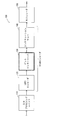
- FIG. 1 is a block diagram showing the configuration of a transmitter including a general BICM encoder.
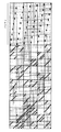
- FIG. 7 shows a parity check matrix of the RA QC LDPC code of FIG. 3 after row permutation.
- (A) It is a figure which shows the write-in process of the bit of the code word of 16K code (LDPC code whose LDPC code word length is 16200 bits) performed by 12 column-row interleavers, (b) is column-row. The figure which shows the read-out process of the bit of the code word written in (a) performed by the interleaver.
- (A) It is a figure which shows the write-in process of the bit of the code word of 16K code performed by 8 column-row interleavers, (b) is the code written by (a) performed by column-row interleaver
- FIG. 6 illustrates a potential problem for a 16K code in an 8 column DVB-T 2 bit interleaver.
- FIG. 6 illustrates a potential problem for a 16K code in a 12-sequence DVB-T 2 bit interleaver.
- FIG. 7 illustrates a potential problem when applying column twist processing to a 16K code in an 8-row DVB-T 2 bit interleaver.
- FIG. 7 illustrates a potential problem when applying column twist processing to a 16K code in a 12-column DVB-T 2 bit interleaver.
- (A) is a figure explaining the 1st condition which enables provision of the highly efficient interleaver which was found as a result of inventor's earnest research
- (b) demonstrates the 2nd condition Figure.
- FIG. 5 is a diagram showing a function of mapping by an interleaver according to an embodiment of the present invention. The block diagram which shows the structure of the interleaver which concerns on one Embodiment of this invention.
- FIG. 20 is a block diagram which shows the example of 1 structure of the section permutation unit which implements the section permutation of FIG. 20, (b) is a figure which shows the function of the mapping by the section permutation unit of (a).
- (A) is a block diagram which shows the other structural example of the section permutation unit which implements the section permutation of FIG. 20, (b) shows the function of the mapping by the section permutation unit of (a).
- Figure. The block diagram which shows the structure of the interleaver which concerns on other embodiment of this invention.
- FIG. 24 is a block diagram showing a configuration example of the bit interleaver of FIG. 23; The block diagram which shows one structural example of the transmitter which concerns on other embodiment of this invention.
- FIG. 24 is a block diagram showing a configuration example of the bit interleaver of FIG. 23; The block diagram which shows one structural example of the transmitter which concerns on other embodiment of this invention.
- FIG. 7 is a block diagram illustrating an example implementation of a BICM encoder according to yet another embodiment of the present invention.
- FIG. 7 is a block diagram illustrating an example configuration of a receiver having a non-iterative BICM decoder according to still another embodiment of the present invention.
- FIG. 10 is a block diagram illustrating an example configuration of a receiver having an iterative BICM decoder according to yet another embodiment of the present invention.
- FIG. 7 is a block diagram illustrating an example implementation of an iterative BICM decoder according to yet another embodiment of the invention.
- FIG. 1 is a block diagram showing the configuration of a transmitter including a general bit-interleaved coding and modulation (BICM) encoder.
- the transmitter 100 shown in FIG. 1 comprises an input processing unit 110, a BICM encoder (including a low-density parity check (LDPC) encoder 120, a bit interleaver 130, a constellation mapper 140), and a modulator 150.
- a BICM encoder including a low-density parity check (LDPC) encoder 120, a bit interleaver 130, a constellation mapper 140
- LDPC low-density parity check
- the input processing unit 110 converts the input bit stream into multiple blocks of a predetermined length.
- the LDPC encoder 120 encodes the block into a codeword using an LDPC code and transmits the codeword to the bit interleaver 130.
- the bit interleaver 130 interleaves the LDPC code word, performs interleaving processing, and then divides it into a cell word (constellation word) sequence.
- Constellation mapper 140 maps each cell word (constellation word) to a sequence of constellations (eg, QAM).
- a general modulator 150 at the output end includes all processing blocks from the output of the BICM encoder to a Radio Frequency (RF) power amplifier.
- RF Radio Frequency
- An LDPC code is a linear error correction code which is completely defined by a parity check matrix (PCM).
- PCM is a binary sparse matrix and indicates a connection of codeword bits (also referred to as variable node) and parity check (also referred to as check node).
- the PCM columns and rows correspond to variable nodes and check nodes, respectively.
- the combination of the variable node and the check node is indicated by an element "1" in the PCM.
- the QC LDPC code has a configuration particularly suitable for hardware implementation. In fact, QC LDPC codes are used in most of today's standards.
- the PCM of the QC LDPC code has a special configuration having a plurality of cyclic matrices.
- a circulant matrix is a square matrix in which each row is in the form of one cyclic shift of elements in the row immediately before it, and one, two, or more folded diagonal columns May exist.
- the size of each circulant matrix is Q ⁇ Q.
- Q is referred to as a cyclic factor of the QC LDPC code.
- the pseudo-cyclic structure as described above allows Q check nodes to be processed in parallel, and QC LDPC codes are clearly advantageous codes for efficient hardware implementation.
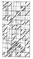
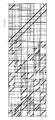
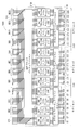
- one of the smallest squares represents one element of the PCM, and of these, the black square elements are “1”, and the other elements are “0”. It is.
- This PCM has a circulant matrix with one or two superimposed diagonal columns.
- the codeword bits are divided into blocks with Q bits.
- a block of cyclic coefficient Q bits is referred to herein as a cyclic block (or cyclic group).
- RA QC LDPC repeat-accumulate quasi-cyclic low-density parity check
- RA QC LDPC codes are known for their ease of coding and are adopted in a number of standards (eg, second generation DVB standards such as DVB-S2 standard, DVB-T2 standard, DVB-C2 standard) There is.
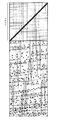
- the right side of the PCM corresponds to a parity bit, and the arrangement of the “1” element in that portion has a step structure.
- FIG. 3 exemplifies the PCM of the RA QC LDPC code whose coding rate is 2/3.
- DVB-T stands for Digital Video Broadcasting-Terrestrial
- DVB-S2 stands for Digital Video Broadcasting-Second Generation Satellite
- DVB-T2 stands for Digital Video Broadcasting-Second Generation Terrestrial
- DVB- C2 is an abbreviation of Digital Video Broadcasting-Second Generation Cable.
- the parity part of the PCM By performing appropriate permutation to change the order of bits only to the parity bits of the PCM shown in FIG. 4 subjected to the row permutation, the parity part of the PCM also has a pseudo cyclic structure.
- This technique is well known in the art, and is used under the name of parity interleaving or parity permutation in the DVB-T2 standard or the like.
- the PCM obtained as a result of applying parity permutation to the PCM shown in FIG. 4 is shown in FIG.
- LDPC codewords differ in significance from bit to bit, and constellations differ in robustness from bit to bit. Mapping the bits of the LDPC codeword directly to the constellation, ie without interleaving, does not lead to optimum performance. For this reason, the bits of the LDPC code word need to be interleaved before mapping the bits of the LDPC code word to the constellation.
- a bit interleaver 130 is provided between the LDPC encoder 120 and the constellation mapper 140. Careful design of the bit interleaver 130 improves the relevancy between bits of the LDPC codeword and bits encoded by the constellation, leading to improved reception performance. Its performance is usually measured using Bit Error Rate (BER) as a function of Signal to Noise Ratio (SNR).
- BER Bit Error Rate
- SNR Signal to Noise Ratio
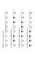
- a complex quadrature amplitude modulation (QAM) constellation consists of two independent pulse amplitude modulation (PAM) symbols, one corresponding to the real part and one to the imaginary part. It corresponds.
- the two PAM symbols each encode the same number M of bits.
- FIG. 6 which shows 8 PAM symbols using Gray codes
- the robustness levels of the bits encoded in one PAM symbol are different from each other.
- the reason why the robustness levels are different from one another is that the distance between two subsets defined by each bit (0 or 1) is different for each bit. The larger this distance, the higher the robustness level or reliability of the bit.
- the robust level of bit b3 is the highest and the robust level of bit b1 is the lowest.
- a 16 QAM constellation encodes 4 bits and has 2 robust levels.
- the 64 QAM constellation encodes 6 bits and has 3 robust levels.
- a 256 QAM constellation encodes 8 bits and has 4 robust levels.
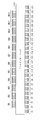
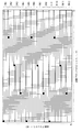
- FIG. 7 is a block diagram showing the configuration of a general interleaver corresponding to the above parameters.
- QB1, ..., QB12 are 12 cyclic blocks
- C1, ..., C24 are 24 constellation words.
- bit interleaver 710 interleaves the 96 bits of the LDPC codeword.
- DVB-T2 As a conventional bit interleaver, one of the DVB-T2 standard (ETSI EN 302 755) is known.
- the DVB-T2 standard is an improvement on the DVB-T standard which is a television standard, and describes a second generation baseline transmission system for digital terrestrial television broadcasting.
- the DVB-T2 standard details channel coding modulation systems for transmitting digital television services and general data.
- FIG. 8A is a block diagram showing the configuration of a modulator (DVB-T2 modulator) used in the DVB-T2 standard.
- the DVB-T2 modulator 800 shown in FIG. 8 (a) comprises an input processing unit 810, a BICM encoder 820, a frame builder 830 and an OFDM generator 840.
- the input processing unit 810 converts the input bit stream into blocks of a predetermined length.
- the BICM encoder 820 performs BICM processing on the input.
- the frame builder 830 generates a DVB-T2 transmission frame configuration using inputs from the BICM encoder 820 and the like.
- the OFDM generator 840 performs pilot addition, high-speed inverse Fourier transform, guard interval insertion, and the like on the transmission frame configuration of the DVB-T2 system, and outputs a transmission signal of the DVB-T2 system.
- FIG. 8B is a block diagram showing the configuration of the BICM encoder 820 of the DVB-T2 modulator shown in FIG. 8A. However, in FIG. 8B, BCH outer coding, constellation rotation, cell interleaver, time interleaver and the like are omitted.
- the BICM encoder 820 includes an LDPC encoder 821, a bit interleaver (including a parity interleaver 822 and a column-row interleaver 823), a bit-cell demultiplexer 824, and a QAM mapper 825.
- the LDPC encoder 821 encodes a block into a codeword using an LDPC code.
- the bit interleaver (parity interleaver 822 and column-row interleaver 823) performs interleaving processing to change the order of the bits of the code word.
- the bit-cell demultiplexer 824 demultiplexes the interleaved codeword bits into cell words (constellation words).
- the QAM mapper 825 maps cell words (constellation words) to complex QAM symbols.
- the complex QAM symbol is also referred to as a cell.
- the bit-cell demultiplexer 824 may be considered to be part of a bit interleaver.
- a BICM encoder based on the DVB-T2 standard can be regarded as having the standard configuration shown in FIG.
- two codewords of 16200 bits and 64800 bits are defined.
- An LDPC code having a codeword length of 16200 bits and an LDPC code having a codeword length of 64800 bits are referred to herein as a 16K code (or 16K LDPC code) and a 64K code (or 64K LDPC code).
- the number of cyclic blocks included in one code word is 45 for the 16K code and 180 for the 64K code.
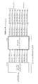
- the usable codes corresponding to these two block lengths (code word lengths) are listed in Table A.1 of ETSI EN 302 755, which is a DVB-T2 standard. 1 to Table A. 6 listed.
- the bit interleaver is used only for constellations larger than QPSK and comprises a parity interleaver 822, a column-row interleaver 823 and a bit-cell demultiplexer 824. Note that, in the definition of the DVB-T2 standard, the bit-cell demultiplexer 824 is not included in the bit interleaver. However, since the present invention relates to interleaving applied to an LDPC code before constellation mapping, the bit-cell demultiplexer 824 is also treated as part of bit interleaving.
- the parity interleaver 822 performs parity permutation to change the order of parity bits of the codeword in order to clarify the pseudo-cyclic structure of parity bits.
- the column-row interleaver 823 works conceptually by writing the bits of the LDPC codeword along the columns of the interleaver matrix and reading them along the rows. The first bit contained in the LDPC code word is written first and read first. The column-row interleaver 823 shifts the bits cyclically by a predetermined number of positions with respect to the column after writing the bits of the LDPC code word and before starting reading the bits. This is called column twisting in the DVB-T2 standard. The number of columns Nc and the number of rows Nr of the interleaver matrix corresponding to the above two LDPC codeword lengths and various constellation sizes are shown in Table 1 below.
- the number of columns Nc is twice the number of bits of one constellation, except in the case of a 16K code in a 256 QAM constellation.
- the reason for this exception is that the LDPC codeword length of 16200 is not a multiple of 16, ie twice the number of bits in the 256 QAM constellation.
- bit-cell demultiplexer 824 demultiplexes each LDPC codeword to obtain multiple parallel bit streams.
- the number of streams is twice that of the number M of bits encoded in one QAM constellation, ie 2 ⁇ M, except in the case of a 16K LDPC code in a 256 QAM constellation.
- the number of streams is M, the number of bits encoded in one QAM constellation.
- M bits encoded in one constellation are referred to as cell words (or constellation words). As described below, in a 16K LDPC code, the number of cell words obtained from one code word is 16200 / M.
- the bit-cell demultiplexer comprises a simple demultiplexer 1110 (1210, 1310) and a demultiplexing permutation unit 1120 (1220, 1320), as shown in FIG. 11 (FIGS. 12, 13).
- bit-cell demultiplexer in addition to simply demultiplexing the interleaved LDPC codeword by the simple demultiplexer 1110 (1210, 1310), by the demultiplexing unit 1120 (1220, 1220) Permutation processing is performed on the demultiplexed parallel bit stream to change its order.
- bit interleaver used in the DVB-T2 standard comes with two problems.
- the first problem is that parallelism is lost when the number of cyclic blocks in an LDPC codeword is not a multiple of the number of columns of the bit interleaver matrix. Latency increases as parallelism decreases. This is particularly a problem when iterative BICM decoding is used at the receiver. This situation occurs with some of the combinations of LDPC codeword length and constellation size for the DVB-T2 standard.
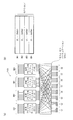
- FIGS. 14 and 15 are diagrams showing the above-mentioned situation which occurs when the number of columns of the interleaver matrix is 8 and 12, respectively, in the 16K LDPC code.
- 16 QAM and 256 QAM constellations an 8-row interleaver matrix is used.
- 64 QAM constellation a 12-column interleaver matrix is used.
- a grid represents an LDPC code word
- a small square represents one bit of the LDPC code word
- a row corresponds to a cyclic block
- a column corresponds to a bit having the same bit index as each other in a plurality of cyclic blocks.
- Filled squares represent 8 bits and 12 bits in the first row of the interleaver matrix.
- the second problem is that in the DVB-T2 standard, the number of possible bit interleaver configurations is limited by the number of columns of the bit interleaver matrix.
- FIGS. 16 and 17 show the same situation as in FIGS. 14 and 15, respectively, except that column twist processing is applied.
- the column twist value for each column used in the DVB-T 2-bit interleaver is (0, 0, 0, 1, 7, 20, 20, 21).
- the column twist value for each column used in the DVB-T 2-bit interleaver is (0, 0, 0, 2, 2, 2, 3, 3, 3, 6, 7, 7).
- Embodiment >> Hereinafter, the details of the bit interleaver (parallel bit interleaver) which satisfies the condition 1 and the condition 2 will be described. In the following, the same reference numerals are given to constituent units that perform substantially the same processing content and the same processing content.
- each of a group of M cyclic blocks or each of a group of Q constellation words is called a section (or an interleaver section).
- It is a block diagram which shows one structural example of a figure and the said bit interleaver.
- the section permutation units (2021, 2022, 2023) are independent of each other (independently of each other), and each of eight constellation words (C1 to C8, C9 to C16, C17 to C24) is 4 Section per order to change the order of a total of 32 bits of 4 cyclic blocks so that 1 bit is mapped from each of 2 cyclic blocks (QB1 to QB4, QB5 to QB8, QB9 to QB12) Perform a mutation process.
- the two conditions 1 and 2 described above are merely to ensure that the bit interleaver is divided into N / M parallel sections.
- the same permutation rule may be applied to the section permutation processing applied to these parallel sections, or different permutation rules may be applied, or only some of them may be identical to each other. Mutation rules may be applied.
- the section permutation unit maps Q bits of a cyclic block (equal in importance in the LDPC decoding process) to bits of the same bit index of Q constellation words (robust levels are equal to one another). You may do it.
- the Q bits can be arranged sequentially or in permutation order. The latter will be described using FIGS. 21 (a) and 21 (b) and the former using FIGS. 22 (a) and 22 (b).
- FIG. 21A shows an example of the configuration of the section permutation unit shown in FIG.
- Section permutation unit 2101 includes intra-cyclic block permutation units 2111-2114 and column-row permutation unit 2131. It should be noted that instead of providing four intra-cyclic block permutation units, for example, four intra-cyclic block permutations to be described later while switching processing targets in time series using one intra-cyclic block permutation unit. Processing may be performed.
- the intra-cyclic block permutation unit (2111 to 2114) performs intra-cyclic block permutation processing for changing the order of the Q (8) bits of the cyclic blocks (QB1 to QB4).
- the same permutation rule may be applied to the intra-cyclic block permutation processing applied to cyclic blocks in one section, or different permutation rules may be applied. Only part of the permutation rules may be applied to each other.
- the column-row permutation unit 2131 performs column-row permutation processing to change the order of M ⁇ Q (32) bits. Specifically, the column-row permutation unit 2131 writes M ⁇ Q (32 bits) in the row direction of a matrix of Q columns and M rows (8 columns and 4 rows), and writes M ⁇ Q pieces Column-row permutation processing equivalent to reading (32) bits in the column direction is performed. In the column-row permutation processing by the column-row permutation unit 2131, the 12th row 1350 rows in FIGS. 9A and 9B are replaced with the Q row M row, and the write processing is from the column direction to the row direction In addition, the reading process is changed from the row direction to the column direction.
- FIG. 21 (b) is a view showing the function of mapping by the section permutation unit of FIG. 21 (a).
- M 4 bits of each constellation word are indicated by b1 to b4.
- intra-cyclic block permutation processing may not be performed in the section permutation processing.
- FIG. 22 (b) Another example of the section permutation in FIG. 20, one configuration example of the section permutation unit not carrying out the intra-cyclic block permutation processing and the function of the mapping by this section permutation unit are shown in FIG. And FIG. 22 (b).
- the section permutation unit 2201 has a column-row permutation unit 2131 and performs only column-row permutation processing.
- M 4 bits of each constellation word are indicated by b1 to b4.
- section permutation described in FIGS. 21 and 22 may be performed on cyclic blocks QB5 to QB8 and QB9 to QB12.
- the bit interleaver additionally performs cyclic block permutation processing to rearrange the order of N cyclic blocks before performing section permutation processing.
- One configuration example of a bit interleaver that additionally performs cyclic block permutation processing is shown in FIG.
- the cyclic block permutation here plays the same role as the permutation by the bit-cell demultiplexer in the DVB-T2 standard.
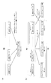
- the bit interleaver 2300 shown in FIG. 23 includes a cyclic block permutation unit 2310 and a bit permutation unit 2010 (including section permutation units 2021 to 2023).
- the cyclic block permutation unit 2310 performs cyclic block permutation processing 2311 to 2318 for changing the order of the cyclic blocks QB1 to QB12. Note that permutation rules used in cyclic block permutation processing 2311 to 2318 are the same as one another.
- Cyclic block permutation applied to N cyclic blocks is particularly useful because it enables optimal mapping of bits of an LDPC codeword to bits of a constellation, leading to optimization of reception performance. is there.
- FIG. 24 is a block diagram showing one configuration example of the bit interleaver of FIG.
- the bit interleaver 2400 of FIG. 24 performs the following three permutation processes of stages A, B and C.
- Stage A cyclic block (inter) permutation
- Stage B intra-cyclic block permutation
- Stage C column-row permutation
- the cyclic block (inter) permutation is N cycles constituting a codeword Permutation to change the order of blocks
- in-block permutation is permutation to change the order of Q bits that make up a cyclic block
- column-row permutation forms sections It is a permutation that changes the order of M ⁇ Q bits to be processed.
- the bit interleaver 2400 shown in FIG. 24 includes a cyclic block permutation unit 2310 and a bit permutation unit 2010 (section permutation units 2101 to 2103).
- the section permutation unit 2101 (2102, 2103) includes intra-cyclic block permutation units 2111 to 2114 (2115 to 2118, 2119 to 2122) and column-row permutation units 2131 (2132, 2133).
- the bit interleaver 2400 performs cyclic block (interleave) permutation by the cyclic block permutation unit 2310 (stage A), and performs intra cyclic block permutation by the intra cyclic block permutation units 2111 to 2122 (stage B) Column-row permutation is performed by column-row permutation units 2131 to 2133) (stage C).
- the intra-cyclic block permutation units 2111 to 2122 may be removed from the bit interleaver shown in FIG. 24 so that the intra-cyclic block permutation is not performed. Also, the bit interleaver may perform intra-cyclic block permutations before cyclic block (inter) block permutations instead of performing after cyclic block (inter-block) permutations; Between) may be performed before and after the permutation.
- the plurality of intra-cyclic block permutation units may have the same configuration. Therefore, a plurality of intra-cyclic block permutation units can be implemented by the same functional resource (such as a hardware block). Also, the plurality of intra-cyclic block permutations may consist of cyclic shift processing, in which case efficient hardware implementation using a barrel shifter is possible. It is also possible to implement using the barrel shifter used for the LDPC decoder.
- FIG. 25 is a block diagram showing an exemplary configuration of a transmitter according to still another embodiment of the present invention.
- the transmitter 2500 shown in FIG. 25 includes a BICM encoder (including an LDPC encoder 2510, a bit interleaver 2520, and a constellation mapper 2530) and a modulator 2540.
- the LDPC encoder 2510 encodes the input block into a codeword using a QC-LDPC code, and outputs the codeword to the bit interleaver 2520.
- bit interleaver 2520 additionally performs cyclic block permutation processing described, for example, in FIGS. 23 to 24 or as a modification thereof in addition to bit permutation processing as bit interleaving processing. May be
- Constellation mapper 2530 receives a constellation word from bit interleaver 2520 and performs constellation mapping processing on the received constellation word.
- the modulator 2740 performs orthogonal frequency division multiplexing (OFDM) modulation or the like to generate a transmission signal.
- OFDM orthogonal frequency division multiplexing
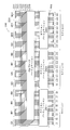
- FIG. 26 is a block diagram showing an implementation example of a BICM encoder according to still another embodiment of the present invention.
- the BICM encoder 2600 shown in FIG. 26 includes a main memory 2601, an LDPC controller 2611, a rotator 2612, a check node processor group 2613, a derotator 2614, a QB counter 2631, a table 2632, an interleaver 2633, a register group 2634, an interleaver 2635, and a mapper.
- a group 2651 is provided.
- the main memory 2601 receives a bit string to be transmitted, for example, from an input processing unit (not shown), and holds the received bit string.
- the LDPC controller 2611 outputs a read address to the main memory 2601, whereby the main memory 2601 outputs eight bits from the beginning of the bit string to the rotator 2612.
- the rotator 2612 cyclically shifts the predetermined number of 8 bits supplied from the main memory 2601 under the control of the LDPC controller 2611, and shifts the eight bits after cyclic shift to each check node processor of the check node processor group 2613. Output bit by bit.
- Each check node processor of each check node processor group 2613 performs check node processing on the input 1 bit under the control of the LDPC controller 2611, and outputs the 1 bit processing result to the derotator 2614.
- Derotator 2614 cyclically shifts the eight bits received from check node processor group 2613 a predetermined number so as to cancel the cyclic shift by rotator 2612 under the control of LDPC controller 2611, and sends the eight bits after cyclic shift to main memory 2601. Output.
- the LDPC controller 2611 outputs a write address to the main memory 2601, whereby the main memory 2601 holds 8 bits supplied from the derotator 2614.
- the LDPC controller 2611, the rotator 2612, the check node processor group 2613, and the derotator 2614 constitute an LDPC encoder 2510 of the BICM encoder in FIG.
- the QB counter 2631 counts from 0 to 11, and outputs the counter value to the table 2632.
- the read address is output.
- the main memory 2601 outputs, to the interleaver 2633, bits for one cyclic block corresponding to the counter value of the QB counter 2631.
- the cyclic block permutation (stage A) is realized by the processing of this table 2632.
- the interleaver 2633 cyclically shifts the bits for one cyclic block supplied from the main memory 2601 by a predetermined number and outputs the result to the first stage register of the register group 2634.
- intra-cyclic block permutation stage B is realized by the processing of the interleaver 2633.
- each register of the register group 2634 holds the bits for one cyclic block at the timing when the control pulse is received, and continues to output the held bits for one cyclic block until the control pulse is next received.
- the bits (32 bits) for 4 cyclic blocks are input to the interleaver 2635.
- M 4 bits
- the QB counter 2631, the table 2632, the interleaver 2633, the register group 2634, and the interleaver 2635 constitute a bit interleaver 2520 of the BICM encoder in FIG.
- mapper group 2651 maps the 4 bits supplied from the interleaver 2635 into a constellation, and outputs the mapping result.
- mapper group 2651 constitutes constellation mapper 2530 of the BICM encoder in FIG.
- the above series of processing is performed three times for one code word, in total, from the counter values “0” to “3”, “4” to “7”, and “8” to “11” of the QB counter 2631.
- FIG. 26 includes Q mappers operating in parallel
- Q mappers operating in parallel
- the parallelism can be easily increased by increasing the number of parallel interleaver sections in the bit interleaver, ie N / M.
- parallelization can be maximized by parallelizing Q ⁇ N / M mappers.
- Bit interleavers have the advantage that such parallelism can be realized without any obstacles.
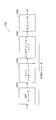
- FIG. 27 is a block diagram showing an example configuration of a receiver having a non-iterative BICM decoder according to still another embodiment of the present invention. The receiver operates in reverse to the transmitter.
- the receiver 2700 shown in FIG. 27 comprises a modulator 2710 and a non-iterative BICM decoder (including constellation demapper 2720 and bit deinterleaver 2730, LDPC decoder 2740).
- the demodulator 2710 performs demodulation processing using OFDM or the like, and outputs the demodulation processing result.
- Constellation demapper 2720 of the non-repetitive BICM decoder demaps the input from modulator 2710 to generate a so-called soft bit string, and outputs the generated soft bit string to constellation demapper 2730.
- Each soft bit is a measure of the probability that each bit will be 0 or 1.
- soft bits are represented by log likelihood ratios (LLRs) and defined as follows.
- the bit deinterleaver 2730 interleaves the soft bit sequence output from the constellation demapper 2720 by the bit interleaver in the transmitter of FIG. (Bit de-interleaving processing) is performed.
- the LDPC decoder 2740 receives the soft bit sequence subjected to bit deinterleaving from the bit deinterleaver 2730, and performs an LDPC decoding process using the received soft bit sequence.
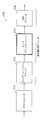
- FIG. 28 is a block diagram showing an example of configuration of a receiver having an iterative BICM decoder according to still another embodiment of the present invention. The receiver operates in reverse to the transmitter.
- the receiver 2800 shown in FIG. 28 includes a modulator 2710 and an iterative BICM decoder (constellation demapper 2720, bit deinterleaver 2730, LDPC decoder 2740, subtraction unit 2760, bit interleaver 2750).
- BICM decoder castellation demapper 2720, bit deinterleaver 2730, LDPC decoder 2740, subtraction unit 2760, bit interleaver 2750.
- the receiver 2800 in FIG. 28 performs constellation demapping processing by the constellation demapper 2720, bit deinterleaving processing by the bit deinterleaving 2730, and LDPC decoding processing by the LDPC decoder 2740.
- a subtraction unit 2760 subtracts the input of the LDPC decoder 2740 from the output of the LDPC decoder 2740, and extrinsic information obtained as a result of the subtraction is bit interleaver Output to 2750.
- the bit interleaver 2750 performs interleaving on the external information in the same interleaving rule as the bit interleaving performed on the bit sequence by the bit interleaver in the transmitter of FIG. Then, bit interleaver 2750 feeds back the interleaved external information to constellation demapper 2720. Constellation demapper 2720 uses the fed-back external information as a-priori information to calculate a more reliable LLR value.
- bit deinterleaver 2730 cancels the bit interleaving processing applied to the bit string by the bit interleaver in the transmitter of FIG. 25 to the newly calculated LLR value and restores the original order (bit deinterleaver Interleave processing).
- the LDPC decoder 2740 performs an LDPC decoding process using the LLR value subjected to the bit deinterleaving process.
- the iterative decoding loop consists of four elements: constellation demapper 2720, bit deinterleaver 2730, LDPC decoder 2740, and bit interleaver 2750.
- the bit deinterleaver 2730 and the bit interleaver 2750 have very low latency, ideally zero, and a simple configuration allows efficient implementation of the receiver.
- the above-described bit deinterleaver 2730 and bit interleaver 2750 satisfy both conditions.
- FIG. 1 One implementation of the iterative BICM decoder that implements a very efficient parallel implementation is described using FIG.
- FIG. 29 is a block diagram showing an implementation example of a BICM decoder according to still another embodiment of the present invention.
- the BICM decoder 2900 shown in FIG. 29 includes a main LLR memory 2901, a buffer LLR memory 2902, an LDPC controller 2911, a rotator 2912, a check node processor group 2913, a derotator 2914, a QB counter 2931, a table 2932, a subtraction unit 2933, an interleaver 2934, A register group 2935, an interleaver 2936, a demapper group 2937, a deinterleaver 2938, a register group 2939, a deinterleaver 2940, and a delay unit 2941 are provided.
- demapper of the demapper group 2937 performs demapping processing using the output of the demodulator (not shown), and outputs the LLR value obtained thereby to the deinterleaver 2938.
- demapper group 2937 constitutes constellation demapper 2720 of the iterative BICM decoder in FIG.
- the deinterleaver 2938 performs deinterleaving processing (interleaving processing to cancel interleaving by the stage C by the transmitter) on the LLR value, and outputs the LLR value after deinterleaving to each register of the register group 2939.
- LLR values (eight LLR values) for one circulating block are stored in each of the registers.
- the LLR values for one cyclic block held in the registers are sequentially output to the subsequent stage, and the held contents of the respective registers are sequentially updated.
- the deinterleaver 2940 performs interleaving processing (interleaving processing to cancel interleaving by the stage B by the transmitter) on the LLR values (eight LLR values) for one cyclic block to be supplied, and stores the contents of the table 2932 ( The main LLR memory 2901 and the buffer LLR memory 2902 are written according to the following description). Note that, by writing to the main LLR memory 2901 and the buffer LLR memory 2902 in accordance with the contents held in the table 2932, interleaving processing to cancel interleaving by the stage A by the transmitter is realized.
- the main LLR memory 2901 stores the LLR value after the de-interleaving process, and is also used by the LDPC decoder (LDPC controller 2911, rotator 2912, check node processor group 2913, derotator 2914).
- the LDPC decoding process is an iterative process consisting of one or more iterations. At each iteration of the LDPC decoding process, the LLR values in the main LLR memory 2901 are updated. The old LLR values are held in the buffer LLR memory 2902 to calculate the extrinsic information needed for the iterative BICM decoding process.
- the LDPC controller 2911 outputs the read address to the main LLR memory 2901 according to the parity check matrix of the LDPC code, whereby the main LLR memory 2901 sequentially outputs LLR values to the rotator 2912 for each one of the cyclic blocks.
- the rotator 2912 cyclically shifts the LLR values for one cyclic block sequentially supplied from the main LLR memory 2901 by a predetermined number under the control of the LDPC controller 2911, and the LLR values after cyclic shift are of the check node processor group 2913. Output one by one to each check node processor.
- Each check node processor of each check node processor group 2913 performs check node processing on a series of LLR values sequentially input under control of the LDPC controller 2911.
- each check node processor of the check node processor group 2913 receives control of the LDPC controller 2911 and sequentially outputs a series of LLR values as a result of check node processing.
- the derotator 2914 cyclically shifts the processing result for one cyclic block sequentially received from the check node processor group 2913 by a predetermined number so as to cancel the cyclic shift by the rotator 2912 under the control of the LDPC controller 2911 and cyclic shift
- the processing results are sequentially output to the main LLR memory 2901.
- the LDPC controller 2911 outputs a write address to the main LLR memory 2901 according to the parity check matrix of the LDPC code, whereby the main LLR memory 2901 holds the processing result for one cyclic block sequentially supplied from the derotator 2914. .
- the LDPC controller 2911 repeatedly executes the above processing in accordance with the parity check matrix of the LDPC code.
- BICM iterations are performed.
- LDPC and BICM iterative processes are also referred to as internal and external iterative processes, respectively.
- the BICM and LDPC decoding processes are well known in the art and will not be described in detail.
- the QB counter 2931 counts from 0 to 11, and outputs the counter value to the table 2932.
- the main LLR memory 2901 is supplied so that LLR values for one cyclic block corresponding to the counter value supplied from the QB counter 2931 are supplied from the main LLR memory 2901 and the buffer LLR memory 2902 to the subtraction unit group 2933. And outputs the read address to the buffer LLR memory 2902.
- main LLR memory 2901 and buffer LLR memory 2902 each output LLR values for one cyclic block corresponding to the counter value of QB counter 2931 to subtraction unit 2934.
- the delay position by the delay unit 2941 is set so that the reading position of the LLR value from the main LLR memory 2901 and the buffer LLR memory 2902 and the writing position of the LLR value to the main LLR memory 2901 and the buffer LLR memory 2902 coincide with each other. Adjustments will be made. Note that the permutation corresponding to the cyclic block permutation (stage A) is realized by the processing of the table 2932.
- Each subtraction unit 2933 of the subtraction unit group subtracts the output of the buffer LLR memory 2902 from the output of the main LLR memory 2901 and obtains external information (eight external information) for one cyclic block obtained as a result of subtraction. Output to interleaver 2934.
- the interleaver 2934 cyclically shifts the external information for one cyclic block supplied from the subtraction unit 2933 by a predetermined number and outputs the information to the first stage register of the register group 2935.
- the processing corresponding to the intra-cyclic block permutation (stage B) is realized by the processing of the interleaver 2934.
- each register of the register group 2935 receives a control pulse and holds 8 bits, and keeps holding the held 8 bits until the next control pulse is received.
- the interleaver 2936 receives external information (32 external information) for 4 cyclic blocks. .
- M 4 for each demapper of the demapper group 2937
- the QB counter 2931, the table 2932, the interleaver 2934, the register group 2935, and the interleaver 2936 constitute a bit interleaver 2750 of the BICM decoder in FIG.
- Each demapper of the demapper group 2937 performs demapping processing using the four pieces of external information supplied from the interleaver 2936 as prior information, and outputs a new LLR value to the deinterleaver 2938.
- the deinterleaver 2938 performs deinterleaving processing (interleaving processing to cancel interleaving by the stage C by the transmitter) on the LLR value, and outputs the LLR value after deinterleaving to each register of the register group 2939.
- LLR values (eight LLR values) for one circulating block are stored in each of the registers.
- the LLR values for one cyclic block held in the registers are sequentially output to the subsequent stage, and the held contents of the respective registers are sequentially updated.
- the deinterleaver 2940 performs deinterleaving processing (interleaving processing to cancel interleaving by the stage B by the transmitter) on the LLR values (eight LLR values) for one cyclic block to be supplied, and the main LLR memory 2901 and Output to buffer LLR memory 2902.
- the main LLR memory 2901 and the buffer LLR memory 2902 receive the write address from the table 2932 via the delay unit 2941, and according to the received write address, the LLR values for one cyclic block received from the deinterleaver 2940 (eight Hold LLR value).
- the write processing according to the table 2932 realizes interleaving processing (de-interleaving processing) that cancels interleaving by the stage A by the transmitter.
- the above series of processing is performed three times for one code word, in total, from the counter values “0” to “3”, “4” to “7”, and “8” to “11” of the QB counter 2931.
- the QB counter 2931, the table 2932, the deinterleaver 2938, the register group 2939, and the deinterleaver 2940 constitute a bit deinterleaver 2730 of the BICM decoder in FIG. 28.
- Interleaver 2934 and de-interleaver 2940 are reconfigurable and have a constant hardware cost, but the cost can be minimized by careful design.
- Interleaver 2936 and de-interleaver 2938 implement column-row permutation, which is constant for a given constellation size. Therefore, the implementation cost is small.
- FIG. 29 includes Q demappers operating in parallel
- the parallelism can be easily increased by increasing the number of parallel interleaver sections in the bit interleaver, ie N / M.
- parallelization can be maximized by parallelizing Q ⁇ N / M demappers.
- the bit interleaver described above has the advantage that such parallelism can be realized without any obstacles.
- a specific modulation scheme such as QPSK or QAM
- DVB is used as the constellation.
- modulation schemes such as circular constellation and multidimensional constellation used in S2 standard can be used.
- the method or apparatus described in the above embodiment may be realized by software or hardware, and is not limited to a specific form.
- the above embodiments have computer executable instructions on a computer readable medium such that a computer, microprocessor, microcontroller etc. can perform all the steps of the method and apparatus described in the above embodiments. It may be implemented in the form embodied in FIG. Also, the above embodiments may be implemented in the form of an application-specific integrated circuit (ASIC) or a field programmable gate array (FPGA).
- ASIC application-specific integrated circuit
- FPGA field programmable gate array
- a first bit interleaving method is a bit interleaving method in a communication system using a pseudo-cyclic low density parity check code, and the bit interleaving method includes N pieces of Q bits each.
- the code word of the pseudo cyclic low density parity check code which is composed of cyclic blocks, and a bit permutation process of changing the arrangement order of the bits of the code word with respect to the bits of the code word
- a plurality of constellations each comprising a bit permutation step and the codeword subjected to the bit permutation processing, each consisting of M bits, each indicating any one of 2 M predetermined constellation points And c) dividing into bits.
- the codeword before being subjected to permutation processing is divided into N / M sections, each of the sections consists of M of the cyclic blocks, and each of the constellation words is of the N / M of the sections.
- the bit permutation step is a total of one bit of each of the M different cyclic blocks in the section to which each of the constellation words is associated.
- the bit permutation process is performed such that it consists of M bits, and all the bits of each of the sections are mapped only to the Q constellation words associated with the section.
- a first bit interleaver which is an aspect of the present invention, is a bit interleaver used in a communication system using a pseudo-cyclic low density parity check code, and each of the bit interleavers comprises Q bits.
- the code word subjected to the bit permutation process is divided into a plurality of constellation words each comprising M bits and each indicating any one of 2 M predetermined constellation points.
- a bit permutation unit for outputting Of the codeword is divided into N / M sections, each of the sections consists of M cyclic blocks, and each of the constellation words is associated with one of the N / M sections.
- the bit permutation unit includes a total of M bits each consisting of one bit of each of M different cyclic blocks in the section associated with each of the constellation words. The bit permutation process is performed such that all bits of a section are mapped only to Q constellation words associated with the section.
- a second bit interleaving method is the first bit interleaving method, wherein the bit permutation step comprises N / M the sections independently of each other for the bits of each of the sections. And a section permutation step for performing section permutation processing to change the order of bits in the section.
- the second bit interleaver is the first bit interleaver, wherein the bit permutation unit performs N / M pieces of the sections independently of each other for the bits of each of the sections. And a section permutation unit that performs section permutation processing to change the order of bits in the section.
- a third bit interleaving method is the second bit interleaving method, wherein the section permutation step is performed in the section in which Q bits of the cyclic block correspond to the cyclic block.
- the section permutation process is performed so as to be mapped to bits having the same bit index of the Q constellation words that are associated.
- a third bit interleaver is the second bit interleaver, wherein the section permutation unit is configured to: Q bits of the cyclic block correspond to the section corresponding to the cyclic block The section permutation process is performed so as to be mapped to bits having the same bit index of the Q constellation words that are associated.
- the bits having the same importance of the code word are mapped to the same bits of the robust level of the constellation word, and a match between the importance and the robustness level can be obtained.
- the most significant bits of the code word may be mapped to the most robust bits of the constellation word, in which case there is a high confidence for the bits of high importance of the code word upon reception. Degree and high reception performance can be obtained.
- a fourth bit interleaving method is the second bit interleaving method, wherein the section permutation step comprises M ⁇ Q bits for M ⁇ Q bits of the section. And a column-row permutation step for performing column-row permutation processing to change the order of
- a fifth bit interleaving method which is an aspect of the present invention is the second bit interleaving method, wherein the section permutation step makes the cyclic block independent of each other for each of the N / M sections.
- the intra-cyclic block permutation step of performing intra-cyclic block permutation processing for changing the order of bits of the cyclic block to bits of each cyclic block, and the section subjected to the cyclic block permutation processing A column-row permutation step of performing column-row permutation processing for changing the order of the M ⁇ Q bits with respect to the M ⁇ Q bits of H.
- a sixth bit interleaving method which is an aspect of the present invention is the fourth bit interleaving method, wherein the column-row permutation process performs M ⁇ Q bits in a row direction of a matrix of Q columns and M rows. This process is equivalent to writing and reading M ⁇ Q bits in the column direction.
- a fourth bit interleaver is the second bit interleaver, wherein the section permutation section performs the M ⁇ Q bits on M ⁇ Q bits of the section. Apply column-row permutation processing to change the order of
- the fifth bit interleaver is the second bit interleaver, wherein the section permutation section independently performs the cyclic block on each of N / M sections.
- Per-block intra-permutation processing for changing the order of bits of the corresponding cyclic block is performed on the bits of the respective cyclic blocks, and M ⁇ Q bits of the section subjected to the cyclic block permutation processing Then, column-row permutation processing is performed to change the order of the M ⁇ Q bits.
- section permutation can be performed very efficiently.
- a seventh bit interleaving method which is an aspect of the present invention is, in the first bit interleaving method, cyclic block permutation processing for changing the arrangement order of cyclic blocks of the codeword with respect to the cyclic block of the codeword. It further has a cyclic block permutation step to be applied.
- a sixth bit interleaver which is an aspect of the present invention is a first bit interleaver that performs cyclic block permutation processing for changing the arrangement order of cyclic blocks of the codeword with respect to the cyclic block of the codeword. It further comprises a cyclic block permutation unit.
- a first bit deinterleaving method is a bit deinterleaving method for bit deinterleaving bit streams in a communication system using a pseudo-cyclic low density parity check code, which comprises N ⁇ Q bits.
- the reverse bit permutation process is a process of restoring the arrangement order changed in the bit permutation process in the first bit interleaving method.
- a first bit deinterleaver which is an aspect of the present invention, is a bit deinterleaver that bit deinterleaves a bit stream in a communication system using a pseudo-cyclic low density parity check code, and comprises N ⁇ Q bits.
- Reverse bit permutation processing for changing the order of bits of the received bit string to the received bit string in order to receive the bit string and restoring the codeword of the pseudo cyclic low density parity check code
- a bit permutation unit is provided, and the reverse bit permutation process is a process of restoring the arrangement order changed in the bit permutation process performed by the first bit interleaver.
- a first decoder which is an aspect of the present invention, is a decoder for a bit-interleaved coded modulation system using a pseudo-cyclic low density parity check code, and the probability that the corresponding bit is 0 or 1 And a first bit deinterleaver for bit de-interleaving the soft bit sequence, and a low density parity check decoder for decoding the soft bit sequence interleaved in bits.
- a second decoder is a first decoder that subtracts the input of the low density parity check decoder from the output of the low density parity check decoder, and the subtraction result of the subtractor And D. a first bit interleaver for feedback to the constellation demapper.
- the present invention can be applied to a bit interleaver in a bit interleaved coded modulation system using a pseudo-cyclic low density parity code and a bit deinterleaver corresponding to the bit interleaver.
Landscapes
- Engineering & Computer Science (AREA)
- Physics & Mathematics (AREA)
- Probability & Statistics with Applications (AREA)
- Theoretical Computer Science (AREA)
- Mathematical Physics (AREA)
- Computer Networks & Wireless Communication (AREA)
- Signal Processing (AREA)
- Multimedia (AREA)
- Error Detection And Correction (AREA)
- Detection And Prevention Of Errors In Transmission (AREA)
- Digital Transmission Methods That Use Modulated Carrier Waves (AREA)
Abstract
Description
図1は、一般的なビットインターリーブ符号化変調(bit-interleaved coding and modulation:BICM)エンコーダを含むトランスミッタの構成を示すブロック図である。図1に示すトランスミッタ100は、入力プロセシングユニット110、BICMエンコーダ(低密度パリティチェック(low-density parity check:LDPC)エンコーダ120、ビットインターリーバ130、コンステレーションマッパ140を含む)、およびモジュレータ150を備える。
1つのLDPC符号語の巡回ブロック数:N=12
1つのコンステレーションのビット数:M=4、即ち16QAM
上記パラメータでは、1つのLDPC符号語がマッピングされるコンステレーション数はQ×N/M=24である。通常、パラメータQおよびNの選択は、システムがサポートする全てのコンステレーションについて、Q×NがMの倍数となるように行われなければならない。

16QAMの場合、4050セル
64QAMの場合、2700セル
256QAMの場合、2025セル
上記の表1によると、QPSKより大きなコンステレーションについては、並列ストリームの数はカラム‐ロウインターリーバの列数に等しい。16K LDPC符号について、16QAMコンステレーション、64QAMコンステレーション、256QAMコンステレーションに対応するビット‐セルデマルチプレクサを、それぞれ、図11、図12、図13に示す。なお、ビットの表記はDVB-T2規格で用いられているものである。
発明者は、鋭意研究を行った結果、以下の2つの条件が満たされるとき、非常に効率的なインターリーバが提供できるという知見を得た。
各コンステレーション語のM個のビットが、LDPC符号語のM個の異なる巡回ブロックにマッピングされる。これは、LDPC符号語のM個の異なる巡回ブロックから1ビットずつコンステレーション語にマッピングする、ことと等価である。この概要を図18(a)に示す。
M個の巡回ブロックにマッピングされるすべてのコンステレーション語が、当該M個の巡回ブロックのみにマッピングされる。これは、QビットからなるM個の異なる巡回ブロックのM×Q個のビットの全ては、Q個のコンステレーション語にのみマッピングされる、ことと等価である。この概要を図18(b)に示す。
以下、上記の条件1、条件2を満たすビットインターリーバ(並列ビットインターリーバ)の詳細について説明する。なお、以下において、実質的に同じ処理内容、および、同じ処理内容を行う構成ユニットには同じ符号を付す。
ステージB:巡回ブロック内パーミュテーション
ステージC:カラム‐ロウパーミュテーション
ここで、巡回ブロック(間)パーミュテーションは符号語を構成するN個の巡回ブロックの並び順を換えるパーミュテーションであり、巡回ブロック内パーミュテーションは巡回ブロックを構成するQ個のビットの並び順を換えるパーミュテーションであり、カラム‐ロウパーミュテーションは、セクションを構成するM×Q個のビットの並び順を換えるパーミュテーションである。
p(b=0)はビットbが0である確率を示し、p(b=1)はビットbが1である確率を示す。ただし、p(b=0)+p(b=1)=1が成り立つ。
本発明は上記の実施の形態で説明した内容に限定されず、本発明の目的とそれに関連又は付随する目的を達成するためのいかなる形態においても実施可能であり、例えば、以下であってもよい。
本発明に係るビットインターリーブ方法、ビットインターリーバ、ビットデインターリーブ方法、ビットデインターリーバ、およびデコーダとその効果について説明する。
2010 ビットパーミュテーションユニット
2021~2023 セクションパーミュテーションユニット
2101、2201 ビットパーミュテーションユニット
2111~2122 巡回ブロック内パーミュテーションユニット
2131~2133 カラム‐ロウパーミュテーションユニット
2310 巡回ブロックパーミュテーションユニット
2500 トランスミッタ
2510 LDPCエンコーダ
2520 ビットインターリーバ
2530 コンステレーションマッパ
2700、2800 レシーバ
2710 コンステレーションデマッパ
2720 ビットデインターリーバ
2730 LDPCデコーダ
2740 減算ユニット
2750 ビットインターリーバ
Claims (17)
- 疑似巡回低密度パリティチェック符号を用いる通信システムにおけるビットインターリーブ方法であって、
前記ビットインターリーブ方法は、
それぞれがQ個のビットからなるN個の巡回ブロックで構成される前記疑似巡回低密度パリティチェック符号の符号語を受信する受信ステップと、
前記符号語のビットに対して当該符号語のビットの並び順を換えるビットパーミュテーション処理を施すビットパーミュテーションステップと、
前記ビットパーミュテーション処理が施された符号語を、それぞれM個のビットよりなり、それぞれが2M個の所定のコンステレーションポイントのいずれか1つを示す複数のコンステレーション語に分割する分割ステップと、
を有し、
前記ビットパーミュテーション処理が施される前の前記符号語はN/M個のセクションに分割され、各前記セクションはM個の前記巡回ブロックからなり、各前記コンステレーション語はN/M個の前記セクションのうちのいずれか1つと関連付けられており、
前記ビットパーミュテーションステップは、各前記コンステレーション語が、関連付けられている前記セクション中のM個の異なる前記巡回ブロックのそれぞれの1個のビットからなる計M個のビットから構成され、各前記セクションのすべてのビットが当該セクションに関連付けられているQ個の前記コンステレーション語にのみにマッピングされるように、前記ビットパーミュテーション処理を行う
ことを特徴とするビットインターリーブ方法。 - 前記ビットパーミュテーションステップは、
N/M個の前記セクションを互いに独立に、各前記セクションのビットに対して当該セクションのビットの並び順を換えるセクションパーミュテーション処理を施すセクションパーミュテーションステップ
を有することを特徴とする請求項1に記載のビットインターリーブ方法。 - 前記セクションパーミュテーションステップは、前記巡回ブロックのQ個のビットが、当該巡回ブロックに対応する前記セクションに関連付けられているQ個の前記コンステレーション語の同一のビットインデックスを有するビットにマッピングされるように、前記セクションパーミュテーション処理を行う
ことを特徴とする請求項2に記載のビットインターリーブ方法。 - 前記セクションパーミュテーションステップは、
前記セクションのM×Q個のビットに対して当該M×Q個のビットの並び順を換えるカラム‐ロウパーミュテーション処理を施すカラム‐ロウパーミュテーションステップ
を有することを特徴とする請求項2に記載のビットインターリーブ方法。 - 前記セクションパーミュテーションステップは、
N/M個の前記セクションのそれぞれについて、
前記巡回ブロックを互いに独立に、各前記巡回ブロックのビットに対して当該巡回ブロックのビットの並び順を換える巡回ブロック内パーミュテーション処理を施す巡回ブロック内パーミュテーションステップと、
前記巡回ブロックパーミュテーション処理が施された前記セクションのM×Q個のビットに対して当該M×Q個のビットの並び順を換えるカラム‐ロウパーミュテーション処理を施すカラム‐ロウパーミュテーションステップと、
有することを特徴とする請求項2に記載のビットインターリーブ方法。 - 前記カラム‐ロウパーミュテーション処理は、M×Q個のビットをQ列M行の行列の行方向に書き込み、列方向にM×Q個のビットを読み出すことと等価な処理である
ことを特徴とする請求項4に記載のビットインターリーブ方法。 - 前記符号語の巡回ブロックに対して当該符号語の巡回ブロックの並び順を換える巡回ブロックパーミュテーション処理を施す巡回ブロックパーミュテーションステップ
をさらに有することを特徴とする請求項1に記載のビットインターリーブ方法。 - 疑似巡回低密度パリティチェック符号を用いる通信システムにおいてビットストリームをビットデインターリーブするビットデインターリーブ方法であって、
N×Q個のビットからなるビット列を受信する受信ステップと、
前記疑似巡回低密度パリティチェック符号の符号語を復元するために、受信した前記ビット列のビットに対して当該ビット列のビットの並び順を換える逆ビットパーミュテーション処理を施す逆ビットパーミュテーションステップと、
を有し、
前記逆ビットパーミュテーション処理は、請求項1に記載のビットインターリーブ方法における前記ビットパーミュテーション処理で換えられた並び順を元に戻す処理である
ことを特徴とするビットデインターリーブ方法。 - 疑似巡回低密度パリティチェック符号を用いる通信システムに用いられるビットインターリーバであって、
前記ビットインターリーバは、
それぞれがQ個のビットからなるN個の巡回ブロックで構成される前記疑似巡回低密度パリティチェック符号の符号語を受信し、前記符号語のビットに対して当該符号語のビットの並び順を換えるビットパーミュテーション処理を施し、前記ビットパーミュテーション処理が施された符号語を、それぞれM個のビットよりなり、それぞれが2M個の所定のコンステレーションポイントのいずれか1つを示す複数のコンステレーション語に分割されるように出力するビットパーミュテーション部
を備え、
前記ビットパーミュテーション処理が施される前の前記符号語はN/M個のセクションに分割され、各前記セクションはM個の前記巡回ブロックからなり、各前記コンステレーション語は前記N/M個のセクションのうちの一つと関連付けられており、
前記ビットパーミュテーション部は、各前記コンステレーション語が、関連付けられている前記セクション中のM個の異なる巡回ブロックのそれぞれの1個のビットからなる計M個のビットから構成され、各前記セクションのすべてのビットが当該セクションに関連付けられているQ個のコンステレーション語にのみにマッピングされるように、前記ビットパーミュテーション処理を行う
ことを特徴とするビットインターリーバ。 - 前記ビットパーミュテーション部は、
N/M個の前記セクションを互いに独立に、各前記セクションのビットに対して当該セクションのビットの並び順を換えるセクションパーミュテーション処理を施すセクションパーミュテーション部
を有することを特徴とする請求項9に記載のビットインターリーバ。 - 前記セクションパーミュテーション部は、前記巡回ブロックのQ個のビットが、当該巡回ブロックに対応する前記セクションに関連付けられているQ個の前記コンステレーション語の同一のビットインデックスを有するビットにマッピングされるように、前記セクションパーミュテーション処理を行う
ことを特徴とする請求項10に記載のビットインターリーバ。 - 前記セクションパーミュテーション部は、
前記セクションのM×Q個のビットに対して当該M×Q個のビットの並び順を換えるカラム‐ロウパーミュテーション処理を施す
ことを特徴とする請求項10に記載のビットインターリーバ。 - 前記セクションパーミュテーション部は、
N/M個の前記セクションのそれぞれについて、
前記巡回ブロックを互いに独立に、各前記巡回ブロックのビットに対して当該巡回ブロックのビットの並び順を換える巡回ブロック内パーミュテーション処理を施し、
前記巡回ブロックパーミュテーション処理が施された前記セクションのM×Q個のビットに対して当該M×Q個のビットの並び順を換えるカラム‐ロウパーミュテーション処理を施す
ことを特徴とする請求項10に記載のビットインターリーバ。 - 前記符号語の巡回ブロックに対して当該符号語の巡回ブロックの並び順を換える巡回ブロックパーミュテーション処理を施す巡回ブロックパーミュテーション部
をさらに備えることを特徴とする請求項9に記載のビットインターリーバ。 - 疑似巡回低密度パリティチェック符号を用いる通信システムにおいてビットストリームをビットデインターリーブするビットデインターリーバであって、
N×Q個のビットからなるビット列を受信し、前記疑似巡回低密度パリティチェック符号の符号語を復元するために、受信した前記ビット列のビットに対して当該ビット列のビットの並び順を換える逆ビットパーミュテーション処理を施す逆ビットパーミュテーション部を備え、
前記逆ビットパーミュテーション処理は、請求項9に記載のビットインターリーバによって実施される前記ビットパーミュテーション処理で換えられた並び順を元に戻す処理である
ことを特徴とするビットデインターリーバ。 - 疑似巡回低密度パリティチェック符号を用いるビットインターリーブ符号化変調システム用のデコーダであって、
対応するビットが0であるか1であるかの確率を示すソフトビット列を生成するコンステレーションデマッパと、
前記ソフトビット列をビットデインターリーブする請求項15に記載のビットデインターリーバと、
ビットデインターリーブされた前記ソフトビット列をデコードする低密度パリティチェックデコーダと、
を備えることを特徴とするデコーダ。 - 前記低密度パリティチェックデコーダの出力から前記低密度パリティチェックデコーダの入力を減算する減算部と、
前記減算部の減算結果を前記コンステレーションデマッパにフィードバックする請求項9に記載のビットインターリーバと、
をさらに備えることを特徴とする請求項16に記載のデコーダ。
Priority Applications (16)
| Application Number | Priority Date | Filing Date | Title |
|---|---|---|---|
| EP12786306.6A EP2566057A4 (en) | 2011-05-18 | 2012-05-18 | PARALLEL BIT INTERLEAVER |
| EP15175491.8A EP2950453B1 (en) | 2011-05-18 | 2012-05-18 | Bit interleaver for a bicm system with qc-ldpc codes |
| EP19167664.2A EP3525353B1 (en) | 2011-05-18 | 2012-05-18 | Bit interleaver for a bicm system with qc-ldpc codes |
| US14/116,608 US9032260B2 (en) | 2011-05-18 | 2012-05-18 | Parallel bit interleaver |
| CN201280022666.6A CN103534953B (zh) | 2011-05-18 | 2012-05-18 | 比特交织方法、比特交织器、译码方法及译码器 |
| JP2013515006A JP5719927B2 (ja) | 2011-05-18 | 2012-05-18 | 並列ビットインターリーバ |
| PL15175491T PL2950453T3 (pl) | 2011-05-18 | 2012-05-18 | Moduł przeplotu bitowego dla systemu BICM z kodami QC-LDPC |
| US14/681,442 US9160372B2 (en) | 2011-05-18 | 2015-04-08 | Parallel bit interleaver by applying a cyclic block and a bit permutation process |
| US14/843,031 US9369153B2 (en) | 2011-05-18 | 2015-09-02 | Parallel bit interleaver |
| US15/156,698 US9564929B2 (en) | 2011-05-18 | 2016-05-17 | Parallel bit interleaver |
| US15/388,192 US9800270B2 (en) | 2011-05-18 | 2016-12-22 | Parallel bit interleaver |
| US15/711,202 US10097212B2 (en) | 2011-05-18 | 2017-09-21 | Parallel bit interleaver |
| US16/122,466 US10312942B2 (en) | 2011-05-18 | 2018-09-05 | Parallel bit interleaver |
| US16/385,218 US10931313B2 (en) | 2011-05-18 | 2019-04-16 | Parallel bit interleaver |
| US17/144,275 US11329672B2 (en) | 2011-05-18 | 2021-01-08 | Parallel bit interleaver |
| US17/717,333 US20220239317A1 (en) | 2011-05-18 | 2022-04-11 | Parallel bit interleaver |
Applications Claiming Priority (2)
| Application Number | Priority Date | Filing Date | Title |
|---|---|---|---|
| EP11004126.6 | 2011-05-18 | ||
| EP11004126A EP2525497A1 (en) | 2011-05-18 | 2011-05-18 | Bit-interleaved coding and modulation (BICM) with quasi-cyclic LDPC codes |
Related Child Applications (2)
| Application Number | Title | Priority Date | Filing Date |
|---|---|---|---|
| US14/116,608 A-371-Of-International US9032260B2 (en) | 2011-05-18 | 2012-05-18 | Parallel bit interleaver |
| US14/681,442 Continuation US9160372B2 (en) | 2011-05-18 | 2015-04-08 | Parallel bit interleaver by applying a cyclic block and a bit permutation process |
Publications (1)
| Publication Number | Publication Date |
|---|---|
| WO2012157282A1 true WO2012157282A1 (ja) | 2012-11-22 |
Family
ID=44773215
Family Applications (1)
| Application Number | Title | Priority Date | Filing Date |
|---|---|---|---|
| PCT/JP2012/003260 Ceased WO2012157282A1 (ja) | 2011-05-18 | 2012-05-18 | 並列ビットインターリーバ |
Country Status (9)
| Country | Link |
|---|---|
| US (10) | US9032260B2 (ja) |
| EP (4) | EP2525497A1 (ja) |
| JP (8) | JP5719927B2 (ja) |
| CN (3) | CN103534953B (ja) |
| ES (1) | ES2745550T3 (ja) |
| HU (1) | HUE045561T2 (ja) |
| PL (1) | PL2950453T3 (ja) |
| TW (1) | TWI558108B (ja) |
| WO (1) | WO2012157282A1 (ja) |
Cited By (3)
| Publication number | Priority date | Publication date | Assignee | Title |
|---|---|---|---|---|
| WO2016124256A1 (de) | 2015-02-02 | 2016-08-11 | Padaluma Ink-Jet-Solutions Gmbh & Co. Kg | Single-pass-tintenstrahldrucker |
| JP2018050325A (ja) * | 2012-07-27 | 2018-03-29 | サン パテント トラスト | 送信方法、送信機、受信方法、及び受信機 |
| JP2022043250A (ja) * | 2014-02-25 | 2022-03-15 | エレクトロニクス アンド テレコミュニケーションズ リサーチ インスチチュート | レイヤードディビジョンマルチプレキシングを利用した信号マルチプレキシング装置および信号マルチプレキシング方法 |
Families Citing this family (35)
| Publication number | Priority date | Publication date | Assignee | Title |
|---|---|---|---|---|
| US5064040A (en) | 1991-02-14 | 1991-11-12 | Deere & Company | Splined clutch drum mounting |
| US9240808B2 (en) * | 2010-09-10 | 2016-01-19 | Trellis Phase Communications, Lp | Methods, apparatus, and systems for coding with constrained interleaving |
| US9362955B2 (en) * | 2010-09-10 | 2016-06-07 | Trellis Phase Communications, Lp | Encoding and decoding using constrained interleaving |
| EP2525496A1 (en) | 2011-05-18 | 2012-11-21 | Panasonic Corporation | Bit-interleaved coding and modulation (BICM) with quasi-cyclic LDPC codes |
| EP2525497A1 (en) * | 2011-05-18 | 2012-11-21 | Panasonic Corporation | Bit-interleaved coding and modulation (BICM) with quasi-cyclic LDPC codes |
| EP2525498A1 (en) | 2011-05-18 | 2012-11-21 | Panasonic Corporation | Bit-interleaved coding and modulation (BICM) with quasi-cyclic LDPC codes |
| EP2525495A1 (en) * | 2011-05-18 | 2012-11-21 | Panasonic Corporation | Bit-interleaved coding and modulation (BICM) with quasi-cyclic LDPC codes |
| EP2552043A1 (en) * | 2011-07-25 | 2013-01-30 | Panasonic Corporation | Spatial multiplexing for bit-interleaved coding and modulation with quasi-cyclic LDPC codes |
| US9735809B2 (en) * | 2013-09-26 | 2017-08-15 | Samsung Electronics Co., Ltd. | Transmitting apparatus and signal processing method thereof |
| US11791839B2 (en) * | 2013-10-04 | 2023-10-17 | Samsung Electronics Co., Ltd. | Transmitting apparatus and signal processing method thereof |
| US9577679B2 (en) * | 2013-10-04 | 2017-02-21 | Samsung Electronics Co., Ltd. | Transmitting apparatus and signal processing method thereof |
| KR101765022B1 (ko) * | 2013-11-13 | 2017-08-03 | 엘지전자 주식회사 | 방송 신호 송신 장치, 방송 신호 수신 장치, 방송 신호 송신 방법 및 방송 신호 수신 방법 |
| EP2879318A1 (en) | 2013-11-29 | 2015-06-03 | Panasonic Corporation | Efficient component interleaving for rotated constellations with time-frequency slicing |
| WO2015079665A1 (ja) | 2013-11-29 | 2015-06-04 | パナソニック株式会社 | 送信方法、送信機、受信方法、及び受信機 |
| KR101800409B1 (ko) * | 2014-02-19 | 2017-11-23 | 삼성전자주식회사 | 송신 장치 및 그의 인터리빙 방법 |
| US10425110B2 (en) | 2014-02-19 | 2019-09-24 | Samsung Electronics Co., Ltd. | Transmitting apparatus and interleaving method thereof |
| US9602135B2 (en) * | 2014-02-20 | 2017-03-21 | Electronics And Telecommunications Research Institute | Bit interleaver for low-density parity check codeword having length of 64800 and code rate of 5/15 and 64-symbol mapping, and bit interleaving method using same |
| EP3985879A1 (en) * | 2014-02-20 | 2022-04-20 | Shanghai National Engineering Research Center of Digital Television Co., Ltd. | Multi-stage interleaving for ldpc codes |
| GB2527604A (en) * | 2014-06-27 | 2015-12-30 | Ibm | Data encoding in solid-state storage devices |
| US9369151B2 (en) * | 2014-09-25 | 2016-06-14 | Ali Misfer ALKATHAMI | Apparatus and method for resource allocation |
| KR102240728B1 (ko) * | 2015-01-27 | 2021-04-16 | 한국전자통신연구원 | 길이가 64800이며, 부호율이 4/15인 ldpc 부호어 및 64-심볼 맵핑을 위한 비트 인터리버 및 이를 이용한 비트 인터리빙 방법 |
| KR102287614B1 (ko) * | 2015-02-12 | 2021-08-10 | 한국전자통신연구원 | 길이가 64800이며, 부호율이 2/15인 ldpc 부호어 및 16-심볼 맵핑을 위한 비트 인터리버 및 이를 이용한 비트 인터리빙 방법 |
| KR102287630B1 (ko) * | 2015-02-17 | 2021-08-10 | 한국전자통신연구원 | 길이가 16200이며, 부호율이 3/15인 ldpc 부호어 및 16-심볼 맵핑을 위한 비트 인터리버 및 이를 이용한 비트 인터리빙 방법 |
| US9590758B2 (en) | 2015-05-19 | 2017-03-07 | Samsung Electronics Co., Ltd. | Transmitting apparatus and mapping method thereof |
| US9602232B2 (en) | 2015-05-19 | 2017-03-21 | Samsung Electronics Co., Ltd. | Transmitting apparatus and mapping method thereof |
| KR102397896B1 (ko) * | 2015-05-29 | 2022-05-13 | 삼성전자주식회사 | 수신 장치 및 그의 신호 처리 방법 |
| US10484017B2 (en) * | 2015-06-01 | 2019-11-19 | Sony Corporation | Data processing apparatus, and data processing method |
| US20170185328A1 (en) * | 2015-12-29 | 2017-06-29 | Alibaba Group Holding Limited | Nand flash storage error mitigation systems and methods |
| JP6920307B2 (ja) * | 2015-12-31 | 2021-08-18 | アイディーエーシー ホールディングス インコーポレイテッド | 波形ベースのデータインテグリティチェックおよびエラー訂正 |
| CN110603796B (zh) * | 2017-06-19 | 2022-07-08 | 松下电器(美国)知识产权公司 | 发送装置、接收装置、发送方法及接收方法 |
| CN115801191B (zh) | 2017-06-26 | 2024-09-13 | 中兴通讯股份有限公司 | 准循环低密度奇偶校验编码设计方法及装置 |
| CN109474373B (zh) * | 2017-09-08 | 2021-01-29 | 华为技术有限公司 | 交织方法和交织装置 |
| EP3878102B1 (en) | 2018-11-07 | 2024-03-06 | Telefonaktiebolaget LM Ericsson (publ) | Optimized implementation of (de-)interleaving for 3gpp new radio |
| DE102019200256B4 (de) | 2019-01-10 | 2020-07-30 | Fraunhofer-Gesellschaft zur Förderung der angewandten Forschung e.V. | Verschachteler |
| US10871910B1 (en) * | 2019-09-27 | 2020-12-22 | Western Digital Technologies, Inc. | Non-volatile memory with selective interleaved coding based on block reliability |
Citations (2)
| Publication number | Priority date | Publication date | Assignee | Title |
|---|---|---|---|---|
| JP2008125085A (ja) * | 2007-11-13 | 2008-05-29 | Matsushita Electric Ind Co Ltd | 変調器及び変調方法 |
| WO2009116204A1 (ja) * | 2008-03-18 | 2009-09-24 | ソニー株式会社 | データ処理装置、及びデータ処理方法 |
Family Cites Families (60)
| Publication number | Priority date | Publication date | Assignee | Title |
|---|---|---|---|---|
| US6751269B1 (en) * | 1999-01-11 | 2004-06-15 | Texas Instruments Incorporated | Bit-interleaved coded modulation for CATV upstream channels |
| US6954885B2 (en) * | 2001-12-14 | 2005-10-11 | Qualcomm Incorporated | Method and apparatus for coding bits of data in parallel |
| DE60312923T2 (de) * | 2002-05-31 | 2007-12-13 | Broadcom Corp., Irvine | Soft-In Soft-Out Dekoder für Turbo-Trelliskodierte Modulation |
| CN1228974C (zh) * | 2003-01-09 | 2005-11-23 | 北京泰美世纪科技有限公司 | 数字多媒体广播系统中的信号通讯的传送系统和方法 |
| EP1463255A1 (en) | 2003-03-25 | 2004-09-29 | Sony United Kingdom Limited | Interleaver for mapping symbols on the carriers of an OFDM system |
| GB2454195A (en) * | 2007-10-30 | 2009-05-06 | Sony Corp | Address generation polynomial and permutation matrix for DVB-T2 16k OFDM sub-carrier mode interleaver |
| CA2470546C (en) * | 2003-06-13 | 2010-08-17 | The Directv Group, Inc. | Method and apparatus for providing carrier synchronization in digital broadcast and interactive systems |
| KR100809619B1 (ko) * | 2003-08-26 | 2008-03-05 | 삼성전자주식회사 | 이동 통신 시스템에서 블록 저밀도 패러티 검사 부호부호화/복호 장치 및 방법 |
| JP4534128B2 (ja) * | 2004-03-05 | 2010-09-01 | ソニー株式会社 | 符号化方法および装置 |
| JP4607489B2 (ja) * | 2004-04-21 | 2011-01-05 | 株式会社エヌ・ティ・ティ・ドコモ | データ処理装置およびデータ処理方法 |
| EP1800408A1 (en) * | 2004-10-01 | 2007-06-27 | Thomson Licensing | A low density parity check (ldpc) decoder |
| US7760880B2 (en) * | 2004-10-13 | 2010-07-20 | Viasat, Inc. | Decoder architecture system and method |
| KR20060097503A (ko) * | 2005-03-11 | 2006-09-14 | 삼성전자주식회사 | 저밀도 패리티 검사 부호를 사용하는 통신 시스템에서 채널인터리빙/디인터리빙 장치 및 그 제어 방법 |
| KR100946884B1 (ko) * | 2005-07-15 | 2010-03-09 | 삼성전자주식회사 | 저밀도 패리티 검사 부호를 사용하는 통신 시스템에서 채널인터리빙/디인터리빙 장치 및 그 제어 방법 |
| CN100571068C (zh) * | 2005-08-18 | 2009-12-16 | 北京泰美世纪科技有限公司 | 数字卫星广播系统及信息传输方法、纠错编码系统及方法 |
| CN100341211C (zh) | 2005-12-22 | 2007-10-03 | 天津大学 | 高功率内腔倍频激光器相位失配补偿加热器及方法 |
| CN100438394C (zh) * | 2006-01-12 | 2008-11-26 | 北京大学 | 非规则置换矩阵ldpc码的构造方法及装置 |
| KR100819247B1 (ko) * | 2006-01-13 | 2008-04-03 | 삼성전자주식회사 | 통신 시스템에서 신호 송수신 장치 및 방법 |
| CN100589564C (zh) * | 2006-04-18 | 2010-02-10 | 华为技术有限公司 | 一种手持电视系统中的信道交织方法及系统 |
| US7830957B2 (en) * | 2006-05-02 | 2010-11-09 | Qualcomm Incorporated | Parallel bit interleaver for a wireless system |
| US7752529B2 (en) * | 2006-07-26 | 2010-07-06 | Broadcom Corporation | Combined LDPC (low density parity check) encoder and syndrome checker |
| JP4856605B2 (ja) * | 2006-08-31 | 2012-01-18 | パナソニック株式会社 | 符号化方法、符号化装置、及び送信装置 |
| CN101601187B (zh) * | 2007-01-24 | 2014-08-20 | 高通股份有限公司 | 对可变大小分组进行ldpc编码和译码 |
| US8418023B2 (en) * | 2007-05-01 | 2013-04-09 | The Texas A&M University System | Low density parity check decoder for irregular LDPC codes |
| EP2056510B1 (en) * | 2007-10-30 | 2013-04-03 | Sony Corporation | Data processing apparatus and method |
| TWI459724B (zh) | 2007-11-26 | 2014-11-01 | Sony Corp | Data processing device and data processing method |
| TWI410055B (zh) | 2007-11-26 | 2013-09-21 | Sony Corp | Data processing device, data processing method and program product for performing data processing method on computer |
| NZ585421A (en) * | 2007-11-26 | 2013-03-28 | Sony Corp | An apparatus for encoding using a low-density parity check code |
| TWI497920B (zh) | 2007-11-26 | 2015-08-21 | Sony Corp | Data processing device and data processing method |
| TWI538415B (zh) | 2007-11-26 | 2016-06-11 | Sony Corp | Data processing device and data processing method |
| CN101488819B (zh) * | 2008-01-15 | 2013-02-27 | 华为技术有限公司 | 一种低密度奇偶校验码编码调制方法及装置 |
| CN101494629A (zh) * | 2008-01-24 | 2009-07-29 | 华为技术有限公司 | 获取符号映射分集、生成星座图、调制的方法和装置 |
| ES2545782T3 (es) | 2008-03-03 | 2015-09-15 | Rai Radiotelevisione Italiana S.P.A. | Patrones de permutación de bits para modulación codificada de LDPC y constelaciones QAM |
| US20090282316A1 (en) * | 2008-05-07 | 2009-11-12 | Texas Instruments Incorporated | Memory Access in Low-Density Parity Check Decoders |
| ITTO20080472A1 (it) * | 2008-06-16 | 2009-12-17 | Rai Radiotelevisione Italiana Spa | Metodo di elaborazione di segnali digitali e sistema di trasmissione e ricezione che implementa detto metodo |
| CN101345738B (zh) * | 2008-08-29 | 2011-07-27 | 成都德芯数字科技有限公司 | 一种数字电视地面广播信号的映射与交织方法及系统 |
| KR101481435B1 (ko) * | 2008-12-18 | 2015-01-12 | 삼성전자주식회사 | 저밀도 패리티 검사 부호를 사용하는 통신 시스템에서 신호매핑 방법 및 이를 위한 장치 |
| CN102349257B (zh) * | 2009-01-14 | 2015-02-25 | 汤姆森特许公司 | 设计用于多边型低密度奇偶校验编码调制的多路分用器的方法和装置 |
| US8219874B2 (en) * | 2009-02-19 | 2012-07-10 | Nec Laboratories America, Inc. | Multi-dimensional LDPC coded modulation for high-speed optical transmission systems |
| US8495450B2 (en) * | 2009-08-24 | 2013-07-23 | Samsung Electronics Co., Ltd. | System and method for structured LDPC code family with fixed code length and no puncturing |
| US8566668B1 (en) * | 2010-01-04 | 2013-10-22 | Viasat, Inc. | Edge memory architecture for LDPC decoder |
| EP2566156A4 (en) * | 2010-04-28 | 2015-04-29 | Lg Electronics Inc | BROADCAST TRANSMITTER, BROADCAST RECEIVER AND METHOD FOR SENDING AND RECEIVING BROADCAST SIGNALS WITH DEVICES FOR TRANSMITTING AND RECEIVING BROADCAST SIGNALS |
| RU2013146898A (ru) * | 2011-03-22 | 2015-04-27 | Нек Корпорейшн | Устройство кодирования с коррекцией ошибок, способ кодирования с коррекцией ошибок и программа кодирования с коррекцией ошибок |
| US8656245B2 (en) * | 2011-04-13 | 2014-02-18 | California Institute Of Technology | Method of error floor mitigation in low-density parity-check codes |
| US8739001B2 (en) * | 2011-04-23 | 2014-05-27 | Analogies Sa | LDPC encoding and decoding techniques |
| EP2525495A1 (en) * | 2011-05-18 | 2012-11-21 | Panasonic Corporation | Bit-interleaved coding and modulation (BICM) with quasi-cyclic LDPC codes |
| EP2525497A1 (en) * | 2011-05-18 | 2012-11-21 | Panasonic Corporation | Bit-interleaved coding and modulation (BICM) with quasi-cyclic LDPC codes |
| EP2525496A1 (en) | 2011-05-18 | 2012-11-21 | Panasonic Corporation | Bit-interleaved coding and modulation (BICM) with quasi-cyclic LDPC codes |
| KR101922990B1 (ko) * | 2011-11-11 | 2018-11-28 | 삼성전자주식회사 | 멀티미디어 통신 시스템에서 준순환 저밀도 패리티 검사 부호 송/수신 장치 및 방법 |
| US8930789B1 (en) * | 2013-01-23 | 2015-01-06 | Viasat, Inc. | High-speed LDPC decoder |
| BR112015027153B1 (pt) * | 2013-05-02 | 2021-12-14 | Sony Corp | Dispositivo e método de processamento de dados |
| WO2014195303A1 (en) * | 2013-06-05 | 2014-12-11 | Sony Corporation | Transmitter and transmission method for transmitting payload data and emergency information |
| KR102080607B1 (ko) * | 2013-07-08 | 2020-02-25 | 삼성전자주식회사 | 방송 및 통신 시스템에서 신호 송수신 장치 및 방법 |
| CN105453553B (zh) * | 2013-08-01 | 2018-08-28 | Lg 电子株式会社 | 发送广播信号的设备、接收广播信号的设备、发送广播信号的方法以及接收广播信号的方法 |
| US9602137B2 (en) * | 2014-02-19 | 2017-03-21 | Samsung Electronics Co., Ltd. | Transmitting apparatus and interleaving method thereof |
| EP3985879A1 (en) * | 2014-02-20 | 2022-04-20 | Shanghai National Engineering Research Center of Digital Television Co., Ltd. | Multi-stage interleaving for ldpc codes |
| BR112016021595B1 (pt) * | 2014-03-19 | 2022-09-20 | Samsung Electronics Co., Ltd | Aparelho transmissor, e método de intercalação de um aparelho transmissor |
| US10326471B2 (en) * | 2014-05-22 | 2019-06-18 | Electronics And Telecommunications Research Institute | Bit interleaver for low-density parity check codeword having length of 16200 and code rate of 3/15 and quadrature phase shift keying, and bit interleaving method using same |
| US9847794B2 (en) * | 2015-05-19 | 2017-12-19 | Samsung Electronics Co., Ltd. | Transmitting apparatus and interleaving method thereof |
| US9787326B2 (en) * | 2015-05-19 | 2017-10-10 | Samsung Electronics Co., Ltd. | Method and apparatus for encoding and decoding low density parity check codes |
-
2011
- 2011-05-18 EP EP11004126A patent/EP2525497A1/en not_active Withdrawn
-
2012
- 2012-05-18 WO PCT/JP2012/003260 patent/WO2012157282A1/ja not_active Ceased
- 2012-05-18 CN CN201280022666.6A patent/CN103534953B/zh active Active
- 2012-05-18 EP EP15175491.8A patent/EP2950453B1/en active Active
- 2012-05-18 CN CN201610890041.1A patent/CN107070462B/zh active Active
- 2012-05-18 CN CN201610889133.8A patent/CN107070461B/zh active Active
- 2012-05-18 JP JP2013515006A patent/JP5719927B2/ja active Active
- 2012-05-18 PL PL15175491T patent/PL2950453T3/pl unknown
- 2012-05-18 US US14/116,608 patent/US9032260B2/en active Active
- 2012-05-18 TW TW101117762A patent/TWI558108B/zh active
- 2012-05-18 EP EP12786306.6A patent/EP2566057A4/en not_active Ceased
- 2012-05-18 ES ES15175491T patent/ES2745550T3/es active Active
- 2012-05-18 EP EP19167664.2A patent/EP3525353B1/en active Active
- 2012-05-18 HU HUE15175491A patent/HUE045561T2/hu unknown
-
2015
- 2015-03-19 JP JP2015056276A patent/JP5852758B2/ja active Active
- 2015-04-08 US US14/681,442 patent/US9160372B2/en active Active
- 2015-09-02 US US14/843,031 patent/US9369153B2/en active Active
- 2015-12-04 JP JP2015237159A patent/JP6010209B2/ja active Active
-
2016
- 2016-05-17 US US15/156,698 patent/US9564929B2/en active Active
- 2016-09-14 JP JP2016179349A patent/JP6208307B2/ja active Active
- 2016-12-22 US US15/388,192 patent/US9800270B2/en active Active
-
2017
- 2017-09-04 JP JP2017169316A patent/JP6386640B2/ja active Active
- 2017-09-21 US US15/711,202 patent/US10097212B2/en active Active
-
2018
- 2018-08-03 JP JP2018146400A patent/JP6559306B2/ja active Active
- 2018-09-05 US US16/122,466 patent/US10312942B2/en active Active
-
2019
- 2019-04-16 US US16/385,218 patent/US10931313B2/en active Active
- 2019-07-12 JP JP2019129855A patent/JP6772345B2/ja active Active
-
2020
- 2020-09-30 JP JP2020164382A patent/JP7011013B2/ja active Active
-
2021
- 2021-01-08 US US17/144,275 patent/US11329672B2/en active Active
-
2022
- 2022-04-11 US US17/717,333 patent/US20220239317A1/en not_active Abandoned
Patent Citations (2)
| Publication number | Priority date | Publication date | Assignee | Title |
|---|---|---|---|---|
| JP2008125085A (ja) * | 2007-11-13 | 2008-05-29 | Matsushita Electric Ind Co Ltd | 変調器及び変調方法 |
| WO2009116204A1 (ja) * | 2008-03-18 | 2009-09-24 | ソニー株式会社 | データ処理装置、及びデータ処理方法 |
Non-Patent Citations (2)
| Title |
|---|
| DOUILLARD, C.: "The Bit Interleaved Coded Modulation module for DVB-NGH: Enhanced features for mobile reception", TELECOMMUNICATIONS (ICT), 2012 19TH INTERNATIONAL CONFERENCE, 23 April 2012 (2012-04-23) * |
| See also references of EP2566057A4 * |
Cited By (7)
| Publication number | Priority date | Publication date | Assignee | Title |
|---|---|---|---|---|
| JP2018050325A (ja) * | 2012-07-27 | 2018-03-29 | サン パテント トラスト | 送信方法、送信機、受信方法、及び受信機 |
| JP2022043250A (ja) * | 2014-02-25 | 2022-03-15 | エレクトロニクス アンド テレコミュニケーションズ リサーチ インスチチュート | レイヤードディビジョンマルチプレキシングを利用した信号マルチプレキシング装置および信号マルチプレキシング方法 |
| JP7221373B2 (ja) | 2014-02-25 | 2023-02-13 | エレクトロニクス アンド テレコミュニケーションズ リサーチ インスチチュート | レイヤードディビジョンマルチプレキシングを利用した信号マルチプレキシング装置および信号マルチプレキシング方法 |
| US11943090B2 (en) | 2014-02-25 | 2024-03-26 | Electronics And Telecommunications Research Institute | Signal multiplexing device and signal multiplexing method using layered division multiplexing |
| US12362982B2 (en) | 2014-02-25 | 2025-07-15 | Electronics And Telecommunications Research Institute | Signal multiplexing device and signal multiplexing method using layered division multiplexing |
| WO2016124256A1 (de) | 2015-02-02 | 2016-08-11 | Padaluma Ink-Jet-Solutions Gmbh & Co. Kg | Single-pass-tintenstrahldrucker |
| US10252531B2 (en) | 2015-02-02 | 2019-04-09 | Padaluma Ink-Jet-Solutions Gmbh & Co. Kg | Single pass inkjet printer |
Also Published As
Similar Documents
| Publication | Publication Date | Title |
|---|---|---|
| JP7011013B2 (ja) | 並列ビットインターリーバ | |
| JP7011014B2 (ja) | 並列ビットインターリーバ | |
| JP6567154B2 (ja) | 並列ビットインターリーバ | |
| CN103563256B (zh) | 比特交织方法、比特交织器、解码方法以及解码器 |
Legal Events
| Date | Code | Title | Description |
|---|---|---|---|
| WWE | Wipo information: entry into national phase |
Ref document number: 2012786306 Country of ref document: EP |
|
| 121 | Ep: the epo has been informed by wipo that ep was designated in this application |
Ref document number: 12786306 Country of ref document: EP Kind code of ref document: A1 |
|
| ENP | Entry into the national phase |
Ref document number: 2013515006 Country of ref document: JP Kind code of ref document: A |
|
| WWE | Wipo information: entry into national phase |
Ref document number: 14116608 Country of ref document: US |
|
| NENP | Non-entry into the national phase |
Ref country code: DE |