WO2012157321A1 - シート - Google Patents
シート Download PDFInfo
- Publication number
- WO2012157321A1 WO2012157321A1 PCT/JP2012/055556 JP2012055556W WO2012157321A1 WO 2012157321 A1 WO2012157321 A1 WO 2012157321A1 JP 2012055556 W JP2012055556 W JP 2012055556W WO 2012157321 A1 WO2012157321 A1 WO 2012157321A1
- Authority
- WO
- WIPO (PCT)
- Prior art keywords
- angle
- reclining
- seat back
- folding
- control
- Prior art date
- Legal status (The legal status is an assumption and is not a legal conclusion. Google has not performed a legal analysis and makes no representation as to the accuracy of the status listed.)
- Ceased
Links
Images


Classifications
-
- B—PERFORMING OPERATIONS; TRANSPORTING
- B60—VEHICLES IN GENERAL
- B60N—SEATS SPECIALLY ADAPTED FOR VEHICLES; VEHICLE PASSENGER ACCOMMODATION NOT OTHERWISE PROVIDED FOR
- B60N2/00—Seats specially adapted for vehicles; Arrangement or mounting of seats in vehicles
- B60N2/02—Seats specially adapted for vehicles; Arrangement or mounting of seats in vehicles the seat or part thereof being movable, e.g. adjustable
- B60N2/22—Seats specially adapted for vehicles; Arrangement or mounting of seats in vehicles the seat or part thereof being movable, e.g. adjustable the back-rest being adjustable
- B60N2/2222—Seats specially adapted for vehicles; Arrangement or mounting of seats in vehicles the seat or part thereof being movable, e.g. adjustable the back-rest being adjustable the back-rest having two or more parts
-
- B—PERFORMING OPERATIONS; TRANSPORTING
- B60—VEHICLES IN GENERAL
- B60N—SEATS SPECIALLY ADAPTED FOR VEHICLES; VEHICLE PASSENGER ACCOMMODATION NOT OTHERWISE PROVIDED FOR
- B60N2/00—Seats specially adapted for vehicles; Arrangement or mounting of seats in vehicles
- B60N2/02—Seats specially adapted for vehicles; Arrangement or mounting of seats in vehicles the seat or part thereof being movable, e.g. adjustable
- B60N2/0224—Non-manual adjustments, e.g. with electrical operation
- B60N2/02246—Electric motors therefor
-
- B—PERFORMING OPERATIONS; TRANSPORTING
- B60—VEHICLES IN GENERAL
- B60N—SEATS SPECIALLY ADAPTED FOR VEHICLES; VEHICLE PASSENGER ACCOMMODATION NOT OTHERWISE PROVIDED FOR
- B60N2/00—Seats specially adapted for vehicles; Arrangement or mounting of seats in vehicles
- B60N2/02—Seats specially adapted for vehicles; Arrangement or mounting of seats in vehicles the seat or part thereof being movable, e.g. adjustable
- B60N2/0224—Non-manual adjustments, e.g. with electrical operation
- B60N2/0244—Non-manual adjustments, e.g. with electrical operation with logic circuits
- B60N2/0272—Non-manual adjustments, e.g. with electrical operation with logic circuits using sensors or detectors for detecting the position of seat parts
-
- B—PERFORMING OPERATIONS; TRANSPORTING
- B60—VEHICLES IN GENERAL
- B60N—SEATS SPECIALLY ADAPTED FOR VEHICLES; VEHICLE PASSENGER ACCOMMODATION NOT OTHERWISE PROVIDED FOR
- B60N2/00—Seats specially adapted for vehicles; Arrangement or mounting of seats in vehicles
- B60N2/02—Seats specially adapted for vehicles; Arrangement or mounting of seats in vehicles the seat or part thereof being movable, e.g. adjustable
- B60N2/0296—Central command actuator to selectively switch on or engage one of several special purpose circuits or mechanisms
-
- B—PERFORMING OPERATIONS; TRANSPORTING
- B60—VEHICLES IN GENERAL
- B60N—SEATS SPECIALLY ADAPTED FOR VEHICLES; VEHICLE PASSENGER ACCOMMODATION NOT OTHERWISE PROVIDED FOR
- B60N2/00—Seats specially adapted for vehicles; Arrangement or mounting of seats in vehicles
- B60N2/02—Seats specially adapted for vehicles; Arrangement or mounting of seats in vehicles the seat or part thereof being movable, e.g. adjustable
- B60N2/22—Seats specially adapted for vehicles; Arrangement or mounting of seats in vehicles the seat or part thereof being movable, e.g. adjustable the back-rest being adjustable
-
- B—PERFORMING OPERATIONS; TRANSPORTING
- B60—VEHICLES IN GENERAL
- B60N—SEATS SPECIALLY ADAPTED FOR VEHICLES; VEHICLE PASSENGER ACCOMMODATION NOT OTHERWISE PROVIDED FOR
- B60N2/00—Seats specially adapted for vehicles; Arrangement or mounting of seats in vehicles
- B60N2/02—Seats specially adapted for vehicles; Arrangement or mounting of seats in vehicles the seat or part thereof being movable, e.g. adjustable
- B60N2002/0204—Seats specially adapted for vehicles; Arrangement or mounting of seats in vehicles the seat or part thereof being movable, e.g. adjustable characterised by the seat or seat part turning about or moving along a non-standard, particular axis, i.e. an axis different from the axis characterising the conventional movement
- B60N2002/0216—Seats specially adapted for vehicles; Arrangement or mounting of seats in vehicles the seat or part thereof being movable, e.g. adjustable characterised by the seat or seat part turning about or moving along a non-standard, particular axis, i.e. an axis different from the axis characterising the conventional movement the seat or seat part turning about or moving along a transversal axis
-
- B—PERFORMING OPERATIONS; TRANSPORTING
- B60—VEHICLES IN GENERAL
- B60N—SEATS SPECIALLY ADAPTED FOR VEHICLES; VEHICLE PASSENGER ACCOMMODATION NOT OTHERWISE PROVIDED FOR
- B60N2205/00—General mechanical or structural details
- B60N2205/30—Seat or seat parts characterised by comprising plural parts or pieces
Definitions
- the present invention relates to a seat in which an upper portion of a seat back and a lower portion of the seat back are connected so as to be adjustable in angle.
- Patent Document 1 proposes a vehicle seat having a folded structure in which a seat back is divided into two vertically.
- a motor for reclining the lower part of the seat back and a motor for folding the upper part of the seat back are provided, and each motor is configured to tilt. There is.
- the seat back lower part and the seat back upper part are independently driven by the user's switch operation to adjust the inclination thereof, so that the seat adjustment suitable for the occupant is difficult.
- the present invention has been made to solve the above problems. And the purpose is to provide a vehicle seat that can be easily adjusted to each angle suitable for the occupant without having to independently adjust the reclining angle at the lower part of the seat back and the folding angle at the upper part of the seat back. There is to do.
- the present invention has a seat cushion and a seat back that is divided into an upper seat back portion and a lower seat back portion, and the upper seat back portion and the lower seat back portion are connected so that the angles corresponding to each can be adjusted.
- a reclining drive unit that varies a reclining angle that is an angle formed by the lower portion of the seat back with respect to the seat cushion, and a middle folding drive unit that varies an angle formed by the upper portion of the seat back with respect to the lower portion of the seat back are provided.
- the control part which performs the interlocking control which interlocks a reclining angle and a bending angle based on a predetermined interlocking function is provided.
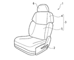
- FIG. 1 is a perspective view of a seat according to an embodiment of the present invention.
- FIG. 2 is a block diagram of a drive control device for a seat according to an embodiment of the present invention.
- FIG. 3 is a flowchart showing drive control in the seat according to the embodiment of the present invention.
- FIG. 4 is a diagram showing an operation pattern in the case where coordinates corresponding to the detected reclining angle and half-turn angle are on a straight line representing the interlock function.
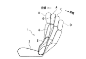
- FIG. 5 is a diagram showing a seat angle changing state when the reclining angle is changed and the folding angle is also changed following the change.
- FIG. 6 shows a seat back when the interlock control is started when the angle determined by the interlock function based on one of the reclining angle and the folding angle does not match the other angle.
- FIG. 7 shows a seat back when the interlock control is started when the angle determined by the interlock function based on one of the reclining angle and the folding angle does not coincide with the other angle. It is a figure explaining the operation
- a seat 1 As shown in the perspective view of FIG. 1, a seat 1 according to an embodiment of the present invention includes a seat cushion 2 and a seat back 3.
- the seat back 3 is divided into an upper seat back 4 and a lower seat back 5.
- the seat includes a reclining mechanism that varies the reclining angle and a middle folding mechanism that varies the middle folding angle.
- the reclining angle is an angle formed by the seat back lower part 5 with respect to the seat cushion 2.
- the folding angle is an angle formed by the seat back upper part 4 with respect to the seat back lower part 5.
- a headrest 6 is attached to the seat back upper portion 4.
- FIG. 2 shows a block diagram of a drive control device that adjusts the reclining angle and the folding angle.
- the drive control device includes a reclining mechanism, a folding mechanism, and a seat drive determination unit 13.
- the reclining mechanism includes a reclining drive unit 7, a reclining state detection unit 8, and a reclining switch 9.
- the middle folding mechanism includes a middle folding driving means 10, a middle folding state detecting means 11, and a middle folding switch 12.
- the reclining drive means 7 drives the reclining motor to change the reclining angle by tilting the seat back lower part 5 forward or backward.
- the reclining state detection means 8 includes a reclining sensor that detects a reclining angle.
- the middle folding drive means 10 drives the middle folding motor to change the middle folding angle by tilting the seat back upper part 4 forward or backward.
- the folded state detecting means 11 includes a folded sensor that detects a folded angle.
- the seat drive determination unit 13 functions as a control unit that performs interlocking control for interlocking the detected reclining angle and bending angle based on a predetermined interlocking function. As will be described in detail later, this interlocking function is a function related to the reclining angle and the bending angle.
- FIG. 3 is a flowchart showing drive control in the seat according to the embodiment of the present invention. This flowchart starts by turning on the ignition key of the engine. In the process of step S1, the reclining state detection unit 8 detects the reclining state, and the folded state detecting unit 11 detects the folded state.
- step S2 the sheet drive determination unit 13 detects whether or not the folding switch 12 is driven (pressed). When the folding switch 12 is driven (YES), the sheet drive determination unit 13 drives the folding drive means 10 in the process of step S3.
- step S4 when the folding switch 12 is not driven (NO), the seat drive determination unit 13 detects whether or not the reclining switch 9 is driven (pressed).
- step S5 when the reclining switch 9 is driven (YES), the seat drive determining unit 13 issues an instruction to the reclining state detecting unit 8 and the folded state detecting unit 11, which are in the reclining state and the folded state. Are detected respectively.
- step S6 the reclining sensor (reclining state detection means 8) detects the current rotation angle of the reclining motor (reclining drive means 7), and the seat drive determination unit 13 calculates the angle of the reclining motor. To do.
- the folding sensor the folding state detection means 11 detects the current rotation angle of the folding motor (the folding drive means 10), and the sheet drive determination unit 13 detects the angle of the folding motor.
- step S7 the driving state of the reclining motor and the folding motor is determined.
- This is represented by a straight line X in FIG.
- the interlock function in the present invention is not limited to a linear function, and can be expressed by a straight line or a curve.
- the coordinates corresponding to the reclining angle and the folding angle detected by the reclining state detection unit 8 and the folding state detection unit 11 are on the straight line X representing the above-described interlocking function. In this case, as shown in FIG.
- the reclining motor and the folding motor are driven so that the coordinates corresponding to the reclining angle and the folding angle move along the straight line X representing the interlock function.
- both motors are driven in accordance with the switch operating direction (forward tilt direction or backward tilt direction) of the reclining switch 9 while always detecting the angle.
- the seat back lower part 5 tilts forward, for example, from the A state indicated by the solid line in FIG. 5 to the B state indicated by the broken line.
- the processes of steps S8 and S9 are executed, and the seat back upper portion 4 tilts backward.
- the entire seat back operates in the opening direction.
- the reclining switch 9 is operated so that the seat back lower part 5 tilts backward, from the A state indicated by the solid line in FIG. 5 to the C state indicated by the one-dot chain line or the D state indicated by the two-dot chain line, The seat back lower part 5 tilts backward.
- the processes of steps S8 and S9 are executed, and the seat back upper portion 4 tilts forward.
- the entire seat back operates in the closing direction.
- the angle of the seat back upper part 4 and the seat back lower part 5 can be automatically adjusted by only operating the reclining switch 9 by the occupant in the process of step S4. Further, since the predetermined interlocking function shown in FIG. 4 is set to a comfortable folding angle at each reclining angle, a comfortable seat back shape can be obtained at any reclining angle.
- step S10 it is determined that the coordinates corresponding to the reclining angle and the folding angle have reached the target value when the driving control is performed so that the coordinates are on the straight line X representing the interlocking function described above.
- This flowchart is finished. If the reclining angle and the turning angle have not reached the target values, that is, if the above-described coordinates are not on the straight line X representing the interlock function, this flowchart is returned to the process of step S5.
- the detected current folding angle F is smaller than the folding angle determined by the interlock function based on the current reclining angle.
- the seat back upper portion 4 is tilted forward until the current folding angle F matches the folding angle determined by the interlock function based on the detected current reclining angle.
- drive control is performed so as to correspond to the operation indicated by the YF line in FIG. 6 in accordance with the straight line X representing the interlock function.
- the detected current folding angle H is smaller than the folding angle determined by the interlock function based on the current reclining angle.
- the seat back lower part 5 is tilted forward to a position where the current reclining angle coincides with the reclining angle determined by the interlock function based on the folding angle H.
- drive control is performed so as to correspond to the operation indicated by the YH line in FIG. 7 in accordance with the straight line X representing the interlock function.
- control up to the target angle of each of the reclining angle and the folding angle is normal feedback control based on the sensor detection value of each motor and the target angle.
- the folding angle of the seat back upper part 4 is independent of the reclining angle of the seat back lower part 5 in the process of step S ⁇ b> 2. And can be controlled. Therefore, the seat back upper part 4 can be set to a passenger's favorite folding position.
- the interlock control is performed when the second angle determined by the interlock function determined in advance based on the first angle of either the reclining angle or the folding angle does not coincide with any of the other third angles. It is assumed that it will be started. In this case, one of the reclining drive means 7 and the folding drive means 10 is operated independently, and the third angle is matched with the second angle. Next, after matching, the reclining drive means 7 and the folding drive means 10 are controlled to operate in conjunction with the interlock function. That is, the operations in steps S5 to S10 and the operations in FIGS. 6 and 7 are performed. Therefore, the reclining drive means and the middle-fold drive means can be interlocked with each other without feeling uncomfortable with respect to the occupant's reclining drive direction.
- the selection of whether the independent operation control described above is performed by operating the reclining drive means 7 or the folding drive means 10 depends on the occupant's seat operation. Determined. That is, the occupant is determined in accordance with the driving direction in which the seat back lower part 5 is inclined forward or backward. Based on this determination, the operations of steps S5 to S10 and the operations of FIGS. 6 and 7 are performed. Therefore, the reclining and the middle break can be interlocked with each other without feeling uncomfortable with respect to the driving direction of the occupant's reclining.
- the interlock function is a linear function, but the same control can be performed with a non-linear function, and an equivalent effect can be obtained.
- both the reclining driving means and the middle folding driving means are controlled and driven.
- the middle folding drive is performed. Only the means were driven independently.
- the roles of the reclining drive means and the folding drive means may be reversed, and when the folding switch is operated, both the reclining drive means and the folding drive means may be controlled and driven. Also in this case, the same effect as the above-described embodiment can be obtained.
- the control unit performs control for interlocking the reclining angle at the lower part of the seat back and the folding angle at the upper part of the seat back based on a predetermined interlocking function. Therefore, it is not necessary for the occupant to independently adjust the reclining angle and the folding angle. That is, by adjusting the angle of the control unit, a comfortable seat angle for the occupant can be easily obtained.
Landscapes
- Engineering & Computer Science (AREA)
- Aviation & Aerospace Engineering (AREA)
- Transportation (AREA)
- Mechanical Engineering (AREA)
- Seats For Vehicles (AREA)
- Chairs For Special Purposes, Such As Reclining Chairs (AREA)
- Chair Legs, Seat Parts, And Backrests (AREA)
Abstract
Description
2 シートクッション
3 シートバック
4 シートバック上部
5 シートバック下部
7 リクライニング駆動手段
8 リクライニング状態検出手段
9 リクライニングスイッチ
10 中折れ駆動手段
11 中折れ状態検出手段
12 中折れスイッチ
13 シート駆動判断部(制御部)
Claims (4)
- シートクッションと、
シートバック上部及びシートバック下部に分割され、前記シートバック上部及びシートバック下部が、それぞれに対応する角度を調整できるように連結されたシートバックと、
前記シートクッションに対する前記シートバック下部のなす角度であるリクライニング角度を可変するリクライニング駆動手段と、
前記シートバック下部に対する前記シートバック上部のなす角度である中折れ角度を可変する中折れ駆動手段と、
前記リクライニング角度と前記中折れ角度とを、予め定めた連動関数に基づいて連動させる連動制御を行う制御部と、
を備えることを特徴とするシート。 - 前記連動制御に加えて、前記制御部が、前記中折れ角度を、前記リクライニング角度とは独立して制御可能とすることを特徴とする請求項1に記載のシート。
- 前記リクライニング角度及び前記中折れ角度のいずれか一方の第一角度に基づいて前記連動関数により決定される第二角度が、前記いずれか他方の第三角度と一致しない場合において前記連動制御が開始されるとき、
前記制御部が、以下の制御を行うことを特徴とする請求項2に記載のシート。
(A1)前記第三角度が前記第二角度と一致するまでは、前記リクライニング駆動手段と前記中折れ駆動手段のいずれか一方を独立して稼働し、
(A2)前記第三角度が前記第二角度と一致した後は、前記連動関数に合わせて前記リクライニング駆動手段及び前記中折れ駆動手段を連動させる。 - 前記リクライニング角度及び前記中折れ角度のいずれか一方の第一角度に基づいて前記連動関数により決定される第二角度が、前記いずれか他方の第三角度と一致しない場合において前記連動制御が開始されるとき、
前記制御部が、前記シートバック下部を前傾又は後傾する駆動方向に応じて、前記中折れ角度と前記リクライニング角度のいずれか一方を前記連動関数と一致させた後に他方も前記連動関数と一致させる制御を行うことを特徴とする請求項3に記載のシート。
Priority Applications (4)
| Application Number | Priority Date | Filing Date | Title |
|---|---|---|---|
| JP2013515025A JP5652548B2 (ja) | 2011-05-19 | 2012-03-05 | シート |
| US14/118,326 US8983737B2 (en) | 2011-05-19 | 2012-03-05 | Seat with middle bend mechanism |
| EP12785018.8A EP2710925B1 (en) | 2011-05-19 | 2012-03-05 | Seat |
| CN201280023235.1A CN103533863B (zh) | 2011-05-19 | 2012-03-05 | 座椅 |
Applications Claiming Priority (2)
| Application Number | Priority Date | Filing Date | Title |
|---|---|---|---|
| JP2011112206 | 2011-05-19 | ||
| JP2011-112206 | 2011-05-19 |
Publications (1)
| Publication Number | Publication Date |
|---|---|
| WO2012157321A1 true WO2012157321A1 (ja) | 2012-11-22 |
Family
ID=47176663
Family Applications (1)
| Application Number | Title | Priority Date | Filing Date |
|---|---|---|---|
| PCT/JP2012/055556 Ceased WO2012157321A1 (ja) | 2011-05-19 | 2012-03-05 | シート |
Country Status (5)
| Country | Link |
|---|---|
| US (1) | US8983737B2 (ja) |
| EP (1) | EP2710925B1 (ja) |
| JP (1) | JP5652548B2 (ja) |
| CN (1) | CN103533863B (ja) |
| WO (1) | WO2012157321A1 (ja) |
Cited By (3)
| Publication number | Priority date | Publication date | Assignee | Title |
|---|---|---|---|---|
| JP2015098204A (ja) * | 2013-11-18 | 2015-05-28 | トヨタ紡織株式会社 | 乗物用シートのポジション調整装置 |
| JP2018127042A (ja) * | 2017-02-07 | 2018-08-16 | 本田技研工業株式会社 | 車両シート制御システム、車両シートの制御方法、および車両シートの制御プログラム |
| JP2020164135A (ja) * | 2019-03-29 | 2020-10-08 | 株式会社Subaru | 座席シート |
Families Citing this family (10)
| Publication number | Priority date | Publication date | Assignee | Title |
|---|---|---|---|---|
| BR112013007306B1 (pt) * | 2010-10-01 | 2020-08-04 | Nissan Motor., Ltd | Assento de veículo e método de ajsute de rigidez para o mesmo |
| US9610862B2 (en) * | 2014-10-14 | 2017-04-04 | Faurecia Automotive Seating, Llc | Seat position sensing and adjustment |
| CN104503482A (zh) * | 2014-12-09 | 2015-04-08 | 江苏工程职业技术学院 | 椅子靠背角度自动调节控制装置及调节方法 |
| USD750927S1 (en) * | 2015-03-16 | 2016-03-08 | Ford Motor Company | Vehicle seat back cushion |
| USD767292S1 (en) * | 2015-03-16 | 2016-09-27 | Ford Motor Company | Vehicle seat |
| CN104786889A (zh) * | 2015-05-01 | 2015-07-22 | 长春富维—江森自控汽车饰件系统有限公司 | 一种座靠联动的座椅骨架结构 |
| USD805312S1 (en) * | 2016-04-04 | 2017-12-19 | Dr. Ing. H.C. F. Porsche Aktiengesellschaft | Vehicle seat |
| USD804206S1 (en) * | 2016-04-04 | 2017-12-05 | Dr. Inc. h.c. F. Porsche Aktiengesellschaft | Vehicle seat |
| JP6421365B2 (ja) * | 2017-02-10 | 2018-11-14 | 本田技研工業株式会社 | 車両シート制御システム、車両シートの制御方法、およびプログラム |
| KR102282104B1 (ko) * | 2019-08-07 | 2021-07-27 | 엘지전자 주식회사 | 로봇 |
Citations (4)
| Publication number | Priority date | Publication date | Assignee | Title |
|---|---|---|---|---|
| JPH0781468A (ja) * | 1993-09-13 | 1995-03-28 | Mazda Motor Corp | 稼働シートの制御装置 |
| JPH09109747A (ja) * | 1995-10-24 | 1997-04-28 | Nissan Diesel Motor Co Ltd | 車両の座席装置 |
| JP2579110Y2 (ja) | 1992-06-30 | 1998-08-20 | 株式会社タチエス | 中折れシートバックにおける角度調整装置のストッパ構造 |
| JP2004081355A (ja) * | 2002-08-23 | 2004-03-18 | Nobutoshi Yamazaki | 車両用シート装置 |
Family Cites Families (15)
| Publication number | Priority date | Publication date | Assignee | Title |
|---|---|---|---|---|
| JPH0585234A (ja) * | 1991-05-20 | 1993-04-06 | Tachi S Co Ltd | パワーシートのモータ制御方法およびモータ制御装置 |
| JP2633789B2 (ja) * | 1993-01-13 | 1997-07-23 | 池田物産株式会社 | 座席装置 |
| JP2005087367A (ja) * | 2003-09-16 | 2005-04-07 | Mitsuba Corp | 電動式ギャッチベッドの駆動制御装置 |
| DE102004005705B4 (de) * | 2004-02-05 | 2011-06-16 | Isringhausen Gmbh & Co Kg | Rückenlehne für einen Fahrzeugsitz und Fahrzeugsitz |
| DE102004025507A1 (de) * | 2004-05-21 | 2005-12-15 | Johnson Controls Gmbh Automotive Systems Group | Fahrzeugsitz |
| JP4534624B2 (ja) * | 2004-06-24 | 2010-09-01 | 日産自動車株式会社 | 車両用シート装置および車両用シートの調整方法 |
| GB2415618B (en) * | 2004-07-01 | 2006-09-20 | Lear Corp | Hydraulically powered folding vehicle seat fold |
| US7344195B2 (en) * | 2005-02-11 | 2008-03-18 | Lear Corporation | Dampener for a vehicle seat recliner |
| EP2001702A4 (en) * | 2006-04-06 | 2011-08-17 | Intier Automotive Inc | VERTICAL SEAT |
| US8235467B2 (en) * | 2006-04-27 | 2012-08-07 | Ts Tech Co., Ltd. | Vehicle seat |
| DE102007004767A1 (de) * | 2007-01-31 | 2008-08-07 | Bayerische Motoren Werke Aktiengesellschaft | Rückenlehne für einen Fahrzeugsitz mit neigungsverstellbarem Lehnenkopf |
| JP4957416B2 (ja) * | 2007-07-05 | 2012-06-20 | アイシン精機株式会社 | 車両用シート装置 |
| JP5602410B2 (ja) * | 2008-12-18 | 2014-10-08 | アップリカ・チルドレンズプロダクツ株式会社 | 座席構造 |
| JP5654273B2 (ja) * | 2009-09-04 | 2015-01-14 | デルタ工業株式会社 | 車両用シートバックフレームの構造 |
| BR112013007306B1 (pt) * | 2010-10-01 | 2020-08-04 | Nissan Motor., Ltd | Assento de veículo e método de ajsute de rigidez para o mesmo |
-
2012
- 2012-03-05 WO PCT/JP2012/055556 patent/WO2012157321A1/ja not_active Ceased
- 2012-03-05 US US14/118,326 patent/US8983737B2/en active Active
- 2012-03-05 CN CN201280023235.1A patent/CN103533863B/zh active Active
- 2012-03-05 JP JP2013515025A patent/JP5652548B2/ja active Active
- 2012-03-05 EP EP12785018.8A patent/EP2710925B1/en active Active
Patent Citations (4)
| Publication number | Priority date | Publication date | Assignee | Title |
|---|---|---|---|---|
| JP2579110Y2 (ja) | 1992-06-30 | 1998-08-20 | 株式会社タチエス | 中折れシートバックにおける角度調整装置のストッパ構造 |
| JPH0781468A (ja) * | 1993-09-13 | 1995-03-28 | Mazda Motor Corp | 稼働シートの制御装置 |
| JPH09109747A (ja) * | 1995-10-24 | 1997-04-28 | Nissan Diesel Motor Co Ltd | 車両の座席装置 |
| JP2004081355A (ja) * | 2002-08-23 | 2004-03-18 | Nobutoshi Yamazaki | 車両用シート装置 |
Non-Patent Citations (1)
| Title |
|---|
| See also references of EP2710925A4 |
Cited By (5)
| Publication number | Priority date | Publication date | Assignee | Title |
|---|---|---|---|---|
| JP2015098204A (ja) * | 2013-11-18 | 2015-05-28 | トヨタ紡織株式会社 | 乗物用シートのポジション調整装置 |
| JP2018127042A (ja) * | 2017-02-07 | 2018-08-16 | 本田技研工業株式会社 | 車両シート制御システム、車両シートの制御方法、および車両シートの制御プログラム |
| US10391890B2 (en) | 2017-02-07 | 2019-08-27 | Honda Motor Co., Ltd. | Vehicle seat control system, vehicle seat control method, and storage medium |
| JP2020164135A (ja) * | 2019-03-29 | 2020-10-08 | 株式会社Subaru | 座席シート |
| JP7165096B2 (ja) | 2019-03-29 | 2022-11-02 | 株式会社Subaru | 座席シート |
Also Published As
| Publication number | Publication date |
|---|---|
| EP2710925B1 (en) | 2015-09-09 |
| EP2710925A1 (en) | 2014-03-26 |
| CN103533863B (zh) | 2016-03-30 |
| CN103533863A (zh) | 2014-01-22 |
| EP2710925A4 (en) | 2014-11-05 |
| JPWO2012157321A1 (ja) | 2014-07-31 |
| US20140077560A1 (en) | 2014-03-20 |
| JP5652548B2 (ja) | 2015-01-14 |
| US8983737B2 (en) | 2015-03-17 |
Similar Documents
| Publication | Publication Date | Title |
|---|---|---|
| JP5652548B2 (ja) | シート | |
| JP6582458B2 (ja) | ドライビングポジション制御装置 | |
| JP6629609B2 (ja) | 車両用アームレスト制御装置 | |
| JP2006131187A (ja) | オートドライビングポジションシステムとその制御方法 | |
| US20100094514A1 (en) | Vehicular seat operation device and vehicular seat operation method | |
| JP6411410B2 (ja) | 車両用シート制御装置 | |
| KR20190058560A (ko) | 스위치 위치의 조정 방법 및 차량용 조작 장치 | |
| CN113320448B (zh) | 一种座椅调节方法、装置及计算机可读存储介质 | |
| EP1245438B1 (en) | Controller positioning structure for vehicle | |
| JP2020082745A (ja) | パワーシート装置 | |
| CN110525278A (zh) | 车辆座椅控制器 | |
| JP6969360B2 (ja) | 車両シート制御装置 | |
| JP6089797B2 (ja) | 操作スイッチ | |
| JP2008001150A (ja) | ミラー角度調整装置 | |
| JP2012224307A (ja) | 乗員保護装置 | |
| JP2008135323A (ja) | 車両用シートの電動操作装置 | |
| JP5291573B2 (ja) | シート状態変更装置 | |
| JP5297051B2 (ja) | 車両用シート装置および車両用シート装置の制御方法 | |
| JP2012214193A (ja) | 車両用シート制御装置 | |
| KR101816685B1 (ko) | 헤드레스트 자동 높이조절장치 | |
| WO2019124503A1 (ja) | 車両シート制御装置 | |
| JP2019089401A (ja) | 車両用シートの調整方法及び車両用シート装置 | |
| JP2019077308A (ja) | 車両用シート制御装置 | |
| JP2019202696A (ja) | 乗物用シートの制御方法 | |
| JP2009298282A (ja) | シート装置 |
Legal Events
| Date | Code | Title | Description |
|---|---|---|---|
| WWE | Wipo information: entry into national phase |
Ref document number: 201280023235.1 Country of ref document: CN |
|
| 121 | Ep: the epo has been informed by wipo that ep was designated in this application |
Ref document number: 12785018 Country of ref document: EP Kind code of ref document: A1 |
|
| WWE | Wipo information: entry into national phase |
Ref document number: 2012785018 Country of ref document: EP |
|
| ENP | Entry into the national phase |
Ref document number: 2013515025 Country of ref document: JP Kind code of ref document: A |
|
| WWE | Wipo information: entry into national phase |
Ref document number: 14118326 Country of ref document: US |
|
| NENP | Non-entry into the national phase |
Ref country code: DE |