WO2012157609A1 - ストロークシミュレータ、このストロークシミュレータを有するマスタシリンダ、およびこのマスタシリンダを用いたブレーキシステム - Google Patents
ストロークシミュレータ、このストロークシミュレータを有するマスタシリンダ、およびこのマスタシリンダを用いたブレーキシステム Download PDFInfo
- Publication number
- WO2012157609A1 WO2012157609A1 PCT/JP2012/062302 JP2012062302W WO2012157609A1 WO 2012157609 A1 WO2012157609 A1 WO 2012157609A1 JP 2012062302 W JP2012062302 W JP 2012062302W WO 2012157609 A1 WO2012157609 A1 WO 2012157609A1
- Authority
- WO
- WIPO (PCT)
- Prior art keywords
- simulator
- piston
- stroke
- master cylinder
- brake
- Prior art date
- Legal status (The legal status is an assumption and is not a legal conclusion. Google has not performed a legal analysis and makes no representation as to the accuracy of the status listed.)
- Ceased
Links
Images

Classifications
-
- F—MECHANICAL ENGINEERING; LIGHTING; HEATING; WEAPONS; BLASTING
- F15—FLUID-PRESSURE ACTUATORS; HYDRAULICS OR PNEUMATICS IN GENERAL
- F15B—SYSTEMS ACTING BY MEANS OF FLUIDS IN GENERAL; FLUID-PRESSURE ACTUATORS, e.g. SERVOMOTORS; DETAILS OF FLUID-PRESSURE SYSTEMS, NOT OTHERWISE PROVIDED FOR
- F15B15/00—Fluid-actuated devices for displacing a member from one position to another; Gearing associated therewith
- F15B15/18—Combined units comprising both motor and pump
-
- B—PERFORMING OPERATIONS; TRANSPORTING
- B60—VEHICLES IN GENERAL
- B60T—VEHICLE BRAKE CONTROL SYSTEMS OR PARTS THEREOF; BRAKE CONTROL SYSTEMS OR PARTS THEREOF, IN GENERAL; ARRANGEMENT OF BRAKING ELEMENTS ON VEHICLES IN GENERAL; PORTABLE DEVICES FOR PREVENTING UNWANTED MOVEMENT OF VEHICLES; VEHICLE MODIFICATIONS TO FACILITATE COOLING OF BRAKES
- B60T7/00—Brake-action initiating means
- B60T7/02—Brake-action initiating means for personal initiation
- B60T7/04—Brake-action initiating means for personal initiation foot actuated
- B60T7/042—Brake-action initiating means for personal initiation foot actuated by electrical means, e.g. using travel or force sensors
-
- B—PERFORMING OPERATIONS; TRANSPORTING
- B60—VEHICLES IN GENERAL
- B60T—VEHICLE BRAKE CONTROL SYSTEMS OR PARTS THEREOF; BRAKE CONTROL SYSTEMS OR PARTS THEREOF, IN GENERAL; ARRANGEMENT OF BRAKING ELEMENTS ON VEHICLES IN GENERAL; PORTABLE DEVICES FOR PREVENTING UNWANTED MOVEMENT OF VEHICLES; VEHICLE MODIFICATIONS TO FACILITATE COOLING OF BRAKES
- B60T11/00—Transmitting braking action from initiating means to ultimate brake actuator without power assistance or drive or where such assistance or drive is irrelevant
- B60T11/10—Transmitting braking action from initiating means to ultimate brake actuator without power assistance or drive or where such assistance or drive is irrelevant transmitting by fluid means, e.g. hydraulic
- B60T11/16—Master control, e.g. master cylinders
- B60T11/20—Tandem, side-by-side, or other multiple master cylinder units
-
- B—PERFORMING OPERATIONS; TRANSPORTING
- B60—VEHICLES IN GENERAL
- B60T—VEHICLE BRAKE CONTROL SYSTEMS OR PARTS THEREOF; BRAKE CONTROL SYSTEMS OR PARTS THEREOF, IN GENERAL; ARRANGEMENT OF BRAKING ELEMENTS ON VEHICLES IN GENERAL; PORTABLE DEVICES FOR PREVENTING UNWANTED MOVEMENT OF VEHICLES; VEHICLE MODIFICATIONS TO FACILITATE COOLING OF BRAKES
- B60T8/00—Arrangements for adjusting wheel-braking force to meet varying vehicular or ground-surface conditions, e.g. limiting or varying distribution of braking force
- B60T8/32—Arrangements for adjusting wheel-braking force to meet varying vehicular or ground-surface conditions, e.g. limiting or varying distribution of braking force responsive to a speed condition, e.g. acceleration or deceleration
- B60T8/34—Arrangements for adjusting wheel-braking force to meet varying vehicular or ground-surface conditions, e.g. limiting or varying distribution of braking force responsive to a speed condition, e.g. acceleration or deceleration having a fluid pressure regulator responsive to a speed condition
- B60T8/40—Arrangements for adjusting wheel-braking force to meet varying vehicular or ground-surface conditions, e.g. limiting or varying distribution of braking force responsive to a speed condition, e.g. acceleration or deceleration having a fluid pressure regulator responsive to a speed condition comprising an additional fluid circuit including fluid pressurising means for modifying the pressure of the braking fluid, e.g. including wheel driven pumps for detecting a speed condition, or pumps which are controlled by means independent of the braking system
- B60T8/4072—Systems in which a driver input signal is used as a control signal for the additional fluid circuit which is normally used for braking
- B60T8/4081—Systems with stroke simulating devices for driver input
- B60T8/4086—Systems with stroke simulating devices for driver input the stroke simulating device being connected to, or integrated in the driver input device
-
- B—PERFORMING OPERATIONS; TRANSPORTING
- B60—VEHICLES IN GENERAL
- B60T—VEHICLE BRAKE CONTROL SYSTEMS OR PARTS THEREOF; BRAKE CONTROL SYSTEMS OR PARTS THEREOF, IN GENERAL; ARRANGEMENT OF BRAKING ELEMENTS ON VEHICLES IN GENERAL; PORTABLE DEVICES FOR PREVENTING UNWANTED MOVEMENT OF VEHICLES; VEHICLE MODIFICATIONS TO FACILITATE COOLING OF BRAKES
- B60T8/00—Arrangements for adjusting wheel-braking force to meet varying vehicular or ground-surface conditions, e.g. limiting or varying distribution of braking force
- B60T8/32—Arrangements for adjusting wheel-braking force to meet varying vehicular or ground-surface conditions, e.g. limiting or varying distribution of braking force responsive to a speed condition, e.g. acceleration or deceleration
- B60T8/34—Arrangements for adjusting wheel-braking force to meet varying vehicular or ground-surface conditions, e.g. limiting or varying distribution of braking force responsive to a speed condition, e.g. acceleration or deceleration having a fluid pressure regulator responsive to a speed condition
- B60T8/40—Arrangements for adjusting wheel-braking force to meet varying vehicular or ground-surface conditions, e.g. limiting or varying distribution of braking force responsive to a speed condition, e.g. acceleration or deceleration having a fluid pressure regulator responsive to a speed condition comprising an additional fluid circuit including fluid pressurising means for modifying the pressure of the braking fluid, e.g. including wheel driven pumps for detecting a speed condition, or pumps which are controlled by means independent of the braking system
- B60T8/4072—Systems in which a driver input signal is used as a control signal for the additional fluid circuit which is normally used for braking
- B60T8/4081—Systems with stroke simulating devices for driver input
- B60T8/409—Systems with stroke simulating devices for driver input characterised by details of the stroke simulating device
Definitions
- the present invention relates to a technical field of a stroke simulator that generates a reaction force according to depression of a pedal used in a brake system, a technical field of a master cylinder having the stroke simulator, and a technical field of a brake system using the master cylinder. It is about.
- the relationship between the front and rear directions is that the direction in which the input shaft moves when the brake pedal is depressed is “front”, and the direction in which the input shaft returns when the brake pedal is released is “rear”. .
- This regenerative cooperative brake system detects the depression stroke of the brake pedal, and based on the detected stroke, the control unit (Electric control unit: ECU) calculates the braking force by the regenerative brake and the braking force by the friction brake, The vehicle is braked with the calculated braking force.
- ECU Electronic control unit
- the control unit determines the braking force based on the depression stroke of the brake pedal, so that the reaction force corresponding to the depression stroke of the brake pedal is not transmitted to the driver. Therefore, in order to enable the driver to recognize a reaction force according to the depression stroke of the brake pedal, a master cylinder having a pedal feel simulator unit has been proposed (for example, see Patent Document 1).
- FIG. 4 is a diagram schematically showing a master cylinder having a pedal feel simulator portion described in Patent Document 1.
- 1 is a master cylinder
- 2 is a tandem master cylinder section for generating brake fluid pressure of a friction brake
- 3 is a pedal feel simulator section (stroke simulator) provided integrally with the tandem master cylinder section 2
- 4 is a brake
- 5 is a stroke sensor that detects the stroke of the input shaft 4
- 6 is a reservoir tank that stores brake fluid.
- the tandem master cylinder portion 2 has a primary piston 7, a secondary piston 8, a primary hydraulic chamber 9 defined by the primary piston 7 and the secondary piston 8, and a secondary defined by the secondary piston 8, as in the known tandem master cylinder.
- the hydraulic chamber 10 includes a primary spring 11 that constantly biases the primary piston 7 toward the non-operating position, and a secondary spring 12 that biases the secondary piston 8 toward the non-operating position.
- the primary hydraulic chamber 9 is connected to a brake cylinder (not shown in FIG. 4) of one brake system and communicates with the reservoir tank 6 at a non-operating position of the illustrated primary piston 7.
- the primary hydraulic chamber 9 is disconnected from the reservoir tank 6 when the primary piston 7 moves forward, and a brake hydraulic pressure is generated in the primary hydraulic chamber 9.
- the secondary hydraulic chamber 10 is connected to a brake cylinder (not shown in FIG. 4) of the other brake system, and communicates with the reservoir tank 6 at a non-operating position of the illustrated secondary piston 8.
- the secondary hydraulic pressure chamber 10 is disconnected from the reservoir tank 6 when the secondary piston 8 moves forward, and a brake hydraulic pressure is generated in the secondary hydraulic pressure chamber 10.
- the tandem master cylinder portion 2 has a power chamber 13 between the primary piston 7 and the cylinder wall.
- the power chamber 13 is supplied with hydraulic fluid from a power source (not shown) when the brake is operated.
- the hydraulic fluid is supplied so that the hydraulic pressure in the power chamber 13 becomes a hydraulic pressure corresponding to the braking force by the friction brake calculated by the control unit.
- the pedal sensation simulator unit 3 always places the simulator operating piston 14 operated by the input shaft 4, the simulator operating hydraulic pressure chamber 15 in which the simulator operating hydraulic pressure is generated by the operation of the simulator operating piston 14, and the simulator operating piston 14 at the non-operating position. And a simulator operating piston return spring 16 composed of a coil spring that is biased in the direction, and a pedal feel simulator cartridge 17. Further, the pedal feel simulator cartridge 17 includes a first reaction force simulator piston 18 (corresponding to a reaction force simulator member of the present invention) to which the simulator operation hydraulic pressure in the simulator operation hydraulic pressure chamber 15 is applied, and a first reaction force simulator piston 18.
- the first reaction force simulator spring 19 (equivalent to the reaction force simulator member of the present invention) that normally urges the first reaction force simulator spring 19 and the second reaction force simulator piston 20 that supports the first reaction force simulator spring 19 (the present invention).
- a second reaction force simulator spring 21 (corresponding to the reaction force simulator member of the present invention) that constantly urges the second reaction force simulator piston 20 toward the non-actuated position.
- the input shaft 4 moves forward (leftward in FIG. 4), so that the simulator operating piston 14 moves forward (actuates) while flexing the simulator operating piston return spring 16 elastically.
- the simulator working fluid pressure chamber 15 is shut off from the reservoir tank 6 by the operation of the simulator working piston 14, the simulator working fluid pressure is generated in the simulator working fluid pressure chamber 15.
- This simulator hydraulic pressure acts on the first reaction force simulator piston 18.
- the first reaction force simulator piston 18 moves downward in FIG. 4 while pressing the first reaction force simulator spring 19 to bend elastically.
- the second reaction force simulator piston 20 moves (activates) downward in FIG. 4 while bending the second reaction force simulator spring 21 by the pressing force of the first reaction force simulator piston 18.
- the first and second reaction force simulator springs 19 and 21 act on the first reaction force simulator piston 18 as a reaction force with a force corresponding to the amount of bending thereof.
- the first and second reaction forces are obtained.
- the movement of the simulator pistons 18 and 20 stops.
- the simulator working fluid pressure in the simulator working fluid pressure chamber 15 is a fluid pressure corresponding to the depression stroke of the brake pedal.
- the reaction force of the first reaction force simulator piston 18 is converted into the simulator operation hydraulic pressure and acts on the simulator operation piston 14, and further the reaction force is transmitted from the simulator operation piston 14 to the brake pedal via the input shaft 4. .
- the driver recognizes the reaction force corresponding to the depression stroke of the brake pedal from the brake pedal.
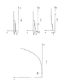
- the pedal feel characteristic diagram (that is, the characteristic diagram of the reaction force F with respect to the stroke S of the brake pedal) in the pedal feel simulator unit 3 configured as described above is a characteristic diagram shown in FIG. That is, the pedal feeling characteristic diagram shows that the reaction force F is relatively small with respect to the increase of the stroke S in the initial operation of the pedal feeling simulator unit 3, and the reaction force with respect to the increase of the stroke S when the stroke S increases by a predetermined amount.
- a characteristic curve curved so that F becomes relatively large is drawn.
- the tandem master cylinder portion 2 and the pedal feel simulator portion 3 are both in the inoperative state shown in FIG. That is, the hydraulic fluid is not supplied to the power chamber 13 from the power source, and both the primary piston 7 and the secondary piston 8 are in the non-operating position shown in FIG. Therefore, both the primary hydraulic pressure chamber 9 and the secondary hydraulic pressure chamber 10 communicate with the reservoir tank 6, and no brake hydraulic pressure is generated in the primary hydraulic pressure chamber 9 and the secondary hydraulic pressure chamber 10. Further, the simulator working fluid pressure chamber 15 communicates with the reservoir tank 6, and no simulator working fluid pressure is generated in the simulator working fluid pressure chamber 15.
- a control unit (not shown) drives and controls the power source based on the stroke of the input shaft 4 from the stroke sensor 5 (that is, the depression stroke of the brake pedal). Thereby, hydraulic fluid is supplied from the power source to the power chamber 13, and the primary piston 7 and the secondary piston 8 move forward. Then, both the primary hydraulic pressure chamber 9 and the secondary hydraulic pressure chamber 10 are disconnected from the reservoir tank 6, and brake hydraulic pressure is generated in the primary hydraulic pressure chamber 9 and the secondary hydraulic pressure chamber 10. These brake fluid pressures are respectively supplied to two corresponding brake cylinders, and the corresponding wheels of the automobile are braked.
- the control unit stops the power source. Then, both the primary piston 7 and the secondary piston 8 are stopped, and the brake fluid pressure in the primary fluid pressure chamber 9 and the secondary fluid pressure chamber 10 both becomes a fluid pressure corresponding to the depression stroke of the brake pedal. That is, the brake is applied to the wheel with a braking force corresponding to the depression stroke of the brake pedal.
- the pedal feeling simulator unit 3 transmits a reaction force corresponding to the depression stroke of the brake pedal to the brake pedal. Therefore, the driver recognizes this reaction force and senses that the brake is applied to the wheel with the braking force corresponding to the depression stroke of the brake pedal.
- the input shaft 4 strokes backward (in the non-actuated position), and the stroke of the input shaft 4 is detected by the stroke sensor 5.
- the control unit controls a control valve (not shown) based on the stroke detected by the stroke sensor 5 and discharges the hydraulic fluid in the power chamber 13 to the reservoir tank 6. Thereby, the hydraulic pressure in the power chamber 13 is lowered, and the primary piston 7 and the secondary piston 8 are moved backward by the urging force of the primary spring 11 and the secondary spring 12, respectively.
- the hydraulic pressure in the power chamber 13 becomes atmospheric pressure, the primary piston 7 and the secondary piston 8 are both in the inoperative position shown in FIG. 4 and the brakes of the wheels are released.
- the simulator operating piston 14 moves backward by the biasing force of the simulator operating piston return spring 16 as the input shaft 4 strokes backward.
- the simulator operating hydraulic pressure chamber 15 communicates with the reservoir tank 6 and the simulator operating hydraulic pressure in the simulator operating hydraulic pressure chamber 15 decreases.
- the hydraulic pressure in the simulator operating hydraulic chamber 15 is atmospheric pressure.
- the pedal sensation simulator unit 3 described in Patent Document 1 has a plurality of springs including a simulator operation piston return spring 16, a first reaction force simulator spring 19, and a second reaction force simulator spring 21.
- the simulator operation piston 14 needs to operate.
- the plurality of springs bend due to the depression stroke of the brake pedal, and the simulator operation piston 14 must operate.
- the spring load of the simulator operating piston return spring 16 is applied. It needs to be relatively large. For this reason, the initial set load of the simulator operating piston return spring 16 is relatively large.
- the force by which the simulator operating piston 14 presses the simulator operating piston return spring 16 by the depression force of the brake pedal is at least the initial setting of the simulator operating piston return spring 16.
- a size exceeding the load is required. That is, as shown in FIG. 5B in which the VB portion of FIG. 5A is enlarged, the pressing force (reaction force) by which the simulator operating piston 14 presses the simulator operating piston return spring 16 when the pedal feeling simulator unit 3 stands up. Is required to be larger than the force F1 at which the simulator operating piston return spring 16 starts to bend.
- F2 is a force at which the first and second reaction force simulator springs 19 and 21 start to bend.
- the present invention has been made in view of such circumstances, and an object of the present invention is to provide a stroke simulator capable of starting the operation of the stroke simulation function more smoothly, a master cylinder having the stroke simulator, and the master.
- a brake system using a cylinder is provided.
- a stroke simulator includes an input shaft that is actuated by input, a simulator operating piston that is actuated by the input shaft, A simulator operating piston return spring that urges the simulator operating piston in a non-operating position, and a reaction force simulator that outputs a reaction force based on the input of the input shaft to the simulator operating piston by the operation of the simulator operating piston.
- an operation start load reducing unit that reduces an operation start load at which the input shaft starts to operate.
- the stroke simulator according to the present invention is characterized in that the operation start load reducing portion is disposed between the input shaft and the simulator operation piston. Furthermore, the stroke simulator according to the present invention is characterized in that the operation start load reducing portion includes an elastic member having an elastic coefficient smaller than an elastic coefficient of the simulator operating piston return spring.
- the stroke simulator according to the present invention is characterized in that the elastic member is an operation start load reducing spring comprising a coil spring. Furthermore, the stroke simulator according to the present invention is characterized in that the elastic member is a rubber member. Furthermore, the stroke simulator according to the present invention is characterized in that the elastic member is a gas sealed between the input shaft and the simulator operating piston.
- the stroke simulator according to the present invention has a simulator hydraulic pressure chamber in which a simulator hydraulic pressure is generated by the operation of the simulator operating piston, and the reaction force simulator member is the simulator of the simulator hydraulic pressure chamber. It has a reaction force simulator piston that is actuated by operating hydraulic pressure, and a reaction force simulator spring that is pressed by the reaction force simulator piston to bend and generate a reaction force.
- the master cylinder according to the present invention includes a stroke simulator that outputs a reaction force based on an input of an input shaft and a master cylinder piston that generates a hydraulic pressure based on an input of the input shaft.
- the simulator is any one of the aforementioned stroke simulators of the present invention.
- the brake system includes a brake pedal, a master cylinder that operates when the brake pedal is depressed and generates a brake fluid pressure based on the depression of the brake pedal, and the brake generated by the master cylinder.
- a brake system including a brake cylinder that generates a braking force with hydraulic pressure is characterized in that the master cylinder is the aforementioned master cylinder.
- the stroke simulator according to the present invention configured as described above, the master cylinder having the stroke simulator, and the brake system are provided with the operation start load reducing unit that reduces the operation start load at which the input shaft starts to operate. Therefore, the operation start load of the stroke simulator can be reduced from the operation start load of the conventional stroke simulator by the operation start load reducing unit. This makes it possible to smoothly start the operation of the stroke simulation function by the stroke simulator.
- the elastic coefficient or initial setting load of the elastic member of the operation start load reducing portion can be arbitrarily set within a range smaller than the elastic coefficient or initial setting load of the simulator operating piston return spring, respectively. Thereby, it becomes possible to arbitrarily set the operation start load of the stroke simulator.
- the stroke simulator starts operating from the initial setting load of 0 point. It becomes possible to do.
- the brake operation of the vehicle can be performed with a good feeling.
- FIG. (A) is a pedal feeling characteristic diagram of the pedal feeling simulator section shown in FIG. 4,
- (b) is a partial enlarged view of the VB section in (a),
- (c) is an example of the stroke simulator of the example shown in FIGS. It is a characteristic line figure of reaction force to a stroke.
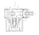
- FIG. 1 is a diagram schematically showing a master cylinder having an example of an embodiment of a stroke simulator according to the present invention, and a brake system using the master cylinder.
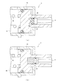
- FIG. 2 is a partially enlarged view of a portion II in FIG.
- the same components as those of the master cylinder having the stroke simulator shown in FIG. 4 described above are denoted by the same reference numerals, and detailed description thereof is omitted.
- the master cylinder 1 is used for the brake system 22 of this example.
- the primary hydraulic chamber 9 communicates with one system of brake cylinders 23 and 24, and the secondary hydraulic chamber 10 communicates with the other system of brake cylinders 25 and 26.
- a brake pedal 27 is connected to the input shaft 4. When the driver depresses the brake pedal 27, the input shaft 4 moves forward.
- the pedal feeling simulator unit 3 which is a stroke simulator of the master cylinder 1 is a rising load reducing unit 28 (which corresponds to the operation starting load reducing unit of the present invention) for reducing the operation starting load for starting the operation of the input shaft 4.
- the rising load reducing portion 28 of this example has a rising load reducing spring 29 that is a coil spring of an elastic member, and this rising load reducing spring 29 is disposed between the input shaft 4 and the simulator operating piston 14.
- the elastic coefficient of the rising load reducing spring 29 is set to be smaller than the elastic coefficient of the simulator operating piston return spring 16. Therefore, when the rising load reducing spring 29 is pressed by the input shaft 4, the rising load reducing spring 29 is elastic before the simulator operating piston return spring 16 is elastically bent and the simulator operating piston 14 starts moving forward.
- the simulator operating piston return spring 16 is substantially elastic.
- the simulator operating piston 14 starts to move forward by bending.
- the rising load reducing spring 29 starts to bend, so that the rising load (operation starting load) of the pedal sensation simulator unit 3 is the conventional pedal shown in FIG. Reduced from the rising load (operation start load) of the sensory simulator unit 3.
- a pedal feel characteristic diagram of the pedal feel simulator section 3 (characteristic diagram of reaction force against the stroke of the brake pedal 27).
- the pedal load simulator unit 3 stands up because the rising load reducing spring 29 having an elastic coefficient smaller than that of the simulator operating piston return spring 16 is elastically bent.
- the force at which the rising load reducing spring 29 starts to bend is F3 smaller than the force F1 at which the simulator operating piston return spring 16 starts to bend (F1> F3). That is, the rising load of the pedal sensation simulator unit 3 in this example is F3, which is smaller than the rising load of the conventional pedal sensation simulator unit 3.
- the bottoming load reduction spring 29 has a bottoming position ⁇ in which the first and second reaction force simulator springs 19 and 21 are substantially bent. It is set before starting.
- the bottoming position ⁇ of the rising load reducing spring 29 is set after the first and second reaction force simulator springs 19 and 21 are substantially bent, the first and second reaction force simulator springs 19 and 19
- the operation start load F4 of FIG. 21 is a characteristic diagram shown in FIG.
- the brake system 22 of this example further includes a power source 30, an electromagnetic switching valve 31, and a control unit (ECU) 32.
- the power source 30 supplies hydraulic fluid to the power chamber 13.
- the electromagnetic switching valve 31 selectively switches and communicates the power chamber 13 with either the reservoir tank 6 or the power source 30. In that case, when the brake system 22 in which the brake pedal 27 is not depressed is not operated, the electromagnetic switching valve 31 is not operated and the power chamber 13 is disconnected from the power source 30 and communicated with the reservoir tank 6. In addition, when the brake system 22 is operated when the brake pedal 27 is depressed, the electromagnetic switching valve 31 is operated to shut off the power chamber 13 from the reservoir tank 6 and communicate with the power source 30.
- the control unit (ECU) 32 drives the power source 30 and switches the electromagnetic switching valve 31 by the detection signal of the stroke of the input shaft 4 from the stroke sensor 5.
- the power chamber 13 is disconnected from the reservoir tank 6 and communicates with the power source 30, and hydraulic fluid is supplied from the power source 30 to the power chamber 13.
- the control unit (ECU) 32 calculates the hydraulic pressure corresponding to the braking force by the friction brake, as described above, based on the stroke of the input shaft 4 (that is, the depression amount of the brake pedal 27), and the power The hydraulic pressure in the chamber 13 is controlled to the calculated hydraulic pressure.
- the primary piston 7 operates to generate brake hydraulic pressure in the primary hydraulic pressure chamber 9 based on the depression amount of the brake pedal 27, and the secondary piston 8 operates to activate the secondary hydraulic pressure chamber. 10, the brake fluid pressure based on the depression amount of the brake pedal 27 is generated. These brake fluid pressures are supplied to the corresponding brake cylinders 23, 24, 25, and 26, and the wheels 33, 34, 35, and 36 are braked.
- the control unit (ECU) 32 stops the power source 30 and switches the electromagnetic switching valve 31 by the detection signal of the stroke of the input shaft 4 from the stroke sensor 5.
- the power chamber 13 is disconnected from the power source 30 and communicated with the reservoir tank 6, and the working fluid in the power chamber 13 is discharged to the reservoir tank 6.
- both the primary piston 7 and the secondary piston 8 are brought into the non-operating position shown in FIG. 1, and the primary hydraulic chamber 9 and the secondary hydraulic chamber 10 are both communicated with the reservoir tank 6, and the primary hydraulic chamber 9 and the secondary hydraulic pressure are connected.
- the fluid pressure in the chamber 10 becomes atmospheric pressure. Accordingly, the brakes of the wheels 33, 34, 35, and 36 are released.
- the rising load reducing section 28 having the rising load reducing spring 29 is provided. Therefore, the rising load of the pedal feel simulator section 3 can be reduced by the rising load reduction section 28 from the rising load of the conventional pedal feel simulator section 3 shown in FIG. Thereby, it is possible to smoothly start up the pedal feel simulation function by the pedal feel simulator section 3.
- the elastic coefficient or initial set load of the rising load reducing spring 29 can be arbitrarily set within a range smaller than the elastic coefficient or initial set load of the simulator operating piston return spring 16, respectively. Thereby, it is possible to arbitrarily set the rising load of the pedal feel simulator unit 3.
- the initial set load of the rising load reduction spring 29 is set to 0 (that is, the rising load reduction spring 29 is set to a free length when the pedal feeling simulator unit 3 is not operated), so that the pedal feeling simulator unit 3 is raised. It is possible to start from the 0 point.
- the brake operation of the vehicle can be performed with a good feeling by using the master cylinder 1 having the pedal feel simulator unit 3 that can smoothly start up the stroke simulation function for the brake system 22.
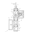
- FIG. 3A is a partially enlarged view showing another example of the embodiment of the stroke simulator according to the present invention
- FIG. 3B is a part showing still another example of the embodiment of the stroke simulator according to the present invention. It is an enlarged view.
- the rising load reducing unit 28 of the pedal feeling simulator unit 3 includes a rising load reducing spring 29, but in the example shown in FIG. 3A, the pedal feeling simulator unit 3 that is a stroke simulator.
- the rising load reducing portion 28 has a rubber plate 37 having a relatively low hardness in place of the spring.
- the rubber plate 37 is positioned between the input shaft 4 and the simulator operating piston 14 and attached to the input shaft 4.
- the rubber plate 37 is an elastic member, and its elastic coefficient is smaller than that of the simulator operating piston return spring 16.
- the simulator operating piston 14 is provided with a protrusion 14 a facing the rubber plate 37. When the input shaft 4 moves forward, the rubber plate 37 comes into contact with the protrusion 14a and elastically bends before the simulator operating piston 14 moves.
- the rising load reducing unit 28 of the pedal sensation simulator unit 3 that is a stroke simulator has a gas 38 of a predetermined pressure that functions as an elastic member instead of the spring, and the input shaft 4 and the simulator operating piston. 14 is sealed.
- the gas 38 is elastically compressed (compressed) before the simulator operating piston 14 moves.
- the present invention is not limited to the above-described examples, and any type can be used as long as the rising load reducing unit 28 of the pedal feeling simulator unit 3 operates before the simulator operating piston 14 moves forward. It can also be applied to a stroke simulator.
- the present invention is described in the claims, and various design changes can be made within the scope of the matters.
- a stroke simulator, a master cylinder, and a brake system according to the present invention are respectively a stroke simulator that generates a reaction force simulated according to depression of a pedal, a master cylinder having the stroke simulator, and a brake using the master cylinder. It can be suitably used for the system.
Landscapes
- Engineering & Computer Science (AREA)
- Mechanical Engineering (AREA)
- Physics & Mathematics (AREA)
- Fluid Mechanics (AREA)
- Transportation (AREA)
- General Engineering & Computer Science (AREA)
- Regulating Braking Force (AREA)
- Transmission Of Braking Force In Braking Systems (AREA)
- Braking Systems And Boosters (AREA)
- Braking Elements And Transmission Devices (AREA)
Abstract
本発明は、ストロークシミュレーション機能の作動開始をより一層スムーズに行うことを目的としており、本発明において、マスタシリンダ(1)のペダル感覚シミュレータ部(3)は立ち上がり荷重低減部(28)を有し、この立ち上がり荷重低減部(28)は立ち上がり荷重低減スプリング(29)を有する。立ち上がり荷重低減スプリング(29)の弾性係数は、シミュレータ作動ピストンリターンスプリング(16)の弾性係数より小さく設定されている。したがって、入力軸(4)により立ち上がり荷重低減スプリング(29)が押圧されると、立ち上がり荷重低減スプリング(29)は、シミュレータ作動ピストンリターンスプリング(16)が弾性的に撓んでシミュレータ作動ピストン(14)が前方へ移動開始する前に弾性的に撓み開始する。これにより、ペダル感覚シミュレータ部(3)の立ち上がり荷重が低減する。
Description
本発明は、ブレーキシステム等に用いられるペダルの踏み込みに応じた反力を発生させるストロークシミュレータの技術分野、このストロークシミュレータを有するマスタシリンダの技術分野、およびこのマスタシリンダを用いたブレーキシステムの技術分野に関するものである。なお、本発明の明細書の記載において、前後方向の関係は、ブレーキペダルの踏み込み時に入力軸が移動する方向を「前」、ブレーキペダルの踏み込み解除時に入力軸が戻る方向を「後」とする。
乗用車等の自動車においては、ハイブリッド車や電気自動車の開発が進んでいる。これに伴い、自動車のブレーキシステムにおいては、回生ブレーキと摩擦ブレーキとを協調して用いられる回生協調ブレーキシステムが種々開発されている。この回生協調ブレーキシステムは、ブレーキペダルの踏み込みストロークを検出し、検出されたストロークに基づいて、制御部(Electric control unit: ECU)が回生ブレーキによるブレーキ力と摩擦ブレーキによるブレーキ力とを演算し、演算されたブレーキ力で自動車にブレーキがかけられる。
このような回生協調ブレーキシステムにおいては、制御部がブレーキペダルの踏み込みストロークに基づいてブレーキ力を決定するため、ブレーキペダルの踏み込みストロークに応じた反力が運転者に伝達されない。そこで、運転者がブレーキペダルの踏み込みストロークに応じた反力を認識可能にするため、ペダル感覚シミュレータ部を有するマスタシリンダが提案されている(例えば、特許文献1参照)。
図4は、この特許文献1に記載されているペダル感覚シミュレータ部を有するマスタシリンダを模式的に示す図である。図中、1はマスタシリンダ、2は摩擦ブレーキのブレーキ液圧を発生するタンデムマスタシリンダ部、3はタンデムマスタシリンダ部2に一体的に設けられたペダル感覚シミュレータ部(ストロークシミュレータ)、4はブレーキペダル(図4には不図示)の踏み込みに応じてストロークする入力軸、5は入力軸4のストロークを検出するストロークセンサ、6はブレーキ液を貯留するリザーバタンクである。
タンデムマスタシリンダ部2は、従来周知のタンデムマスタシリンダと同様に、プライマリピストン7、セカンダリピストン8、プライマリピストン7とセカンダリピストン8で区画されるプライマリ液圧室9、セカンダリピストン8で区画されるセカンダリ液圧室10、プライマリピストン7を常時非作動位置の方へ付勢するプライマリスプリング11、セカンダリピストン8を常時非作動位置の方へ付勢するセカンダリスプリング12を有する。プライマリ液圧室9は一方のブレーキ系統のブレーキシリンダ(図4には不図示)に接続されるとともに、図示のプライマリピストン7の非作動位置でリザーバタンク6に連通される。そして、プライマリ液圧室9は、プライマリピストン7が前進するとリザーバタンク6から遮断されて、プライマリ液圧室9にブレーキ液圧が発生される。セカンダリ液圧室10は他方のブレーキ系統のブレーキシリンダ(図4には不図示)に接続されるとともに、図示のセカンダリピストン8の非作動位置でリザーバタンク6に連通される。そして、セカンダリ液圧室10は、セカンダリピストン8が前進するとリザーバタンク6から遮断されて、セカンダリ液圧室10にブレーキ液圧が発生される。
更に、タンデムマスタシリンダ部2は、プライマリピストン7とシリンダ壁との間に動力室13を有する。この動力室13には、ブレーキ作動時に図示しない動力源から作動液が供給される。その場合、作動液は、動力室13の液圧が制御部で演算された摩擦ブレーキによるブレーキ力に応じた液圧となるように供給される。
ペダル感覚シミュレータ部3は、入力軸4により作動されるシミュレータ作動ピストン14、シミュレータ作動ピストン14の作動によってシミュレータ作動液圧が発生するシミュレータ作動液圧室15、シミュレータ作動ピストン14を常時非作動位置の方へ付勢するコイルばねからなるシミュレータ作動ピストンリターンスプリング16、およびペダル感覚シミュレータカートリッジ17を有する。また、ペダル感覚シミュレータカートリッジ17は、シミュレータ作動液圧室15のシミュレータ作動液圧が作用される第1反力シミュレータピストン18(本発明の反力シミュレータ部材に相当)、第1反力シミュレータピストン18を常時非作動位置の方へ付勢する第1反力シミュレータスプリング19(本発明の反力シミュレータ部材に相当)、第1反力シミュレータスプリング19を支持する第2反力シミュレータピストン20(本発明の反力シミュレータ部材に相当)、第2反力シミュレータピストン20を常時非作動位置の方へ付勢する第2反力シミュレータスプリング21(本発明の反力シミュレータ部材に相当)を有する。
このペダル感覚シミュレータ部3においては、ブレーキペダルが踏み込まれない非作動時には、シミュレータ作動ピストン14は図4に示す非作動位置にある。この状態では、シミュレータ作動液圧室15はリザーバタンク6に連通し、シミュレータ作動液圧室15内はシミュレータ作動液圧が発生しなく大気圧となっている。したがって、第1反力シミュレータピストン18および第2反力シミュレータピストン20は図4に示す非作動位置にある。
そして、ブレーキペダルが踏み込まれると、入力軸4が前進(図4において左動)するので、シミュレータ作動ピストン14がシミュレータ作動ピストンリターンスプリング16を弾性的に撓ませながら前進(作動)する。シミュレータ作動ピストン14の作動でシミュレータ作動液圧室15がリザーバタンク6から遮断されると、シミュレータ作動液圧室15内にシミュレータ作動液圧が発生する。このシミュレータ作動液圧は第1反力シミュレータピストン18に作用する。シミュレータ作動液圧が所定の液圧に増大すると、このシミュレータ作動液圧により第1反力シミュレータピストン18は第1反力シミュレータスプリング19を押圧して弾性的に撓ませながら図4において下方へ移動(作動)するとともに、第1反力シミュレータピストン18の押圧力で第2反力シミュレータピストン20が第2反力シミュレータスプリング21を撓ませながら図4において下方へ移動(作動)する。これにより、第1および第2反力シミュレータスプリング19,21はそれらの撓み量に応じた力を第1反力シミュレータピストン18に反力として作用する。
そして、シミュレータ作動液圧による第1反力シミュレータピストン18への作用力と第1反力シミュレータスプリング19による第1反力シミュレータピストン18への作用力とがバランスすると、第1および第2反力シミュレータピストン18,20の移動が停止する。このとき、シミュレータ作動液圧室15内のシミュレータ作動液圧はブレーキペダルの踏み込みストロークに応じた液圧となる。そして、第1反力シミュレータピストン18の反力はシミュレータ作動液圧に変換されてシミュレータ作動ピストン14に作用し、更に反力はシミュレータ作動ピストン14から入力軸4を介してブレーキペダルに伝達される。これにより、運転者はブレーキペダルからブレーキペダルの踏み込みストロークに応じた反力を認識する。
このように構成されたペダル感覚シミュレータ部3におけるペダル感覚特性線図(つまり、ブレーキペダルのストロークSに対する反力Fの特性線図)は、図5(a)に示す特性線図となる。すなわち、ペダル感覚特性線図は、ペダル感覚シミュレータ部3の作動初期ではストロークSの増大に対して反力Fが比較的小さく、ストロークSが所定量大きくなると、ストロークSの増大に対して反力Fが比較的大きくなるように湾曲した特性曲線を描く。
一方、このマスタシリンダ1においては、ブレーキペダルが踏み込まれない非作動時には、タンデムマスタシリンダ部2およびペダル感覚シミュレータ部3はともに図4に示す非作動状態にある。すなわち、動力室13に動力源から作動液が供給されなく、プライマリピストン7およびセカンダリピストン8はともに図4に示す非作動位置にある。したがってプライマリ液圧室9およびセカンダリ液圧室10はともにリザーバタンク6に連通し、プライマリ液圧室9およびセカンダリ液圧室10内にはブレーキ液圧は発生していない。また、シミュレータ作動液圧室15はリザーバタンク6に連通し、シミュレータ作動液圧室15内にはシミュレータ作動液圧は発生していない。
また、ブレーキペダルが踏み込まれると、入力軸4が前方へストロークする。この入力軸4のストロークがストロークセンサ5により検出される。図示しない制御部は、ストロークセンサ5からの入力軸4のストローク(つまり、ブレーキペダルの踏み込みストローク)に基づいて動力源を駆動制御する。これにより、動力源から作動液が動力室13に供給され、プライマリピストン7およびセカンダリピストン8が前進する。すると、プライマリ液圧室9およびセカンダリ液圧室10がともにリザーバタンク6から遮断されて、プライマリ液圧室9およびセカンダリ液圧室10内にブレーキ液圧が発生する。これらのブレーキ液圧がそれぞれ2系統の対応するブレーキシリンダに供給され、自動車の対応する車輪にブレーキがかけられる。
動力室13内の作動液圧がブレーキペダルの踏み込みストロークに対応した液圧となると、制御部は動力源を停止する。すると、プライマリピストン7およびセカンダリピストン8がともに停止し、プライマリ液圧室9およびセカンダリ液圧室10内のブレーキ液圧はともにブレーキペダルの踏み込みストロークに対応した液圧となる。すなわち、ブレーキペダルの踏み込みストロークに対応したブレーキ力でブレーキが車輪にかけられる。
このとき、前述のようにペダル感覚シミュレータ部3はブレーキペダルの踏み込みストロークに対応した反力をブレーキペダルに伝達する。したがって、運転者はこの反力を認識して、ブレーキペダルの踏み込みストロークに対応したブレーキ力でブレーキが車輪にかけられることを感知する。
ブレーキペダルが解放されると、入力軸4が後方(非作動位置の方)へストロークし、この入力軸4のストロークがストロークセンサ5により検出される。制御部は、ストロークセンサ5で検出されたストロークに基づいて図示しない制御弁を制御し、動力室13内の作動液をリザーバタンク6に排出する。これにより、動力室13内の液圧が低下し、プライマリピストン7およびセカンダリピストン8がそれぞれプライマリスプリング11およびセカンダリスプリング12の付勢力で後退する。動力室13内の液圧が大気圧となると、プライマリピストン7およびセカンダリピストン8がともに図4に示す非作動位置となり、車輪のブレーキが解除する。
一方、入力軸4が後方へストロークすることで、シミュレータ作動ピストンリターンスプリング16の付勢力でシミュレータ作動ピストン14が後退する。そして、シミュレータ作動ピストン14が非作動位置近傍になると、シミュレータ作動液圧室15がリザーバタンク6に連通し、シミュレータ作動液圧室15内のシミュレータ作動液圧が低下する。シミュレータ作動ピストン14が図4に示す非作動位置になった状態では、シミュレータ作動液圧室15の液圧は大気圧となる。これにより、第1反力シミュレータピストン18および第2反力シミュレータピストン20もともに図4に示す非作動位置となる。なお、各構成要素に用られている用語および符号は、いずれも特許文献1に記載された用語および符号と同じ用語および符号ではない。
ところで、特許文献1に記載のペダル感覚シミュレータ部3は、シミュレータ作動ピストンリターンスプリング16、第1反力シミュレータスプリング19、および第2反力シミュレータスプリング21の複数のスプリングを有している。一方、ペダル感覚シミュレータ部3が立ち上がる(作動開始する)ためには、シミュレータ作動ピストン14が作動する必要がある。このため、ペダル感覚シミュレータ部3が立ち上がるためには、ブレーキペダルの踏み込みストロークによりこれらの複数のスプリングが撓んでシミュレータ作動ピストン14が作動しなければならない。
特に、シミュレータ作動ピストン14には、シールによるシミュレータ作動ピストン14の摺動抵抗が作用するため、シミュレータ作動ピストン14を非作動位置に確実に戻らせるには、シミュレータ作動ピストンリターンスプリング16のばね荷重を比較的大きくする必要がある。このため、シミュレータ作動ピストンリターンスプリング16の初期設定荷重は比較的大きい。
したがって、ペダル感覚シミュレータ部3の立ち上がり時(作動開始時)に、ブレーキペダルの踏み込み力によりシミュレータ作動ピストン14がシミュレータ作動ピストンリターンスプリング16を押圧する力は、少なくともシミュレータ作動ピストンリターンスプリング16の初期設定荷重を超える大きさが必要となる。すなわち、図5(a)のVB部を拡大した図5(b)に示すようにペダル感覚シミュレータ部3の立ち上がり時には、シミュレータ作動ピストン14がシミュレータ作動ピストンリターンスプリング16を押圧する押圧力(反力に等しい)は、シミュレータ作動ピストンリターンスプリング16が撓み開始する力F1を超える大きさである必要がある。なお、F2は、第1および第2反力シミュレータスプリング19,21が撓み開始する力である。
しかしながら、このようにシミュレータ作動ピストンリターンスプリング16の初期設定荷重が大きいと、シミュレータ作動ピストン14が撓み開始する力F1が大きくなる。つまり、ペダル感覚シミュレータ部3の立ち上がり荷重が大きくなる。このため、ペダル感覚シミュレータ部3によるペダル感覚シミュレーション機能の立ち上がりがスムーズに行われない。
本発明はこのような事情に鑑みてなされたものであって、その目的は、ストロークシミュレーション機能の作動開始をより一層スムーズに行うことができるストロークシミュレータ、このストロークシミュレータを有するマスタシリンダ、およびこのマスタシリンダを用いたブレーキシステムを提供することである。
前述の課題を解決するために、本発明に係るストロークシミュレータは、入力が加えられて作動する入力軸と、前記入力軸により作動されるシミュレータ作動ピストンと、
前記シミュレータ作動ピストンを非作動位置の方向に付勢するシミュレータ作動ピストンリターンスプリングと、前記シミュレータ作動ピストンの作動により、前記入力軸の入力に基づいた反力を前記シミュレータ作動ピストンに出力する反力シミュレータ部材と、
前記入力軸が作動開始する作動開始荷重を低減する作動開始荷重低減部とを有することを特徴としている。
前記シミュレータ作動ピストンを非作動位置の方向に付勢するシミュレータ作動ピストンリターンスプリングと、前記シミュレータ作動ピストンの作動により、前記入力軸の入力に基づいた反力を前記シミュレータ作動ピストンに出力する反力シミュレータ部材と、
前記入力軸が作動開始する作動開始荷重を低減する作動開始荷重低減部とを有することを特徴としている。
また、本発明に係るストロークシミュレータは、前記作動開始荷重低減部が、前記入力軸と前記シミュレータ作動ピストンとの間に配設されることを特徴としている。
更に、本発明に係るストロークシミュレータは、前記作動開始荷重低減部が、前記シミュレータ作動ピストンリターンスプリングの弾性係数より小さい弾性係数の弾性部材を有することを特徴としている。
更に、本発明に係るストロークシミュレータは、前記作動開始荷重低減部が、前記シミュレータ作動ピストンリターンスプリングの弾性係数より小さい弾性係数の弾性部材を有することを特徴としている。
更に、本発明に係るストロークシミュレータは、前記弾性部材が、コイルスプリングからなる作動開始荷重低減スプリングであることを特徴としている。
更に、本発明に係るストロークシミュレータは、前記弾性部材がゴム部材であることを特徴としている。
更に、本発明に係るストロークシミュレータは、前記弾性部材が前記入力軸と前記シミュレータ作動ピストンとの間に密封されたガスであることを特徴としている。
更に、本発明に係るストロークシミュレータは、前記弾性部材がゴム部材であることを特徴としている。
更に、本発明に係るストロークシミュレータは、前記弾性部材が前記入力軸と前記シミュレータ作動ピストンとの間に密封されたガスであることを特徴としている。
更に、本発明に係るストロークシミュレータは、前記シミュレータ作動ピストンの作動でシミュレータ作動液圧が発生されるシミュレータ作動液圧室を有し、前記反力シミュレータ部材が、前記シミュレータ作動液圧室の前記シミュレータ作動液圧が作用されて作動する反力シミュレータピストンと、前記反力シミュレータピストンにより押圧されて撓んで反力を発生する反力シミュレータスプリングとを有することを特徴としている。
更に、本発明に係るマスタシリンダは、入力軸の入力に基づいた反力を出力するストロークシミュレータと前記入力軸の入力に基づいた液圧を発生するマスタシリンダピストンとを有するマスタシリンダにおいて、前記ストロークシミュレータが、前述の本発明のストロークシミュレータのいずれか1つであることを特徴としている。
更に、本発明に係るブレーキシステムは、ブレーキペダルと、前記ブレーキペダルの踏み込みで作動して前記ブレーキペダルの踏み込みに基づいたブレーキ液圧を発生するマスタシリンダと、前記マスタシリンダで発生された前記ブレーキ液圧でブレーキ力を発生するブレーキシリンダとを備えるブレーキシステムにおいて、前記マスタシリンダが、前述のマスタシリンダであることを特徴としている。
このように構成された本発明に係るストロークシミュレータ、これを有するマスタシリンダ、およびブレーキシステムによれば、入力軸が作動開始する作動開始荷重を低減する作動開始荷重低減部が設けられる。したがって、この作動開始荷重低減部によりストロークシミュレータの作動開始荷重を、従来のストロークシミュレータの作動開始荷重より低減することができる。これにより、ストロークシミュレータによるストロークシミュレーション機能の作動開始をスムーズに行うことが可能となる。
また、作動開始荷重低減部の弾性部材の弾性係数あるいは初期設定荷重を、それぞれシミュレータ作動ピストンリターンスプリングの弾性係数あるいは初期設定荷重より小さい範囲内で任意に設定することができる。これにより、ストロークシミュレータの作動開始荷重を任意に設定することが可能となる。特に、作動開始荷重低減部の弾性部材の初期設定荷重を0にする(つまり、ストロークの非作動時に弾性部材を自由長に設定する)ことで、ストロークシミュレータを初期設定荷重の0点から作動開始することが可能となる。
更に、ストロークシミュレーション機能の作動開始をスムーズに行うことができるストロークシミュレータを有するマスタシリンダをブレーキシステムに用いることで、車両のブレーキ操作を良好なフィーリングで行うことができる。
以下、図面を用いて本発明を実施するための形態について説明する。
図1は本発明に係るストロークシミュレータの実施の形態の一例を有するマスタシリンダ、およびこのマスタシリンダを用いたブレーキシステムを模式的に示す図である。また、図2は図1におけるII部の部分拡大図である。なお、前述の図4に示すストロークシミュレータを有するマスタシリンダの構成要素と同じ本発明の構成要素には、同じ符号を付すことでそれらの詳細な説明は省略する。
図1は本発明に係るストロークシミュレータの実施の形態の一例を有するマスタシリンダ、およびこのマスタシリンダを用いたブレーキシステムを模式的に示す図である。また、図2は図1におけるII部の部分拡大図である。なお、前述の図4に示すストロークシミュレータを有するマスタシリンダの構成要素と同じ本発明の構成要素には、同じ符号を付すことでそれらの詳細な説明は省略する。
図1および図2に示すように、この例のブレーキシステム22にはマスタシリンダ1が用いられる。このマスタシリンダ1のタンデムマスタシリンダ部2では、プライマリ液圧室9が一方の系統のブレーキシリンダ23,24に連通しているとともに、セカンダリ液圧室10が他方の系統のブレーキシリンダ25,26に連通している。
また、入力軸4にはブレーキペダル27が連結されている。運転者がブレーキペダル27を踏み込むことで、入力軸4が前進するようになっている。
また、入力軸4にはブレーキペダル27が連結されている。運転者がブレーキペダル27を踏み込むことで、入力軸4が前進するようになっている。
更に、マスタシリンダ1のストロークシミュレータであるペダル感覚シミュレータ部3は、入力軸4が作動開始する作動開始する作動開始荷重を低減する立ち上がり荷重低減部28(本発明の作動開始荷重低減部に相当)を有する。この例の立ち上がり荷重低減部28は弾性部材のコイルスプリングである立ち上がり荷重低減スプリング29を有し、この立ち上がり荷重低減スプリング29は入力軸4とシミュレータ作動ピストン14との間に配設される。この立ち上がり荷重低減スプリング29の弾性係数は、シミュレータ作動ピストンリターンスプリング16の弾性係数より小さく設定されている。したがって、入力軸4により立ち上がり荷重低減スプリング29が押圧されると、立ち上がり荷重低減スプリング29は、シミュレータ作動ピストンリターンスプリング16が弾性的に撓んでシミュレータ作動ピストン14が前方へ移動開始する前に弾性的に撓み開始する。そして、立ち上がり荷重低減スプリング29がボトミングする(つまり、立ち上がり荷重低減スプリング29が最大限に撓んで、立ち上がり荷重低減スプリング29の撓みが終了する)と、実質的にシミュレータ作動ピストンリターンスプリング16が弾性的に撓んでシミュレータ作動ピストン14が前方へ移動開始するようになっている。
このようにシミュレータ作動ピストン14が前方へ移動開始する前に、立ち上がり荷重低減スプリング29が撓み開始することで、ペダル感覚シミュレータ部3の立ち上がり荷重(作動開始荷重)が、図4に示す従来のペダル感覚シミュレータ部3の立ち上がり荷重(作動開始荷重)より低減する。
これをペダル感覚シミュレータ部3のペダル感覚特性線図(ブレーキペダル27のストロークに対する反力の特性線図)で説明する。図5(c)に示すように、最初にシミュレータ作動ピストンリターンスプリング16の弾性係数より小さい弾性係数の立ち上がり荷重低減スプリング29が弾性的に撓むことで、ペダル感覚シミュレータ部3が立ち上がる。立ち上がり荷重低減スプリング29が撓み開始する力は、シミュレータ作動ピストンリターンスプリング16が撓み開始する力F1より小さいF3である(F1>F3)。すなわち、この例のペダル感覚シミュレータ部3の立ち上がり荷重はF3となり、従来のペダル感覚シミュレータ部3の立ち上がり荷重より小さい。
なお、図5(c)に示すようにこの例のペダル感覚シミュレータ部3では、立ち上がり荷重低減スプリング29のボトミング位置αは、第1および第2反力シミュレータスプリング19,21がともに実質的に撓む前に設定されている。また、立ち上がり荷重低減スプリング29のボトミング位置αが、第1および第2反力シミュレータスプリング19,21がともに実質的に撓んだ後に設定される場合、第1および第2反力シミュレータスプリング19,21の作動開始荷重F4は、図5(d)に示す特性線図となる。
図1に示すように、更にこの例のブレーキシステム22は、動力源30、電磁切換弁31、および制御部(ECU)32を備えている。動力源30は作動液を動力室13に供給する。電磁切換弁31は動力室13をリザーバタンク6および動力源30のいずれか一方に選択的に切り換え連通させる。その場合、ブレーキペダル27が踏み込まれないブレーキシステム22の非作動時は、電磁切換弁31は作動しなく、動力室13を動力源30から遮断しリザーバタンク6に連通する。また、ブレーキペダル27が踏み込まれたブレーキシステム22の作動時は、電磁切換弁31は作動し、動力室13をリザーバタンク6から遮断して動力源30に連通する。
制御部(ECU)32は、ブレーキペダル27の踏み込み時、ストロークセンサ5からの入力軸4のストロークの検出信号により、動力源30を駆動するとともに電磁切換弁31を切換作動する。これにより、動力室13がリザーバタンク6から遮断されて動力源30に連通し、動力源30から作動液が動力室13に供給される。その場合、制御部(ECU)32は、入力軸4のストローク(つまり、ブレーキペダル27の踏み込み量)に基づいて、前述と同様に摩擦ブレーキによるブレーキ力に応じた液圧を演算するとともに、動力室13の液圧が演算された液圧に制御される。動力室13の液圧により、プライマリピストン7が作動してプライマリ液圧室9にブレーキペダル27の踏み込み量に基づいたブレーキ液圧が発生されるとともに、セカンダリピストン8が作動してセカンダリ液圧室10にブレーキペダル27の踏み込み量に基づいたブレーキ液圧が発生される。これらのブレーキ液圧がそれぞれ対応するブレーキシリンダ23,24,25,26に供給され、車輪33,34,35,36にブレーキがかけられる。
また、制御部(ECU)32は、ブレーキペダル27の解放時、ストロークセンサ5からの入力軸4のストロークの検出信号により、動力源30を停止するとともに電磁切換弁31を切換作動する。これにより、動力室13が動力源30から遮断され、かつリザーバタンク6に連通され、動力室13内の作動液がリザーバタンク6に排出される。すると、プライマリピストン7およびセカンダリピストン8がいずれも図1に示す非作動位置となり、プライマリ液圧室9およびセカンダリ液圧室10がともにリザーバタンク6に連通し、プライマリ液圧室9およびセカンダリ液圧室10内の液圧が大気圧となる。したがって、車輪33,34,35,36のブレーキが解除される。
この例のマスタシリンダ1およびペダル感覚シミュレータ部3の他の構成および他の作用効果は、前述の図4に示すマスタシリンダ1およびペダル感覚シミュレータ部3(つまり、特許文献1に記載のペダル感覚シミュレータを有するマスタシリンダ)と同じである。また、タンデムマスタシリンダ部2よりブレーキシリンダ23,24,25,26までのブレーキシステムの他の構成および他の作用効果は、従来周知の一般的なタンデムマスタシリンダよりブレーキシリンダまでのブレーキシステムと同じである。
この例のペダル感覚シミュレータ部3、これを有するマスタシリンダ1、およびブレーキシステム22によれば、立ち上がり荷重低減スプリング29を有する立ち上がり荷重低減部28が設けられる。したがって、この立ち上がり荷重低減部28により、ペダル感覚シミュレータ部3の立ち上がり荷重を、図4に示す従来のペダル感覚シミュレータ部3の立ち上がり荷重より低減することができる。これにより、ペダル感覚シミュレータ部3によるペダル感覚シミュレーション機能の立ち上がりをスムーズに行うことが可能となる。
また、立ち上がり荷重低減スプリング29の弾性係数あるいは初期設定荷重を、それぞれシミュレータ作動ピストンリターンスプリング16の弾性係数あるいは初期設定荷重より小さい範囲内で任意に設定することができる。これにより、ペダル感覚シミュレータ部3の立ち上がり荷重を任意に設定することが可能となる。特に、立ち上がり荷重低減スプリング29の初期設定荷重を0にする(つまり、ペダル感覚シミュレータ部3の非作動時に立ち上がり荷重低減スプリング29を自由長に設定する)ことで、ペダル感覚シミュレータ部3を立ち上がり荷重の0点から立ち上げることが可能となる。
更に、ストロークシミュレーション機能の立ち上がりをスムーズに行うことができるペダル感覚シミュレータ部3を有するマスタシリンダ1をブレーキシステム22に用いることで、車両のブレーキ操作を良好なフィーリングで行うことができる。
図3(a)は本発明に係るストロークシミュレータの実施の形態の他の例を示す部分拡大図、図3(b)は本発明に係るストロークシミュレータの実施の形態の更に他の例を示す部分拡大図である。
図1および図2に示す例では、ペダル感覚シミュレータ部3の立ち上がり荷重低減部28が立ち上がり荷重低減スプリング29を有するが、図3(a)に示す例では、ストロークシミュレータであるペダル感覚シミュレータ部3の立ち上がり荷重低減部28は、スプリングに代えて硬度の比較的低いゴム板37を有する。その場合、ゴム板37は入力軸4とシミュレータ作動ピストン14との間に位置して入力軸4に取り付けられる。このゴム板37は弾性部材であり、その弾性係数はシミュレータ作動ピストンリターンスプリング16の弾性係数より小さい。また、シミュレータ作動ピストン14には突起14aがゴム板37に対向して設けられる。そして、入力軸4の前方移動時に、シミュレータ作動ピストン14が移動する前にゴム板37が突起14aに当接して弾性的に撓むようになっている。
この例のマスタシリンダ1およびペダル感覚シミュレータ部3の他の構成および他の作用効果は、前述の図1および図2に示すマスタシリンダ1およびペダル感覚シミュレータ部3と同じである。また、タンデムマスタシリンダ部2よりブレーキシリンダ23,24,25,26までのブレーキシステムの他の構成および他の作用効果は、従来周知の一般的なタンデムマスタシリンダよりブレーキシリンダまでのブレーキシステムと同じである。
また図3(b)に示す例では、ストロークシミュレータであるペダル感覚シミュレータ部3の立ち上がり荷重低減部28は、スプリングに代えて弾性部材として機能する所定圧のガス38が入力軸4とシミュレータ作動ピストン14との間に密封されている。そして、入力軸4の前方移動時に、シミュレータ作動ピストン14が移動する前にガス38が弾性的に圧縮(圧縮変形)されるようになっている。
この例のマスタシリンダ1およびペダル感覚シミュレータ部3の他の構成および他の作用効果は、前述の図1および図2に示すマスタシリンダ1およびペダル感覚シミュレータ部3と同じである。また、タンデムマスタシリンダ部2よりブレーキシリンダ23,24,25,26までのブレーキシステムの他の構成および他の作用効果は、従来周知の一般的なタンデムマスタシリンダよりブレーキシリンダまでのブレーキシステムと同じである。なお、ガスを弾性変形可能な袋状の容器に封入したガスカートリッジを形成し、このガスカートリッジを入力軸4とシミュレータ作動ピストン14との間に配設することもできる。
なお、本発明は前述の各例に限定されることはなく、シミュレータ作動ピストン14が前方へ移動する前にペダル感覚シミュレータ部3の立ち上がり荷重低減部28が作動するものであれば、どのようなストロークシミュレータにも適用することができる。要は、本発明は特許請求の範囲に記載されて事項の範囲内で種々設計変更が可能である。
本発明に係るストロークシミュレータ、マスタシリンダ、およびブレーキシステムは、それぞれ、ペダルの踏み込みに応じてシミュレートした反力を発生させるストロークシミュレータ、このストロークシミュレータを有するマスタシリンダ、およびこのマスタシリンダを用いたブレーキシステムに好適に利用可能である。
Claims (9)
- 入力が加えられて作動する入力軸と、
前記入力軸により作動されるシミュレータ作動ピストンと、
前記シミュレータ作動ピストンを非作動位置の方向に付勢するシミュレータ作動ピストンリターンスプリングと、
前記シミュレータ作動ピストンの作動により、前記入力軸の入力に基づいた反力を前記シミュレータ作動ピストンに出力する反力シミュレータ部材と、
前記入力軸が作動開始する作動開始荷重を低減する作動開始荷重低減部と
を有することを特徴とするストロークシミュレータ。 - 前記作動開始荷重低減部は、前記入力軸と前記シミュレータ作動ピストンとの間に配設されることを特徴とする請求項1に記載のストロークシミュレータ。
- 前記作動開始荷重低減部は、前記シミュレータ作動ピストンリターンスプリングの弾性係数より小さい弾性係数の弾性部材を有することを特徴とする請求項1または2に記載のストロークシミュレータ。
- 前記弾性部材は、コイルスプリングからなる作動開始荷重低減スプリングであることを特徴とする請求項3に記載のストロークシミュレータ。
- 前記弾性部材は、ゴム部材であることを特徴とする請求項3に記載のストロークシミュレータ。
- 前記弾性部材は、前記入力軸と前記シミュレータ作動ピストンとの間に密封されたガスであることを特徴とする請求項3に記載のストロークシミュレータ。
- 前記シミュレータ作動ピストンの作動でシミュレータ作動液圧が発生されるシミュレータ作動液圧室を有し、
前記反力シミュレータ部材は、前記シミュレータ作動液圧室の前記シミュレータ作動液圧が作用されて作動する反力シミュレータピストンと、前記反力シミュレータピストンにより押圧されて撓んで反力を発生する反力シミュレータスプリングとを有する、
ことを特徴とする請求項1ないし6のいずれか1項に記載のストロークシミュレータ。 - 入力軸の入力に基づいた反力を出力するストロークシミュレータと前記入力軸の入力に基づいた液圧を発生するマスタシリンダピストンとを有するマスタシリンダにおいて、
前記ストロークシミュレータは、請求項1ないし7のいずれか1項に記載のストロークシミュレータであることを特徴とするマスタシリンダ。 - ブレーキペダルと、前記ブレーキペダルの踏み込みで作動して前記ブレーキペダルの踏み込みに基づいたブレーキ液圧を発生するマスタシリンダと、前記マスタシリンダで発生された前記ブレーキ液圧でブレーキ力を発生するブレーキシリンダとを備えるブレーキシステムにおいて、
前記マスタシリンダは、請求項8に記載のマスタシリンダであることを特徴とするブレーキシステム。
Priority Applications (3)
| Application Number | Priority Date | Filing Date | Title |
|---|---|---|---|
| CN201280023403.7A CN103562027A (zh) | 2011-05-16 | 2012-05-14 | 行程仿真器、具有该行程仿真器的主缸、以及使用该主缸的制动系统 |
| US14/117,673 US20140109565A1 (en) | 2011-05-16 | 2012-05-14 | Stroke simulator, master cylinder having this stroke simulator, and brake system using this master cylinder |
| EP12786403.1A EP2711256A4 (en) | 2011-05-16 | 2012-05-14 | RUNNING SIMULATOR, MASTER CYLINDER COMPRISING IT AND BRAKE SYSTEM USING THE MASTER CYLINDER |
Applications Claiming Priority (2)
| Application Number | Priority Date | Filing Date | Title |
|---|---|---|---|
| JP2011109507A JP2012240451A (ja) | 2011-05-16 | 2011-05-16 | ストロークシミュレータ、このストロークシミュレータを有するマスタシリンダ、およびこのマスタシリンダを用いたブレーキシステム |
| JP2011-109507 | 2011-05-16 |
Publications (1)
| Publication Number | Publication Date |
|---|---|
| WO2012157609A1 true WO2012157609A1 (ja) | 2012-11-22 |
Family
ID=47176926
Family Applications (1)
| Application Number | Title | Priority Date | Filing Date |
|---|---|---|---|
| PCT/JP2012/062302 Ceased WO2012157609A1 (ja) | 2011-05-16 | 2012-05-14 | ストロークシミュレータ、このストロークシミュレータを有するマスタシリンダ、およびこのマスタシリンダを用いたブレーキシステム |
Country Status (5)
| Country | Link |
|---|---|
| US (1) | US20140109565A1 (ja) |
| EP (1) | EP2711256A4 (ja) |
| JP (1) | JP2012240451A (ja) |
| CN (1) | CN103562027A (ja) |
| WO (1) | WO2012157609A1 (ja) |
Cited By (2)
| Publication number | Priority date | Publication date | Assignee | Title |
|---|---|---|---|---|
| EP3418139A1 (de) * | 2013-11-28 | 2018-12-26 | Lucas Automotive GmbH | Elektrohydraulische kraftfahrzeug-bremsanlage und betriebsverfahren dafür. |
| CN113997917A (zh) * | 2021-11-24 | 2022-02-01 | 吉林东光奥威汽车制动系统有限公司 | 一种可机械液压解耦的电子制动助力器的机械液压部件 |
Families Citing this family (4)
| Publication number | Priority date | Publication date | Assignee | Title |
|---|---|---|---|---|
| KR101417376B1 (ko) * | 2012-10-26 | 2014-07-08 | 현대자동차주식회사 | 다단 직렬형 스프링을 이용한 페달 시뮬레이터 |
| KR101402538B1 (ko) * | 2012-11-19 | 2014-06-02 | 주식회사 만도 | 페달 시뮬레이터 |
| CN112277906B (zh) * | 2019-12-31 | 2022-06-10 | 京西重工(上海)有限公司 | 踏板制动组件 |
| CN113310686B (zh) * | 2021-06-30 | 2025-04-04 | 重庆青山工业有限责任公司 | 一种液压实时负载模拟装置 |
Citations (5)
| Publication number | Priority date | Publication date | Assignee | Title |
|---|---|---|---|---|
| JP2004001694A (ja) * | 2002-02-25 | 2004-01-08 | Robert Bosch Gmbh | 改良されたペダル感覚シミュレーション手段を備える電気油圧制動システム用のマスターシリンダと、このようなマスターシリンダを備えた電気油圧制動システム |
| JP2008030599A (ja) * | 2006-07-28 | 2008-02-14 | Hitachi Ltd | 電動倍力装置 |
| JP2008087760A (ja) * | 2007-11-05 | 2008-04-17 | Hitachi Ltd | ブレーキ |
| WO2010069740A1 (de) * | 2008-12-18 | 2010-06-24 | Robert Bosch Gmbh | Bremskraftverstärker |
| JP2010241314A (ja) * | 2009-04-08 | 2010-10-28 | Honda Motor Co Ltd | Bbw式ブレーキ装置 |
Family Cites Families (9)
| Publication number | Priority date | Publication date | Assignee | Title |
|---|---|---|---|---|
| EP0956223B2 (en) * | 1997-02-07 | 2009-06-17 | Kelsey Hayes Company | Pedal simulator using spring with non-linear response |
| FR2772706B1 (fr) * | 1997-12-22 | 2000-02-11 | Bosch Syst Freinage | Maitre-cylindre pour installation de freinage electro-hydraulique de vehicule automobile |
| JP3932692B2 (ja) * | 1998-03-10 | 2007-06-20 | アイシン精機株式会社 | 車両ブレーキ装置 |
| JP3972859B2 (ja) * | 2003-05-14 | 2007-09-05 | 株式会社アドヴィックス | ストロークシミュレータ |
| CN100577484C (zh) * | 2004-10-15 | 2010-01-06 | 大陆-特韦斯贸易合伙股份公司及两合公司 | 用于机动车辆的制动设备 |
| DE102005026314C5 (de) * | 2005-06-07 | 2008-09-25 | Lkh-Kunststoffwerk Gmbh & Co. Kg | Tauchkolben aus Kunststoff für eine Luftfeder |
| JP4937801B2 (ja) * | 2007-03-19 | 2012-05-23 | パスカルエンジニアリング株式会社 | アクチュエータ、アクチュエータを備えたアンクランプ装置および加工装置 |
| JP4900320B2 (ja) * | 2008-05-29 | 2012-03-21 | トヨタ自動車株式会社 | マスタシリンダ |
| JP4952665B2 (ja) * | 2008-06-20 | 2012-06-13 | トヨタ自動車株式会社 | ストロークシミュレータ及び車両用制動装置 |
-
2011
- 2011-05-16 JP JP2011109507A patent/JP2012240451A/ja active Pending
-
2012
- 2012-05-14 EP EP12786403.1A patent/EP2711256A4/en not_active Withdrawn
- 2012-05-14 WO PCT/JP2012/062302 patent/WO2012157609A1/ja not_active Ceased
- 2012-05-14 US US14/117,673 patent/US20140109565A1/en not_active Abandoned
- 2012-05-14 CN CN201280023403.7A patent/CN103562027A/zh active Pending
Patent Citations (6)
| Publication number | Priority date | Publication date | Assignee | Title |
|---|---|---|---|---|
| JP2004001694A (ja) * | 2002-02-25 | 2004-01-08 | Robert Bosch Gmbh | 改良されたペダル感覚シミュレーション手段を備える電気油圧制動システム用のマスターシリンダと、このようなマスターシリンダを備えた電気油圧制動システム |
| JP4510388B2 (ja) | 2002-02-25 | 2010-07-21 | ロバート ボッシュ ゲゼルシャフト ミット ベシュレンクテル ハフツング | 改良されたペダル感覚シミュレーション手段を備える電気油圧制動システム用のマスターシリンダと、このようなマスターシリンダを備えた電気油圧制動システム |
| JP2008030599A (ja) * | 2006-07-28 | 2008-02-14 | Hitachi Ltd | 電動倍力装置 |
| JP2008087760A (ja) * | 2007-11-05 | 2008-04-17 | Hitachi Ltd | ブレーキ |
| WO2010069740A1 (de) * | 2008-12-18 | 2010-06-24 | Robert Bosch Gmbh | Bremskraftverstärker |
| JP2010241314A (ja) * | 2009-04-08 | 2010-10-28 | Honda Motor Co Ltd | Bbw式ブレーキ装置 |
Non-Patent Citations (1)
| Title |
|---|
| See also references of EP2711256A4 |
Cited By (3)
| Publication number | Priority date | Publication date | Assignee | Title |
|---|---|---|---|---|
| EP3418139A1 (de) * | 2013-11-28 | 2018-12-26 | Lucas Automotive GmbH | Elektrohydraulische kraftfahrzeug-bremsanlage und betriebsverfahren dafür. |
| CN113997917A (zh) * | 2021-11-24 | 2022-02-01 | 吉林东光奥威汽车制动系统有限公司 | 一种可机械液压解耦的电子制动助力器的机械液压部件 |
| CN113997917B (zh) * | 2021-11-24 | 2023-12-19 | 吉林东光奥威汽车制动系统有限公司 | 一种可机械液压解耦的电子制动助力器的机械液压部件 |
Also Published As
| Publication number | Publication date |
|---|---|
| CN103562027A (zh) | 2014-02-05 |
| JP2012240451A (ja) | 2012-12-10 |
| EP2711256A1 (en) | 2014-03-26 |
| EP2711256A4 (en) | 2016-05-11 |
| US20140109565A1 (en) | 2014-04-24 |
Similar Documents
| Publication | Publication Date | Title |
|---|---|---|
| US9254827B2 (en) | Operation of a brake booster as a pedal simulator | |
| EP2548776B1 (en) | Stroke simulator, master cylinder having stroke simulator and brake system using master cylinder | |
| WO2012157609A1 (ja) | ストロークシミュレータ、このストロークシミュレータを有するマスタシリンダ、およびこのマスタシリンダを用いたブレーキシステム | |
| US9914439B2 (en) | Brake system having pedal simulator | |
| US9845086B2 (en) | Brake booster and method for operating a brake booster | |
| US20140144732A1 (en) | Pedal Travel Simulator, Actuating Unit for a Hydraulic Brake System and Brake System | |
| US9868428B2 (en) | Brake booster and method for operating a brake booster | |
| CN102235450B (zh) | 刹车致动器单元 | |
| CN108860100B (zh) | 用于制动系统的致动单元 | |
| US9302663B2 (en) | Hydraulic brake device for vehicle | |
| KR20070102715A (ko) | 차량의 브레이크 시스템 | |
| US20120137673A1 (en) | Brake System for Motor Vehicles | |
| JP3783918B2 (ja) | ブレーキ液圧発生装置 | |
| JPWO2010055842A1 (ja) | ブレーキ装置 | |
| JP2012240451A5 (ja) | ||
| CN103547494B (zh) | 行程仿真器、具有该行程仿真器的主缸、以及使用该主缸的制动系统 | |
| KR101568426B1 (ko) | 회생제동용 제동장치의 공압타입 페일-세이프구현기구 | |
| WO2010003517A3 (de) | Bremskraftverstärker für eine kraftfahrzeugbremsanlage und entsprechende kraftfahrzeugbremsanlage | |
| US7686404B2 (en) | Electro-hydraulic braking system | |
| US6311492B1 (en) | Master cylinder | |
| JP2012522676A (ja) | ブレーキバイワイヤ形式の自動車ブレーキシステムの作動用ブレーキアクチュエータユニット | |
| JP2012035737A (ja) | 電動制動装置 | |
| JP2013049369A (ja) | ストロークシミュレータ、このストロークシミュレータを有するマスタシリンダ、およびこのマスタシリンダを用いたブレーキシステム | |
| JP2012035735A (ja) | 電動制動装置 | |
| JP2005053307A (ja) | ブレーキ液圧発生装置 |
Legal Events
| Date | Code | Title | Description |
|---|---|---|---|
| 121 | Ep: the epo has been informed by wipo that ep was designated in this application |
Ref document number: 12786403 Country of ref document: EP Kind code of ref document: A1 |
|
| REEP | Request for entry into the european phase |
Ref document number: 2012786403 Country of ref document: EP |
|
| WWE | Wipo information: entry into national phase |
Ref document number: 2012786403 Country of ref document: EP |
|
| WWE | Wipo information: entry into national phase |
Ref document number: 14117673 Country of ref document: US |
|
| NENP | Non-entry into the national phase |
Ref country code: DE |