WO2012160723A1 - グロメット - Google Patents
グロメット Download PDFInfo
- Publication number
- WO2012160723A1 WO2012160723A1 PCT/JP2011/073677 JP2011073677W WO2012160723A1 WO 2012160723 A1 WO2012160723 A1 WO 2012160723A1 JP 2011073677 W JP2011073677 W JP 2011073677W WO 2012160723 A1 WO2012160723 A1 WO 2012160723A1
- Authority
- WO
- WIPO (PCT)
- Prior art keywords
- grommet
- mounting plate
- hook
- wire harness
- outer peripheral
- Prior art date
- Legal status (The legal status is an assumption and is not a legal conclusion. Google has not performed a legal analysis and makes no representation as to the accuracy of the status listed.)
- Ceased
Links
Images

Classifications
-
- H—ELECTRICITY
- H02—GENERATION; CONVERSION OR DISTRIBUTION OF ELECTRIC POWER
- H02G—INSTALLATION OF ELECTRIC CABLES OR LINES, OR OF COMBINED OPTICAL AND ELECTRIC CABLES OR LINES
- H02G3/00—Installations of electric cables or lines or protective tubing therefor in or on buildings, equivalent structures or vehicles
- H02G3/22—Installations of cables or lines through walls, floors or ceilings, e.g. into buildings
-
- B—PERFORMING OPERATIONS; TRANSPORTING
- B60—VEHICLES IN GENERAL
- B60R—VEHICLES, VEHICLE FITTINGS, OR VEHICLE PARTS, NOT OTHERWISE PROVIDED FOR
- B60R16/00—Electric or fluid circuits specially adapted for vehicles and not otherwise provided for; Arrangement of elements of electric or fluid circuits specially adapted for vehicles and not otherwise provided for
- B60R16/02—Electric or fluid circuits specially adapted for vehicles and not otherwise provided for; Arrangement of elements of electric or fluid circuits specially adapted for vehicles and not otherwise provided for electric constitutive elements
- B60R16/0207—Wire harnesses
- B60R16/0215—Protecting, fastening and routing means therefor
- B60R16/0222—Grommets
-
- H—ELECTRICITY
- H02—GENERATION; CONVERSION OR DISTRIBUTION OF ELECTRIC POWER
- H02G—INSTALLATION OF ELECTRIC CABLES OR LINES, OR OF COMBINED OPTICAL AND ELECTRIC CABLES OR LINES
- H02G3/00—Installations of electric cables or lines or protective tubing therefor in or on buildings, equivalent structures or vehicles
- H02G3/02—Details
- H02G3/08—Distribution boxes; Connection or junction boxes
- H02G3/081—Bases, casings or covers
- H02G3/083—Inlets
-
- H—ELECTRICITY
- H02—GENERATION; CONVERSION OR DISTRIBUTION OF ELECTRIC POWER
- H02G—INSTALLATION OF ELECTRIC CABLES OR LINES, OR OF COMBINED OPTICAL AND ELECTRIC CABLES OR LINES
- H02G3/00—Installations of electric cables or lines or protective tubing therefor in or on buildings, equivalent structures or vehicles
- H02G3/02—Details
- H02G3/08—Distribution boxes; Connection or junction boxes
- H02G3/088—Dustproof, splashproof, drip-proof, waterproof, or flameproof casings or inlets
Definitions
- This invention relates to a grommet used when a wire harness passes through a through hole formed in a mounting plate.
- Patent Document 1 is disclosing the rubber-made grommet which plugs up a cable opening part, and the retainer plate arrange
- the retainer plate is fixed to the body panel by bolts with a grommet sandwiched between the retainer plate and the body panel. Then, the retainer plate presses the outer periphery of the grommet against the body panel by the tightening force of the bolt, thereby sealing between the grommet and the body panel.
- an object of the present invention is to improve the sealing performance of the grommet.
- a first aspect is a grommet to be attached to a mounting plate having a through-hole for inserting a wire harness, and is formed of an elastic material, and the wire harness insertion part through which the wire harness is inserted And a grommet body provided on the outer periphery of the wire harness insertion portion and having a hook-shaped portion that can be formed on one main surface of the mounting plate on the outer periphery of the through hole, and the mounting plate among the hook-shaped portions.
- a pressing member, and a seal portion extending along an extending direction of the hook-shaped portion is formed in a portion of the hook-shaped portion facing the one main surface of the mounting plate, and the hook-shaped Before part Recess is formed on the back of the seal portion.
- the second aspect is a grommet according to the first aspect, wherein the outer peripheral surface of the seal portion has a triangular cross-section, and the apex thereof is biased toward the outer peripheral side of the bowl-shaped portion.
- the third aspect is the grommet according to the second aspect, wherein the recess is formed in a groove shape having a triangular cross section corresponding to the outer peripheral surface shape of the seal portion.
- the concave portion is formed in the back portion of the seal portion in the bowl-shaped portion, even if the seal portion is largely compressed and deformed, the reaction force caused thereby is small. For this reason, a deformation
- transformation of a pressing member is suppressed and the state which a pressing member presses the whole hook-shaped part is maintained more reliably. Thereby, the sealing performance of a grommet can be improved.
- the outer peripheral surface of the seal portion has a triangular shape in cross section, and the apex thereof is provided so as to be biased toward the outer peripheral side of the hook-like portion, so that the hook-like portion is pressed against the mounting plate.
- the seal portion is compressed in a state where the apex of the seal portion is disposed on the outer peripheral side of the bowl-shaped portion. For this reason, it is excellent in sealing performance.
- the concave portion is formed in a groove shape having a triangular cross section corresponding to the outer peripheral surface shape of the seal portion, when the seal portion is compressed, the apex of the seal portion is more reliable. Is disposed on the outer peripheral side of the bowl-shaped portion. For this reason, it is more excellent in sealing performance.
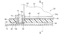
- FIG. 2 is a schematic sectional view taken along line II-II in FIG. 1.
- FIG. 3 is a schematic sectional view taken along line III-III in FIG. 2.
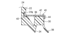
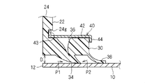
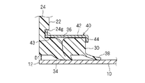
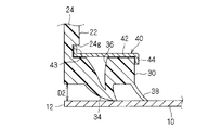
- FIG. 3 is a schematic sectional view taken along line III-III in FIG. 2. It is sectional drawing which shows the compression deformation state of a bowl-shaped part and a seal part. It is sectional drawing which shows the other compression deformation state of a bowl-shaped part and a seal part.
- FIG. 1 is a schematic perspective view showing a state in which the grommet 20 according to the embodiment is attached to the attachment plate 10
- FIG. 2 is a cross-sectional view taken along line II-II in FIG. 1, and FIGS. It is sectional drawing in the III-III line.
- 3 shows a state before the grommet 20 is attached
- FIG. 4 shows a state where the grommet is attached.
- the grommet 20 is attached to the mounting plate 10 having the through hole 12.
- the mounting plate 10 is a plate member that partitions the vehicle body, for example, the interior and exterior of the vehicle, and is formed of metal or the like.
- a through hole 12 is formed in the mounting plate 10.
- the through hole 12 has a square shape, but may have other shapes such as a circular shape.
- a wire harness 18 is inserted into the through hole 12.
- the wire harness 18 is, for example, a wiring member that electrically connects a transmission controller provided in a vehicle interior to a transmission provided outside the vehicle interior (engine room), and has at least one electric wire. Yes.
- a plurality of stud bolts 14 are erected on one main surface of the mounting plate 10 at intervals around the through hole 12. Here, stud bolts 14 are erected at positions outside the respective apexes of the rectangular through hole 12.
- the stud bolt 14 has a threaded portion 14a having a thread groove formed on the outer periphery and a disc-shaped head 14b provided at one end of the threaded portion 14a.
- the head 14b is attached to the mounting plate 10. Is fixed to the mounting plate 10 by welding or the like in a state of being in contact with one main surface.
- the grommet 20 is attached to the through hole 12 in a state where the wire harness 18 is inserted and fixed to the grommet 20, thereby protecting the wire harness 18 and suppressing water intrusion in the through hole (that is, waterproofing). have.
- the grommet 20 includes a grommet main body 22 and a pressing member 40.
- the grommet main body 22 is formed of an elastic material such as an elastomer (rubber or the like), and includes a wire harness insertion portion 24 and a hook-shaped portion 30.
- the wire harness insertion part 24 is formed so that the wire harness 18 can be inserted, and has an extent that can close the through hole 12. More specifically, the wire harness insertion part 24 is formed in a box shape having an opening corresponding to the through hole 12, here, a rectangular parallelepiped box shape having a rectangular opening corresponding to the through hole 12. Moreover, the cylinder part 25 which can insert the wire harness 18 is formed in the surface facing the said opening among the wire harness insertion parts 24. As shown in FIG. The wire harness 18 is disposed through the through-hole 12 by being inserted through the main cylinder portion 25. Further, the wire harness 18 is preferably fixed at a fixed position in the main cylinder portion 25. Moreover, it is preferable that the cylinder part 25 is clamp
- the hook-shaped portion 30 is provided on the outer periphery of the wire harness insertion portion 24, and is configured to be able to come into contact with one main surface of the mounting plate 10 on the outer periphery of the through hole 12.
- the hook-shaped part 30 is provided on the outer periphery of the substantially rectangular opening of the wire harness insertion part 24.
- the bowl-shaped part 30 is formed in the bowl-shaped part of substantially constant thickness.
- a bolt through hole 32 is formed at a position corresponding to the stud bolt 14 (here, an outer position corresponding to each vertex of the through hole 12) in the bowl-shaped portion 30 (see FIG. 2).
- a portion of the hook-shaped portion 30 that faces the one main surface of the mounting plate 10 is formed as a substantially flat surface, and a seal portion 34 that extends along the extending direction of the hook-shaped portion 30 is formed on the surface. Yes.
- the seal portion 34 is formed on the outer periphery of the through hole 12 so as to avoid the stud bolt 14 and form a substantially square ring.
- the seal part 34 is formed in a ridge shape in which a cross-sectional shape in a direction perpendicular to the extending direction is a triangular shape. That is, the outer peripheral surface of the seal portion 34 has a triangular cross section. Further, in the triangular shape of the cross section exhibited by the outer peripheral surface of the seal portion 34, the outer side is set shorter than the inner side. In other words, the apex of the seal portion 34 is provided at a position that is biased toward the outer peripheral side of the hook-shaped portion 30 with respect to the center in the width direction of the seal portion 34.
- a portion of the flange-shaped portion 30 that is opposite to the surface facing the one main surface of the mounting plate 10 is also formed in a substantially flat surface, and the concave portion is located on the back of the seal portion 34 on this surface. 36 is formed.
- the concave portion 36 is formed in a groove shape having a triangular cross section corresponding to the outer peripheral surface shape of the seal portion 34.
- the outer side is set to be shorter than the inner side in the triangular cross-section formed by the inner peripheral surface of the concave portion 36, and the deepest vertex portion of the concave portion 36 is the concave portion.
- the apex portion of the seal portion 34 is provided at a position on the outer peripheral side of the bowl-shaped portion 30 with respect to the deepest apex portion of the recess 36. It is preferable that the deepest apex portion of the recess 36 has a depth that reaches the inside of the seal portion 34 beyond the surface of the hook-shaped portion 30 that faces the one main surface of the mounting plate 10. Not required.
- a skirt-like auxiliary seal portion 38 is provided on the outer peripheral edge portion of the flange-shaped portion 30 that faces the one main surface of the mounting plate 10.
- the auxiliary seal portion 38 is pressed against one main surface of the mounting plate 10 on the outer peripheral side of the seal portion 34.
- the pressing member 40 is a member formed of a material having higher rigidity than the grommet main body 22, for example, a metal.
- the pressing member 40 is provided on the opposite side of the portion of the hook-shaped portion 30 that faces the one main surface of the mounting plate 10, and is configured to be fixed to the mounting plate 10. The pressing member 40 is pressed against the one main surface of the mounting plate 10 in a state where the pressing member 40 is fixed to the mounting plate 10.
- the pressing member 40 is a member that is locked by punching and bending a metal plate, and is formed in a frame shape corresponding to the bowl-shaped portion 30 as a whole. More specifically, the pressing member 40 includes a rectangular plate frame-shaped pressing main plate portion 42 that presses the back surface of the hook-shaped portion 30, and the wire harness insertion portion 24 of the grommet main body 22 from the inner peripheral edge portion of the pressing main plate portion 42. It has an inner edge 43 that extends along the outer peripheral portion, and an outer peripheral edge 44 that extends from the outer peripheral edge of the pressing main plate portion 42 along the outer peripheral portion of the bowl-shaped portion 30.
- the inner edge 43 is fitted into the groove 24g of the wire harness insertion portion 24 and the outer peripheral edge 44 is the outer periphery of the hook 30 with the pressing main plate 42 disposed on the back side of the hook 30.
- the pressing member 40 is attached to the grommet body 22 by being externally fitted to the portion.
- annular boss 45 is protruded from the pressing member 40 at a position corresponding to each stud bolt 14 (the bolt through hole 32 of the bowl-shaped portion 30).
- the bosses 45 project from the four corners of the pressing member 40.
- the boss portion 45 is disposed in the bolt through hole 32 of the bowl-shaped portion 30.
- the stud bolt 14 is inserted into the boss portion 45, and the tip end portion of the stud bolt 14 is protruded from the hook-like portion 30 and the pressing member 40.
- the nut 16 is screwed and fastened to the stud bolt 14
- the flange portion 30 is pushed toward the mounting plate 10 on the outer peripheral side of the through hole 12, and the seal portion 34 and the auxiliary seal portion 38 are the main parts of the mounting plate 10. Pressed against the surface.
- the apex of the seal portion 34 When the seal portion 34 is pressed against one main surface of the mounting plate 10, the apex of the seal portion 34 is provided at a position that is biased toward the outer peripheral side of the flange portion 30 rather than the center in the width direction of the seal portion 34.
- the seal portion 34 is compressed and deformed so that the apex of the seal portion 34 falls to the outer peripheral side (see FIG. 4).
- the concave portion 36 is also formed in a groove shape having a triangular cross section corresponding to the outer peripheral surface shape of the seal portion 34, the seal portion 34 can be more reliably positioned on the outer peripheral side so that the apex of the seal portion 34 is positioned on the outer peripheral side. Compressive deformation.
- the flange portion 30 and the seal portion 34 are compressed and deformed between the pressing member 40 and the mounting plate 10 so as to fill the concave portion 36.
- the height of the head 14 b may vary due to the difference in the welding condition of the stud bolt 14 with respect to the mounting plate 10, or the mounting plate 10, the pressing member 40, and the grommet main body 22 may be slightly distorted.
- the distance between the mounting plate 10 and the pressing member 40 may vary.
- the distance between the mounting plate 10 and the pressing member 40 is a predetermined distance D assumed in design.
- the seal portion 34 is pressed against the mounting plate 10, and the hook-shaped portion 30 and the seal portion 34 are compressed and deformed so as to fill the recess 36 to some extent.
- the deformation amount of the seal portion 34 is as shown in FIG. Become bigger.
- the hook-shaped portion 30 and the seal portion 34 are compressed and deformed so as to fill the concave portion 36.
- the hook-shaped part 30 and the seal part 34 can compress-deform relatively easily, and the reaction force of the hook-shaped part 30 and the seal part 34 after a compression deformation is small.
- the reaction force of the hook-shaped portion 30 and the seal portion 34 becomes difficult to deform the pressing member 40, and the pressing member 40 can press the hook-shaped portion 30 with a sufficient force on the entire outer periphery, thereby improving the sealing performance. Can be good. Further, the situation where the stud bolt 14 falls off the mounting plate 10 due to the reaction force of the seal portion 34 is also suppressed.
- the deformation amount of the seal portion 34 becomes smaller as shown in FIG.
- the seal portion 34 is pressed against one main surface of the mounting plate 10. For this reason, even in this case, the sealing property can be improved.
- the hook-shaped portion 30 and the seal portion 34 are compressed so as to fill the concave portion 36. Deform. For this reason, even if the seal portion 34 is largely compressed and deformed, the reaction force caused by the compression portion 34 is small. For this reason, the deformation of the pressing member 40 is suppressed, and the state in which the pressing member 40 presses the entire outer periphery of the hook-shaped portion 30 and the seal portion 34 is brought into contact with one main surface of the mounting plate 10 is more reliably maintained. Thereby, the sealing performance of the grommet 20 can be improved.
- the seal portion 34 can be easily deformed compared with the case where the concave portion 36 is not provided, and the tightening load of the nut 16 can be increased. Can be reduced.
- the concave portion 36 is formed on the back portion of the bowl-shaped portion 30, the weight of the grommet 20 can be reduced.
- the outer peripheral surface of the seal portion 34 has a triangular shape in cross section and the apex thereof is provided so as to be biased toward the outer peripheral side of the hook-shaped portion 30, when the hook-shaped portion 30 is pressed against the mounting plate 10,
- the seal portion 34 is compressed in a state where the apex of the seal portion 34 is disposed on the outer peripheral side of the bowl-shaped portion 30.
- the seal portion 34 compressed and deformed in this way enters water from the outer peripheral side of the bowl-shaped portion 30 (see arrow P2) rather than water from the inner circumference side of the bowl-shaped portion 30 (see arrow P1). ) Is more waterproof. Therefore, it is possible to improve the waterproof sealing property against water intrusion from the outside of the grommet 20 between the grommet main body 22 and the mounting plate 10.
- the apex of the entire seal portion 34 extends toward the outer periphery of the flange 30, the apex is disposed on the outer periphery of the flange 34 in the entire extending direction of the seal 34. In the installed state, the seal portion 34 is compressed and deformed. Here, if the apex of the seal portion 34 is disposed on the outer peripheral side of the hook-shaped portion 30 or the inner peripheral side, the apex of the seal portion 34 is set on the outer peripheral side and the inner peripheral side of the hook-shaped portion 30. In the portion that is switched between, the adhesiveness between the seal portion 34 and the mounting plate 10 is deteriorated, and a portion inferior in sealability is generated.
- the seal portion 34 is compressed and deformed in a state where the apex of the seal portion 34 extends in the whole extending direction of the seal portion 34 toward the outer peripheral side of the flange portion 30, Good sealability can be obtained in the entire extending direction of the portion 30 and the seal portion 34.
- the concave portion 36 is also formed in a groove shape having a triangular cross section corresponding to the outer peripheral surface shape of the seal portion 34, when the seal portion 34 is compressed, the apex of the seal portion 34 is more surely bowl-shaped. It is disposed on the outer peripheral side of the portion 30. For this reason, the seal part 34 is more excellent.
- the seal portion 34 has the above-described shape, and it may be a ridge shape having a semicircular cross section or a square cross section.
- the shape of the recessed part 36 is not limited to the shape demonstrated in the said embodiment, A cross-sectional semicircle groove
- the recessed part may be provided partially with respect to the extending direction of the seal part 34.
- the opening shape of the grommet body 22 and the pressing member 40 do not need to be rectangular, and may be circular or the like according to the shape of the through hole 12.
Landscapes
- Engineering & Computer Science (AREA)
- Architecture (AREA)
- Civil Engineering (AREA)
- Structural Engineering (AREA)
- Mechanical Engineering (AREA)
- Installation Of Indoor Wiring (AREA)
- Insulating Bodies (AREA)
- Gasket Seals (AREA)
Abstract
Description
Claims (3)
- ワイヤーハーネス挿通用の貫通孔を有する取付板に装着されるグロメットであって、
弾性材料によって形成され、前記ワイヤーハーネスが挿通されるワイヤーハーネス挿通部と、前記ワイヤーハーネス挿通部の外周に設けられ、前記貫通孔の外周で前記取付板の一主面に可能な鍔状部とを有するグロメット本体と、
前記鍔状部のうち前記取付板の前記一主面に対向する部分の反対側に設けられると共に、前記取付板に取付固定可能に形成され、前記取付板に取付固定された状態で前記鍔状部を前記取付板の前記一主面に押付ける押付部材と、
を備え、
前記鍔状部のうち前記取付板の前記一主面に対向する部分に前記鍔状部の延在方向に沿って延びるシール部が形成されると共に、前記鍔状部のうち前記シール部の背部に凹部が形成されている、グロメット。 - 請求項1記載のグロメットであって、
前記シール部の外周面が、横断面三角形状を呈し、その頂点が前記鍔状部の外周側に偏って設けられている、グロメット。 - 請求項2記載のグロメットであって、
前記凹部は、前記シール部の外周面形状に対応する横断面三角形状の溝形状に形成され
ている、グロメット。
Priority Applications (5)
| Application Number | Priority Date | Filing Date | Title |
|---|---|---|---|
| KR1020137028158A KR101599116B1 (ko) | 2011-05-26 | 2011-10-14 | 그로밋 |
| EP11866241.0A EP2717400A4 (en) | 2011-05-26 | 2011-10-14 | EYELET |
| US14/009,361 US20140021688A1 (en) | 2011-05-26 | 2011-10-14 | Grommet |
| CN201180071148.9A CN103597683B (zh) | 2011-05-26 | 2011-10-14 | 密封圈 |
| AU2011369095A AU2011369095B9 (en) | 2011-05-26 | 2011-10-14 | Grommet |
Applications Claiming Priority (2)
| Application Number | Priority Date | Filing Date | Title |
|---|---|---|---|
| JP2011-117815 | 2011-05-26 | ||
| JP2011117815A JP5736963B2 (ja) | 2011-05-26 | 2011-05-26 | グロメット |
Publications (1)
| Publication Number | Publication Date |
|---|---|
| WO2012160723A1 true WO2012160723A1 (ja) | 2012-11-29 |
Family
ID=47216820
Family Applications (1)
| Application Number | Title | Priority Date | Filing Date |
|---|---|---|---|
| PCT/JP2011/073677 Ceased WO2012160723A1 (ja) | 2011-05-26 | 2011-10-14 | グロメット |
Country Status (7)
| Country | Link |
|---|---|
| US (1) | US20140021688A1 (ja) |
| EP (1) | EP2717400A4 (ja) |
| JP (1) | JP5736963B2 (ja) |
| KR (1) | KR101599116B1 (ja) |
| CN (1) | CN103597683B (ja) |
| AU (1) | AU2011369095B9 (ja) |
| WO (1) | WO2012160723A1 (ja) |
Cited By (2)
| Publication number | Priority date | Publication date | Assignee | Title |
|---|---|---|---|---|
| JP2018063879A (ja) * | 2016-10-13 | 2018-04-19 | 本田技研工業株式会社 | 燃料電池スタック |
| US20220239082A1 (en) * | 2021-01-28 | 2022-07-28 | Tyler Uebelhoer | Electrical junction box for installation on metal roofs to accommodate internal wiring of solar panels |
Families Citing this family (14)
| Publication number | Priority date | Publication date | Assignee | Title |
|---|---|---|---|---|
| CA2851442C (en) | 2013-05-07 | 2021-05-25 | Gabe Coscarella | Backplate for a utility box |
| DE102014214553A1 (de) * | 2013-08-06 | 2015-02-12 | Schaeffler Technologies Gmbh & Co. Kg | Deckelbaugruppe für einen Drehmomentwandler, die eine Antriebsplatte mit einem elastischen Vorspannungselement aufweist |
| US9109359B1 (en) * | 2014-02-03 | 2015-08-18 | Gabe Coscarella | Weather barrier for a building penetration |
| US10018287B2 (en) | 2014-02-28 | 2018-07-10 | Gabe Coscarella | Weather barrier for a building penetration |
| CN106558377A (zh) * | 2015-09-30 | 2017-04-05 | 明光市奇美橡塑有限公司 | 一种绝缘橡胶垫圈 |
| CA2973567C (en) | 2017-07-17 | 2026-03-17 | Gabe Coscarella | Weather barrier for a building penetration with a removable collar |
| JP6970064B2 (ja) | 2018-08-30 | 2021-11-24 | 矢崎総業株式会社 | グロメット |
| US12081005B2 (en) | 2018-12-07 | 2024-09-03 | Gabe Coscarella | Weatherproof enclosure for junction box |
| JP7110258B2 (ja) * | 2020-02-18 | 2022-08-01 | 矢崎総業株式会社 | グロメット、及び、ワイヤハーネス |
| CA3124917A1 (en) | 2020-07-17 | 2022-01-17 | Gabe Coscarella | Support for sealing around a building penetration |
| CN112103870A (zh) * | 2020-09-14 | 2020-12-18 | 宁波诗兰姆汽车零部件有限公司 | 管套 |
| JP7216690B2 (ja) * | 2020-09-24 | 2023-02-01 | 矢崎総業株式会社 | グロメット、及び、ワイヤハーネス |
| JP7581771B2 (ja) * | 2020-10-28 | 2024-11-13 | 住友電装株式会社 | グロメット |
| KR102692794B1 (ko) * | 2022-03-15 | 2024-08-07 | 주식회사 경신 | 차량용 대쉬 그로멧 |
Citations (3)
| Publication number | Priority date | Publication date | Assignee | Title |
|---|---|---|---|---|
| JPH08336224A (ja) * | 1995-06-06 | 1996-12-17 | Yazaki Corp | グロメット |
| JPH10294028A (ja) * | 1997-04-21 | 1998-11-04 | Yazaki Corp | 押え板付きグロメット |
| JP2000085395A (ja) | 1998-09-16 | 2000-03-28 | Toyota Motor Corp | ボディパネルの変速機コントロールケーブル貫通構造 |
Family Cites Families (19)
| Publication number | Priority date | Publication date | Assignee | Title |
|---|---|---|---|---|
| NO140752C (no) * | 1977-08-29 | 1979-11-07 | Rieber & Son As | Kombinert forme- og tetningselement til bruk i en muffeende i termoplastroer |
| FR2547888B1 (fr) * | 1983-06-22 | 1985-12-13 | Sabla Sa | Bague d'etancheite a implants pour tuyaux a emboitement |
| US4602125A (en) * | 1985-05-10 | 1986-07-22 | The Bergquist Company | Mounting pad with tubular projections for solid-state devices |
| US5138117A (en) * | 1987-07-09 | 1992-08-11 | Yazaki Corporation | Watertight sealing lip for grommet |
| US5454573A (en) * | 1993-11-01 | 1995-10-03 | Vernay Laboratories, Inc. | Damper |
| JP3002941B2 (ja) * | 1994-03-10 | 2000-01-24 | 矢崎総業株式会社 | グロメット |
| US6119305A (en) * | 1997-06-17 | 2000-09-19 | Ta Mfg Co. | Sealing elements |
| US6088876A (en) * | 1998-09-30 | 2000-07-18 | Lucent Technologies, Inc. | Sealing grommet |
| JP3417324B2 (ja) * | 1999-01-14 | 2003-06-16 | 住友電装株式会社 | ワイヤハーネスのグロメット装着部の防水構造および防水方法 |
| US6299176B1 (en) * | 1999-03-03 | 2001-10-09 | S&B Technical Products | Dual purpose low insertion force gasket |
| JP3943858B2 (ja) * | 2001-04-27 | 2007-07-11 | 矢崎総業株式会社 | グロメット |
| JP2003164041A (ja) | 2001-11-27 | 2003-06-06 | Fujikura Ltd | グロメットの取り付け構造 |
| US6691331B2 (en) * | 2002-01-07 | 2004-02-17 | Bakup, Llc | Toilet gasket |
| SE527822C2 (sv) * | 2004-09-23 | 2006-06-13 | G A Gold Seal Dev Ltd C O Kpmg | Tätningssystem för förband |
| US7509724B2 (en) * | 2004-12-07 | 2009-03-31 | S & B Technical Products, Inc. | Snap fit sealing gasket with precisely located internal retainer ring for square pipe grooves |
| JP4783141B2 (ja) * | 2005-12-26 | 2011-09-28 | 矢崎総業株式会社 | 防水グロメット |
| US7891709B2 (en) * | 2006-09-06 | 2011-02-22 | Lg Electronics Inc. | Sealing member for exhaust pipe of dryer |
| US7723622B2 (en) * | 2007-05-22 | 2010-05-25 | Panduit Corp. | Sealing assembly |
| JP5633353B2 (ja) * | 2010-12-10 | 2014-12-03 | 住友電装株式会社 | グロメット |
-
2011
- 2011-05-26 JP JP2011117815A patent/JP5736963B2/ja not_active Expired - Fee Related
- 2011-10-14 US US14/009,361 patent/US20140021688A1/en not_active Abandoned
- 2011-10-14 EP EP11866241.0A patent/EP2717400A4/en not_active Withdrawn
- 2011-10-14 CN CN201180071148.9A patent/CN103597683B/zh not_active Expired - Fee Related
- 2011-10-14 KR KR1020137028158A patent/KR101599116B1/ko not_active Expired - Fee Related
- 2011-10-14 AU AU2011369095A patent/AU2011369095B9/en not_active Ceased
- 2011-10-14 WO PCT/JP2011/073677 patent/WO2012160723A1/ja not_active Ceased
Patent Citations (3)
| Publication number | Priority date | Publication date | Assignee | Title |
|---|---|---|---|---|
| JPH08336224A (ja) * | 1995-06-06 | 1996-12-17 | Yazaki Corp | グロメット |
| JPH10294028A (ja) * | 1997-04-21 | 1998-11-04 | Yazaki Corp | 押え板付きグロメット |
| JP2000085395A (ja) | 1998-09-16 | 2000-03-28 | Toyota Motor Corp | ボディパネルの変速機コントロールケーブル貫通構造 |
Non-Patent Citations (1)
| Title |
|---|
| See also references of EP2717400A4 |
Cited By (3)
| Publication number | Priority date | Publication date | Assignee | Title |
|---|---|---|---|---|
| JP2018063879A (ja) * | 2016-10-13 | 2018-04-19 | 本田技研工業株式会社 | 燃料電池スタック |
| US20220239082A1 (en) * | 2021-01-28 | 2022-07-28 | Tyler Uebelhoer | Electrical junction box for installation on metal roofs to accommodate internal wiring of solar panels |
| US11757269B2 (en) * | 2021-01-28 | 2023-09-12 | Tyler Uebelhoer | Electrical junction box for installation on metal roofs to accommodate internal wiring of solar panels |
Also Published As
| Publication number | Publication date |
|---|---|
| EP2717400A1 (en) | 2014-04-09 |
| EP2717400A4 (en) | 2015-09-16 |
| AU2011369095B2 (en) | 2015-06-18 |
| CN103597683B (zh) | 2016-08-17 |
| JP2012249378A (ja) | 2012-12-13 |
| KR20140001247A (ko) | 2014-01-06 |
| US20140021688A1 (en) | 2014-01-23 |
| CN103597683A (zh) | 2014-02-19 |
| JP5736963B2 (ja) | 2015-06-17 |
| KR101599116B1 (ko) | 2016-03-02 |
| AU2011369095A1 (en) | 2013-12-19 |
| AU2011369095B9 (en) | 2015-07-02 |
Similar Documents
| Publication | Publication Date | Title |
|---|---|---|
| JP5736963B2 (ja) | グロメット | |
| US9464734B2 (en) | Cord-like member holder for working machine | |
| US10084199B2 (en) | Fuel cell stack enclosure | |
| US9726290B2 (en) | Seal structure using metal gasket | |
| JP2017027701A (ja) | 電池パックのシール構造 | |
| EP3923366A1 (en) | Seal structure | |
| US20210367296A1 (en) | Seal structure | |
| WO2014061122A1 (ja) | シールワッシャ付きナット | |
| JP5464069B2 (ja) | グロメットの車体取付構造 | |
| JP5410120B2 (ja) | 覗き窓 | |
| JP2000085395A (ja) | ボディパネルの変速機コントロールケーブル貫通構造 | |
| CN109428295B (zh) | 线缆填料函 | |
| US9970546B2 (en) | Seal structure and seal method | |
| CN206351880U (zh) | 盖组件及集装箱的组件 | |
| JP2015202697A (ja) | 電気デバイス収容体 | |
| JP2018131075A (ja) | 車両用ルーフアンテナ取付装置 | |
| JP2020158004A (ja) | ルーフレール | |
| CN104806823A (zh) | 密封圈 | |
| CN222372870U (zh) | 用于车辆的车身组件和车辆 | |
| US9961786B2 (en) | Method and structure for limiting cover deflection in an ECU when exposed to high altitude environments | |
| JP7248494B2 (ja) | ボックス | |
| JP6021428B2 (ja) | 密閉型電動圧縮機 | |
| JP5024091B2 (ja) | グロメット取付構造 | |
| CN103625387A (zh) | 车辆中的牌照安装构造 | |
| JP2025175537A (ja) | 端子台 |
Legal Events
| Date | Code | Title | Description |
|---|---|---|---|
| 121 | Ep: the epo has been informed by wipo that ep was designated in this application |
Ref document number: 11866241 Country of ref document: EP Kind code of ref document: A1 |
|
| WWE | Wipo information: entry into national phase |
Ref document number: 14009361 Country of ref document: US |
|
| REEP | Request for entry into the european phase |
Ref document number: 2011866241 Country of ref document: EP |
|
| WWE | Wipo information: entry into national phase |
Ref document number: 2011866241 Country of ref document: EP |
|
| ENP | Entry into the national phase |
Ref document number: 20137028158 Country of ref document: KR Kind code of ref document: A |
|
| NENP | Non-entry into the national phase |
Ref country code: DE |
|
| ENP | Entry into the national phase |
Ref document number: 2011369095 Country of ref document: AU Date of ref document: 20111014 Kind code of ref document: A |