WO2012160932A1 - 伝送装置及びその処理方法 - Google Patents
伝送装置及びその処理方法 Download PDFInfo
- Publication number
- WO2012160932A1 WO2012160932A1 PCT/JP2012/061076 JP2012061076W WO2012160932A1 WO 2012160932 A1 WO2012160932 A1 WO 2012160932A1 JP 2012061076 W JP2012061076 W JP 2012061076W WO 2012160932 A1 WO2012160932 A1 WO 2012160932A1
- Authority
- WO
- WIPO (PCT)
- Prior art keywords
- signal
- communication unit
- control board
- sdh
- packet
- Prior art date
- Legal status (The legal status is an assumption and is not a legal conclusion. Google has not performed a legal analysis and makes no representation as to the accuracy of the status listed.)
- Ceased
Links
Images


Classifications
-
- H—ELECTRICITY
- H04—ELECTRIC COMMUNICATION TECHNIQUE
- H04B—TRANSMISSION
- H04B10/00—Transmission systems employing electromagnetic waves other than radio-waves, e.g. infrared, visible or ultraviolet light, or employing corpuscular radiation, e.g. quantum communication
- H04B10/03—Arrangements for fault recovery
-
- H—ELECTRICITY
- H04—ELECTRIC COMMUNICATION TECHNIQUE
- H04B—TRANSMISSION
- H04B1/00—Details of transmission systems, not covered by a single one of groups H04B3/00 - H04B13/00; Details of transmission systems not characterised by the medium used for transmission
- H04B1/74—Details of transmission systems, not covered by a single one of groups H04B3/00 - H04B13/00; Details of transmission systems not characterised by the medium used for transmission for increasing reliability, e.g. using redundant or spare channels or apparatus
-
- H—ELECTRICITY
- H04—ELECTRIC COMMUNICATION TECHNIQUE
- H04B—TRANSMISSION
- H04B10/00—Transmission systems employing electromagnetic waves other than radio-waves, e.g. infrared, visible or ultraviolet light, or employing corpuscular radiation, e.g. quantum communication
- H04B10/80—Optical aspects relating to the use of optical transmission for specific applications, not provided for in groups H04B10/03 - H04B10/70, e.g. optical power feeding or optical transmission through water
- H04B10/801—Optical aspects relating to the use of optical transmission for specific applications, not provided for in groups H04B10/03 - H04B10/70, e.g. optical power feeding or optical transmission through water using optical interconnects, e.g. light coupled isolators, circuit board interconnections
-
- H—ELECTRICITY
- H04—ELECTRIC COMMUNICATION TECHNIQUE
- H04L—TRANSMISSION OF DIGITAL INFORMATION, e.g. TELEGRAPHIC COMMUNICATION
- H04L12/00—Data switching networks
- H04L12/64—Hybrid switching systems
- H04L12/6418—Hybrid transport
-
- H—ELECTRICITY
- H04—ELECTRIC COMMUNICATION TECHNIQUE
- H04Q—SELECTING
- H04Q11/00—Selecting arrangements for multiplex systems
- H04Q11/04—Selecting arrangements for multiplex systems for time-division multiplexing
-
- H—ELECTRICITY
- H04—ELECTRIC COMMUNICATION TECHNIQUE
- H04J—MULTIPLEX COMMUNICATION
- H04J2203/00—Aspects of optical multiplex systems other than those covered by H04J14/05 and H04J14/07
- H04J2203/0001—Provisions for broadband connections in integrated services digital network using frames of the Optical Transport Network [OTN] or using synchronous transfer mode [STM], e.g. SONET, SDH
- H04J2203/0003—Switching fabrics, e.g. transport network, control network
- H04J2203/0026—Physical details
-
- H—ELECTRICITY
- H04—ELECTRIC COMMUNICATION TECHNIQUE
- H04J—MULTIPLEX COMMUNICATION
- H04J3/00—Time-division multiplex systems
- H04J3/16—Time-division multiplex systems in which the time allocation to individual channels within a transmission cycle is variable, e.g. to accommodate varying complexity of signals, to vary number of channels transmitted
- H04J3/1605—Fixed allocated frame structures
- H04J3/1611—Synchronous digital hierarchy [SDH] or SONET
-
- H—ELECTRICITY
- H04—ELECTRIC COMMUNICATION TECHNIQUE
- H04J—MULTIPLEX COMMUNICATION
- H04J3/00—Time-division multiplex systems
- H04J3/16—Time-division multiplex systems in which the time allocation to individual channels within a transmission cycle is variable, e.g. to accommodate varying complexity of signals, to vary number of channels transmitted
- H04J3/1605—Fixed allocated frame structures
- H04J3/1623—Plesiochronous digital hierarchy [PDH]
-
- H—ELECTRICITY
- H04—ELECTRIC COMMUNICATION TECHNIQUE
- H04Q—SELECTING
- H04Q2213/00—Indexing scheme relating to selecting arrangements in general and for multiplex systems
- H04Q2213/13098—Mobile subscriber
Definitions
- the present invention relates to a transmission apparatus that relays communication signals and a processing method thereof.
- This application claims priority based on Japanese Patent Application No. 2011-113222 for which it applied on May 20, 2011, and uses the content here.
- wireless transmission characteristics are communication by spatial propagation, transmission performance may vary depending on environmental conditions such as weather and obstacles. Therefore, in the case of wireless transmission, it is necessary to limit the transmission band when weather conditions deteriorate.
- optical transmission uses an optical fiber as a medium, there is a risk of the optical fiber being cut due to the influence of an earthquake, fire, road construction, or the like. Therefore, in the case of optical transmission, when an optical fiber is cut due to an earthquake disaster or the like, it is necessary to set up a detour route to avoid the use of the cut line and restore the optical fiber cut.
- Patent Document 1 A technique related to the present invention is disclosed in Patent Document 1.
- an object of the present invention is to provide a transmission apparatus and a processing method thereof that can solve such problems.
- the present invention includes a housing having a plurality of slots into which a substrate can be inserted and removed, At least one control board;
- a PWE (Pseudo Wire Emulation) interface communication unit connected to the control board and converting an input SDH (Synchronous Digital Hierarchy) signal or PDH (Pre Synchronous Digital Hierarchy) signal into a packet signal and outputting the packet signal;
- a wireless transmission communication unit connected to the control board and converting the packet signal into a radio signal and outputting the radio signal;
- An optical transmission communication unit connected to the control board, converting the packet signal into an optical transmission signal and outputting the optical transmission signal;
- the transmission apparatus is characterized in that each unit is provided in each of the plurality of slots.
- an SDH / PDH signal communication unit that is connected to the control board and outputs an input SDH signal or PDH signal to the control board is further provided in the slot.
- the PWE interface communication unit may receive the SDH signal or the PDH signal output via the SDH / PDH signal communication unit and the control board, convert it to the packet signal, and output the packet signal.
- the present invention also includes a housing having a plurality of slots into which a board can be inserted and removed, and at least one control board, and connected to the control board.
- a processing method of a transmission device provided with a transmission communication unit in each of the plurality of slots,
- the PWE interface communication unit converts the input SDH signal or PDH signal into a packet signal and outputs it
- the wireless transmission communication unit converts the packet signal into a wireless signal and outputs it
- an SDH / PDH signal communication unit connected to the control board and outputting the input SDH signal or PDH signal to the control board is further provided in the slot.
- the PWE interface communication unit may receive the SDH signal or the PDH signal output via the SDH / PDH signal communication unit and the control board, convert it to the packet signal, and output the packet signal.
- a transmission apparatus that holds only a packet switch in the control board is provided.
- a transmission apparatus that converts a signal for an SDH / PDH signal into a radio signal or an optical transmission signal and outputs the signal to the adapting side.
- a redundant configuration can be taken with respect to the input signal, and the output by the radio signal or the output by the optical transmission can be adaptively distributed. High communication transfer. That is, if the wireless transmission band is restricted due to environmental deterioration, it is supplemented by optical transmission. If the optical fiber is cut due to a severe disaster or the like, the transmission path can be secured by wireless transmission.
- FIG. 1 is a configuration diagram of a communication network to which a transmission device according to an embodiment of the present invention is applied. It is a schematic external view of the transmission apparatus of the embodiment. It is a figure which shows the connection structure of each component of the transmission apparatus of the embodiment. It is a 1st figure which shows the connection structure of the main signal of a control board and a communication unit. It is a 2nd figure which shows the connection structure of the main signal of a control board and a communication unit. It is a 3rd figure which shows the connection structure of the main signal of a control board and a communication unit. It is a 4th figure which shows the connection structure of the main signal of a control board and a communication unit.
- FIG. 1 is a configuration diagram of a communication network 50 to which the transmission apparatus 2 (see FIG. 2) of this embodiment is applied.
- the communication network 50 includes a wireless terminal 51 such as a mobile phone, a wireless base station 52, a wireless line control station 53, a core network 54, and an external network 55.
- the wireless terminal 51 can communicate within a range where radio waves from the wireless base station 52 reach.
- the radio base station 52 is connected to a radio channel control station 53 at a higher level, and each radio channel control station 53 controls a plurality of radio base stations 52.
- the radio network controller 53 is connected to a core network 54 that is a trunk network.
- the core network 54 is connected to an external network 55 (for example, a mobile communication network or a general public line network of another communication carrier).
- the wireless communication device 1 is a communication device that enables high-speed wireless communication by using microwaves, and indoors such as an outdoor device such as an antenna that transmits and receives radio waves and a transmission device 2 that processes received radio waves. Equipment.
- FIG. 2 is a schematic external view of the transmission apparatus 2.
- a transmission device 2 included as a function of the wireless communication device 1 includes a rectangular parallelepiped housing 3 and a plurality of communication units 4 (indicated as “I / F” in the drawing) mounted on the housing 3,
- a control board 5, a power supply unit 7, and an external device connection board 8 are provided.
- the communication unit 4, the control board 5, the power supply unit 7, and the external device connection board 8 are connected via a mother board 9 (see FIG. 3 described later) disposed on the back side facing the opening of the housing 3. Yes.
- the housing 3 has a box-shaped housing body whose front surface has an opening.
- a plurality of ventilation holes are formed on both side surfaces of the housing body 10.
- a direction perpendicular to the surface constituting the opening is referred to as a depth direction
- a horizontal direction orthogonal to the depth direction is referred to as a left-right direction.
- the internal space of the housing 3 has four regions divided into four in the left-right direction when viewed from the opening side, and is divided into six steps in the up-down direction (fifth step, 6 The steps are common parts).
- the upper four stages function as a plurality of slots into which the substrate can be inserted and removed.
- the internal space of the housing 3 may be configured so as to have an arbitrary number of divisions in the left-right direction when viewed from the opening side and an arbitrary number of divisions in the vertical direction.
- the motherboard 9 is provided with a plurality of connectors that can connect the communication unit 4, the control board 5, the power supply unit 7, and the external device connection board 8 at corresponding positions.
- the communication units 4 a to 4 b (collectively referred to as the communication unit 4), the control board 5, the fan unit 6, the power supply unit 7, and the external device connection board 8 are connected via a mother board 9. It is connected.
- the transmission apparatus 2 has two control boards 5, two power supply units 7, and two fan units 6, and a plurality of communication units 4 can be connected.
- the two power supply units 7 (indicated as “PS 1” and “PS 2” in FIG. 3) have the same configuration and are connected to the control board 5, the fan unit 6, and external devices via the motherboard 9. It is comprised so that electric power may be supplied to the board
- the power required by the transmission device 2 can be supplied by one power supply unit 7. That is, the transmission apparatus 2 is configured to be operable even when one of the two power supply units 7 is stopped (failed).
- the two power supply units 7 are set so as to operate in parallel and share the required power in normal times. On the other hand, when one of the power supply units 7 fails, the power supply unit 7 that has not failed is set to supply all the power. Further, the power supply unit 7 is configured so that the failed power supply unit 7 can be replaced without stopping the operation of the wireless communication device 1.
- the two control boards 5 (indicated as “MAIN CARD 1” and “MAIN CARD 2” in FIG. 3) also have the same configuration, and control and control each component of the transmission apparatus 2 respectively.
- a control board 5 is mounted. That is, the transmission device 2 can be operated even when one of the control boards 5 is stopped. Further, the control board 5 is configured so that the failed control board 5 can be replaced without stopping the operation of the wireless communication apparatus 1.
- the two fan units 6 (indicated as “FAN 1” and “FAN 2” in FIG. 3) also have the same configuration, each having two fans, and as described above, the housing 3 It is configured to exhaust the air inside. In normal times, two fan units 6, that is, four fans are set to operate. When one fan unit 6 fails, the remaining fan units 6 are set to increase the wind power.
- the communication unit 4 includes an SDH (Synchronous Digital Hierarchy) / PDH (Pre Synchronous Digital Hierarchy) signal communication unit 4a (in FIG. 3, "LOW I / F"), a packet signal communication unit. 4b (indicated as “LOW I / F” in FIG. 3), wireless transmission communication unit 4c (indicated as “HIGH I / F” in FIG. 3), optical transmission communication unit 4d (in FIG. 3, “HIGH I / F”) I / F ”) can be connected.
- the control board 5 can perform signal control of the SDH / PDH signal communication unit 4a, the packet signal communication unit 4b, the wireless transmission communication unit 4c, and the optical transmission communication unit 4d.
- the control board 5 can convert and transfer signals among the SDH / PDH signal communication unit 4a, the packet signal communication unit 4b, the wireless transmission communication unit 4c, and the optical transmission communication unit 4d. is there.
- the external device connection board 8 (denoted as “TERM” in FIG. 3) is a board for connecting an external device such as a personal computer and the control board 5.
- the front panel is provided with a connector for enabling communication.
- the external device connection board 8 is configured to be connectable to either of the two control boards 5.
- FIG. 4 is a first diagram illustrating a connection configuration of main signals between the control board 5 and the communication unit 4.
- a description will be given of a connection configuration of main signals of the control board 5, the SDH / PDH signal communication unit 4a, the packet signal communication unit 4b, the wireless transmission communication unit 4c, and the optical transmission communication unit 4d.
- the SDH / PDH signal communication unit 4a, the packet signal communication unit 4b, the wireless transmission communication unit 4c, and the optical transmission communication unit 4d are connected via a mother board 9 (not shown in FIG. 4).
- the control board 5 is equipped with a TDM switch 45 that performs TDM (Time Division Multiplex) data transfer processing and a packet switch 46 that performs packet communication data transfer processing.
- TDM Time Division Multiplex
- the SDH / PDH signal communication unit 4 a is connected to the TDM switch 45 of the control board 5 through the mother board 9. Note that the SDH / PDH signal communication unit 4 a may be connected to the packet switch 46 of the control board 5 via the mother board 9.
- the packet signal communication unit 4 b is connected to the packet switch 46 of the control board 5 via the mother board 9.
- the packet signal communication unit 4b may be connected to the TDM switch 45 of the control board 5 via the mother board 9.
- the wireless transmission communication unit 4 c is connected to the TDM switch 45 of the control board 5 through the mother board 9 and is connected to the packet switch 46 of the control board 5 through the mother board 9.
- the optical transmission communication unit 4 d (high-speed interface card) is also connected to the packet switch 46 of the control board 5 via the mother board 9 and also connected to the TDM switch 45 of the control board 5 via the mother board 9. .
- the TDM switch 45 of the control board 5 receives the SDH / PDH signal as the client signal, and the packet switch 46 of the control board 5 receives the packet signal (for example, Ethernet) as the client signal. (Registered trademark) signal). Then, the TDM switch 45 or the packet switch 46 of the control board 5 performs control to output the received signal to the wireless transmission communication unit 4c or to the optical transmission communication unit 4d.
- the wireless transmission communication unit 4c outputs the received signal as a wireless signal
- the optical transmission communication unit 4d outputs the received signal as an optical transmission signal.
- the TDM switch 45 when the TDM switch 45 receives the SDH / PDH signal from the SDH / PDH signal communication unit 4a, the TDM switch 45 performs route distribution in line units by switching processing. Thus, the communication signal is output to the wireless transmission communication unit 4c or the optical transmission communication unit 4d.
- the packet switch 46 receives a packet signal from the packet signal communication unit 4b, the packet switch 46 distributes the route in units of flow by switching processing. Thus, the communication signal is output to the wireless transmission communication unit 4c or the optical transmission communication unit 4d.
- the wireless transmission communication unit 4 c (modem card) includes a TDM termination 41 c that terminates a communication signal input from the TDM switch 45 and a packet termination 42 c that terminates a communication signal input from the packet switch 46.
- the wireless transmission communication unit 4c performs frame processing in each layer by terminating the input communication signal.
- the wireless transmission communication unit 4c includes a multiplex processing unit 43c that performs multiplex control of communication signals, and a radio frame conversion unit 44c that converts communication signals into radio frames.
- the optical transmission communication unit 4d (SDH interface card) includes a TDM termination 41d that terminates a communication signal input from the TDM switch 45 and a packet termination 42d that terminates a communication signal input from the packet switch 46. ing.
- the optical transmission communication unit 4d performs frame processing in each layer by terminating the input communication signal.
- the optical transmission communication unit 4d includes a multiplex processing unit 43d that performs multiplex control of communication signals, and a high-speed interface unit 44d that converts communication signals into optical transmission frames.
- the PDH / SDH signal communication unit 4a When receiving the SDH / PDH signal as the client signal, the PDH / SDH signal communication unit 4a outputs the SDH / PDH signal to the control board 5 (switch card).
- the source of the client signal is a base station device in the case of a wireless network, a circuit switch in the case of a fixed network, a transmission device provided in a user building for a dedicated line service, or a data center in the case of other communication infrastructures. Or a signal transmitted from a transmission device provided in a carrier building or the like.
- the TDM switch 45 of the control board 5 When receiving the signal, the TDM switch 45 of the control board 5 (switch card) outputs a communication signal to the wireless transmission communication unit 4c or the optical transmission communication unit 4d, which is a predetermined output destination. For example, when outputting to another communication destination device by a radio signal, the TDM switch 45 outputs a communication signal to the radio transmission communication unit 4c.
- the TDM termination 41c of the wireless transmission communication unit 4c terminates the communication signal input from the TDM switch 45.
- the multiplex processing unit 43c performs multiplex control of the communication signal.
- the radio frame conversion unit 44c converts the multiplexed communication signal into a radio frame.
- the radio frame conversion unit 44c outputs a radio frame to the radio communication processing unit, and the radio communication processing unit outputs a radio signal by radio waves via the antenna.
- the TDM switch 45 when output to another communication destination device by the optical transmission signal by the sorting process, the TDM switch 45 outputs the communication signal to the optical transmission communication unit 4d.
- the TDM termination 41d of the optical transmission communication unit 4d terminates the communication signal input from the TDM switch 45.
- the multiplex processing unit 43d performs multiplex control of the communication signal.
- the high-speed interface unit 44d converts the multiplexed communication signal into an optical transmission signal. Then, the high-speed interface unit 44d outputs an optical transmission frame to the optical communication processing unit, and the optical communication processing unit outputs an optical transmission signal.
- the packet signal communication unit 4b receives a client signal
- the packet signal communication unit 4b When receiving the packet signal as a client signal, the packet signal communication unit 4b outputs the packet signal to the control board 5 (switch card).
- the packet switch 46 of the control board 5 When receiving the signal, the packet switch 46 of the control board 5 (switch card) outputs a communication signal to the wireless transmission communication unit 4c or the optical transmission communication unit 4d, which is a predetermined output destination, by a sorting process.
- the distribution rule for each flow is performed by VLAN, MPLS header, MAC address, IP address, or the like.
- the packet switch 46 when outputting to another communication destination device by a radio signal, the packet switch 46 outputs a communication signal to the radio transmission communication unit 4c.
- the packet termination 42c of the wireless transmission communication unit 4c terminates the communication signal input from the packet switch 46. Then, the multiplex processing unit 43c performs multiplex control of the communication signal.
- the radio frame conversion unit 44c converts the multiplexed communication signal into a radio frame. Then, the radio frame conversion unit 44c outputs a radio frame to the radio communication processing unit, and the radio communication processing unit outputs a radio signal via the antenna.
- the packet switch 46 when output to another communication destination device by the optical transmission signal by the distribution process, the packet switch 46 outputs the communication signal to the optical transmission communication unit 4d.
- the packet termination 42d of the optical transmission communication unit 4d terminates the communication signal input from the TDM switch 45.
- the multiplex processing unit 43d performs multiplex control of the communication signal.
- the high-speed interface unit 44d converts the multiplexed communication signal into an optical transmission signal.
- the high-speed interface unit 44d outputs an optical transmission frame to the optical communication processing unit, and the optical communication processing unit outputs an optical transmission signal.
- the direction in which the client signal is multiplexed on the wireless transmission path and the optical transmission path has been described above. However, the reverse processing is performed on the wireless transmission path and the separation direction from the optical transmission path to the client signal.
- FIG. 5 is a second diagram illustrating a connection configuration of signals between the control board and the communication unit.
- the connection configuration shown in FIG. 5 shows an example in which an SDH interface card is used as the optical transmission communication unit 4d.
- the SDH interface card is a specific example of a high-speed interface card, and its functional block is the same as the functional block of the optical transmission communication unit 4d shown in FIG.
- the signal received from the TDM switch 45 is terminated at the TDM termination 41d, and the signal received from the packet switch 46 is converted into a packet termination and an SDH frame at the packet termination unit 42d.
- frame processing in each layer is performed.
- GFP or VCAT technology is used.
- the multiplex processing unit 43d performs multiplexing control of the communication signal
- the high speed interface unit 44d outputs the optical transmission frame to the optical transmission processing unit
- the optical transmission processing unit outputs the optical transmission signal.
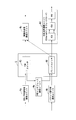
- FIG. 6 is a third diagram illustrating a connection configuration of signals between the control board and the communication unit.
- a PWE (Pseudo Wire Emulation) interface communication unit 4e is provided instead of the SDH / PDH signal communication unit 4a shown in FIG.
- the PWE interface communication unit 4e has a function of converting an SDH / PDH signal into a packet signal using pseudo-wire technology.
- 6 shows an example in which an Ethernet (registered trademark) interface card is used as the optical transmission communication unit 4d shown in FIG. 6 does not include the TDM termination 41c, and the optical transmission communication unit 4d illustrated in FIG. 6 does not include the TDM termination 41d.
- an Ethernet registered trademark
- the signal received from the packet switch 46 is terminated at the packet termination 42d, and the multiplexing processing unit 43d performs multiplexing control of the communication signal, and the high-speed interface unit 44d outputs an optical transmission frame to the optical transmission processing unit, and the optical transmission processing unit outputs an optical transmission signal.
- the wireless transmission communication unit 4c when the packet signal output from the PWE interface communication unit 4e is input via the packet switch 46, the packet terminal 42c ends the packet signal. Then, the multiplex processing unit 43c performs multiplex control of the communication signal. Also, the radio frame conversion unit 44c converts the multiplexed communication signal into a radio frame. Then, the radio frame conversion unit 44c outputs a radio frame to the radio communication processing unit, and the radio communication processing unit outputs a radio signal by radio waves via the antenna.
- FIG. 7 is a fourth diagram illustrating a connection configuration of signals between the control board and the communication unit.
- the connection configuration of the control board and the communication unit shown in this figure is such that a PWE interface communication unit 4e is separately provided as a communication unit 4 in the slot of the transmission apparatus 2 in addition to the configuration of FIG.
- the TDM switch 45 determines to output a communication signal to the optical transmission communication unit 4d by the distribution process
- the signal is output to the external PWE interface communication unit 4e.
- the PWE interface communication unit 4 e is connected to the packet switch 46. Therefore, the PWE interface communication unit 4 e converts the SDH / PDH signal into a packet signal and outputs it to the packet switch 46 of the control board 5.
- the packet switch 46 outputs the signal converted into the packet communication signal to the optical transmission communication unit 4d.
- 7 shows an example in which an Ethernet (registered trademark) interface card is used as the optical transmission communication unit 4d shown in FIG.
- the signal input from the packet switch 46 is terminated at the packet termination 42d, and the multiplex processing unit 43d performs multiplexing control of the communication signal, thereby performing high-speed processing.
- the interface unit 44d outputs an optical transmission frame to the optical transmission processing unit, and the optical transmission processing unit outputs an optical transmission signal.
- the transmission apparatus 2 has the configuration as shown in FIG. 6 or FIG. 7, a communication unit for converting an SDH / PDH signal based on Pseudo-Wire technology into a packet signal is inserted into the slot of the transmission apparatus 2, thereby In contrast to the transmission apparatus 2 that holds only the packet switch, it is possible to provide the transmission apparatus 2 that converts the SDH / PDH signal into a radio signal or an optical transmission signal and outputs it to the adapting side.
- the TDM switch 45 when it is determined that the TDM switch 45 outputs a communication signal to the wireless transmission communication unit 4c by the sorting process, the TDM switch 45 outputs a communication signal to the wireless transmission communication unit 4c.
- the TDM termination 41c of the wireless transmission communication unit 4c terminates the communication signal input from the TDM switch 45.
- the multiplex processing unit 43c performs multiplexing control of the communication signal, and the radio frame conversion unit 44c converts the multiplexed communication signal into a radio frame.
- the radio frame conversion unit 44c outputs a radio frame to the radio communication processing unit, and the radio communication processing unit outputs a radio signal by radio waves via the antenna.
- the transmission cable to which the wireless transmission communication unit 4c and the optical transmission communication unit 4d are respectively connected to the control board 5 has an E1 signal (a signal in the European hierarchical standard) input from an interface connected to the client. ) And Ethernet (registered trademark) signals constitute a specific identical frame and are multiplexed.
- the control board 5 then transmits a specific E1 channel (Ch) or a specific Ethernet included in a wireless signal or an optical transmission signal transmitted / received between the wireless transmission communication unit 4c and the optical transmission communication unit 4d with a communication partner. It detects whether or not an error has occurred in the (registered trademark) signal.
- the control board 5 generates an error only for the E1 channel (Ch) in which an error has occurred for the E1 signal included in the radio signal or the optical transmission signal, and for an Ethernet signal included in the radio signal or the optical transmission signal. Only the frame is switched from one of the radio signal and the optical transmission signal in which the error has occurred (for example, a radio signal) to the other normal signal (for example, an optical signal) and transmitted.
- the above transmission apparatus has a computer system inside.
- Each process described above is stored in a computer-readable recording medium in the form of a program, and the above process is performed by the computer reading and executing the program.
- the computer-readable recording medium means a magnetic disk, a magneto-optical disk, a CD-ROM, a DVD-ROM, a semiconductor memory, or the like.
- the program may be for realizing a part of the functions described above. Furthermore, what can implement
- the present invention by inserting a communication unit for converting an SDH / PDH signal by Pseudo-Wire technology into a packet signal into a slot of the transmission apparatus, a transmission apparatus that holds only a packet switch in the control board is provided.
- the signal for the SDH / PDH signal can be converted into a radio signal or an optical transmission signal and output to the adapting side.
- a redundant configuration is adopted for the input signal, and the output by radio signal or the output by optical transmission can be adaptively distributed. can do.
Landscapes
- Engineering & Computer Science (AREA)
- Computer Networks & Wireless Communication (AREA)
- Signal Processing (AREA)
- Physics & Mathematics (AREA)
- Electromagnetism (AREA)
- Data Exchanges In Wide-Area Networks (AREA)
- Mobile Radio Communication Systems (AREA)
- Communication Control (AREA)
- Time-Division Multiplex Systems (AREA)
Abstract
Description
本願は、2011年5月20日に出願された特願2011-113222号に基づき優先権を主張し、その内容をここに援用する。
一方で、光伝送は媒体として光ファイバを使用するため、地震、火災、道路工事等の影響により、光ファイバが切断されるリスクがある。したがって、光伝送の場合は、震災等で光ファイバが切断されると迂回ルートを設定して切断された回線の使用を避け、光ファイバ切断を復旧させることが必要となる。
なお、本願発明に関連する技術が特許文献1に開示されている。
そこでこの発明は、このような課題を解決することのできる伝送装置及びその処理方法を提供することを目的としている。
少なくとも1つの制御基板と、
前記制御基板と接続され、入力されたSDH(Synchronous Digital Hierarchy)信号またはPDH(Pre Synchronous Digital Hierarchy)信号をパケット信号へ変換して前記制御基板へ出力するPWE(Pseudo Wire Emulation)インタフェース通信ユニットと、
前記制御基板と接続され、前記パケット信号を無線信号に変換して出力する無線伝送用通信ユニットと、
前記制御基板と接続され、前記パケット信号を光伝送信号に変換して出力する光伝送用通信ユニットと、
を有し、前記各ユニットを前記複数のスロットにそれぞれ設けたことを特徴とする伝送装置を提供する。
前記PWEインタフェース通信ユニットは、前記SDH/PDH信号用通信ユニットおよび前記制御基板を経由して出力された前記SDH信号またはPDH信号を受け取って前記パケット信号へ変換して出力するようにしても良い。
前記PWEインタフェース通信ユニットが、入力されたSDH信号またはPDH信号をパケット信号へ変換して出力し、
前記無線伝送用通信ユニットが、前記パケット信号を無線信号に変換して出力し、
前記光伝送用通信ユニットが、前記パケット信号を光伝送信号に変換して出力する処理方法も提供する。
前記PWEインタフェース通信ユニットは、前記SDH/PDH信号用通信ユニットおよび前記制御基板を経由して出力された前記SDH信号またはPDH信号を受け取って前記パケット信号へ変換して出力するようにしても良い。
また、本発明によれば、入力された信号に対して冗長構成を取り、無線信号による出力または光伝送による出力を適応的に振り分けることができるため、環境、激甚災害などの変動時にも信頼性の高い通信の転送をすることができる。
つまり、環境悪化により無線伝送帯域に制約が出た場合は光伝送により補完し、激甚災害などにより光ファイバが切断された場合は、無線伝送により伝送路を確保することが可能である。
図1は、この実施形態の伝送装置2(図2参照)が適用される通信ネットワーク50の構成図である。
通信ネットワーク50は、携帯電話機等の無線端末51と、無線基地局52と、無線回線制御局53と、コアネットワーク54と、外部網55とを有している。
無線端末51は、無線基地局52からの電波が届いている範囲で通信が可能となっている。
無線基地局52は、その上位にある無線回線制御局53と接続されており、各無線回線制御局53は、複数の無線基地局52を制御している。
無線回線制御局53は、基幹回線網であるであるコアネットワーク54と接続されている。
コアネットワーク54は、外部網55(例えば、他の通信事業者の移動体通信網や一般公衆回線網等)と接続されている。
無線通信装置1は、マイクロ波を利用することによって、高速無線通信を可能にする通信装置であり、電波を送受信するアンテナなどの屋外用装置と、受信した電波を処理する伝送装置2などの室内用装置とを有する。
無線通信装置1の一機能として含まれる伝送装置2は、直方体形状の筐体3と、この筐体3に搭載される複数の通信ユニット4(図では各々“I/F”と表示)と、制御基板5と、電源ユニット7と、外部機器接続用基板8とを有する。
通信ユニット4、制御基板5、電源ユニット7、及び外部機器接続用基板8は、筐体3の開口と対向する背面側に配置されたマザーボード9(後述の図3参照)を介して接続されている。
筐体3の内部空間は、本実施形態においては、開口側から見て左右方向に4分割された4つの領域を有し、上下方向に6つの段に分割されている(5段目、6段目は共通部とされている)。上側の4段は、基板を挿脱自在な複数のスロットとして機能している。
なお、筐体3の内部空間は、開口側から見て左右方向に任意の分割数の領域を有し、また上下方向にも任意の分割数の領域を有しているように構成してもよい。
なお、マザーボード9には、通信ユニット4、制御基板5、電源ユニット7、及び外部機器接続用基板8を接続可能な複数のコネクタが、対応する位置に設けられている。
図3に示すように、通信ユニット4a~4b(総称して上記通信ユニット4と呼ぶ)、制御基板5、ファンユニット6、電源ユニット7、及び外部機器接続用基板8は、マザーボード9を介して接続されている。
伝送装置2は、制御基板5と、電源ユニット7と、ファンユニット6をそれぞれ2台ずつ有しており、通信ユニット4も複数接続が可能な構成となっている。
つまり、2つの電源ユニット7のうち、片方が停止(故障)している場合でも伝送装置2は運用可能に構成されている。
制御基板5は、これらSDH/PDH信号用通信ユニット4a、パケット信号用通信ユニット4b、無線伝送用通信ユニット4c、光伝送用通信ユニット4dの信号制御を行うことができる。
また、制御基板5は、SDH/PDH信号用通信ユニット4a、パケット信号用通信ユニット4b、無線伝送用通信ユニット4c、光伝送用通信ユニット4dの間の信号の変換および転送をすることが可能である。
まず、制御基板5と、SDH/PDH信号用通信ユニット4a、パケット信号用通信ユニット4b、無線伝送用通信ユニット4c、光伝送用通信ユニット4dの主な信号の接続構成について説明する。
図4に示すように、SDH/PDH信号用通信ユニット4a、パケット信号用通信ユニット4b、無線伝送用通信ユニット4c、光伝送用通信ユニット4dは、マザーボード9(図4に図示せず)を介して制御基板5と接続されている。
制御基板5には、TDM(Time Division Multiplex:時分割多重化)データの転送処理を行うTDMスイッチ45と、パケット通信データの転送処理を行うパケットスイッチ46が搭載されている。
また、パケット信号用通信ユニット4bは、マザーボード9を介して制御基板5のパケットスイッチ46に接続される。なお、パケット信号用通信ユニット4bは、マザーボード9を介して制御基板5のTDMスイッチ45に接続されていてもよい。
また、無線伝送用通信ユニット4cは、マザーボード9を介して制御基板5のTDMスイッチ45に接続されると共に、マザーボード9を介して制御基板5のパケットスイッチ46に接続されている。
また、光伝送用通信ユニット4d(高速インタフェースカード)も、マザーボード9を介して制御基板5のパケットスイッチ46に接続されると共に、マザーボード9を介して制御基板5のTDMスイッチ45に接続されている。
そして、制御基板5のTDMスイッチ45またはパケットスイッチ46は、受け取った信号を、無線伝送用通信ユニット4cへ出力するか、または光伝送用通信ユニット4dへ出力する制御を行う。無線伝送用通信ユニット4cは、受け取った信号を無線信号により出力し、また光伝送用通信ユニット4dは、受け取った信号を光伝送信号により出力する。
同様に、パケット信号用通信ユニット4bからのパケット信号をパケットスイッチ46が受け取ると、当該パケットスイッチ46は、スイッチング処理によりフロー単位で方路振り分けを行う。これにより、通信信号は、無線伝送用通信ユニット4cまたは光伝送用通信ユニット4dへ出力される。
また無線伝送用通信ユニット4cは、通信信号の多重制御を行う多重処理部43cと、通信信号を無線フレームへと変換する無線フレーム変換部44cとを備える。
また光伝送用通信ユニット4dは、通信信号の多重制御を行う多重処理部43dと、通信信号を光伝送フレームへと変換する高速インタフェース部44dとを備える。
PDH/SDH信号用通信ユニット4aは、クライアント信号としてSDH/PDH信号を受け取ると、当該SDH/PDH信号を制御基板5(スイッチカード)へ出力する。
なお、クライアント信号の送信元は、無線ネットワークの場合は基地局装置、固定網の場合は回線交換機、専用線サービスの場合はユーザビル等に設けられた送信装置、その他通信インフラの場合はデータセンタやキャリアビル等に設けられた送信装置から送られてくる信号である。
制御基板5(スイッチカード)のTDMスイッチ45は、信号を受け取ると、予め定められた出力先である、無線伝送用通信ユニット4cまたは光伝送用通信ユニット4dへ通信信号を出力する。例えば、無線信号により他の通信先の装置へ出力する場合には、TDMスイッチ45は、無線伝送用通信ユニット4cへ通信信号を出力する。
パケット信号用通信ユニット4bは、クライアント信号としてパケット信号を受け取ると、当該パケット信号を制御基板5(スイッチカード)へ出力する。制御基板5(スイッチカード)のパケットスイッチ46は信号を受け取ると、振り分け処理によって、予め定められた出力先である、無線伝送用通信ユニット4cまたは光伝送用通信ユニット4dへ通信信号を出力する。
フロー単位の振り分け規則は、VLAN、MPLSヘッダ、MACアドレス、IPアドレス等により行われる。ここで、例えば、無線信号により他の通信先の装置へ出力する場合には、パケットスイッチ46は、無線伝送用通信ユニット4cへ通信信号を出力する。
以上、クライアント信号を無線伝送路、および光伝送路へ多重化する方向について説明したが、無線伝送路、光伝送路からクライアント信号への分離方向については、逆方向の処理を行う。
当該図5で示す接続構成では、光伝送用通信ユニット4dとして、SDHインタフェースカードを用いた場合の例を示している。SDHインタフェースカードは、高速インタフェースカードの具体例であり、その機能ブロックは、図4で示した光伝送用通信ユニット4dの機能ブロックと同様である。
SDHインタフェースカードでは、TDMスイッチ45から受け取った信号をTDM終端41dにて終端し、パケットスイッチ46から受け取った信号はパケット終端部42dにおいて、パケット終端および、SDHフレームへの変換を行う。それぞれの終端処理とてしては、各レイヤでのフレーム処理等を行う。SDHフレーム変換処理としては、GFP、VCAT技術を用いる。
そして、多重処理部43dが通信信号の多重制御を行い、高速インタフェース部44dは、光伝送処理部へ光伝送フレームを出力し、光伝送処理部が光伝送信号を出力する。
当該図6で示す接続構成では、図4で示したSDH/PDH信号用通信ユニット4aの代わりに、PWE(Pseudo Wire Emulation)インタフェース通信ユニット4eを備えたものである。当該PWEインタフェース通信ユニット4eは、pseudo-wire技術によりSDH/PDH信号をパケット信号に変換する機能を備えている。
また、図6で示す接続構成では、図4で示した光伝送用通信ユニット4dとして、Ethernet(登録商標)インタフェースカードを用いた場合の例を示している。
また、図6で示す無線伝送用通信ユニット4cは、TDM終端41cを備えておらず、また図6で示す光伝送用通信ユニット4dも、TDM終端41dを備えていない。
図6で示す構成によれば、Ethernet(登録商標)インタフェースカードでは、パケットスイッチ46から受け取った信号をパケット終端42dにて終端し、多重処理部43dが通信信号の多重制御を行い、高速インタフェース部44dは、光伝送処理部へ光伝送フレームを出力し、光伝送処理部が光伝送信号を出力する。
また、無線伝送用通信ユニット4cにおいては、PWEインタフェース通信ユニット4eから出力されたパケット信号をパケットスイッチ46を介して入力した場合、そのパケット信号をパケット終端42cが終端する。そして、多重処理部43cが通信信号の多重制御を行う。また無線フレーム変換部44cが多重された通信信号を無線フレームへと変換する。そして、無線フレーム変換部44cは、無線通信処理部へ無線フレームを出力し、無線通信処理部がアンテナを介して無線信号を電波により出力する。
この図で示す制御基板と通信ユニットの接続構成は、図4の構成に加えて、PWEインタフェース通信ユニット4eを伝送装置2のスロットに通信ユニット4として別途備えたものである。
そしてこの構成においては、TDMスイッチ45が振り分け処理により光伝送用通信ユニット4dへ通信信号を出力すると決定した場合には、当該信号を外部のPWEインタフェース通信ユニット4eへ出力する。
ここで、PWEインタフェース通信ユニット4eはパケットスイッチ46に接続されている。したがって、PWEインタフェース通信ユニット4eは、SDH/PDH信号をパケット信号に変換し、制御基板5のパケットスイッチ46へ出力する。そして、パケットスイッチ46は、パケット通信信号に変換された信号を、光伝送用通信ユニット4dへ出力する。
なお図7で示す接続構成は、図4で示した光伝送用通信ユニット4dとして、Ethernet(登録商標)インタフェースカードを用いた場合の例を示している。
そして、図7で示す構成によれば、Ethernet(登録商標)インタフェースカードでは、パケットスイッチ46から入力した信号をパケット終端42dにて終端し、多重処理部43dが通信信号の多重制御を行い、高速インタフェース部44dは、光伝送処理部へ光伝送フレームを出力し、光伝送処理部が光伝送信号を出力する。
そして、無線伝送用通信ユニット4cのTDM終端41cが、TDMスイッチ45から入力された通信信号を終端する。そして、多重処理部43cが通信信号の多重制御を行い、無線フレーム変換部44cが多重された通信信号を無線フレームへと変換する。そして、無線フレーム変換部44cは、無線通信処理部へ無線フレームを出力し、無線通信処理部がアンテナを介して無線信号を電波により出力する。
そして制御基板5は、無線伝送用通信ユニット4cや光伝送用通信ユニット4dが通信相手との間で送受信する無線信号または光伝送信号に含まれる、特定のE1チャネル(Ch)、または特定のEthernet(登録商標)信号にエラー(障害)が発生したか否かを検出する。
そして制御基板5は、無線信号または光伝送信号に含まれるE1信号についてはエラーの発生したE1チャネル(Ch)についてのみ、また、無線信号または光伝送信号に含まれるEhernet信号についてはエラーの発生したフレームについてのみを、当該エラーの発生した無線信号または光伝送信号の何れか一方(例えば無線信号)から、他方の正常な信号(例えば光信号)へ切り替えて送出する。
このようにして、無線伝送路と光伝送路による冗長構成をとることにより、悪天候による無線伝送路に対する異常発生や、地震等の激甚災害による光ファイバ断時等による伝送路異常が発生した場合でも、故障救済が可能となる。
さらに、前述した機能をコンピュータシステムにすでに記録されているプログラムとの組み合わせで実現できるもの、いわゆる差分ファイル(差分プログラム)であっても良い。
また、入力された信号に対して冗長構成を取り、無線信号による出力または光伝送による出力を適応的に振り分けることができるため、環境、激甚災害などの変動時にも信頼性の高い通信の転送をすることができる。
3…筐体
4…通信ユニット
4a…SDH/PDH信号用通信ユニット
4b…パケット信号用通信ユニット
4c…無線伝送用通信ユニット
4d…光伝送用通信ユニット
5…制御基板
6…ファンユニット
7…電源ユニット(電源用基板)
8…外部機器接続用基板
41c,41d…TDM終端
42c,42d…パケット終端
43c,43d…多重処理部
44c…無線フレーム変換部
44d…高速インタフェース部
Claims (7)
- 基板を挿脱自在な複数のスロットを有する筐体と、
少なくとも1つの制御基板と、
前記制御基板と接続され、入力されたSDH(Synchronous Digital Hierarchy)信号またはPDH(Pre Synchronous Digital Hierarchy)信号をパケット信号へ変換して前記制御基板へ出力するPWE(Pseudo Wire Emulation)インタフェース通信ユニットと、
前記制御基板と接続され、前記パケット信号を無線信号に変換して出力する無線伝送用通信ユニットと、
前記制御基板と接続され、前記パケット信号を光伝送信号に変換して出力する光伝送用通信ユニットと、
を有し、前記各ユニットを前記複数のスロットにそれぞれ設けた
ことを特徴とする伝送装置。 - 前記制御基板と接続され、入力されたSDH信号またはPDH信号を前記制御基板へ出力するSDH/PDH信号用通信ユニットを前記スロットに更に設け、
前記PWEインタフェース通信ユニットは、前記SDH/PDH信号用通信ユニットおよび前記制御基板を経由して出力された前記SDH信号またはPDH信号を受け取って前記パケット信号へ変換して出力する
ことを特徴とする請求項1に記載の伝送装置。 - 前記制御基板は、前記SDH/PDH信号用通信ユニットから受け取った前記SDH信号またはPDH信号を振り分け処理により前記前記無線伝送用通信ユニットに出力する手段を有し、
前記前記無線伝送用通信ユニットは受け取った前記SDH信号またはPDH信号を無線信号に変換して出力する
ことを特徴とする請求項2に記載の伝送装置。 - 前記PWEインタフェース通信ユニットは、pseudo-wire技術によりSDH/PDH信号をパケット信号に変換することを特徴とする請求項1に記載の伝送装置。
- 前記制御基板は、予め設定された、または外部装置から得た情報に基づいて通信処理に利用すると判定した、前記無線伝送用通信ユニットまたは前記光伝送用通信ユニットへ、前記パケット信号を出力する
ことを特徴とする請求項1および2の何れか一項に記載の伝送装置。 - 基板を挿脱自在な複数のスロットを有する筐体と、少なくとも1つの制御基板とを有し、前記制御基板と接続された、PWEインタフェース通信ユニット、無線伝送用通信ユニット、光伝送用通信ユニットを前記複数のスロットにそれぞれ設けた伝送装置の処理方法であって、
前記PWEインタフェース通信ユニットが、入力されたSDH信号またはPDH信号をパケット信号へ変換して出力し、
前記無線伝送用通信ユニットが、前記パケット信号を無線信号に変換して出力し、
前記光伝送用通信ユニットが、前記パケット信号を光伝送信号に変換して出力する
ことを特徴とする処理方法。 - 前記制御基板と接続され、入力されたSDH信号またはPDH信号を前記制御基板へ出力するSDH/PDH信号用通信ユニットを、前記スロットに更に設け、
前記PWEインタフェース通信ユニットが、前記SDH/PDH信号用通信ユニットおよび前記制御基板を経由して出力された前記SDH信号またはPDH信号を受け取って前記パケット信号へ変換して出力する
ことを特徴とする請求項6に記載の処理方法。
Priority Applications (5)
| Application Number | Priority Date | Filing Date | Title |
|---|---|---|---|
| EP12788951.7A EP2713523A4 (en) | 2011-05-20 | 2012-04-25 | TRANSMISSION DEVICE AND PROCESSING METHOD THEREFOR |
| JP2013516262A JPWO2012160932A1 (ja) | 2011-05-20 | 2012-04-25 | 伝送装置及びその処理方法 |
| CN201280024491.2A CN103548278B (zh) | 2011-05-20 | 2012-04-25 | 传输装置及其处理方法 |
| RU2013154580/07A RU2567873C2 (ru) | 2011-05-20 | 2012-04-25 | Передающее устройство и способ обработки для него |
| US14/118,463 US9106331B2 (en) | 2011-05-20 | 2012-04-25 | Transmission apparatus and processing method thereof |
Applications Claiming Priority (2)
| Application Number | Priority Date | Filing Date | Title |
|---|---|---|---|
| JP2011-113222 | 2011-05-20 | ||
| JP2011113222 | 2011-05-20 |
Publications (1)
| Publication Number | Publication Date |
|---|---|
| WO2012160932A1 true WO2012160932A1 (ja) | 2012-11-29 |
Family
ID=47217015
Family Applications (1)
| Application Number | Title | Priority Date | Filing Date |
|---|---|---|---|
| PCT/JP2012/061076 Ceased WO2012160932A1 (ja) | 2011-05-20 | 2012-04-25 | 伝送装置及びその処理方法 |
Country Status (6)
| Country | Link |
|---|---|
| US (1) | US9106331B2 (ja) |
| EP (1) | EP2713523A4 (ja) |
| JP (1) | JPWO2012160932A1 (ja) |
| CN (1) | CN103548278B (ja) |
| RU (1) | RU2567873C2 (ja) |
| WO (1) | WO2012160932A1 (ja) |
Citations (4)
| Publication number | Priority date | Publication date | Assignee | Title |
|---|---|---|---|---|
| JPH10164636A (ja) * | 1996-11-28 | 1998-06-19 | Nippon Denki Ido Tsushin Kk | 無線呼出システム用自動回線バックアップシステ ム及びその無線呼出局と中央制御局 |
| JP2001057527A (ja) | 1999-08-18 | 2001-02-27 | Toshiba Corp | 通信方法および通信装置 |
| JP2005117663A (ja) * | 2003-10-08 | 2005-04-28 | Samsung Electronics Co Ltd | ハイブリッド基地局装置 |
| WO2007007662A1 (ja) * | 2005-07-07 | 2007-01-18 | Sharp Kabushiki Kaisha | 制御局、基地局、スロット割当方法、および無線通信システム |
Family Cites Families (11)
| Publication number | Priority date | Publication date | Assignee | Title |
|---|---|---|---|---|
| US5249218A (en) | 1992-04-06 | 1993-09-28 | Spectrum Information Technologies, Inc. | Programmable universal interface system |
| US5422647A (en) * | 1993-05-07 | 1995-06-06 | Space Systems/Loral, Inc. | Mobile communication satellite payload |
| US7333512B2 (en) | 2000-12-18 | 2008-02-19 | Rmi Corporation | Dynamic mixing TDM data with data packets |
| ITMI20010414A1 (it) | 2001-03-01 | 2002-09-01 | Cit Alcatel | Sistema ibrido di telecomunicazioni in aria protetto contro i fuori servizio |
| CN100525236C (zh) * | 2005-12-19 | 2009-08-05 | 华为技术有限公司 | 光网络与无线通信网络互连的系统及其通信方法 |
| CN101542985B (zh) * | 2006-12-21 | 2011-03-02 | 中兴通讯股份有限公司 | 分组交换装置及方法 |
| ATE479250T1 (de) * | 2007-04-17 | 2010-09-15 | Alcatel Lucent | Verfahren und vorrichtung zur reservierung von netzwerkressourcen für eine punkt-zu-punkt- pseudoverbindung |
| US7821938B2 (en) * | 2007-04-20 | 2010-10-26 | Provigent Ltd. | Adaptive coding and modulation for synchronous connections |
| WO2009026747A1 (en) * | 2007-08-31 | 2009-03-05 | Thomson Licensing | Method and apparatus for communicating over multiple networks |
| EP2175590A1 (en) * | 2008-10-10 | 2010-04-14 | Thomson Licensing | Method and apparatus for communicating over multiple networks |
| JP5552284B2 (ja) * | 2009-09-14 | 2014-07-16 | 信越化学工業株式会社 | 多結晶シリコン製造システム、多結晶シリコン製造装置および多結晶シリコンの製造方法 |
-
2012
- 2012-04-25 EP EP12788951.7A patent/EP2713523A4/en not_active Withdrawn
- 2012-04-25 CN CN201280024491.2A patent/CN103548278B/zh not_active Expired - Fee Related
- 2012-04-25 US US14/118,463 patent/US9106331B2/en not_active Expired - Fee Related
- 2012-04-25 RU RU2013154580/07A patent/RU2567873C2/ru not_active IP Right Cessation
- 2012-04-25 JP JP2013516262A patent/JPWO2012160932A1/ja active Pending
- 2012-04-25 WO PCT/JP2012/061076 patent/WO2012160932A1/ja not_active Ceased
Patent Citations (4)
| Publication number | Priority date | Publication date | Assignee | Title |
|---|---|---|---|---|
| JPH10164636A (ja) * | 1996-11-28 | 1998-06-19 | Nippon Denki Ido Tsushin Kk | 無線呼出システム用自動回線バックアップシステ ム及びその無線呼出局と中央制御局 |
| JP2001057527A (ja) | 1999-08-18 | 2001-02-27 | Toshiba Corp | 通信方法および通信装置 |
| JP2005117663A (ja) * | 2003-10-08 | 2005-04-28 | Samsung Electronics Co Ltd | ハイブリッド基地局装置 |
| WO2007007662A1 (ja) * | 2005-07-07 | 2007-01-18 | Sharp Kabushiki Kaisha | 制御局、基地局、スロット割当方法、および無線通信システム |
Non-Patent Citations (1)
| Title |
|---|
| See also references of EP2713523A4 |
Also Published As
| Publication number | Publication date |
|---|---|
| EP2713523A1 (en) | 2014-04-02 |
| RU2013154580A (ru) | 2015-06-27 |
| EP2713523A4 (en) | 2015-02-25 |
| JPWO2012160932A1 (ja) | 2014-07-31 |
| US20140086572A1 (en) | 2014-03-27 |
| US9106331B2 (en) | 2015-08-11 |
| CN103548278A (zh) | 2014-01-29 |
| CN103548278B (zh) | 2015-07-08 |
| RU2567873C2 (ru) | 2015-11-10 |
Similar Documents
| Publication | Publication Date | Title |
|---|---|---|
| US12095499B2 (en) | Method for supporting SNCP over packet network | |
| US9960878B2 (en) | Scalable ultra dense hypergraph network for data centers | |
| JP2008067164A (ja) | スイッチ機能付通信モジュール及び通信装置 | |
| JP2009524354A (ja) | ギガビット・イーサネット受動光ネットワークを通じたipトリプルプレイ | |
| US20140177610A1 (en) | Ethernet Media Converter Supporting High-Speed Wireless Access Points | |
| WO2023179785A1 (zh) | 光纤连接盒、数据处理方法、计算机存储介质 | |
| CN1937782B (zh) | 一种机框设备及其报文发送方法 | |
| CN107105355A (zh) | 一种交换方法及交换系统 | |
| WO2012160932A1 (ja) | 伝送装置及びその処理方法 | |
| CN103716258B (zh) | 高密度线卡、交换设备、集群系统及电信号类型配置方法 | |
| US9585032B2 (en) | Method and arrangement for providing data plane redundancy | |
| CN114567410B (zh) | 一种信号帧的处理方法及相关设备 | |
| WO2012056711A1 (ja) | 伝送装置および伝送システム並びに障害通知方法 | |
| CN217428370U (zh) | 基站数据流传输装置及通信系统 | |
| KR20220088867A (ko) | 통신 장치 및 그의 작동 방법 | |
| CN115225984B (zh) | 光网络中的数据处理方法、装置以及系统 | |
| JP2020528251A (ja) | ビット・ブロック・ストリームを処理する方法及び装置、ビット・ブロック・ストリームのレート・マッチングのための方法及び装置、並びにビット・ブロック・ストリームを切り替える方法及び装置 | |
| JP2009246611A (ja) | 運用保守管理用のトレース要求を送信する方法、管理端点装置、プログラム及びデータ構造 | |
| CN119835553A (zh) | 一种核电厂通信网络 | |
| CN101123562A (zh) | 单向环形以太网系统及其控制方法 | |
| CN106850119A (zh) | 变电站报文数据交互方法、装置及系统 | |
| JP4543724B2 (ja) | 冗長構成対応のwdm光伝送システム | |
| CN121239882A (zh) | 一种通用多媒体接口插入式微型机顶盒的业务系统 | |
| JP2012209812A (ja) | 伝送装置 | |
| CN117459140A (zh) | 转换电路及皮基站系统 |
Legal Events
| Date | Code | Title | Description |
|---|---|---|---|
| 121 | Ep: the epo has been informed by wipo that ep was designated in this application |
Ref document number: 12788951 Country of ref document: EP Kind code of ref document: A1 |
|
| ENP | Entry into the national phase |
Ref document number: 2013516262 Country of ref document: JP Kind code of ref document: A |
|
| WWE | Wipo information: entry into national phase |
Ref document number: 14118463 Country of ref document: US |
|
| NENP | Non-entry into the national phase |
Ref country code: DE |
|
| REEP | Request for entry into the european phase |
Ref document number: 2012788951 Country of ref document: EP |
|
| WWE | Wipo information: entry into national phase |
Ref document number: 2012788951 Country of ref document: EP |
|
| ENP | Entry into the national phase |
Ref document number: 2013154580 Country of ref document: RU Kind code of ref document: A |