WO2012161045A1 - 手動変速機 - Google Patents
手動変速機 Download PDFInfo
- Publication number
- WO2012161045A1 WO2012161045A1 PCT/JP2012/062491 JP2012062491W WO2012161045A1 WO 2012161045 A1 WO2012161045 A1 WO 2012161045A1 JP 2012062491 W JP2012062491 W JP 2012062491W WO 2012161045 A1 WO2012161045 A1 WO 2012161045A1
- Authority
- WO
- WIPO (PCT)
- Prior art keywords
- speed
- shift
- shaft
- transmission
- output shaft
- Prior art date
- Legal status (The legal status is an assumption and is not a legal conclusion. Google has not performed a legal analysis and makes no representation as to the accuracy of the status listed.)
- Ceased
Links
Images






Classifications
-
- F—MECHANICAL ENGINEERING; LIGHTING; HEATING; WEAPONS; BLASTING
- F16—ENGINEERING ELEMENTS AND UNITS; GENERAL MEASURES FOR PRODUCING AND MAINTAINING EFFECTIVE FUNCTIONING OF MACHINES OR INSTALLATIONS; THERMAL INSULATION IN GENERAL
- F16H—GEARING
- F16H3/00—Toothed gearings for conveying rotary motion with variable gear ratio or for reversing rotary motion
- F16H3/02—Toothed gearings for conveying rotary motion with variable gear ratio or for reversing rotary motion without gears having orbital motion
- F16H3/08—Toothed gearings for conveying rotary motion with variable gear ratio or for reversing rotary motion without gears having orbital motion exclusively or essentially with continuously meshing gears, that can be disengaged from their shafts
-
- B—PERFORMING OPERATIONS; TRANSPORTING
- B60—VEHICLES IN GENERAL
- B60K—ARRANGEMENT OR MOUNTING OF PROPULSION UNITS OR OF TRANSMISSIONS IN VEHICLES; ARRANGEMENT OR MOUNTING OF PLURAL DIVERSE PRIME-MOVERS IN VEHICLES; AUXILIARY DRIVES FOR VEHICLES; INSTRUMENTATION OR DASHBOARDS FOR VEHICLES; ARRANGEMENTS IN CONNECTION WITH COOLING, AIR INTAKE, GAS EXHAUST OR FUEL SUPPLY OF PROPULSION UNITS IN VEHICLES
- B60K6/00—Arrangement or mounting of plural diverse prime-movers for mutual or common propulsion, e.g. hybrid propulsion systems comprising electric motors and internal combustion engines
- B60K6/20—Arrangement or mounting of plural diverse prime-movers for mutual or common propulsion, e.g. hybrid propulsion systems comprising electric motors and internal combustion engines the prime-movers consisting of electric motors and internal combustion engines, e.g. HEVs
- B60K6/42—Arrangement or mounting of plural diverse prime-movers for mutual or common propulsion, e.g. hybrid propulsion systems comprising electric motors and internal combustion engines the prime-movers consisting of electric motors and internal combustion engines, e.g. HEVs characterised by the architecture of the hybrid electric vehicle
- B60K6/48—Parallel type
-
- B—PERFORMING OPERATIONS; TRANSPORTING
- B60—VEHICLES IN GENERAL
- B60L—PROPULSION OF ELECTRICALLY-PROPELLED VEHICLES; SUPPLYING ELECTRIC POWER FOR AUXILIARY EQUIPMENT OF ELECTRICALLY-PROPELLED VEHICLES; ELECTRODYNAMIC BRAKE SYSTEMS FOR VEHICLES IN GENERAL; MAGNETIC SUSPENSION OR LEVITATION FOR VEHICLES; MONITORING OPERATING VARIABLES OF ELECTRICALLY-PROPELLED VEHICLES; ELECTRIC SAFETY DEVICES FOR ELECTRICALLY-PROPELLED VEHICLES
- B60L15/00—Methods, circuits, or devices for controlling the traction-motor speed of electrically-propelled vehicles
- B60L15/20—Methods, circuits, or devices for controlling the traction-motor speed of electrically-propelled vehicles for control of the vehicle or its driving motor to achieve a desired performance, e.g. speed, torque, programmed variation of speed
-
- B—PERFORMING OPERATIONS; TRANSPORTING
- B60—VEHICLES IN GENERAL
- B60L—PROPULSION OF ELECTRICALLY-PROPELLED VEHICLES; SUPPLYING ELECTRIC POWER FOR AUXILIARY EQUIPMENT OF ELECTRICALLY-PROPELLED VEHICLES; ELECTRODYNAMIC BRAKE SYSTEMS FOR VEHICLES IN GENERAL; MAGNETIC SUSPENSION OR LEVITATION FOR VEHICLES; MONITORING OPERATING VARIABLES OF ELECTRICALLY-PROPELLED VEHICLES; ELECTRIC SAFETY DEVICES FOR ELECTRICALLY-PROPELLED VEHICLES
- B60L3/00—Electric devices on electrically-propelled vehicles for safety purposes; Monitoring operating variables, e.g. speed, deceleration or energy consumption
- B60L3/0023—Detecting, eliminating, remedying or compensating for drive train abnormalities, e.g. failures within the drive train
- B60L3/0061—Detecting, eliminating, remedying or compensating for drive train abnormalities, e.g. failures within the drive train relating to electrical machines
-
- B—PERFORMING OPERATIONS; TRANSPORTING
- B60—VEHICLES IN GENERAL
- B60L—PROPULSION OF ELECTRICALLY-PROPELLED VEHICLES; SUPPLYING ELECTRIC POWER FOR AUXILIARY EQUIPMENT OF ELECTRICALLY-PROPELLED VEHICLES; ELECTRODYNAMIC BRAKE SYSTEMS FOR VEHICLES IN GENERAL; MAGNETIC SUSPENSION OR LEVITATION FOR VEHICLES; MONITORING OPERATING VARIABLES OF ELECTRICALLY-PROPELLED VEHICLES; ELECTRIC SAFETY DEVICES FOR ELECTRICALLY-PROPELLED VEHICLES
- B60L50/00—Electric propulsion with power supplied within the vehicle
- B60L50/10—Electric propulsion with power supplied within the vehicle using propulsion power supplied by engine-driven generators, e.g. generators driven by combustion engines
- B60L50/16—Electric propulsion with power supplied within the vehicle using propulsion power supplied by engine-driven generators, e.g. generators driven by combustion engines with provision for separate direct mechanical propulsion
-
- F—MECHANICAL ENGINEERING; LIGHTING; HEATING; WEAPONS; BLASTING
- F16—ENGINEERING ELEMENTS AND UNITS; GENERAL MEASURES FOR PRODUCING AND MAINTAINING EFFECTIVE FUNCTIONING OF MACHINES OR INSTALLATIONS; THERMAL INSULATION IN GENERAL
- F16H—GEARING
- F16H63/00—Control outputs from the control unit to change-speed- or reversing-gearings for conveying rotary motion or to other devices than the final output mechanism
- F16H63/02—Final output mechanisms therefor; Actuating means for the final output mechanisms
- F16H63/30—Constructional features of the final output mechanisms
- F16H63/34—Locking or disabling mechanisms
- F16H63/36—Interlocking devices
-
- B—PERFORMING OPERATIONS; TRANSPORTING
- B60—VEHICLES IN GENERAL
- B60K—ARRANGEMENT OR MOUNTING OF PROPULSION UNITS OR OF TRANSMISSIONS IN VEHICLES; ARRANGEMENT OR MOUNTING OF PLURAL DIVERSE PRIME-MOVERS IN VEHICLES; AUXILIARY DRIVES FOR VEHICLES; INSTRUMENTATION OR DASHBOARDS FOR VEHICLES; ARRANGEMENTS IN CONNECTION WITH COOLING, AIR INTAKE, GAS EXHAUST OR FUEL SUPPLY OF PROPULSION UNITS IN VEHICLES
- B60K6/00—Arrangement or mounting of plural diverse prime-movers for mutual or common propulsion, e.g. hybrid propulsion systems comprising electric motors and internal combustion engines
- B60K6/20—Arrangement or mounting of plural diverse prime-movers for mutual or common propulsion, e.g. hybrid propulsion systems comprising electric motors and internal combustion engines the prime-movers consisting of electric motors and internal combustion engines, e.g. HEVs
- B60K6/42—Arrangement or mounting of plural diverse prime-movers for mutual or common propulsion, e.g. hybrid propulsion systems comprising electric motors and internal combustion engines the prime-movers consisting of electric motors and internal combustion engines, e.g. HEVs characterised by the architecture of the hybrid electric vehicle
- B60K6/48—Parallel type
- B60K2006/4808—Electric machine connected or connectable to gearbox output shaft
-
- B—PERFORMING OPERATIONS; TRANSPORTING
- B60—VEHICLES IN GENERAL
- B60K—ARRANGEMENT OR MOUNTING OF PROPULSION UNITS OR OF TRANSMISSIONS IN VEHICLES; ARRANGEMENT OR MOUNTING OF PLURAL DIVERSE PRIME-MOVERS IN VEHICLES; AUXILIARY DRIVES FOR VEHICLES; INSTRUMENTATION OR DASHBOARDS FOR VEHICLES; ARRANGEMENTS IN CONNECTION WITH COOLING, AIR INTAKE, GAS EXHAUST OR FUEL SUPPLY OF PROPULSION UNITS IN VEHICLES
- B60K6/00—Arrangement or mounting of plural diverse prime-movers for mutual or common propulsion, e.g. hybrid propulsion systems comprising electric motors and internal combustion engines
- B60K6/20—Arrangement or mounting of plural diverse prime-movers for mutual or common propulsion, e.g. hybrid propulsion systems comprising electric motors and internal combustion engines the prime-movers consisting of electric motors and internal combustion engines, e.g. HEVs
- B60K6/42—Arrangement or mounting of plural diverse prime-movers for mutual or common propulsion, e.g. hybrid propulsion systems comprising electric motors and internal combustion engines the prime-movers consisting of electric motors and internal combustion engines, e.g. HEVs characterised by the architecture of the hybrid electric vehicle
- B60K6/48—Parallel type
- B60K2006/4833—Step up or reduction gearing driving generator, e.g. to operate generator in most efficient speed range
- B60K2006/4841—Step up or reduction gearing driving generator, e.g. to operate generator in most efficient speed range the gear provides shifting between multiple ratios
-
- B—PERFORMING OPERATIONS; TRANSPORTING
- B60—VEHICLES IN GENERAL
- B60L—PROPULSION OF ELECTRICALLY-PROPELLED VEHICLES; SUPPLYING ELECTRIC POWER FOR AUXILIARY EQUIPMENT OF ELECTRICALLY-PROPELLED VEHICLES; ELECTRODYNAMIC BRAKE SYSTEMS FOR VEHICLES IN GENERAL; MAGNETIC SUSPENSION OR LEVITATION FOR VEHICLES; MONITORING OPERATING VARIABLES OF ELECTRICALLY-PROPELLED VEHICLES; ELECTRIC SAFETY DEVICES FOR ELECTRICALLY-PROPELLED VEHICLES
- B60L2210/00—Converter types
- B60L2210/40—DC to AC converters
-
- B—PERFORMING OPERATIONS; TRANSPORTING
- B60—VEHICLES IN GENERAL
- B60L—PROPULSION OF ELECTRICALLY-PROPELLED VEHICLES; SUPPLYING ELECTRIC POWER FOR AUXILIARY EQUIPMENT OF ELECTRICALLY-PROPELLED VEHICLES; ELECTRODYNAMIC BRAKE SYSTEMS FOR VEHICLES IN GENERAL; MAGNETIC SUSPENSION OR LEVITATION FOR VEHICLES; MONITORING OPERATING VARIABLES OF ELECTRICALLY-PROPELLED VEHICLES; ELECTRIC SAFETY DEVICES FOR ELECTRICALLY-PROPELLED VEHICLES
- B60L2220/00—Electrical machine types; Structures or applications thereof
- B60L2220/10—Electrical machine types
- B60L2220/14—Synchronous machines
-
- B—PERFORMING OPERATIONS; TRANSPORTING
- B60—VEHICLES IN GENERAL
- B60L—PROPULSION OF ELECTRICALLY-PROPELLED VEHICLES; SUPPLYING ELECTRIC POWER FOR AUXILIARY EQUIPMENT OF ELECTRICALLY-PROPELLED VEHICLES; ELECTRODYNAMIC BRAKE SYSTEMS FOR VEHICLES IN GENERAL; MAGNETIC SUSPENSION OR LEVITATION FOR VEHICLES; MONITORING OPERATING VARIABLES OF ELECTRICALLY-PROPELLED VEHICLES; ELECTRIC SAFETY DEVICES FOR ELECTRICALLY-PROPELLED VEHICLES
- B60L2240/00—Control parameters of input or output; Target parameters
- B60L2240/10—Vehicle control parameters
- B60L2240/36—Temperature of vehicle components or parts
-
- B—PERFORMING OPERATIONS; TRANSPORTING
- B60—VEHICLES IN GENERAL
- B60L—PROPULSION OF ELECTRICALLY-PROPELLED VEHICLES; SUPPLYING ELECTRIC POWER FOR AUXILIARY EQUIPMENT OF ELECTRICALLY-PROPELLED VEHICLES; ELECTRODYNAMIC BRAKE SYSTEMS FOR VEHICLES IN GENERAL; MAGNETIC SUSPENSION OR LEVITATION FOR VEHICLES; MONITORING OPERATING VARIABLES OF ELECTRICALLY-PROPELLED VEHICLES; ELECTRIC SAFETY DEVICES FOR ELECTRICALLY-PROPELLED VEHICLES
- B60L2240/00—Control parameters of input or output; Target parameters
- B60L2240/40—Drive Train control parameters
- B60L2240/42—Drive Train control parameters related to electric machines
- B60L2240/421—Speed
-
- B—PERFORMING OPERATIONS; TRANSPORTING
- B60—VEHICLES IN GENERAL
- B60L—PROPULSION OF ELECTRICALLY-PROPELLED VEHICLES; SUPPLYING ELECTRIC POWER FOR AUXILIARY EQUIPMENT OF ELECTRICALLY-PROPELLED VEHICLES; ELECTRODYNAMIC BRAKE SYSTEMS FOR VEHICLES IN GENERAL; MAGNETIC SUSPENSION OR LEVITATION FOR VEHICLES; MONITORING OPERATING VARIABLES OF ELECTRICALLY-PROPELLED VEHICLES; ELECTRIC SAFETY DEVICES FOR ELECTRICALLY-PROPELLED VEHICLES
- B60L2240/00—Control parameters of input or output; Target parameters
- B60L2240/40—Drive Train control parameters
- B60L2240/42—Drive Train control parameters related to electric machines
- B60L2240/423—Torque
-
- B—PERFORMING OPERATIONS; TRANSPORTING
- B60—VEHICLES IN GENERAL
- B60L—PROPULSION OF ELECTRICALLY-PROPELLED VEHICLES; SUPPLYING ELECTRIC POWER FOR AUXILIARY EQUIPMENT OF ELECTRICALLY-PROPELLED VEHICLES; ELECTRODYNAMIC BRAKE SYSTEMS FOR VEHICLES IN GENERAL; MAGNETIC SUSPENSION OR LEVITATION FOR VEHICLES; MONITORING OPERATING VARIABLES OF ELECTRICALLY-PROPELLED VEHICLES; ELECTRIC SAFETY DEVICES FOR ELECTRICALLY-PROPELLED VEHICLES
- B60L2240/00—Control parameters of input or output; Target parameters
- B60L2240/40—Drive Train control parameters
- B60L2240/48—Drive Train control parameters related to transmissions
- B60L2240/486—Operating parameters
-
- B—PERFORMING OPERATIONS; TRANSPORTING
- B60—VEHICLES IN GENERAL
- B60W—CONJOINT CONTROL OF VEHICLE SUB-UNITS OF DIFFERENT TYPE OR DIFFERENT FUNCTION; CONTROL SYSTEMS SPECIALLY ADAPTED FOR HYBRID VEHICLES; ROAD VEHICLE DRIVE CONTROL SYSTEMS FOR PURPOSES NOT RELATED TO THE CONTROL OF A PARTICULAR SUB-UNIT
- B60W2540/00—Input parameters relating to occupants
- B60W2540/16—Ratio selector position
-
- B—PERFORMING OPERATIONS; TRANSPORTING
- B60—VEHICLES IN GENERAL
- B60Y—INDEXING SCHEME RELATING TO ASPECTS CROSS-CUTTING VEHICLE TECHNOLOGY
- B60Y2400/00—Special features of vehicle units
- B60Y2400/70—Gearings
- B60Y2400/71—Manual or semi-automatic, e.g. automated manual transmissions
-
- F—MECHANICAL ENGINEERING; LIGHTING; HEATING; WEAPONS; BLASTING
- F16—ENGINEERING ELEMENTS AND UNITS; GENERAL MEASURES FOR PRODUCING AND MAINTAINING EFFECTIVE FUNCTIONING OF MACHINES OR INSTALLATIONS; THERMAL INSULATION IN GENERAL
- F16H—GEARING
- F16H2200/00—Transmissions for multiple ratios
- F16H2200/003—Transmissions for multiple ratios characterised by the number of forward speeds
- F16H2200/0043—Transmissions for multiple ratios characterised by the number of forward speeds the gear ratios comprising four forward speeds
-
- F—MECHANICAL ENGINEERING; LIGHTING; HEATING; WEAPONS; BLASTING
- F16—ENGINEERING ELEMENTS AND UNITS; GENERAL MEASURES FOR PRODUCING AND MAINTAINING EFFECTIVE FUNCTIONING OF MACHINES OR INSTALLATIONS; THERMAL INSULATION IN GENERAL
- F16H—GEARING
- F16H3/00—Toothed gearings for conveying rotary motion with variable gear ratio or for reversing rotary motion
- F16H3/02—Toothed gearings for conveying rotary motion with variable gear ratio or for reversing rotary motion without gears having orbital motion
- F16H3/08—Toothed gearings for conveying rotary motion with variable gear ratio or for reversing rotary motion without gears having orbital motion exclusively or essentially with continuously meshing gears, that can be disengaged from their shafts
- F16H3/087—Toothed gearings for conveying rotary motion with variable gear ratio or for reversing rotary motion without gears having orbital motion exclusively or essentially with continuously meshing gears, that can be disengaged from their shafts characterised by the disposition of the gears
- F16H3/089—Toothed gearings for conveying rotary motion with variable gear ratio or for reversing rotary motion without gears having orbital motion exclusively or essentially with continuously meshing gears, that can be disengaged from their shafts characterised by the disposition of the gears all of the meshing gears being supported by a pair of parallel shafts, one being the input shaft and the other the output shaft, there being no countershaft involved
-
- Y—GENERAL TAGGING OF NEW TECHNOLOGICAL DEVELOPMENTS; GENERAL TAGGING OF CROSS-SECTIONAL TECHNOLOGIES SPANNING OVER SEVERAL SECTIONS OF THE IPC; TECHNICAL SUBJECTS COVERED BY FORMER USPC CROSS-REFERENCE ART COLLECTIONS [XRACs] AND DIGESTS
- Y02—TECHNOLOGIES OR APPLICATIONS FOR MITIGATION OR ADAPTATION AGAINST CLIMATE CHANGE
- Y02T—CLIMATE CHANGE MITIGATION TECHNOLOGIES RELATED TO TRANSPORTATION
- Y02T10/00—Road transport of goods or passengers
- Y02T10/60—Other road transportation technologies with climate change mitigation effect
- Y02T10/62—Hybrid vehicles
-
- Y—GENERAL TAGGING OF NEW TECHNOLOGICAL DEVELOPMENTS; GENERAL TAGGING OF CROSS-SECTIONAL TECHNOLOGIES SPANNING OVER SEVERAL SECTIONS OF THE IPC; TECHNICAL SUBJECTS COVERED BY FORMER USPC CROSS-REFERENCE ART COLLECTIONS [XRACs] AND DIGESTS
- Y02—TECHNOLOGIES OR APPLICATIONS FOR MITIGATION OR ADAPTATION AGAINST CLIMATE CHANGE
- Y02T—CLIMATE CHANGE MITIGATION TECHNOLOGIES RELATED TO TRANSPORTATION
- Y02T10/00—Road transport of goods or passengers
- Y02T10/60—Other road transportation technologies with climate change mitigation effect
- Y02T10/64—Electric machine technologies in electromobility
-
- Y—GENERAL TAGGING OF NEW TECHNOLOGICAL DEVELOPMENTS; GENERAL TAGGING OF CROSS-SECTIONAL TECHNOLOGIES SPANNING OVER SEVERAL SECTIONS OF THE IPC; TECHNICAL SUBJECTS COVERED BY FORMER USPC CROSS-REFERENCE ART COLLECTIONS [XRACs] AND DIGESTS
- Y02—TECHNOLOGIES OR APPLICATIONS FOR MITIGATION OR ADAPTATION AGAINST CLIMATE CHANGE
- Y02T—CLIMATE CHANGE MITIGATION TECHNOLOGIES RELATED TO TRANSPORTATION
- Y02T10/00—Road transport of goods or passengers
- Y02T10/60—Other road transportation technologies with climate change mitigation effect
- Y02T10/70—Energy storage systems for electromobility, e.g. batteries
-
- Y—GENERAL TAGGING OF NEW TECHNOLOGICAL DEVELOPMENTS; GENERAL TAGGING OF CROSS-SECTIONAL TECHNOLOGIES SPANNING OVER SEVERAL SECTIONS OF THE IPC; TECHNICAL SUBJECTS COVERED BY FORMER USPC CROSS-REFERENCE ART COLLECTIONS [XRACs] AND DIGESTS
- Y02—TECHNOLOGIES OR APPLICATIONS FOR MITIGATION OR ADAPTATION AGAINST CLIMATE CHANGE
- Y02T—CLIMATE CHANGE MITIGATION TECHNOLOGIES RELATED TO TRANSPORTATION
- Y02T10/00—Road transport of goods or passengers
- Y02T10/60—Other road transportation technologies with climate change mitigation effect
- Y02T10/7072—Electromobility specific charging systems or methods for batteries, ultracapacitors, supercapacitors or double-layer capacitors
-
- Y—GENERAL TAGGING OF NEW TECHNOLOGICAL DEVELOPMENTS; GENERAL TAGGING OF CROSS-SECTIONAL TECHNOLOGIES SPANNING OVER SEVERAL SECTIONS OF THE IPC; TECHNICAL SUBJECTS COVERED BY FORMER USPC CROSS-REFERENCE ART COLLECTIONS [XRACs] AND DIGESTS
- Y02—TECHNOLOGIES OR APPLICATIONS FOR MITIGATION OR ADAPTATION AGAINST CLIMATE CHANGE
- Y02T—CLIMATE CHANGE MITIGATION TECHNOLOGIES RELATED TO TRANSPORTATION
- Y02T10/00—Road transport of goods or passengers
- Y02T10/60—Other road transportation technologies with climate change mitigation effect
- Y02T10/72—Electric energy management in electromobility
-
- Y—GENERAL TAGGING OF NEW TECHNOLOGICAL DEVELOPMENTS; GENERAL TAGGING OF CROSS-SECTIONAL TECHNOLOGIES SPANNING OVER SEVERAL SECTIONS OF THE IPC; TECHNICAL SUBJECTS COVERED BY FORMER USPC CROSS-REFERENCE ART COLLECTIONS [XRACs] AND DIGESTS
- Y10—TECHNICAL SUBJECTS COVERED BY FORMER USPC
- Y10T—TECHNICAL SUBJECTS COVERED BY FORMER US CLASSIFICATION
- Y10T74/00—Machine element or mechanism
- Y10T74/19—Gearing
- Y10T74/19219—Interchangeably locked
- Y10T74/19251—Control mechanism
Definitions
- the present invention relates to a manual transmission applied to a vehicle having an internal combustion engine and an electric motor as a power source, and more particularly, a friction clutch is interposed between an output shaft of the internal combustion engine and an input shaft of the manual transmission. It relates to what is applied to vehicles.
- hybrid vehicle including an engine and an electric motor as power sources has been widely known (see, for example, Japanese Patent Application Laid-Open No. 2000-224710).
- the hybrid vehicle a configuration in which the output shaft of the electric motor is connected to any of the output shaft of the internal combustion engine, the input shaft of the transmission, and the output shaft of the transmission can be employed.
- the driving torque of the output shaft of the internal combustion engine is referred to as “internal combustion engine driving torque”
- motor driving torque the driving torque of the output shaft of the electric motor
- HV-MT vehicle a power transmission control device applied to a hybrid vehicle (hereinafter referred to as “HV-MT vehicle”) having a manual transmission and a friction clutch
- the “manual transmission” referred to here is a transmission (so-called manual transmission, MT) that does not include a torque converter in which a gear position is selected according to a shift position of a shift lever operated by a driver.
- the “friction clutch” referred to here is interposed between the output shaft of the internal combustion engine and the input shaft of the manual transmission, and the friction plate is operated according to the operation amount of the clutch pedal operated by the driver. This is a clutch whose joining state changes.
- the ratio of the rotational speed of the output shaft of the motor to the rotational speed of the output shaft of the transmission ie, the motor deceleration
- the motor drive torque is amplified and transmitted to the output shaft (and hence the drive wheels) of the manual transmission, so that the motor can be reduced in size.
- An object of the present invention is a manual transmission for an HV-MT vehicle in which motor drive torque is transmitted to an output shaft, which can reduce the size of the motor and suppress heat generation of the motor due to high-speed rotation of the motor. Is to provide.
- a manual transmission includes an input shaft to which power is input from the internal combustion engine, an output shaft that receives power from the electric motor and outputs power to drive wheels of the vehicle, and a transmission speed change mechanism. .
- the transmission transmission mechanism achieves each shift stage (different from neutral) by moving the shift operation member to each shift completion position corresponding to a plurality of shift stages on the shift pattern.
- a power transmission system may or may not be established between the input and output shafts.
- An example of a shift stage in which a power transmission system is not established between the input and output shafts (different from neutral) is a shift stage for EV travel (travel using only motor drive torque).
- a gear stage where a power transmission system is established between the input and output shafts a power transmission system is established in which the “transmission speed reduction ratio” is set to each value corresponding to the gear stage corresponding to the input and output shafts.
- the transmission transmission mechanism has one EV traveling gear stage in which a power transmission system is not established between the input shaft of the transmission and the output shaft of the transmission as the gear stage for low-speed traveling,
- One or a plurality of hybrid (HV) travelings (both internal combustion engine and motor) in which a power transmission system is established between the input shaft of the transmission and the output shaft of the transmission as a shift stage for medium speed traveling
- HV hybrid
- a power transmission system is established between the input shaft of the transmission and the output shaft of the transmission, It may be configured to have one HV traveling gear stage whose "speed reduction ratio" is smaller than the medium speed traveling gear stage.
- connection switching mechanism a connection switching mechanism is provided.
- a power transmission system is established between the output shaft of the transmission and the output shaft of the electric motor when a low-speed traveling gear is established among the plurality of gears.
- the “motor reduction ratio” is set to the first reduction ratio.
- the “motor reduction ratio” is set to a second reduction ratio smaller than the first reduction ratio.
- the motor speed reduction ratio can be set to a large value during low-speed driving (that is, when a low-speed driving gear stage is selected), the motor can be reduced in size.
- the power transmission system between the output shaft of the motor and the output shaft of the manual transmission is disconnected during high-speed travel (that is, when a gear stage for high-speed travel is selected), Heat generation of the electric motor due to rotation can be suppressed.
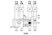
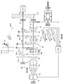
- FIG. 1 is a schematic configuration diagram in a state where an N position of a power transmission control device including a manual transmission for an HV-MT vehicle according to an embodiment of the present invention is selected.
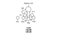
- FIG. It is the schematic diagram seen from the axial direction and the perpendicular
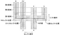
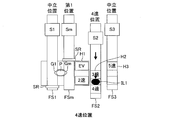
- FIG. 6 is a diagram for explaining a relationship between a shift pattern and first to third regions.
- FIG. 2 is a diagram corresponding to FIG.
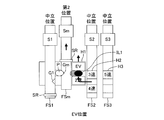
- FIG. 3 is a diagram corresponding to FIG. 2 in a state where an EV position is selected.
- FIG. 4 is a diagram corresponding to FIG. 3 in a state where an EV position and a second speed position are selected. It is a figure corresponding to Drawing 1 in the state where the 2nd gear position was selected. It is a figure corresponding to Drawing 2 in the state where the 2nd gear position was selected. It is a figure corresponding to Drawing 1 in the state where the 3rd speed position was selected. It is a figure corresponding to Drawing 2 in the state where the 3rd speed position was chosen. It is a figure corresponding to Drawing 1 in the state where the 4th speed position was chosen.
- FIG. 4 is a diagram corresponding to FIG. 3 in a state in which a 5-th gear position is selected.
- the present apparatus is “a manual transmission M / T having an engine E / G and a motor generator M / G as a power source and not having a torque converter, a friction clutch C / T, This is applied to the “vehicle equipped with the vehicle”, that is, the “HV-MT vehicle”.
- the “HV-MT vehicle” may be a front wheel drive vehicle, a rear wheel drive vehicle, or a four wheel drive vehicle.
- the engine E / G is a well-known internal combustion engine, for example, a gasoline engine that uses gasoline as fuel, or a diesel engine that uses light oil as fuel.
- the manual transmission M / T is a transmission (so-called manual transmission) that does not include a torque converter that selects a gear position according to the shift position of the shift lever SL operated by the driver.
- M / T includes an input shaft Ai that receives power from the output shaft Ae of the E / G, an output shaft Ao that outputs power to the drive wheels of the vehicle, and an MG shaft Am that receives power from the M / G. .
- the input shaft Ai, the output shaft Ao, and the MG axis Am are arranged in parallel to each other. In the example shown in FIG. 1, the MG axis Am is arranged coaxially with the output axis Ao.
- the MG axis Am may be arranged coaxially with the input axis Ai. Details of the configuration of the M / T will be described later.
- the friction clutch C / T is interposed between the E / G output shaft Ae and the M / T input shaft Ai.
- C / T rotates integrally with Ai with respect to the state of engagement of the friction plates (more specifically, the flywheel that rotates integrally with Ae) according to the operation amount (depression amount) of the clutch pedal CP operated by the driver.
- This is a known clutch in which the axial position of the friction plate changes.
- the C / T joined state (the axial position of the friction plate) is mechanically controlled according to the operation amount of the CP using a link mechanism or the like that mechanically connects the clutch pedal CP and the C / T (friction plate). Or may be adjusted electrically (in a so-called by-wire method) using the driving force of an actuator that operates based on the detection result of a sensor (sensor P1 to be described later) that detects the amount of operation of the CP. May be.
- the motor generator M / G has one of known configurations (for example, an AC synchronous motor), and for example, a rotor (not shown) rotates integrally with the MG shaft Am.
- EG torque the drive torque of the E / G output shaft Ae
- MG torque the drive torque of the MG shaft Am (torque of the output shaft of M / G) is referred to as “MG torque”.
- this device has a clutch operation amount sensor P1 that detects an operation amount (depression amount, clutch stroke, etc.) of the clutch pedal CP, and a brake operation amount that detects an operation amount (stepping force, presence / absence of operation, etc.) of the brake pedal BP.
- a sensor P2 an accelerator operation amount sensor P3 that detects the operation amount (accelerator opening) of the accelerator pedal AP, and a shift position sensor P4 that detects the position of the shift lever SL are provided.
- this device includes an electronic control unit ECU.
- the ECU controls the EG torque by controlling the fuel injection amount of the E / G (the opening degree of the throttle valve) based on the information from the sensors P1 to P4 and the other sensors, and the inverter.
- the MG torque is controlled by controlling (not shown).
- shift operation the operation of the shift lever SL in the left-right direction of the vehicle is called “select operation”, and the operation of the shift lever SL in the front-rear direction of the vehicle is called “shift operation”.
- “EV-2 select position”, “N position” (or “3-4 select position”), “5-speed select position”, and “R select position” are defined on the shift pattern.
- the range in which SL can be moved by the select operation (the range extending in the vehicle left-right direction, including “R select position”, “EV-2 select position”, “N position”, and “5-speed select position”). Called “neutral range”.
- the state in which the MG shaft Am is connected to the output shaft Ao (without the input Ai) so as to be able to transmit power is referred to as an “OUT connection state”.
- the ratio of the rotational speed of the input shaft Ai to the rotational speed of the output shaft Ao is called “MT reduction ratio”
- the ratio of the rotational speed of the MG axis Am to the rotational speed of the output shaft Ao” is “MG reduction ratio”.
- M / T includes sleeves S1, S2, S3, and Sm.
- S1, S2, and S3 are respectively “second speed” switching sleeves, which are fitted to corresponding hubs that rotate integrally with the output shaft Ao so that they cannot be rotated relative to each other but can be moved relative to each other in the axial direction.
- Sm is a sleeve for switching the connection state of the MG shaft Am, which is fitted to a gear that rotates integrally with the MG shaft Am so as not to be relatively rotatable and to be relatively movable in the axial direction.
- the sleeves S1, S2, S3, and Sm are integrally connected to the fork shafts FS1, FS2, FS3, and the switching shaft FSm, which are arranged in parallel to each other.
- FS1, FS2, FS3, and FSm (and therefore S1, S2, S3, and Sm) are respectively the first inner lever IL1 or the second inner lever IL2 (particularly FIG. 3) provided on the S & S shaft that is interlocked with the operation of the shift lever SL. 2) in the up / down direction (left / right direction in FIG. 1) during the shift operation, and is driven in the up / down direction (left / right direction in FIG. 1) during the shift operation. (Details will be described later).
- the S & S shaft is shown as a “select rotation type” that rotates around the axis by a select operation and translates in the axial direction by a shift operation.
- a “shift rotation type” that translates and rotates around the axis by a shift operation may be used.
- switching of the connection state of the MG shaft and switching the gear position will be described with reference to FIGS.
- first region “second region”, and “third region” are defined on the shift pattern.
- Switching of the connection state of the MG axis Am (that is, changing the axial position of the sleeve Sm) is performed based on the change of the region to which the SL position belongs among the first to third regions during the shift operation. Is called.
- the switching of the connection state of the MG shaft Am (that is, the change in the axial position of Sm) is performed in conjunction with the switching of the gear position.
- ⁇ N position> 1 to 3 show a state where SL is in the N position.
- FS1, FS2, and FS3 are all in the “neutral position”
- FSm is in the “first position”.
- the movement of FSm from the “first position” to the lower side in FIG. 2 is restricted by a locking member (not shown), and the movement of FS1 from the “neutral position” to the upper side in FIG. ing.
- the fork shaft FS1 and the switching shaft FSm arranged in parallel with each other are axially inserted into corresponding through holes formed in the EV-2 speed head H1 (corresponding to the “moving member”). Each is inserted so as to be relatively movable (in the vertical direction in FIG. 2).
- the head H1 is controlled to move upward in FIG. 2 with respect to the FSm by the snap ring SR fixed to the FSm.
- the head H1 moves downward in FIG. 2 with respect to the FS1 by the snap ring SR fixed to the FS1. Is regulated.
- a pin P is inserted in the head H1 so as to be movable in the left-right direction in FIG. In the state shown in FIG. 2, the pin P can selectively engage with the groove G1 formed on the side surface of the FS1 and the groove Gm formed on the side surface of the FSm.
- FIGS. 5 to 7 show a state in which the SL has moved from the N position to the EV shift completion position (via the EV-2 select position).
- the head H1 is pushed in the “EV” direction (upward in FIG. 6) by being pressed by the first inner lever IL1 of the S & S shaft. Driven (see IL1 shown in black in FIG. 6).
- the snap ring SR fixed to the FSm causes the FSm to move upward in FIG. 6 together with the H1.
- the FS1 is restricted from moving upward from the “neutral position” in FIG.
- the “EV position” substantially corresponds to the “first speed position” (corresponding to the “speed stage for low speed travel”).
- the neutral position and the EV shift completion position are identified based on, for example, the output result of the shift position sensor P4, the output result of a sensor that detects the position of the S & S shaft, and the like.
- the state in which the FSm is integrally connected to the H1 is not only when the SL moves from the “EV-2 select position” to the “EV shift completion position”, but after that, the SL changes from the “EV shift completion position” to the “EV ⁇ It is maintained until it returns to “2 select position”. Accordingly, as SL returns from the “EV shift completion position” to the “EV-2 select position”, FSm (and therefore Sm) changes from “second position” (see FIG. 6) to “first position”. Return to (see FIG. 2).
- FIG. 8 and FIG. 9 show a state in which SL has moved from the N position (via the EV-2 select position) to the second speed shift completion position.
- the head H1 is pressed in the “second speed” direction (downward in FIG. 9) by being pressed by the first inner lever IL1 of the S & S shaft. (Refer to IL1 shown in black in FIG. 9).
- the snap ring SR fixed to the FS 1 causes the FS 1 to move downward in FIG. 9 together with the H 1.
- ⁇ 3rd gear position> 10 and 11 show a state where SL has moved from the N position to the third speed shift completion position.
- the 3rd and 4th speed head H2 integrated with the FS2 is pushed to the “3rd speed” by being pressed by the first inner lever IL1 of the S & S shaft. ”(Upward in FIG. 11) (refer to IL1 shown in black in FIG. 11).
- FS2 (and therefore S2) moves from the “neutral position” to the “third speed position”.
- FSm (and hence Sm) is maintained in the “first position”
- FS1 and FS3 and therefore S1 and S3 are both maintained in the “neutral position”.
- ⁇ 4th gear position> 12 and 13 show a state where SL has moved from the N position to the 4th speed shift completion position. Since the operation in this case is the same as that in the case of the ⁇ third speed position>, detailed description thereof will be omitted.
- ⁇ 5-speed position> 14 to 16 show a state in which the SL has moved from the N position to the fifth gear shift completion position.
- the 5-speed head H3 integrated with the FS3 is “5-speed” by being pressed by the first inner lever IL1 of the S & S shaft. It is driven in the direction (upward in FIG. 15) (refer to IL1 shown in black in FIG. 15).
- FS3 (and therefore S3) moves from the “neutral position” to the “5-th gear position”.
- the distance between the 5th speed select position and the 5th speed shift completion position is shorter than the distance between the EV-2 select position and the EV shift completion position. Due to this, the “third position” is located between the “first position” and the “second position”. Note that FS1 and FS2 (thus, S1 and S2) are both maintained in the “neutral position”.
- the “N speed” is set between the input shaft Ai and the output shaft Ao via “GNi and GNo”.
- Corresponding power transmission systems are established (N: 2-5).
- the MT reduction ratio gradually decreases from “second speed” to “fifth speed”.
- the M / T includes the MT speed change mechanism M1 that can selectively set the MT reduction ratio in four stages from “second speed” to “fifth speed”.
- the MT transmission mechanism M1 includes a fixed gear GNi, an idle gear GNo, sleeves S1 to S3, and fork shafts FS1 to FS3 (N: 2 to 5).
- An MG connection switching mechanism M2 that can be selectively realized depending on the state is provided.
- the MG connection switching mechanism M2 includes a sleeve Sm, a switching shaft FSm, a hub Hm, gears Gmi, Gm1, Gm2, and Gmo.
- the E / G control by this apparatus is generally performed as follows.
- the E / G is maintained in a stopped state (a state in which fuel injection is not performed).
- the E / G stop state the E / G is started (fuel injection is started based on the selection of a gear position for HV traveling (any one of “2nd speed” to “5th speed”)).
- the EG torque is controlled based on the accelerator opening and the like.
- the E / G is maintained in the stopped state again based on the selection of “N” or “EV” or the stop of the vehicle.
- a torque of the internal combustion engine transmitted to the input shaft of the manual transmission via the clutch and a previously prepared map or the like that defines the relationship.
- the MG torque is determined based on the accelerator opening, etc. Be controlled. Then, based on the fact that the vehicle has stopped, M / G is again maintained in the stopped state.
- the MG reduction ratio becomes a large value during low-speed driving (that is, when the low-speed driving gear stage (EV) is selected). Is set. Therefore, since the MG torque is sufficiently amplified and transmitted to the output shaft Ao (accordingly, the drive wheel), the M / G can be reduced in size.
- the power transmission system between the MG shaft Am and the output shaft Ao is disconnected during high-speed travel (that is, when the gear stage for high-speed travel (5th speed) is selected). Therefore, the heat generation of M / G due to the high speed rotation of the MG axis Am can be suppressed. That is, it is possible to reduce the size of the M / G and to suppress heat generation due to the high speed rotation of the M / G.
- the present invention is not limited to the above embodiment, and various modifications can be employed within the scope of the present invention.
- the sleeves S1, S2, and S3 are all provided on the output shaft Ao, but may be provided on the input shaft Ai.
- a part (and corresponding idle gear) of the sleeves S1, S2, and S3 may be provided on the output shaft Ao, and the remaining (and corresponding idle gear) may be provided on the input shaft Ai.
- a shift stage in which a power transmission system is not established between the input and output shafts (different from neutral)” (EV) is included. All of the above may be set as “a shift stage in which a power transmission system is established between the input and output shafts”. In this case, “EV” is changed to “1st speed”, and HV traveling is possible in all 1st to 5th speeds.
Landscapes
- Engineering & Computer Science (AREA)
- Mechanical Engineering (AREA)
- Transportation (AREA)
- General Engineering & Computer Science (AREA)
- Power Engineering (AREA)
- Life Sciences & Earth Sciences (AREA)
- Sustainable Development (AREA)
- Sustainable Energy (AREA)
- Chemical & Material Sciences (AREA)
- Combustion & Propulsion (AREA)
- Gear-Shifting Mechanisms (AREA)
- Structure Of Transmissions (AREA)
- Hybrid Electric Vehicles (AREA)
Abstract
この手動変速機は、電動機M/Gの出力軸Amと変速機M/Tの出力軸Aoとの間の接続状態を運転者のシフトレバー操作によって確立された変速段に応じて変更する「接続切替機構M2」を備える。低速走行用の変速段(EV)が確立されている場合、Ao、Am間で動力伝達系統が確立され、且つ、電動機減速比(Aoの回転速度に対するAmの回転速度の割合)が第1減速比(>1)に設定される。中速走行用の変速段(2速~4速)が確立されている場合、Ao、Am間で動力伝達系統が確立され、且つ、電動機減速比が第2減速比(=1)に設定される。高速走行用の変速段(5速)が確立されている場合、Ao、Am間で動力伝達系統が確立されない。これにより、HV-MT車用の手動変速機であって、電動機を小型化でき、且つ電動機の高速回転に起因する電動機の発熱を抑制できるものが提供され得る。
Description
本発明は、動力源として内燃機関と電動機とを備えた車両に適用される手動変速機に関し、特に、内燃機関の出力軸と手動変速機の入力軸との間に摩擦クラッチが介装された車両に適用されるものに係わる。
従来より、動力源としてエンジンと電動機とを備えた所謂ハイブリッド車両が広く知られている(例えば、特開2000-224710号公報を参照)。ハイブリット車両では、電動機の出力軸が、内燃機関の出力軸、変速機の入力軸、及び変速機の出力軸の何れかに接続される構成が採用され得る。以下、内燃機関の出力軸の駆動トルクを「内燃機関駆動トルク」と呼び、電動機の出力軸の駆動トルクを「電動機駆動トルク」と呼ぶ。
近年、手動変速機と摩擦クラッチとを備えたハイブリッド車両(以下、「HV-MT車」と呼ぶ)に適用される動力伝達制御装置が開発されてきている。ここにいう「手動変速機」とは、運転者により操作されるシフトレバーのシフト位置に応じて変速段が選択されるトルクコンバータを備えない変速機(所謂、マニュアルトランスミッション、MT)である。また、ここにいう「摩擦クラッチ」とは、内燃機関の出力軸と手動変速機の入力軸との間に介装されて、運転者により操作されるクラッチペダルの操作量に応じて摩擦プレートの接合状態が変化するクラッチである。
以下、「(クラッチを介して)内燃機関から動力が入力される入力軸」と「電動機から動力が入力される出力軸」とを備えた、HV-MT車用の手動変速機を想定する。この手動変速機では、入力軸・出力軸間での動力伝達系統の確立の有無にかかわらず、電動機駆動トルクを手動変速機の出力軸(従って、駆動輪)に任意に伝達することができる。
ところで、この手動変速機では、低速走行時(即ち、低速走行用の変速段が選択されているとき)において、変速機の出力軸の回転速度に対する電動機の出力軸の回転速度の割合(電動機減速比)を大きくしたい、という要求があった。これにより、電動機駆動トルクが増幅されて手動変速機の出力軸(従って、駆動輪)に伝達されるため、電動機を小型化することができる。
また、高速走行時(即ち、高速走行用の変速段が選択されているとき)において、電動機の出力軸と手動変速機の出力軸との間の動力伝達系統を分断したい、という要求もあった。これにより、電動機の出力軸が高速で回転することに起因する電動機の発熱を抑制することができる。これらの要求が達成され得る手動変速機の到来が望まれていたところである。
本発明の目的は、電動機駆動トルクが出力軸に伝達されるHV-MT車用の手動変速機であって、電動機を小型化でき、且つ電動機の高速回転に起因する電動機の発熱を抑制できるものを提供することにある。
本発明に係る手動変速機は、前記内燃機関から動力が入力される入力軸と、前記電動機から動力が入力されるとともに前記車両の駆動輪へ動力を出力する出力軸と、変速機変速機構と、を備える。
変速機変速機構は、シフト操作部材をシフトパターン上において複数の変速段に対応するそれぞれのシフト完了位置に移動することによってそれぞれの変速段(ニュートラルとは異なる)を達成する。各変速段では、入力・出力軸間で動力伝達系統が確立されてもされなくてもよい。入力・出力軸間で動力伝達系統が確立されない(ニュートラルとは異なる)変速段としては、例えば、EV走行(電動機駆動トルクのみを利用した走行)用の変速段が挙げられる。入力・出力軸間で動力伝達系統が確立される変速段では、入力・出力軸間で「変速機減速比」が対応する変速段に対応するそれぞれの値に設定される動力伝達系統が確立される。
変速機変速機構は、前記低速走行用の変速段として、前記変速機の入力軸と前記変速機の出力軸との間で動力伝達系統が確立されない1つのEV走行用変速段を有し、前記中速走行用の変速段として、前記変速機の入力軸と前記変速機の出力軸との間で動力伝達系統が確立される1つ又は複数のハイブリッド(HV)走行(内燃機関及び電動機の両方の駆動力を利用した走行)用変速段を有し、前記高速走行用の変速段として、前記変速機の入力軸と前記変速機の出力軸との間で動力伝達系統が確立され且つ「変速機減速比」が前記中速走行用の変速段と比べて小さい1つのHV走行用変速段を有するように構成され得る。
本発明に係る手動変速機の特徴は、接続切替機構を備えたことにある。接続切替機構では、前記複数の変速段のうち低速走行用の変速段が確立されている場合には、前記変速機の出力軸と前記電動機の出力軸との間で動力伝達系統が確立されるとともに「電動機減速比」が第1減速比に設定される。前記複数の変速段のうち前記低速走行用の変速段より高速側の中速走行用の変速段が確立されている場合には、前記変速機の出力軸と前記電動機の出力軸との間で動力伝達系統が確立されるとともに「電動機減速比」が前記第1減速比より小さい第2減速比に設定される。前記複数の変速段のうち前記中速走行用の変速段より高速側の高速走行用の変速段が確立されている場合には、前記変速機の出力軸と前記電動機の出力軸との間で動力伝達系統が確立されない。
上記構成によれば、低速走行時(即ち、低速走行用の変速段が選択されているとき)において「電動機減速比」を大きい値に設定することができるので、電動機を小型化できる。加えて、高速走行時(即ち、高速走行用の変速段が選択されているとき)において電動機の出力軸と手動変速機の出力軸との間の動力伝達系統が分断されるので、電動機の高速回転に起因する電動機の発熱が抑制され得る。
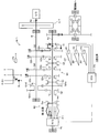
以下、本発明の実施形態に係る手動変速機M/Tを備えた車両の動力伝達制御装置の一例(以下、「本装置」と呼ぶ)について図面を参照しながら説明する。図1に示すように、本装置は、「動力源としてエンジンE/GとモータジェネレータM/Gとを備え、且つ、トルクコンバータを備えない手動変速機M/Tと、摩擦クラッチC/Tとを備えた車両」、即ち、上記「HV-MT車」に適用される。この「HV-MT車」は、前輪駆動車であっても、後輪駆動車であっても、4輪駆動車であってもよい。
(全体構成)
先ず、本装置の全体構成について説明する。エンジンE/Gは、周知の内燃機関であり、例えば、ガソリンを燃料として使用するガソリンエンジン、軽油を燃料として使用するディーゼルエンジンである。
先ず、本装置の全体構成について説明する。エンジンE/Gは、周知の内燃機関であり、例えば、ガソリンを燃料として使用するガソリンエンジン、軽油を燃料として使用するディーゼルエンジンである。
手動変速機M/Tは、運転者により操作されるシフトレバーSLのシフト位置に応じて変速段が選択されるトルクコンバータを備えない変速機(所謂、マニュアルトランスミッション)である。M/Tは、E/Gの出力軸Aeから動力が入力される入力軸Aiと、車両の駆動輪へ動力を出力する出力軸Aoと、M/Gから動力が入力されるMG軸Amと、を備える。入力軸Ai、出力軸Ao、及びMG軸Amは互いに平行に配置されている。図1に示す例では、MG軸Amは、出力軸Aoと同軸に配置されている。MG軸Amは、入力軸Aiと同軸に配置されていてもよい。M/Tの構成の詳細は後述する。
摩擦クラッチC/Tは、E/Gの出力軸AeとM/Tの入力軸Aiとの間に介装されている。C/Tは、運転者により操作されるクラッチペダルCPの操作量(踏み込み量)に応じて摩擦プレートの接合状態(より具体的には、Aeと一体回転するフライホイールに対する、Aiと一体回転する摩擦プレートの軸方向位置)が変化する周知のクラッチである。
C/Tの接合状態(摩擦プレートの軸方向位置)は、クラッチペダルCPとC/T(摩擦プレート)とを機械的に連結するリンク機構等を利用してCPの操作量に応じて機械的に調整されてもよいし、CPの操作量を検出するセンサ(後述するセンサP1)の検出結果に基づいて作動するアクチュエータの駆動力を利用して電気的に(所謂バイ・ワイヤ方式で)調整されてもよい。
モータジェネレータM/Gは、周知の構成(例えば、交流同期モータ)の1つを有していて、例えば、ロータ(図示せず)がMG軸Amと一体回転するようになっている。以下、E/Gの出力軸Aeの駆動トルクを「EGトルク」と呼び、MG軸Am(M/Gの出力軸のトルク)の駆動トルクを「MGトルク」と呼ぶ。
また、本装置は、クラッチペダルCPの操作量(踏み込み量、クラッチストローク等)を検出するクラッチ操作量センサP1と、ブレーキペダルBPの操作量(踏力、操作の有無等)を検出するブレーキ操作量センサP2と、アクセルペダルAPの操作量(アクセル開度)を検出するアクセル操作量センサP3と、シフトレバーSLの位置を検出するシフト位置センサP4と、を備えている。
更に、本装置は、電子制御ユニットECUを備えている。ECUは、上述のセンサP1~P4、並びにその他のセンサ等からの情報等に基づいて、E/Gの燃料噴射量(スロットル弁の開度)を制御することでEGトルクを制御するとともに、インバータ(図示せず)を制御することでMGトルクを制御する。
(M/Tの構成)
以下、図1~図4を参照しながら、M/Tの構成について説明する。図1、及び図4に示すシフトレバーSLのシフトパターンから理解できるように、本例では、選択される変速段(シフト完了位置)として、前進用の5つの変速段(EV、2速~5速)、及び後進用の1つの変速段(R)が設けられている。以下、後進用の変速段(R)についての説明は省略する。
以下、図1~図4を参照しながら、M/Tの構成について説明する。図1、及び図4に示すシフトレバーSLのシフトパターンから理解できるように、本例では、選択される変速段(シフト完了位置)として、前進用の5つの変速段(EV、2速~5速)、及び後進用の1つの変速段(R)が設けられている。以下、後進用の変速段(R)についての説明は省略する。
図4に示すように、シフトパターンにおいて、車両の左右方向のシフトレバーSLの操作を「セレクト操作」と呼び、車両の前後方向のシフトレバーSLの操作を「シフト操作」と呼ぶ。図4に示すように、シフトパターン上において、「EV-2セレクト位置」、「N位置」(又は「3-4セレクト位置」)、「5速セレクト位置」、及び「Rセレクト位置」を定義する。また、セレクト操作によってSLが移動可能となる範囲(「Rセレクト位置」、「EV-2セレクト位置」、「N位置」、及び「5速セレクト位置」を含む、車両左右方向に延びる範囲)を「ニュートラル範囲」と呼ぶ。
以下、説明の便宜上、MG軸Amが(入力Aiを介することなく)出力軸Aoと動力伝達可能に接続される状態を「OUT接続状態」と呼ぶ。また、「出力軸Aoの回転速度に対する入力軸Aiの回転速度の割合」を「MT減速比」と呼び、「出力軸Aoの回転速度に対するMG軸Amの回転速度の割合」を「MG減速比」と呼ぶ。
M/Tは、スリーブS1、S2、S3、及びSmを備える。S1、S2、及びS3はそれぞれ、出力軸Aoと一体回転する対応するハブに相対回転不能且つ軸方向に相対移動可能に嵌合された、「2速」切り替え用のスリーブ、「3速-4速」切り替え用のスリーブ、及び「5速」切り替え用のスリーブである。Smは、MG軸Amと一体回転するギヤに相対回転不能且つ軸方向に相対移動可能に嵌合された、MG軸Amの接続状態の切り替え用のスリーブである。
図2から理解できるように、スリーブS1、S2、S3、及びSmはそれぞれ、互いに平行に配置された、フォークシャフトFS1、FS2、FS3、及び切替シャフトFSmと一体に連結されている。FS1、FS2、FS3、及びFSm(従って、S1、S2、S3、及びSm)はそれぞれ、シフトレバーSLの操作と連動するS&Sシャフトに設けられた第1インナレバーIL1又は第2インナレバーIL2(特に図3を参照)のシフト操作時における図2の上下方向(図1では左右方向)の移動に連動して、シフト操作時にて図2の上下方向(図1では左右方向)に駆動される。(詳細は後述)。
なお、図2及び図3では、S&Sシャフトとして、セレクト操作によって軸中心に回動し且つシフト操作によって軸方向に平行移動する「セレクト回転型」が示されているが、セレクト操作によって軸方向に平行移動し且つシフト操作によって軸中心に回動する「シフト回転型」が使用されてもよい。
(MG軸の接続状態の切り替え、並びに、変速段の切り替え)
以下、図1~図16を参照しながら、MG軸の接続状態の切り替え、並びに、変速段の切り替えについて説明する。図4に示すように、シフトパターン上において、「第1領域」、「第2領域」、及び「第3領域」を定義する。MG軸Amの接続状態の切り替え(即ち、スリーブSmの軸方向位置の変更)は、シフト操作中において第1~第3領域のうちでSLの位置が属する領域が変更されることに基づいて行われる。換言すれば、MG軸Amの接続状態の切り替え(即ち、Smの軸方向位置の変更)は、変速段の切り替えに連動して行われる。
以下、図1~図16を参照しながら、MG軸の接続状態の切り替え、並びに、変速段の切り替えについて説明する。図4に示すように、シフトパターン上において、「第1領域」、「第2領域」、及び「第3領域」を定義する。MG軸Amの接続状態の切り替え(即ち、スリーブSmの軸方向位置の変更)は、シフト操作中において第1~第3領域のうちでSLの位置が属する領域が変更されることに基づいて行われる。換言すれば、MG軸Amの接続状態の切り替え(即ち、Smの軸方向位置の変更)は、変速段の切り替えに連動して行われる。
<N位置>
図1~図3は、SLがN位置にある状態を示す。この状態では、FS1、FS2、及びFS3(従って、S1、S2、及びS3)が共に「中立位置」にあり、FSm(従って、Sm)が「第1位置」にある。FSmは、図示しない係止部材によって「第1位置」から図2の下方への移動が規制され、FS1は、図示しない係止部材によって「中立位置」から図2の上方への移動が規制されている。
図1~図3は、SLがN位置にある状態を示す。この状態では、FS1、FS2、及びFS3(従って、S1、S2、及びS3)が共に「中立位置」にあり、FSm(従って、Sm)が「第1位置」にある。FSmは、図示しない係止部材によって「第1位置」から図2の下方への移動が規制され、FS1は、図示しない係止部材によって「中立位置」から図2の上方への移動が規制されている。
図2に示すように、互いに平行に配置されたフォークシャフトFS1及び切替シャフトFSmが、EV-2速用ヘッドH1(前記「移動部材」に対応する)に形成された対応する貫通孔に軸方向(図2の上下方向)に相対移動可能にそれぞれ挿入されている。ヘッドH1は、FSmに固定されたスナップリングSRによって、FSmに対する図2の上方への相対移動が規制されるとともに、FS1に固定されたスナップリングSRによって、FS1に対する図2の下方への相対移動が規制される。
ヘッドH1の内部には、ピンPが図2の左右方向に移動可能に挿入されている。ピンPは、図2に示す状態において、FS1の側面に形成された溝G1と、FSmの側面に形成された溝Gmとに選択的に係合可能となっている。
図1に示すように、この状態では、S1、S2、及びS3はそれぞれ、対応する何れの遊転ギヤとも係合していない。即ち、SLが「N位置」(より正確には、ニュートラル位置)にある状態では、入力・出力軸Ai,Ao間で動力伝達系統が確立されない。
他方、図1に示すように、Smが「第1位置」にあるとき、Smは出力軸Aoと一体回転するハブHmと係合する。この結果、MG軸Amと出力軸Aoとの間で、「MG減速比=1」の動力伝達系統が確立される。以上、SLがN位置にあるとき、より正確には、SLがニュートラル範囲(図4の第1領域)にあるとき、入力・出力軸Ai,Ao間で動力伝達系統が確立されず、且つ、「MG減速比=1」の「OUT接続状態」が達成される。
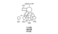
<EV位置>
図5~図7は、SLが、N位置から(EV-2セレクト位置を経由して)EVシフト完了位置に移動した状態を示す。SLが「EV-2セレクト位置」から「EVシフト完了位置」に移動しようとすると、S&Sシャフトの第1インナレバーIL1に押圧されることによってヘッドH1が「EV」方向(図6では上方向)に駆動される(図6において、黒で示したIL1を参照)。この結果、FSmに固定されたスナップリングSRの作用によってFSmがH1と一体で図6の上方向に移動しようとする。一方、上述のように、FS1は「中立位置」から図6の上方への移動が規制されている。この結果、ピンPと溝Gmとの図中の上下方向の位置がなおも合致し続ける一方で、ピンPと溝G1との図中の上下方向の位置が合致しなくなる。このため、ピンPは、図6の右方向に移動して溝Gmのみと係合し、FSmはH1と一体に連結される(FS1はH1と相対移動可能に維持される)。
図5~図7は、SLが、N位置から(EV-2セレクト位置を経由して)EVシフト完了位置に移動した状態を示す。SLが「EV-2セレクト位置」から「EVシフト完了位置」に移動しようとすると、S&Sシャフトの第1インナレバーIL1に押圧されることによってヘッドH1が「EV」方向(図6では上方向)に駆動される(図6において、黒で示したIL1を参照)。この結果、FSmに固定されたスナップリングSRの作用によってFSmがH1と一体で図6の上方向に移動しようとする。一方、上述のように、FS1は「中立位置」から図6の上方への移動が規制されている。この結果、ピンPと溝Gmとの図中の上下方向の位置がなおも合致し続ける一方で、ピンPと溝G1との図中の上下方向の位置が合致しなくなる。このため、ピンPは、図6の右方向に移動して溝Gmのみと係合し、FSmはH1と一体に連結される(FS1はH1と相対移動可能に維持される)。
このように、FSmがH1と一体に連結されることによって、SLが「EV-2セレクト位置」から「EVシフト完了位置」へ移動すると(従って、H1が図6の上方向へ移動すると)、図6に示すように、FSm(従って、Sm)が「第1位置」より図6の上方向の位置に移動する。以下、FSm及びSmについて、この位置を「第2位置」と呼ぶ。FS1、FS2、及びFS3(従って、S1、S2、及びS3)は共に「中立位置」に維持される。
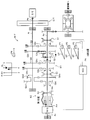
図5に示すように、この状態では、S1、S2、及びS3はそれぞれ、対応する何れの遊転ギヤとも係合していない。即ち、SLが「EVシフト完了位置」にある状態では、「N位置」(より正確には、ニュートラル位置)にある状態と同様、入力・出力軸Ai,Ao間で動力伝達系統が確立されない。
他方、図5に示すように、Smが「第2位置」にあるとき、Smは、出力軸Aoに設けられた遊転ギヤGmiと係合する。遊転ギヤGmiは、入力軸Aiに設けられた遊転ギヤGm1、Gm2を介して、出力軸Aoに設けられた固定ギヤGmoと動力伝達可能に常時接続されている。ここで、(Gmiの歯数)<(Gm1の歯数)、並びに、(Gm2の歯数)<(Gmoの歯数)という関係が成立している。この結果、MG軸Amと出力軸Aoとの間で、「MG減速比>1」の動力伝達系統が確立される。
以上、SLがEVシフト完了位置(図4の第2領域)にあるとき、入力・出力軸Ai,Ao間で動力伝達系統が確立されず、且つ、「MG減速比>1」の「OUT接続状態」が達成される。従って、摩擦クラッチC/Tを接合状態に維持し、且つ、E/Gを停止状態(E/Gの出力軸Aeの回転が停止した状態)に維持しながら、MGトルクのみを利用して車両が走行する状態(即ち、「EV走行」)を実現することができる(図5の太線を参照)。
EV走行は、主として車両発進時に活用される。即ち、シフトパターン上において、「EV位置」は、実質的には「1速位置」(前記「低速走行用の変速段」に対応)に相当する。なお、ニュートラル位置とEVシフト完了位置との識別は、例えば、シフト位置センサP4の出力結果、S&Sシャフトの位置を検出するセンサの出力結果等に基づいて達成される。
FSmがH1と一体に連結された状態は、SLが「EV-2セレクト位置」から「EVシフト完了位置」へ移動するときのみならず、その後においてSLが「EVシフト完了位置」から「EV-2セレクト位置」へ戻るときまで維持される。従って、SLが「EVシフト完了位置」から「EV-2セレクト位置」へ戻ることに伴って、FSm(従って、Sm)は、「第2位置」(図6を参照)から「第1位置」(図2を参照)へと戻る。
なお、以上説明した「SLがEV-2セレクト位置とEVシフト完了位置との間で移動する際のFSm(従って、Sm)の動作」は、SLがRセレクト位置とRシフト完了位置との間で移動する際にも同様になされる(図6における微細なドットで示したIL1、並びに、図7における破線で示したIL1,IL2を参照)。従って、SLがRシフト完了位置(図4の第2領域)にあるとき、MGを逆向きに回転させることによって「EV走行」による後進を実現することができる。EVシフト完了位置とRシフト完了位置との識別も、例えば、シフト位置センサP4の出力結果、S&Sシャフトの位置を検出するセンサの出力結果等に基づいて達成される。
<2速位置>
図8及び図9(及び図7)は、SLが、N位置から(EV-2セレクト位置を経由して)2速シフト完了位置に移動した状態を示す。SLが「EV-2セレクト位置」から「2速シフト完了位置」に移動しようとすると、S&Sシャフトの第1インナレバーIL1に押圧されることによってヘッドH1が「2速」方向(図9では下方向)に駆動される(図9において、黒で示したIL1を参照)。この結果、FS1に固定されたスナップリングSRの作用によってFS1がH1と一体で図9の下方向に移動しようとする。一方、上述のように、FSmは「中立位置」から図9の下方への移動が規制されている。この結果、ピンPと溝Gmとの図中の上下方向の位置が合致しなくなる。このため、ピンPは、図9の左方向に移動して溝G1のみと係合し、FS1はH1と一体に連結される(FSmはH1と相対移動可能に維持される)。
図8及び図9(及び図7)は、SLが、N位置から(EV-2セレクト位置を経由して)2速シフト完了位置に移動した状態を示す。SLが「EV-2セレクト位置」から「2速シフト完了位置」に移動しようとすると、S&Sシャフトの第1インナレバーIL1に押圧されることによってヘッドH1が「2速」方向(図9では下方向)に駆動される(図9において、黒で示したIL1を参照)。この結果、FS1に固定されたスナップリングSRの作用によってFS1がH1と一体で図9の下方向に移動しようとする。一方、上述のように、FSmは「中立位置」から図9の下方への移動が規制されている。この結果、ピンPと溝Gmとの図中の上下方向の位置が合致しなくなる。このため、ピンPは、図9の左方向に移動して溝G1のみと係合し、FS1はH1と一体に連結される(FSmはH1と相対移動可能に維持される)。
このように、FS1がH1と一体に連結されることによって、SLが「EV-2セレクト位置」から「2速シフト完了位置」へ移動すると(従って、H1が図9の下方向へ移動すると)、図9に示すように、FS1(従って、S1)が「中立位置」より「2速位置」へ移動する。FSm(従って、Sm)は「第1位置」に維持され、FS2、及びFS3(従って、S2、及びS3)は共に「中立位置」に維持される。
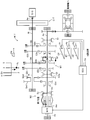
図8に示すように、この状態では、S1が、出力軸Aoに設けられた遊転ギヤG2oと係合する。遊転ギヤG2oは、入力軸Aiに設けられた固定ギヤG2iと常時噛合している。この結果、入力軸Aiと出力軸Aoとの間で、「G2i及びG2o」を介してEGトルクについての「2速」に対応する動力伝達系統が確立される。即ち、MT減速比は(G2oの歯数/G2iの歯数)(=「2速」)となる。
加えて、Smが「第1位置」に維持されることによって、<N位置>の場合と同様、「MG減速比=1」の「OUT接続状態」が実現される。従って、MGトルクとEGトルクの両方を利用して車両が走行する状態(即ち、「HV走行」)を実現することができる(図8の太線を参照)。
FS1がH1と一体に連結された状態は、SLが「EV-2セレクト位置」から「2速シフト完了位置」へ移動するときのみならず、その後においてSLが「2速シフト完了位置」から「EV-2セレクト位置」へ戻るときまで維持される。従って、SLが「2速シフト完了位置」から「EV-2セレクト位置」へ戻ることに伴って、FS1(従って、S1)は、「2速位置」(図9を参照)から「中立位置」(図2を参照)へと戻る。
<3速位置>
図10及び図11(及び図3)は、SLが、N位置から3速シフト完了位置に移動した状態を示す。SLが「N位置」から「3速シフト完了位置」に移動しようとすると、S&Sシャフトの第1インナレバーIL1に押圧されることによって、FS2と一体の3速-4速用ヘッドH2が「3速」方向(図11では上方向)に駆動される(図11において、黒で示したIL1を参照)。この結果、FS2(従って、S2)が「中立位置」より「3速位置」へ移動する。FSm(従って、Sm)は「第1位置」に維持され、FS1、及びFS3(従って、S1、及びS3)は共に「中立位置」に維持される。
図10及び図11(及び図3)は、SLが、N位置から3速シフト完了位置に移動した状態を示す。SLが「N位置」から「3速シフト完了位置」に移動しようとすると、S&Sシャフトの第1インナレバーIL1に押圧されることによって、FS2と一体の3速-4速用ヘッドH2が「3速」方向(図11では上方向)に駆動される(図11において、黒で示したIL1を参照)。この結果、FS2(従って、S2)が「中立位置」より「3速位置」へ移動する。FSm(従って、Sm)は「第1位置」に維持され、FS1、及びFS3(従って、S1、及びS3)は共に「中立位置」に維持される。
図10に示すように、この状態では、S1が、出力軸Aoに設けられた遊転ギヤG3oと係合する。遊転ギヤG3oは、入力軸Aiに設けられた固定ギヤG3iと常時噛合している。この結果、入力軸Aiと出力軸Aoとの間で、「G3i及びG3o」を介してEGトルクについての「3速」に対応する動力伝達系統が確立される。即ち、MT減速比は(G3oの歯数/G3iの歯数)(=「3速」)となる。
加えて、Smが「第1位置」に維持されることによって「MG減速比=1」の「OUT接続状態」が実現される。従って、MGトルクとEGトルクの両方を利用して車両が走行する状態(即ち、「HV走行」)を実現することができる(図10の太線を参照)。
<4速位置>
図12及び図13(及び図3)は、SLが、N位置から4速シフト完了位置に移動した状態を示す。この場合の作動は、<3速位置>の場合と同様であるのでその詳細な説明を省略する。この状態では、入力軸Aiと出力軸Aoとの間で、「G4i及びG4o」を介してEGトルクについての「4速」に対応する動力伝達系統が確立される。即ち、MT減速比は(G4oの歯数/G4iの歯数)(=「4速」)となる。加えて、「MG減速比=1」の「OUT接続状態」が実現される。従って、MGトルクとEGトルクの両方を利用して車両が走行する状態(即ち、「HV走行」)を実現することができる(図12の太線を参照)。
図12及び図13(及び図3)は、SLが、N位置から4速シフト完了位置に移動した状態を示す。この場合の作動は、<3速位置>の場合と同様であるのでその詳細な説明を省略する。この状態では、入力軸Aiと出力軸Aoとの間で、「G4i及びG4o」を介してEGトルクについての「4速」に対応する動力伝達系統が確立される。即ち、MT減速比は(G4oの歯数/G4iの歯数)(=「4速」)となる。加えて、「MG減速比=1」の「OUT接続状態」が実現される。従って、MGトルクとEGトルクの両方を利用して車両が走行する状態(即ち、「HV走行」)を実現することができる(図12の太線を参照)。
<5速位置>
図14~図16は、SLが、N位置から5速シフト完了位置に移動した状態を示す。SLが「5速セレクト位置」から「5速シフト完了位置」に移動しようとすると、S&Sシャフトの第1インナレバーIL1に押圧されることによって、FS3と一体の5速用ヘッドH3が「5速」方向(図15では上方向)に駆動される(図15において、黒で示したIL1を参照)。この結果、FS3(従って、S3)が「中立位置」より「5速位置」へ移動する。
図14~図16は、SLが、N位置から5速シフト完了位置に移動した状態を示す。SLが「5速セレクト位置」から「5速シフト完了位置」に移動しようとすると、S&Sシャフトの第1インナレバーIL1に押圧されることによって、FS3と一体の5速用ヘッドH3が「5速」方向(図15では上方向)に駆動される(図15において、黒で示したIL1を参照)。この結果、FS3(従って、S3)が「中立位置」より「5速位置」へ移動する。
加えて、図16に示すように、SLが「5速セレクト位置」にある状態では、S&Sシャフトの第2インナレバーIL2がヘッドH1と係合するようになる。従って、第2インナレバーIL2に押圧されることによって、ヘッドH1も「EV」方向(図15では上方向)に駆動される(図15において、黒で示したIL2を参照)。この結果、FSmがH1と一体に連結されることによって、図15に示すように、FSm(従って、Sm)も「第1位置」より図15の上方向の位置に移動する。以下、FSm及びSmについて、この位置を「第3位置」と呼ぶ。
図4から理解できるように、シフトパターン上において、5速セレクト位置と5速シフト完了位置との間の距離は、EV-2セレクト位置とEVシフト完了位置との間の距離よりも短い。このことに起因して、この「第3位置」は、「第1位置」と「第2位置」との中間に位置する。なお、FS1、及びFS2(従って、S1、及びS2)は共に「中立位置」に維持される。
図14に示すように、この状態では、S3が、出力軸Aoに設けられた遊転ギヤG5oと係合する。この結果、入力軸Aiと出力軸Aoとの間で、「G5i及びG5o」を介してEGトルクについての「5速」に対応する動力伝達系統が確立される。即ち、MT減速比は(G5oの歯数/G5iの歯数)(=「5速」)となる。
他方、図14に示すように、Smが「第3位置」にあるとき、Smは、ハブHm及び遊転ギヤGmiの何れにも係合しない。即ち、MG軸Amと出力軸Aoとの間で動力伝達系統が確立されない。以上、SLが5速シフト完了位置(図4の第3領域)にあるとき、M/Gを停止状態(MG軸Amの回転が停止した状態)に維持しながら、EGトルクのみを利用して車両が走行する状態(即ち、「EG走行」)を実現することができる(図14の太線を参照)。
以上、SLが「EVシフト完了位置」にある場合(即ち、「低速走行用の変速段」が確立されている場合」)、入力・出力軸Ai,Ao間で動力伝達系統が確立されず、且つ、「MG減速比>1」の「OUT接続状態」が達成される。従って、大きなMG減速比を利用したEV走行が可能となる。また、SLが「2速~4速シフト完了位置」の何れかにある場合(即ち、「中速走行用の変速段」が確立されている場合」)、入力・出力軸Ai,Ao間で動力伝達系統が確立され、且つ、「MG減速比=1」の「OUT接続状態」が達成される。従って、HV走行が可能となる。また、SLが「5速シフト完了位置」にある場合(即ち、「高速走行用の変速段」が確立されている場合」)、入力・出力軸Ai,Ao間で動力伝達系統が確立され、且つ、MG軸Amと出力軸Aoとの間で動力伝達系統が確立されない。従って、EG走行が可能となる。
なお、シフトレバーSLが「2速~5速のシフト完了位置」の何れかにある場合、入力軸Aiと出力軸Aoとの間で、「GNi及びGNo」を介して、「N速」に対応する動力伝達系統が確立される(N:2~5)。このとき、MT減速比は(GNoの歯数/GNiの歯数)(=「N速」)となる(N:2~5)。「2速」から「5速」に向けて、MT減速比は次第に小さくなっていく。
以上、M/Tは、MT減速比を「2速」~「5速」の4段階に選択的に設定可能なMT変速機構M1を備えている。MT変速機構M1は、固定ギヤGNi、遊転ギヤGNo、スリーブS1~S3、及びフォークシャフトFS1~FS3等から構成される(N:2~5)。また、M/Tは、MG軸Amと出力軸Aoとの接続状態を、「MG減速比>1」の接続状態、「MG減速比=1」の接続状態、及び、非接続状態の3つの状態に選択的に実現可能なMG接続切替機構M2を備えている。MG接続切替機構M2は、スリーブSm、切替シャフトFSm、ハブHm、ギヤGmi、Gm1、Gm2、Gmo等から構成される。
(E/Gの制御)
本装置によるE/Gの制御は、大略的に以下のようになされる。車両が停止しているとき、或いは、「N」又は「EV」が選択されているとき、E/Gが停止状態(燃料噴射がなされない状態)に維持される。E/Gの停止状態において、HV走行用の変速段(「2速」~「5速」の何れか)が選択されたことに基づいて、E/Gが始動される(燃料噴射が開始される)。E/Gの稼働中(燃料噴射がなされている間)では、アクセル開度等に基づいてEGトルクが制御される。E/Gの稼働中において、「N」又は「EV」が選択されたこと、或いは、車両が停止したことに基づいて、E/Gが再び停止状態に維持される。
本装置によるE/Gの制御は、大略的に以下のようになされる。車両が停止しているとき、或いは、「N」又は「EV」が選択されているとき、E/Gが停止状態(燃料噴射がなされない状態)に維持される。E/Gの停止状態において、HV走行用の変速段(「2速」~「5速」の何れか)が選択されたことに基づいて、E/Gが始動される(燃料噴射が開始される)。E/Gの稼働中(燃料噴射がなされている間)では、アクセル開度等に基づいてEGトルクが制御される。E/Gの稼働中において、「N」又は「EV」が選択されたこと、或いは、車両が停止したことに基づいて、E/Gが再び停止状態に維持される。
(M/Gの制御)
本装置によるM/Gの制御は、大略的に以下のようになされる。車両が停止しているとき、或いは、「N」又は「5速」が選択されているとき、M/Gが停止状態(MGトルク=0)に維持される。M/Gの停止状態において、「EV」が選択されたことに基づいて、MGトルクを利用した通常発進制御が開始される。通常発進制御では、MGトルクがアクセル開度及びクラッチストロークに基づいて制御される。通常発進制御でのMGトルクは、「手動変速機と摩擦クラッチとを備え且つ動力源として内燃機関のみを搭載した通常車両」が「1速」で発進する際における「アクセル開度及びクラッチストローク」と「クラッチを介して手動変速機の入力軸へ伝達される内燃機関のトルク」との関係を規定する予め作製されたマップ等を利用して決定される。通常発進制御の終了後は、「EV」の選択時、或いは、「2速」~「4速」(複数のHV走行用変速段)の選択時において、アクセル開度等に基づいてMGトルクが制御される。そして、車両が停止したことに基づいて、M/Gが再び停止状態に維持される。
本装置によるM/Gの制御は、大略的に以下のようになされる。車両が停止しているとき、或いは、「N」又は「5速」が選択されているとき、M/Gが停止状態(MGトルク=0)に維持される。M/Gの停止状態において、「EV」が選択されたことに基づいて、MGトルクを利用した通常発進制御が開始される。通常発進制御では、MGトルクがアクセル開度及びクラッチストロークに基づいて制御される。通常発進制御でのMGトルクは、「手動変速機と摩擦クラッチとを備え且つ動力源として内燃機関のみを搭載した通常車両」が「1速」で発進する際における「アクセル開度及びクラッチストローク」と「クラッチを介して手動変速機の入力軸へ伝達される内燃機関のトルク」との関係を規定する予め作製されたマップ等を利用して決定される。通常発進制御の終了後は、「EV」の選択時、或いは、「2速」~「4速」(複数のHV走行用変速段)の選択時において、アクセル開度等に基づいてMGトルクが制御される。そして、車両が停止したことに基づいて、M/Gが再び停止状態に維持される。
(作用・効果)
上記のように、本発明の実施形態に係る手動変速機M/Tでは、低速走行時(即ち、低速走行用の変速段(EV)が選択されているとき)、MG減速比が大きい値に設定される。従って、MGトルクが十分に増幅されて出力軸Ao(従って、駆動輪)に伝達されるため、M/Gを小型化することができる。
上記のように、本発明の実施形態に係る手動変速機M/Tでは、低速走行時(即ち、低速走行用の変速段(EV)が選択されているとき)、MG減速比が大きい値に設定される。従って、MGトルクが十分に増幅されて出力軸Ao(従って、駆動輪)に伝達されるため、M/Gを小型化することができる。
加えて、高速走行時(即ち、高速走行用の変速段(5速)が選択されているとき)、MG軸Amと出力軸Aoとの間の動力伝達系統が分断される。従って、MG軸Amの高速回転に起因するM/Gの発熱が抑制され得る。即ち、M/Gを小型化でき、且つM/Gの高速回転に起因する発熱を抑制することができる。
本発明は上記実施形態に限定されることはなく、本発明の範囲内において種々の変形例を採用することができる。例えば、上記実施形態では、スリーブS1、S2、S3(及び対応するそれぞれの遊転ギヤ)が共に出力軸Aoに設けられているが、共に入力軸Aiに設けられていてもよい。また、スリーブS1、S2、S3のうちの一部(及び対応する遊転ギヤ)が出力軸Aoに、残り(及び対応する遊転ギヤ)が入力軸Aiに設けられていてもよい。
また、上記実施形態では、複数の変速段のうちで「入力・出力軸間で動力伝達系統が確立されない(ニュートラルとは異なる)変速段」(EV)が含まれているが、複数の変速段の全てを「入力・出力軸間で動力伝達系統が確立される変速段」としてもよい。この場合、「EV」が「1速」に変更されて、1~5速の全てにおいてHV走行が可能となる。
また、上記実施形態では、前記「電動機減速比」の「第1減速比」及び「第2減速比」(第1減速比>第2減速比)として、「第1減速比>1」、「第2減速比=1」が採用されているが、「第1減速比=A」、「第2減速比=B」(A>B>1、A>1>B、1>A>B)が採用されてもよい。
Claims (4)
- 動力源として内燃機関(E/G)と電動機(M/G)とを備えた車両に適用される、トルクコンバータを備えない手動変速機(M/T)であって、
前記内燃機関から動力が入力される入力軸(Ai)と、
前記電動機から動力が入力されるとともに前記車両の駆動輪へ動力を出力する出力軸(Ao)と、
運転者により操作されるシフト操作部材(SL)をシフトパターン上において複数の変速段(EV、2速~5速)に対応するそれぞれのシフト完了位置に移動することによってそれぞれの変速段を確立する変速機変速機構(M1)と、
を備えた手動変速機であって、
前記複数の変速段のうち低速走行用の変速段(EV)が確立されている場合には、前記変速機の出力軸(Ao)と前記電動機の出力軸(Am)との間で動力伝達系統が確立されるとともに前記変速機の出力軸の回転速度に対する前記電動機の出力軸の回転速度の割合である電動機減速比が第1減速比に設定される第1状態を実現し、
前記複数の変速段のうち前記低速走行用の変速段より高速側の中速走行用の変速段(2速~4速)が確立されている場合には、前記変速機の出力軸と前記電動機の出力軸との間で動力伝達系統が確立されるとともに前記電動機減速比が前記第1減速比より小さい第2減速比に設定される第2状態を実現し、
前記複数の変速段のうち前記中速走行用の変速段より高速側の高速走行用の変速段(5速)が確立されている場合には、前記変速機の出力軸と前記電動機の出力軸との間で動力伝達系統が確立されない第3状態を実現する、接続切替機構(M2)を備えた、手動変速機。 - 請求項1に記載の手動変速機において、
前記変速機変速機構は、
前記低速走行用の変速段として、前記内燃機関及び前記電動機の駆動力のうち前記電動機の駆動力のみを利用して走行するための変速段であって前記変速機の入力軸(Ai)と前記変速機の出力軸(Ao)との間で動力伝達系統が確立されない1つの電動機走行用変速段(EV)を有し、
前記中速走行用の変速段として、前記内燃機関及び前記電動機の両方の駆動力を利用し得る状態で走行するための変速段であって前記変速機の入力軸(Ai)と前記変速機の出力軸(Ao)との間で動力伝達系統が確立される1つ又は複数のハイブリッド走行用変速段(2速~4速)を有し、
前記高速走行用の変速段として、前記内燃機関及び前記電動機の両方の駆動力を利用し得る状態で走行するための変速段であって前記変速機の入力軸(Ai)と前記変速機の出力軸(Ao)との間で動力伝達系統が確立され且つ前記変速機の出力軸の回転速度に対する前記変速機の入力軸の回転速度の割合である変速機減速比が前記中速走行用の変速段と比べて小さい1つのハイブリッド走行用変速段(5速)を有するように構成された、手動変速機。 - 請求項2に記載の手動変速機において、
前記変速機変速機構は、
それぞれが前記変速機の入力軸又は出力軸に相対回転不能に設けられた複数の固定ギヤであってそれぞれが前記複数のハイブリッド走行用変速段(2速~5速)のそれぞれに対応する複数の固定ギヤ(G2i、G3i、G4i、G5i)と、
それぞれが前記変速機の入力軸又は前記変速機の出力軸に相対回転可能に設けられた複数の遊転ギヤであってそれぞれが前記複数のハイブリッド走行用変速段のそれぞれに対応するとともに対応するハイブリッド走行用変速段の前記固定ギヤと常時歯合する複数の遊転ギヤ(G2o、G3o、G4o、G5o)と、
それぞれが前記変速機の入力軸及び出力軸のうち対応する軸に相対回転不能且つ軸方向に相対移動可能に設けられた複数のスリーブであってそれぞれが前記複数の遊転ギヤのうち対応する遊転ギヤを前記対応する軸に対して相対回転不能に固定するために前記対応する遊転ギヤと係合可能な複数のスリーブ(S1、S2、S3)と、
それぞれが前記複数のスリーブのそれぞれと連結され且つ軸方向に移動可能な複数のフォークシャフト(FS1、FS2、FS3)と、
前記シフト操作部材の前記シフトパターン上における前記車両の左右方向の操作であるセレクト操作によって軸方向に移動し又は軸周りに回動し且つ前記シフト操作部材の前記シフトパターン上における前記車両の前後方向の操作であるシフト操作によって軸周りに回動し又は軸方向に移動するシフトアンドセレクトシャフトと、
を備え、
前記シフト操作部材の前記セレクト操作によって前記複数のフォークシャフトのうちから対応するフォークシャフトが選択され、前記シフト操作部材の前記シフト操作によって前記シフトアンドセレクトシャフトの側面から突出する第1インナレバー(IL1)が前記選択されたフォークシャフトをその軸方向に押圧・移動することによって対応する変速段が達成されるように構成され、
前記接続切替機構は、
前記第1インナレバー(IL1)、及び前記シフトアンドセレクトシャフトの側面から突出する第2インナレバー(IL2)によって軸方向に押圧・移動される切替シャフトであって、その軸方向位置が第1位置にあるときに前記第2状態が実現され、その軸方向位置が第2位置にあるときに前記第1状態が実現され、その軸方向位置が第3位置にあるときに前記第3状態が実現される切替シャフト(FSm)を備え、
前記シフト操作部材が、前記シフトパターン上において前記低速走行用の変速段のシフト完了位置とは異なり且つ前記変速機の入力軸と出力軸との間で動力伝達系統が確立されないニュートラル位置、及び、前記中速走行用の変速段のシフト完了位置にあるときには、前記切替シャフトの軸方向位置が前記第1位置に維持され、
前記シフト操作によって前記シフト操作部材が前記ニュートラル位置から前記低速走行用の変速段のシフト完了位置に移動することによって、前記第1インナレバー(IL1)の押圧により前記切替シャフトの軸方向位置が前記第1位置から前記第2位置に移動し、
前記シフト操作によって前記シフト操作部材が前記ニュートラル位置から前記高速走行用の変速段のシフト完了位置に移動することによって、前記第2インナレバー(IL2)の押圧により前記切替シャフトの軸方向位置が前記第1位置から前記第3位置に移動するように構成された、手動変速機。 - 請求項3に記載の手動変速機において、
前記接続切替機構は、
前記複数のフォークシャフトのうちの1つである、前記中速走行用の変速段のうち前記変速機減速比が最も大きい特定変速段(2速)に対応するとともに前記切替シャフトと平行に配置された特定フォークシャフト(FS1)、及び、前記切替シャフト(FSm)のそれぞれに対して軸方向に相対移動可能に挿入された移動部材であって、前記シフト操作によって前記シフト操作部材が前記ニュートラル位置から前記低速走行用の変速段のシフト完了位置に移動することによって前記第1インナレバー(IL1)により軸方向の一方側に押圧・移動され、前記シフト操作によって前記シフト操作部材が前記ニュートラル位置から前記特定変速段のシフト完了位置に移動することによって前記第1インナレバー(IL1)により軸方向の他方側に押圧・移動され、前記シフト操作によって前記シフト操作部材が前記ニュートラル位置から前記高速走行用の変速段のシフト完了位置に移動することによって前記第2インナレバー(IL2)により軸方向の前記一方側に押圧・移動される移動部材(H1)と、
前記シフト操作部材が前記ニュートラル位置と前記低速走行用の変速段のシフト完了位置との間で移動する際、並びに、前記シフト操作部材が前記ニュートラル位置と前記高速走行用の変速段のシフト完了位置との間で移動する際には、前記移動部材を前記切替シャフトと一体に連結し、前記シフト操作部材が前記ニュートラル位置と前記特定変速段のシフト完了位置との間で移動する際には前記移動部材を前記特定フォークシャフトと一体に連結する連結機構(SR、P、G1、Gm)と、
を備えた、手動変速機。
Priority Applications (3)
| Application Number | Priority Date | Filing Date | Title |
|---|---|---|---|
| EP12788909.5A EP2716934B1 (en) | 2011-05-25 | 2012-05-16 | Manual transmission |
| CN201280011159.2A CN103403393B (zh) | 2011-05-25 | 2012-05-16 | 手动变速器 |
| US14/005,835 US9267573B2 (en) | 2011-05-25 | 2012-05-16 | Manual transmission |
Applications Claiming Priority (2)
| Application Number | Priority Date | Filing Date | Title |
|---|---|---|---|
| JP2011116491A JP5815988B2 (ja) | 2011-05-25 | 2011-05-25 | 手動変速機 |
| JP2011-116491 | 2011-05-25 |
Publications (1)
| Publication Number | Publication Date |
|---|---|
| WO2012161045A1 true WO2012161045A1 (ja) | 2012-11-29 |
Family
ID=47217125
Family Applications (1)
| Application Number | Title | Priority Date | Filing Date |
|---|---|---|---|
| PCT/JP2012/062491 Ceased WO2012161045A1 (ja) | 2011-05-25 | 2012-05-16 | 手動変速機 |
Country Status (5)
| Country | Link |
|---|---|
| US (1) | US9267573B2 (ja) |
| EP (1) | EP2716934B1 (ja) |
| JP (1) | JP5815988B2 (ja) |
| CN (1) | CN103403393B (ja) |
| WO (1) | WO2012161045A1 (ja) |
Families Citing this family (5)
| Publication number | Priority date | Publication date | Assignee | Title |
|---|---|---|---|---|
| CN103363029A (zh) * | 2013-07-25 | 2013-10-23 | 郑浩 | 一种简易中间轴式动力耦合变速器 |
| FR3016848B1 (fr) * | 2014-01-28 | 2017-07-14 | Renault Sas | Dispositif de commande de vitesses pour groupe motopropulseur hybride et son procede de commande |
| FR3057522B1 (fr) * | 2016-10-19 | 2019-10-11 | Peugeot Citroen Automobiles Sa | Procede de controle du regime d'un moteur thermique pour un vehicule hybride comportant une boite de vitesses manuelle |
| DE102016221095A1 (de) * | 2016-10-26 | 2018-04-26 | Avl List Gmbh | Drehmomentübertragungsvorrichtung, Antriebssystem und Kraftfahrzeug |
| CN112937284A (zh) * | 2021-03-24 | 2021-06-11 | 何亚芳 | 混合动力传动装置 |
Citations (5)
| Publication number | Priority date | Publication date | Assignee | Title |
|---|---|---|---|---|
| JP2000224710A (ja) | 1999-01-27 | 2000-08-11 | Mitsubishi Motors Corp | ハイブリッド車 |
| JP2004161053A (ja) * | 2002-11-11 | 2004-06-10 | Nissan Motor Co Ltd | ハイブリッド車両の駆動装置 |
| JP2004306646A (ja) * | 2003-04-02 | 2004-11-04 | Honda Motor Co Ltd | ハイブリッド車両 |
| JP2007055439A (ja) * | 2005-08-24 | 2007-03-08 | Aisin Ai Co Ltd | 電動機を備えた変速装置 |
| JP2010254014A (ja) * | 2009-04-22 | 2010-11-11 | Toyota Motor Corp | 車両用駆動装置 |
Family Cites Families (11)
| Publication number | Priority date | Publication date | Assignee | Title |
|---|---|---|---|---|
| JPS60128519A (ja) * | 1983-12-16 | 1985-07-09 | Aisin Seiki Co Ltd | 変速機の操作機構 |
| DE19859458B4 (de) * | 1997-12-23 | 2007-11-22 | Luk Gs Verwaltungs Kg | Getriebe |
| JP2000301959A (ja) * | 1999-04-21 | 2000-10-31 | Hitachi Ltd | 自動車の動力伝達装置 |
| JP3556893B2 (ja) * | 2000-10-11 | 2004-08-25 | 本田技研工業株式会社 | 動力伝達機構 |
| FR2821137B1 (fr) * | 2001-02-19 | 2004-05-28 | Peugeot Citroen Automobiles Sa | Systeme de transmission de mouvement pour vehicules a propulsion hybride |
| US7462121B2 (en) * | 2006-05-12 | 2008-12-09 | Ford Global Technologies, Llc | Hybrid electric vehicle powertrain with four-wheel drive characteristics |
| JP4240091B2 (ja) * | 2006-09-06 | 2009-03-18 | トヨタ自動車株式会社 | 動力出力装置およびハイブリッド自動車 |
| JP4235847B2 (ja) * | 2007-08-09 | 2009-03-11 | 三菱自動車工業株式会社 | 変速装置 |
| JP5307588B2 (ja) * | 2009-03-11 | 2013-10-02 | アイシン・エーアイ株式会社 | 車両の動力伝達制御装置 |
| JP2010230111A (ja) * | 2009-03-27 | 2010-10-14 | Mitsubishi Motors Corp | デュアルクラッチ変速機 |
| JP5769956B2 (ja) * | 2010-12-17 | 2015-08-26 | アイシン・エーアイ株式会社 | 車両の動力伝達制御装置 |
-
2011
- 2011-05-25 JP JP2011116491A patent/JP5815988B2/ja not_active Expired - Fee Related
-
2012
- 2012-05-16 CN CN201280011159.2A patent/CN103403393B/zh not_active Expired - Fee Related
- 2012-05-16 EP EP12788909.5A patent/EP2716934B1/en not_active Not-in-force
- 2012-05-16 WO PCT/JP2012/062491 patent/WO2012161045A1/ja not_active Ceased
- 2012-05-16 US US14/005,835 patent/US9267573B2/en not_active Expired - Fee Related
Patent Citations (5)
| Publication number | Priority date | Publication date | Assignee | Title |
|---|---|---|---|---|
| JP2000224710A (ja) | 1999-01-27 | 2000-08-11 | Mitsubishi Motors Corp | ハイブリッド車 |
| JP2004161053A (ja) * | 2002-11-11 | 2004-06-10 | Nissan Motor Co Ltd | ハイブリッド車両の駆動装置 |
| JP2004306646A (ja) * | 2003-04-02 | 2004-11-04 | Honda Motor Co Ltd | ハイブリッド車両 |
| JP2007055439A (ja) * | 2005-08-24 | 2007-03-08 | Aisin Ai Co Ltd | 電動機を備えた変速装置 |
| JP2010254014A (ja) * | 2009-04-22 | 2010-11-11 | Toyota Motor Corp | 車両用駆動装置 |
Non-Patent Citations (1)
| Title |
|---|
| See also references of EP2716934A4 * |
Also Published As
| Publication number | Publication date |
|---|---|
| JP5815988B2 (ja) | 2015-11-17 |
| JP2012246935A (ja) | 2012-12-13 |
| CN103403393B (zh) | 2017-02-15 |
| US9267573B2 (en) | 2016-02-23 |
| CN103403393A (zh) | 2013-11-20 |
| US20140007721A1 (en) | 2014-01-09 |
| EP2716934A1 (en) | 2014-04-09 |
| EP2716934A4 (en) | 2015-06-17 |
| EP2716934B1 (en) | 2017-01-11 |
Similar Documents
| Publication | Publication Date | Title |
|---|---|---|
| JP5641610B2 (ja) | 手動変速機 | |
| US9518634B2 (en) | Manual transmission | |
| CN103338960B (zh) | 手动变速器 | |
| JP5876242B2 (ja) | 手動変速機 | |
| JP5815988B2 (ja) | 手動変速機 | |
| JP5801068B2 (ja) | 手動変速機 | |
| CN103687740B (zh) | 手动变速器 | |
| JP5802478B2 (ja) | 手動変速機 | |
| US20140202282A1 (en) | Manual transmission | |
| JP6109581B2 (ja) | 車両の動力伝達制御装置 | |
| JP6017324B2 (ja) | 車両の動力伝達制御装置 | |
| JP2012171595A (ja) | 手動変速機 |
Legal Events
| Date | Code | Title | Description |
|---|---|---|---|
| 121 | Ep: the epo has been informed by wipo that ep was designated in this application |
Ref document number: 12788909 Country of ref document: EP Kind code of ref document: A1 |
|
| WWE | Wipo information: entry into national phase |
Ref document number: 14005835 Country of ref document: US |
|
| NENP | Non-entry into the national phase |
Ref country code: DE |
|
| REEP | Request for entry into the european phase |
Ref document number: 2012788909 Country of ref document: EP |
|
| WWE | Wipo information: entry into national phase |
Ref document number: 2012788909 Country of ref document: EP |